1
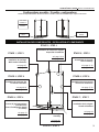
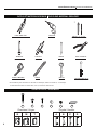
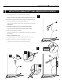
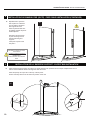
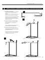
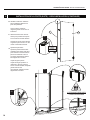
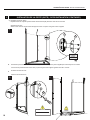
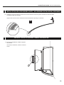
GUIDE D’INSTALLATION - INSTRUCTION MANUAL
P001
Panneau et porte en verre courbé - Curved glass Panel and door
08.14
Veuillez conserver ce manuel et le code de produit pour des références futures,
et au besoin, la commande les pièces de rechange.
Please keep this manual and product code number for future reference and
replacement parts ordering if necessary.
INSTRUCTIONS GÉNÉRALES
• Lire attentivement et complètement le manuel
d’installation avant de procéder.
• Il est recommandé de porter des lunettes de sécurité
en tout temps lors de l’installation.
GENERAL INSTRUCTIONS
• Read this manual carefully and completely before
proceeding.
• It is recommended that you wear safety glasses at
all times during the installation.
INSTALLATION SUR LES TUILES EN CÉRAMIQUE
• Le calfeutrage doit être appliqué sur le côté extérieur
de la douche où le panneau fixe rencontre les tuiles
de la base.
• Si votre porte de douche doit être installée sur une
base en céramique, les tuiles doivent couvrir complètement le dessous du jambage.
INSTALLATION OVER CERAMIC TILES
• Silicone should be used to seal the gap where the
ceramic tiles meet the fixed panel.
• If your shower door is to be installed over ceramic
tiles, the tiles should lay completely under the wall
jamb.
NOTE
• Calfeutrage: aucun scellant n’est nécessaire à
l’intérieur de la douche. Sauf indication contraire.
• Certains modèles sont dotés de joints d’étanchéité
claire.
NOTICE
• Caulking: no sealant is required inside the shower.
Unless otherwise stated.
• Some models are equipped with clear sealing
gaskets.
L’ENTRETIEN DE VOTRE DOUCHE
• Ne jamais utiliser de poudre ou de tampon à récurer,
ni d’instrument tranchant sur les parties en métal ou
en verre. De temps à autre, il suffit de nettoyer la
porte avec une solution d’eau et de détergent doux
pour conserver l’aspect neuf des panneaux de verre
et du cadre en aluminium.
• Nous recommandons de passer une raclette de
douche sur les panneaux de verre après chaque
utilisation.
CARE FOR YOUR SHOWER DOOR
• Never use scouring powder pads or sharp instruments on metal pieces or glass panels. An occasional wiping down with a mild soap diluted in water
is all that is needed to keep the panels and aluminum parts looking new.
• We recommend wiping the glass panels with a
squeegee after each use.
Des changements peuvent être apportés au produit
sans préavis.
2
Product specifications are subject to change without
notice.
GUIDE D’INSTALLATION INSTALLATION MANUAL
Configurations possible
/ Possible configurations
FRM2-448
FRM2-460
FRM2-472
Suivre les étapes d’installation dans l’ordre selon le modèle / Follow the installation steps
require for the model
BASE VENDUE
SÉPARÉMENT.
BASE SOLD
SEPARETLY.
Base
RIGHT
Base
LEFT
INSTALLATION DES COMPOSANTES / INSTALLATION OF COMPONENTS
ÉTAPE 3 / STEP 3
ÉTAPE 1 / STEP 1
Installation de la barre de support
Suport Bar Installation
voir page 10-12
see page 10-12
Installation du jambage
Wall Jambs Installation
Assemblage de la porte
Door Assembly
voir page 13-16
see page 13-16
voir page 6-7
see page 6-7
ÉTAPE 2 / STEP 2
ÉTAPE 5 / STEP 5
ÉTAPE 6 / STEP 6
Installation du panneau fixe
Fix Panel Installation
Installation des accessoires
Accesories Installation
voir page 8-10
see page 8-10
voir page 17-19
see page 17-19
ÉTAPE 7 / STEP 7
ÉTAPE 4 / STEP 4
Inserez le joint magnetique
(Panneau fixe)
Insert The Magnetic Gasket
(Fix Panel)
voir page 13
see page 13
Installation de la poignée
Handle Installation
Calefeutrage
Caulking
voir page 20
see page 20
ÉTAPE 8 / STEP 8
voir page 19
see page 19
3
GUIDE D’INSTALLATION INSTALLATION MANUAL
PS66
OUTILS ET MATERIAUX REQUIS TOOLS AND MATERIAL REQUIRED
*
PINCE SERRE ÉTAU
LONG NOSE LOCKING PLIER
PERÇEUSE
DRILL
TOURNEVIS
SCREWDRIVERS
RUBAN À MESURER
TAPE MEASURE
MÈCHE 1/4˝ & 1/16˝
1/4˝& 1/16˝ DRILL BITS
SCELLANT
SILICONE
CRAYON
PENCIL
NIVEAU
LEVEL
MAILLET
MALLET
PINCE COUPANTE
CUTTING PLIER
TOURNE-ÉCROU 5/16”
5/16” HEX NUT DRIVER
*Pour installer la porte de douche sur des tuiles en céramique, utiliser une mèche 1/4’’ à céramique/
To install the shower door on ceramic tiles, use a 1/4’’ drill bit for ceramic tiles.
QUINCAILLERIE / HARDWARE
16
17
13
Charnières / Hinges
Q
4
M
T
18
15
14
Poignée / Handles
A
B
C
D
GUIDE D’INSTALLATION INSTALLATION MANUAL
LISTE DES PIÈCES / PARTS LISTING
12
6
7
9
CHARNIÈRES
HINGE
POIGNÉE / HANDLE
1
4
2
3
8
9
CHARNIÈRES
HINGE
5
10
11
ITEM
PIÈCES - PARTS
QTY
1
JAMBAGE - WALL JAMB
1
2
PANNEAU DE PORTE / DOOR PANEL
1
3
PANNEAU FIXE / SIDE PANEL
1
4
JOINT D’ETANCHÉITÉ MURAL / WALL SIDE GASKET
1
5
JOINT INFÉRIEUR / BOTTOM DOOR GASKET
1
6
JOINT MAGNÉTIQUE DE PORTE / MAGNETIC DOOR GASKET
1
7
JOINT MAGNÉTIQUE POUR LE PANNEAU FIXE / MAGNETIC SIDE PANEL GASKET
1
8
POIGNÉE / HANDLES
1
9
CHARNIÈRES / HINGE
2
10
SUPPORT DE VERRE / GLASS SUPPORT
2
11
SEUIL DE RETENTION / THRESHOLD
1
12
BARRE DE SUPPORT / SUPORT BAR
1
ITEM
QUINCAILLERIE - HARDWARE
QTY
13
CHEVILLE / WALL PLUG # 1/4” x 1”
3
14
CAPUCHON COUVRE-VIS / SCREW CAP
4
15
L’ ARRIÈRE DU CAPUCHON COUVRE-VIS / BACK SCREW CAP
4
16
VIS PAN AUTO-PERÇANTE / PAN SELF DRILLING SCREW #8-3/8”
3
17
VIS PAN AUTO-PERÇANTE / PAN HEAD SELF DRILLING SCREW # 8 - 1 1/4”
3
18
BLOC A NIVEAU / SETTING BLOCK
2
5
GUIDE D’INSTALLATION INSTALLATION MANUAL
PS66
INSTALLATION DU JAMBAGE / WALL JAMB INSTALLATION
1
1a. Marquer le centre du seuil de la base
à l’aide d’un crayon et d’un ruban à
mesurer.
1a
Use a measuring tape and pencil to
mark the center of the threshold of the
base.
THE INSTALLATION SHOWN IS BASED ON
PLUMB FINISHED WALLS AND A LEVELLED
BASE. IF THESE CONDITIONS ARE NOT MET,
PLEASE ADJUST ACCORDINGLY.
L’INSTALLATION ILLUSTRÉE EST BASÉE SUR
DES MURS FINIS D’APLOMB ET UNE BASE DE
DOUCHE NIVELÉE. SI CES CONDITIONS NE
SONT PAS PRÉSENTÉES, VEUILLEZ AJUSTER
EN CONSÉQUENCE.
INTÉRIEUR DE
LA DOUCHE
INTERIOR
SHOWER SIDE
1b Placer le jambage aux mur en centrant
l’ouverture sur la ligne marquée
précédemment pour que les trous soient
vers l’intérieur de la douche.
Assurer la verticalité du jambage à l’aide
du niveau.
Marquer l’emplacement des trous avec un
crayon en utilisant les trous du jambage
comme référence.
1b
INTÉRIEUR DE
LA DOUCHE
INTERIOR
SHOWER SIDE
Place the wall jamb against the wall so
that the holes are located towards the
interior of the shower.
Center the opening of the wall jamb on the
line marked previously.
Ensure verticality with a level.
Mark the holes position with a pencil using
the holes of the wall jamb for reference.
.
6
1
GUIDE D’INSTALLATION INSTALLATION MANUAL
PS66
1
INSTALLATION DU JAMBAGE (SUITE )/ WALL JAMB INSTALLATION (CONTINUED)
1c Percer des trous avec une mèche à céramique de Ø1/4’’.
1c
Drill the holes in the wall with Ø1/4’’ drill bit intented for ceramic tiling .
1d Introduire une goutte de silicone dans chaque trou percé dans le mur
avant d’y insérer une cheville (x3) dans chaque trou.
Insert one drop of silicone in each hole in the wall before inserting the
wall plug (x3) .
1e Appliquez de la silicone au mur ou le jambage sera installer.
Apply silicone to the wall where the wall jamb will be installed.
1f Assurer la verticalité avec le niveau.
Visser le jambage au mur à l’emplacement de chevilles en utilisant les
vis 1 1/4’’ (3) .
Ensure verticality with the level.
Screw the wall jamb on to the wall using the screws 1 1/4’’ (x3) .
1g Appliquez du silicone à l’intérieur du jambage tel qu’illustré .
Apply silicone on the inside of the wall jamb as illustrated.
INTÉRIEUR DE
LA DOUCHE
INTERIOR
SHOWER SIDE
1f
1e
17
1d
13
1g
1
7
GUIDE D’INSTALLATION INSTALLATION MANUAL
PS66
INSTALLATION DU PANNEAU FIXE / FIXED PANEL INSTALLATION
2
2a Placer les supports de verre (x2) sur l’arête inférieure du panneau fixe .
Place glass supports (x2) on the bottom of the fixed panel.
ASSUREZ-VOUS POUR QUE LES
SUPPORTS DE VERRE SOIENT PLACÉS
TELL QU’ILLUSTRÉ.
2b Glisser temporairement le panneau fixe dans le jambage.
Slide the fix panel temporarily into the wall jamb.
MAKE SURE TO PLACE THE GLASS
SUPPORTS AS ILLUSTRATED.
2c Marquer les emplacements des supports de verre sur la base.
3
Mark the glass supports locations on the base.
2a
1”
VUE DU HAUT /
TOP VIEW
VUE DU HAUT /
TOP VIEW
1”
10
10
2b
8
2c
GUIDE D’INSTALLATION INSTALLATION MANUAL
2
INSTALLATION DU PANNEAU FIXE (SUITE) / FIXED PANEL INSTALLATION (CONTINUED)
2d Enlever le panneau fixe et les supports de verre.
2d
Remove the fix panel and the glass supports.
2e Repositionner les supports de verre sur la base en utilisant les lignes de
marquage.
Percer des trous à travers la base avec une meche de 1/16” en utilisant
les supports de verre comme guide.
Reposition the glass supports on the base using the line marked
previously. Use a 1/16” drill bit to drill holes into the base through the
glass supports.
2f Enlever les supports de verre at introduire une goutte de silicone dans
chaque trou percé dans la base .
Remove the clips and insert one drop of silicone in each hole in the base.
2g Visser les supports à la base en utilisant les vis fournies.
Screw the glass supports by using the screws supplied.
VUE DU HAUT /
TOP VIEW
2e
10
2f
2g
9
GUIDE D’INSTALLATION INSTALLATION MANUAL
2
2h
INSTALLATION DU PANNEAU FIXE (SUITE) / FIXED PANEL INSTALLATION (CONTINUED)
Repositionner le panneau
fixe en place en s’assurant
qu’il est inséré a l’intérieur
des supports de verre.
Serrer le panneau fixe avec
le jambage à l’aide de pinces
autobloquantes.*
2h
Reposition the fixed panel
in place ensuring that it is
placed inside the glass
supports.
Clamp the fix panel to the
wall jamb.*
RECOUVREZ LES DENTS DE LA PINCE
AFIN DE NE PAS
GRAFIGNER LES PIÈCES EN ALUMINIUM.
COVER THE PLIER’S TEETH
BEFOREHAND TO
AVOID SCRATCHING THE ALUMINUM
PARTS.
3
3a
INSTALLATION DE LA BARRE DE SUPPORT / SUPORT BAR INSTALLATION
Placer temporairement la barre de support sur l’arête supérieure du panneau fixe et marquer l’emplacement au mur.
Assurer l’horizontalité de la barre de support à l’aide du niveau.
Place temporarily the suport bar on the top of the fix panel.
Ensure verticality with a level and mark the position on the wall.
12
3a
1”
10
GUIDE D’INSTALLATION INSTALLATION MANUAL
INSTALLATION DE LA BARRE DE SUPPORT (SUITE) / SUPORT BAR INSTALLATION
3
3b Enlever la barre de support.
A l’aide de la clé hexagonale fournie, devisez
la composante murale (A) de la barre de
support.
Repositionner la composante murale (A) sur
le mur en utilisant les lignes de marquage.
Remove the suport bar and take apart the wall
end component (A) with the provided Key.
Replace the wall end component on the wall
using the marked lines.
3b
A Composante murale
B
3c
Wall end component
A
3c Utilisez la composante murale (A) comme
référence pour percer un trou dans le mur
avec une meche 1/4” (à ceramique si
necessaire).
Use a 1/4” drill bit to drill a hole into the wall
through the wall end component (A).
3d Appliquer une goutte de silicone dans le
trou percé dans le mur avant d’y insérer une
cheville.Sécurisez la composante murale (A)
au mur à l’aide de la vis.
Apply a bead of silicone in the hole and insert
a wall plug. Use a screw to secure the wall
end component (A) to the wall .
3d
11
GUIDE D’INSTALLATION INSTALLATION MANUAL
3
INSTALLATION DE LA BARRE DE SUPPORT (SUITE)/ SUPORT BAR INSTALLATION
3e Repositionner la barre de support tel qu’illustré .
Pour faciliter l’installation subséquente sur le panneau avant
insérez la barre dans le composant mural (A) sur une plane
horizontale tel qu’illustré.
S’assurer d’insérer la gaine claire telle qu’illustrée avant
l’installation sur le panneau fixe.
3e
Reposition the suport bar as illustrated.
To ease subsequent installation on the fix panel insert bar in
the wall end component (A) on a horizontal plane as shown.
Make sure you insert the clear gasket as shown before
installing it on the fix pannel .
3f. Nivelez le bar de support.
Sécurisez les vis de l’attache à verre ainsi que du support
mural afin de compléter l’installation.
Level support bar and tighten the set screws.Secure the glass
fastener and wall bracket screws to complete the installation
process.
A
12
B
3f
Gaine claire
Clear gasket
B
12
12
3
VUE DU HAUT /
TOP VIEW
GUIDE D’INSTALLATION INSTALLATION MANUAL
4
INSÉREZ LE JOINT MAGNÉTIQUE (PANNEAU FIXE) / INSERT THE MAGNETIC GASKET (FIX PANEL)
4a Installer à l’aide d’un maillet
le joint magnétique latéral
sur le panneau fixe.
INTÉRIEUR DE
LA DOUCHE
INTERIOR
SHOWER SIDE
Use a mallet to install the
magnetic gasket on the fix
panel.
Make sure it touches the
base.
4a
6
INSTALLATION DE LA PORTE / DOOR INSTALLATION
5
5a Fixez les charnières au porte tel qu’illustré. Utilisez la clé hexagonale fournie.
Fasten the hinges to the door as illustrated. Use the provided hex. Key.
B
5a
A
INTÉRIEUR DE
LA DOUCHE
INTERIOR
SHOWER SIDE
B
INTÉRIEUR DE
LA DOUCHE
INTERIOR
SHOWER SIDE
9
A
INTÉRIEUR DE
LA DOUCHE
INTERIOR
SHOWER SIDE
B
A - Partie en avant du charnièr/
Front side of the Hinge
2
B
B - Partie arrière du charnièr /
Back side of the Hinge
13
GUIDE D’INSTALLATION INSTALLATION MANUAL
INSTALLATION DE LA PORTE (SUITE) / DOOR INSTALLATION (CONTINUED)
5
5b Installer à l’aide d’un maillet le
joint magnétique latéral sur la
porte tel qu’illustrée.
Use a mallet to install the
magnetic gasket on the door as
illustrated.
5c Utilisez les deux blocs de bois
fournis pour positionner la porte
sur le centre du seuil de la base.
6
2
5b
Use the two wood blocks that are
supplied to place the door on the
center of the base threshold .
INTÉRIEUR DE
LA DOUCHE
INTERIOR
SHOWER SIDE
5d Ajustez les panneaux.
Ajustez le positionnement des
charnières par rapport à la porte
pour assurer un contact entre le
joint de la charnière et le mur.
Les joints magnétiques doivent
être alignés et en contact.
Adjust the glass panels.
Adjust the hinges positions in
reference to the door panel to
ensure contact between backplate
gasket and the wall.
The magnetic gaskets must be
aligned and in contact.
5c
5d
2 PERSONNES REQUISES
2 PEOPLE REQUIRED
5c
18
18
14
GUIDE D’INSTALLATION INSTALLATION MANUAL
INSTALLATION DE PORTE (SUITE) / DOOR INSTALLATION (CONTINUED)
5
5e Marquez les emplacements des charnières et de
perçage au mur.
5e
Mark the hinges and drilling locations on the wall
5f Enlever temporairement l’assemblage de la
porte et percer des trous en utilisant les lignes
de marquage.
Remove the door temporarily and drill holes in
each location .
INTÉRIEUR DE
LA DOUCHE
INTERIOR
SHOWER SIDE
5g Introduire une goutte de silicone dans chaque
trou percé dans le mur avant d’y insérer une
cheville (x4) dans chaque trou.
Insert one drop of silicone in each hole before
inserting the wall plug (x4) .
5h
Enlevez les charnières.
A l’aide de la clé hexagonale fournie,dévisez la
partie en avant (A) de la charniere et repositionner-le au mur .Fixez-le avec les vis fournies.
Remove the hinges
Take apart the hinge’s front part (A) with the
provided hex Key.
Place the hinge’s front part (A)on the wall using
the marked lines and screw it in place using the
screws supplied.
5f
5g
5h
B
A
A
5h
15
GUIDE D’INSTALLATION INSTALLATION MANUAL
5
INSTALLATION DE LA PORTE (SUITE) / DOOR INSTALLATION (CONTINUED)
5j Remetez la porte en place .
Repositionnez sur la porte la partie arrière des charnières( B) et fixez-le avec les vis fournies.
Reposition the door .
Place on the door the hinge’s back side (B) and screw it in place using the screws supplied.
5j
A
B
INTÉRIEUR DE
LA DOUCHE
INTERIOR
SHOWER SIDE
5k
Sécurisez le panneau fixe à l’aide de vis 3/8” (x3) en s’assurent que les joints magnétiques soient toujours en contact.
Secure the fix panel with the screws 3/8” (x3) ensuring that the magnetic gaskets are still in contact .
5l
Enlevez les blocs de bois.
Remove the wood blocks.
5l
5k
15
16
14
ENLEVEZ LES BLOCS DE BOIS.
REMOVE THE WOOD BLOCKS.
16
GUIDE D’INSTALLATION INSTALLATION MANUAL
6
INSTALLATION DES ACCESSOIRES / ACCESSORIES INSTALLATION
6a
Le joint vertical doit être installé à l’intérieur de la douche.
The gasket must be installed inside the shower.
6b
Insérez le joint inférieur tel qu’illustré .
Insert the bottom gasket as illustrated.
INTERIOR
SHOWER SIDE
9
INTÉRIEUR DE
LA DOUCHE
4
TOP VIEW
VUE DU HAUT
6b
INTERIOR
SHOWER SIDE
INTÉRIEUR DE
LA DOUCHE
INTERIOR
SHOWER SIDE
5
INTÉRIEUR DE
LA DOUCHE
INTERIOR
SHOWER SIDE
INTÉRIEUR DE
LA DOUCHE
½"
INTERIOR
SHOWER SIDE
INTÉRIEUR DE
LA DOUCHE
17
GUIDE D’INSTALLATION INSTALLATION MANUAL
65
INSTALLATION DES ACCESSOIRES (SUITE) / ACCESSORIES INSTALLATION (CONTINUED)
6c Tracer l’emplacement de la porte sur la base (quand fermée).
Trace the location of the door on the base (when closed).
6c
6d. Pour avoir un assemblage correct , placez le seuil de rétention contre le mur et le support de verre en utilisant la ligne de
marquage avant d’ajouter le silicone .
To have a correct fit place the threshold against the wall and the glass support before adding the silicone.
6d
11
18
GUIDE D’INSTALLATION INSTALLATION MANUAL
65
INSTALLATION DES ACCESSOIRES (SUITE) / ACCESSORIES INSTALLATION (CONTINUED)
6e Appliquez une ligne de silicone au dessous du seuil de rétention avant de le placer au dessus du seuil de la base
en utilisant la ligne de marquage.
Apply a bead of silicone to the underside of the threshold before replacing it on the base.
6e
INSTALATTION DE LA POIGNÉE / HANDLE INSTALLATION
7a Voir la fiche d’installation, installer la poignée
tel qu’illustré.
See sheet for installation, install the handle as
shown.
*
POIGNÉE / HANDLE
7
8
19
GUIDE D’INSTALLATION INSTALLATION MANUAL
PS66
8
CALFEUTRAGE / SEALING
8a
Calfeutrer avec du silicone l’extérieur de l’unité entre le mur et le jambage (Fig.1), en bas du panneau fixe (Fig.2) et à l’exterieur
du seuil en aluminium(Fig.3).
Silicone the outside of the shower unit between the wall and the wall jamb (Fig.1), below the fix panel (Fig.2) and on the exterior
side of the aluminum threshold (Fig.3).
8b
Attendre 24 heures avant de faire fonctionner la douche pour laisser le silicone séché.
Wait 24 hours before using the shower to allow the silicon to dry.
INTÉRIEUR DE
LA DOUCHE
INTERIOR
SHOWER SIDE
8a
ONLY SEAL THE OUTSIDE OF THE
UNIT. DO NOT APPLY SILICONE TO
THE INSIDE OF THE SHOWER.
SCELLER SEULEMENT
L’EXTÉRIEURE DE LA DOUCHE. NE
PAS APPLIQUER LA SILICONE À
L’INTÉRIEUR DE LA DOUCHE.
(1)
(3)
(2)
8b
20
(3)
HEURES
HOURS