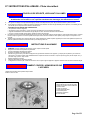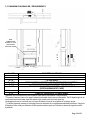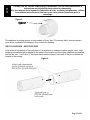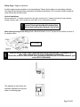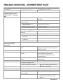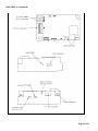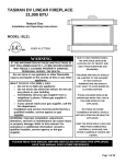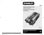
1
BL-936 BUILDER’S LINEAR 15,500 BTU Natural Gas Installation and Operating Instructions MODEL: BL-936 CLIENT # LC773211 WARNING IF THE INFORMATION IN THESE INSTRUCTIONS IS NOT FOLLOWED EXACTLY, A FIRE OR EXPLOSION MAY RESULT CAUSING PROPERTY DAMAGE, PERSONAL INJURY, OR DEATH. Do not store or use gasoline or other flammable vapors and liquids in the vicinity of this or any other appliance. WHAT TO DO IF YOU SMELL GAS: Do not try to light any appliance Do not touch any electrical switch; do not use any phone in your building Immediately call your gas supplier from a neighbour’s phone. Follow gas supplier’s instructions If you cannot reach your gas supplier, call the fire department. Installation and service must be performed by a qualified installer, service agency or gas supplier. WARNING: Improper installation, adjustment, alteration, services or maintenance can cause injury or property damage. Refer to this manual. For assistance or additional information consult a qualified installer, service agency or the gas supplier. INSTALLER: Leave this manual with the appliance. CONSUMER: Retain this manual for future reference. PLEASE READ THIS MANUAL BEFORE INSTALLING OR USING THIS APPLIANCE. SAVE THIS MANUAL FOR FUTURE REFERENCE. A BARRIER DESIGNED TO REDUCE THE RISK OF BURNS FROM THE HOT VIEWING GLASS IS PROVIDED WITH THIS APPLIANCE AND SHALL BE INSTALLED. Page 1 of 51 BL-936 LA LINEAR BUILDER 15,500 BTU GAZ NATUREL Manuel D’installation et Guide de l’utilisateur MODEL: BL-936 CLIENT # LC773211 AVERTISSEMENT ASSUREZ-VOUS DE BIEN SUIVRE LES INSTRUCTIONS DONNÉES DANS CETTE NOTICE POUR RÉDUIRE AU MINIMUM LE RISQUE D'INCENDIE OU D'EXPLOSION OU POUR ÉVITER TOUT DOMMAGE MATÉRIEL, TOUTE BLESSURE OU LA MORT. Ne pas entreposer ni utiliser d'essence ni d'autres vapeurs ou liquids inflammables dans le voisinage de cet appareil ou de tout autre appareil. QUE FAIRE SI VOUS SENTEZ UNE ODEUR DE GAZ: Ne pas tenter d'allumer d'appareil. Ne touchez à aucun interrupteur. Ne pas vous servir des telephones se trouvant dans le bâtiment où vous vous trouvez. Appelez immédiatement votre fournisseur de gaz depuis un voisin. Suivez les instructions du fournisseur. Si vous ne pouvez rejoindre le fournisseur de gaz, appelez le service des incendies. L'installation et l'entretien doivent être assurés par un installateur ou un service d'entretien qualifié ou par le fournisseur de gaz. AVERTISSEMENT: Une mauvaise installation, de réglage, la modification, de services ou de maintenance peut causer des dommages corporels ou matériels. Reportez-vous à ce manuel. Pour toute assistance ou information supplémentaire, consulter un installateur qualifié, un service ou le fournisseur de gaz. INSTALLATEUR : Laissez cette notice avec l’appareil. CONSOMMATEUR : Conservez cette notice pour consultation ultérieure. S'IL VOUS PLAIT LIRE CE MANUEL AVANT D'INSTALLER OU UTILISER CET APPAREIL. CONSERVEZ CE MANUEL POUR REFERENCE FUTURE. AVERTISSEMENT Une surface vitrée chaude peut causer des brûlures. Laisser refroidir la surface vitrée avant d’y toucher Ne permettez jamais à un enfant de toucher la surface vitrée. BARRIÈRE conçu pour réduire le risque de brûlures et à la consultation verre chaud EST FOURNI AVEC CET APPAREIL ET DOIT SE. Page 2 of 51 Table of Contents IMPORTANT SAFETY INFORMATION …………………………………………………………….. 4 – 5 1.0 INTRODUCTION ..................................................................................................................... 1.1 Specifications, Appliance Dimensions & Installation Codes ................................. 6 - 7 1.2 Features, Remote Control Functions .................................................................. 8 - 10 1.3 Intended Use ............................................................................................................ 11 1.4 General Safety.................................................................................................. 11 - 12 2.0 OPERATION ........................................................................................................................... 2.1 Lighting Instructions ......................................................................................... 13 – 16 2.2 Heat Output adjustment……………………………………………………………………17 3.0 INSTALLATION ...................................................................................................................... 3.1 Installation & Safety Notes ...................................................................................... 17 3.2 Unpacking ................................................................................................................ 18 3.3 Installation ............................................................................................................... 18 3.3.1 Minimum Clearances & Non Combustible Material Requirements .......................... 19 3.3.2 Gas Line Installation ................................................................................................ 20 3.3.3 Thermostat,Wall Switch or Digital On/Off Remote………………………………..21 - 22 3.3.4 Direct Vent Information .................................................................................... 22 - 28 3.3.5 Glass Media Installation ........................................................................................... 29 3.3.6 Door Installation and Safety Scren ................................................................... 30 – 31 3.3.7 Initial Firing .............................................................................................................. 31 3.3.8 Manifold Pressure..................................................................................................... 32 3.3.9 Primary Air Adjustment .................................................................................... 32 - 33 3.3.10 Altitude Adjustment .................................................................................................. 33 3.3.11 Gas Valve Access .................................................................................................... 34 4.0 MAINTENANCE ..................................................................................................................... 4.1 Maintenance Safety ................................................................................................. 35 4.2 Recommended Service ........................................................................................... 35 4.3 Glass Cleaning ........................................................................................................ 36 4.4 Burner & Pilot Cleaning ........................................................................................... 36 4.5 Valve & Pilot Replacement ............................................................................. 36 - 37 5.0 TROUBLE SHOOTING ……………………………………………………………….……. 38 – 41 6.0 REPLACEMENT PARTS ………………………………………………………………………...42 7.0 WARRANTY .………………………………………………………………………………....43 - 45 8.0 LABEL INFORMATION .………………………………………………………………….…46 - 47 APPENDIX A (INTERMITTENT PILOT & VALVE KIT)……………………....………………….48 - 51 Page 3 of 51 WARNING Read this owner’s manual carefully and completely before trying to assemble, operate or service this fireplace. Follow instructions for proper installation Failure to install this appliance per the manufacturer’s instructions or failure to use only parts specifically approved with this appliance may result in property damage or personal injury. Any change to this fireplace or its controls can be dangerous. Improper installation or use of this fireplace can cause serious injury or death from fire, burns, explosions, electrical shock and carbon monoxide poisoning. AVERTISSEMENT • Lisez ce manuel attentivement et complètement avant d'essayer de monter, utiliser ou entretenir ce foyer. Suire les instructions pour assurer une bonne installation. • Risque de dommages ou de blessures si l’appareil n’est pas installé selon les instructions du fabricant ou si des pièces autres que celles spécifiquement approuvées avec cet appareil sont utilisées. Tout changement à ce foyer ou à ses contrôles peuvent être dangereux. • Une mauvaise installation ou l'utilisation de cette cheminée peut causer des blessures graves ou la mort par le feu, les brûlures, explosions, de chocs électriques et intoxication au monoxyde de carbone. DUE TO HIGH TEMPERATURES, THE APPLIANCE SHOULD BE LOCATED OUT OF TRAFFIC AND AWAY FROM FURNITURE AND DRAPERIES. CHILDREN AND ADULTS SHOULD BE ALERTED TO THE HAZARDS OF HIGH SURFACE TEMPERATURE AND SHOULD STAY AWAY TO AVOID BURNS OR CLOTHING IGNITION. YOUNG CHILDREN SHOULD BE SUPERVISED WHEN THEY ARE IN THE SAME ROOM AS THE APPLIANCE. CLOTHING OR OTHER FLAMMABLE MATERIAL SHOULD NOT BE PLACED ON OR NEAR THE APPLIANCE. KEEP THE ROOM AREA CLEAR AND FREE FROM COMBUSTIBLE MATERIALS, GASOLINE, AND OTHER FLAMMABLE VAPORS AND LIQUIDS. IF THE BARRIER BECOMES DAMAGED, THE BARRIER SHALL BE REPLACED WITH THE MANUFACTURER’S BARRIER FOR THIS APPLIANCE EN RAISON DE TEMPERATURES ELEVEES, L'APPAREIL DOIT ETRE PLACE HORS DE LA CIRCULATION ET LOIN DES MEUBLES ET TENTURES. ENFANTS ET ADULTES DOIVENT ETRE AVERTIS DES DANGERS DE LA TEMPERATURE DE SURFACE ELEVEE ET DEVRAIT RESTER A L'ECART POUR EVITER LES BRULURES OU L'INFLAMMATION DES VETEMENTS. LES JEUNES ENFANTS DOIVENT ETRE SOIGNEUSEMENT SURVEILLES QUAND ILS SONT DANS LA MEME PIECE QUE L'APPAREIL. CLOTHING OR OTHER MATERIAUX COMBUSTIBLES NE DOIVENT PAS ETRE PLACES SUR OU PRES DE L'APPAREIL. GARDER LA ZONE SALLE CLAIRE ET LIBRE DE MATERIAUX COMBUSTIBLES, D'ESSENCE, ET AUTRES VAPEURS ET LIQUIDES SI LA BARRIÈRE EST ENDOMMAGÈE, LA BARRIÈRE DOIT ÈTRE REMPLACÈE PAR LA BARRIÈRE DE LA FABRICANT DE CET APPAREIL Page 4 of 51 WARNING Do not use this appliance if any part has been under water. Immediately call a qualified service technician to inspect the appliance and to replace any part of the control system and any gas control which has been under water. Toddlers, young children and others may be susceptible to accidental contact burns. A physical barrier is recommended if there are at risk individuals in the house. To restrict access to a fireplace or stove install an adjustable safety gate to keep toddlers, young children and at risk individuals out of the room and away from hot surfaces. Any safety screen or guard removed for servicing an appliance must be replaced prior to operating the appliance. Installation and repair should be done by a qualified service person. The appliance should be inspected before use and at least annually by a professional service person. More frequent cleaning may be required due to excessive lint from carpeting, bedding material, et cetera. It is imperative that control compartments, burners and circulating air passageways of the appliance be kept clean. This fireplace is a vented product. This fireplace must be properly installed by a qualified service person. The glass door must be properly seated and sealed. If this unit is not properly installed by a qualified service person with the glass door properly seated and sealed gas leakage can occur. Caution: Label all wires prior to disconnection when servicing controls. Wiring errors can cause improper and dangerous operation. Verify proper operation after servicing If appliance is installed directly on carpeting, vinyl tile or other combustible material other than wood flooring, the appliance shall be installed on a metal or wood panel extending the full width and depth of the fireplace. AVERTISSEMENT Ne pas utiliser cet appareil s’il a été plongé, meme partiellement, dans l’eau. Appeler un technician qualifié pour inspecter l’appareil et remplacer toute partie du système de commande et toute commande qui a été plongée dans l’eau. Les tout-petits, les jeunes enfants et d'autres peuvent être sensibles aux brûlures par contact accidentel. Une barrière physique est recommandé s'il ya des personnes à risque dans la maison. Pour restreindre l'accès à une cheminée ou un poêle installer une barrière de sécurité réglable pour garder les tout-petits, les jeunes enfants et les personnes à risque de la salle et à l'écart des surfaces chaudes. Tout écran ou grille de protection pour l'entretien d'un appareil doit être remplacé avant de faire fonctionner l'appareil. Installation et réparation doit être effectuée par un technicien qualifié. L'appareil doit être inspecté avant son utilisation et au moins annuellement par un technicien qualifié. Un nettoyage plus fréquent peut être nécessaire en raison de peluches provenant des tapis, literie, etc. Il est impératif que les compartiments de contrôle, les brûleurs et les conduits d'air de l'appareil soient gardés propres. Ce foyer est un produit ventilé. Ce foyer doit être correctement installé par un technicien qualifié. La porte en verre doivent être placés correctement et scellé. Si cet appareil n'est pas correctement installé par un technicien qualifié avec la porte en verre bien en place et des fuites de gaz scellés peuvent se produire. Attention : Au moment de l’entretien des commandes, étiquetez tous les fils avant de les débrancher. Des erreurs de câblage peuvent entraîner un fonctionnement inadéquate et dangereux. S’assurer que l’appareil fonctionne adéquatement une fois l’entretien terminé Si l'appareil est installé directement sur un tapis, carreaux de vinyle ou autre matériau combustible autre qu'un plancher de bois, l'appareil doit être installé sur un panneau de métal ou de bois se prolongeant sur toute la largeur et la profondeur de la cheminée. Page 5 of 51 1.0 INTRODUCTION 1.1 SPECIFICATIONS TABLE 1 ITEM NATURAL GAS (NG) INPUT: Hi 15,500 Btu/hr (4.54 kW) INPUT: Lo 11,000 Btu/hr (3.22 kW) MANIFOLD PRESSURE: Hi COLLECTEUR DE PRESSION: FORT 3.5” w.c. (0.87 kPa) MANIFOLD PRESSURE: Lo COLLECTEUR DE PRESSION: 1.7” w.c. (0.42 kPa) FAIBLE GAS INLET SUPPLY PRESSURE: Minimum: 5.0” w.c. (1.2 kPa) ENTREE DE PRESSION Maximum: 13.5” w.c. (3.4 kPa) ORIFICE SIZE: @ 0-4500’ FORMAT D'ORIFICE: # 49 DMS AIR SHUTTER OPEN 1/8”min VOLET DE L’AIR (3.175mm) CONTROL VALVE TYPE: Skytech AF-40004 TYPE DE SOUPAPE Apex Control B081 VENTING 2-ply aluminum vent ÉVACUATION THIS APPLIANCE IS ONLY FOR USE WITH THE TYPE OF GAS INDICATED ON THE RATING PLATE. CET APPAREIL DOIT ÊTRE UTILISÉ UNIQUEMENT AVEC LE TYPE DE GAZ INDIQUÉ SUR LA PLAQUE SIGNALÉTIQUE. Page 6 of 51 APPLIANCE DIMENSIONS 34.74” 8.75” 32.38” 27.92” 22.64” 10.28” 17.37” 1.00” 0.50” 34.20” 39.19” INSTALLATION CODES This appliance is a Direct Vent appliance which draws all combustion air from outside the building through an intake vent pipe. Installation must conform to local codes. In the absence of local codes, installation must conform to the National Fuel Gas Code ANSI Z223.1/NFPA 54, or the current Natural Gas and Propane Installation Code CSA B149.1. The unit, when installed, must be electrically grounded in accordance with local codes or, in the absence of local codes, with the National Electric Code ANSI/NFPA No.70 or with the current Canadian Electrical Code CSA C22.1. In the state of Massachusetts, this product can only be installed by a licensed plumber or a licensed gas fitter. Failure to comply will void the warranty. This appliance has been certified for use with natural gas. This appliance is not for use with solid fuels. CODES D'INSTALLATION Cet appareil est un appareil à évent direct, qui attire tous l'air de combustion provenant de l'extérieur du bâtiment par une entrée d'évent. L'installation doit se conformer aux codes locaux. En l'absence de codes locaux, l'installation doit être conforme au National Fuel Gas Code ANSI Z223.1/NFPA 54, ou le gaz naturel actuel et le Code d'installation du propane CSA B149.1. L'unité, une fois installé, doit être électriquement à la terre conformément aux codes locaux ou, en l'absence de codes locaux, avec le National Electric Code ANSI / NFPA No.70 ou avec l'actuel Code canadien de l'électricité CSA C22.1 Cet appareil a été certifié pour une utilisation avec du gaz naturel. Cet appareil n'est pas pour une utilisation avec des combustibles solides. Page 7 of 51 1.2 FEATURES Ignition system: Standing pilot ignition system with thermopile and thermocouple flame detection and piezo igniter. Gas control: * Optional* Gas control valve type: Automatic millivolt powered combination gas control valve with variable flame control for convenience and on/off switch. Optional digital remote on/off wall switch and/or optional wall thermostat (note: thermostats are not allowed in the United States). The gas valve does not require electricity from an external source. Electronic Valve: * Optional * Automatic DC valve with AC power adapter. Hand held remote control. Supreme Remote Control Functional Operation Matrix Initial Setup Installation of (2) AAA-size batteries will activate the setup mode. Setup mode can also be activated by pressing the FLAME REAR and PROG/TIME buttons simultaneously for 5 seconds. The control will exit setup mode if no button is pressed for 20 seconds. Appropriate icon on LCD will flash when ready for setup. Press the UP or Down button in setup mode to change the temperature scale. Press SET button to skip or advance to Fuel Type setup. Press the UP or DOWN button to switch control from Natural to LP, or LP to Natural Gas. Press SET button to skip or advance to Clock setup. Press the UP or Down Button to set the hour. Press SET to advance to minutes. Press the UP or Down button to set minutes. Press SET to advance to AM or PM. Press the UP or Down button to set AM or PM. Press the SET button to advance to the day of week. Use UP or Down button to select the day of the week. The control will exit setup mode in 20 seconds. MODE Button The MODE button cycles the unit through the basic operational modes. When off, press and release the MODE button to turn the unit on in Manual mode. Press and release the MODE button again, and the unit will operate in the Thermostat mode. Press and release the MODE button again, and the unit will turn off. Program Mode The Program function is controlled by the PROG/TIME button. The control may be programmed for up to two settings for weekdays and two settings for weekends. The control is preset to factory settings. When the Program Mode is activated, the unit will automatically be operating in the Thermostat Mode. The unit will turn on or off based upon room and set temperature. To activate the Program mode, press and release the PROG/TIME button. To change the settings for the Program mode, press and hold the PROG/TIME button for 5 seconds. The program feature will flash at the top of the screen. Press the UP or DOWN button to change the setting of the weekday (MTWTF) P1 ON. Press and release the SET button. Page 8 of 51 Press the UP or DOWN button to change the setting of P1 OFF. Press and release the SET button. Press the UP or DOWN button to change the setting of P2 ON. Press and release the SET button. Press the UP or DOWN button to change the setting of P2 OFF. Press and release the SET button. Press the UP or DOWN button to change the setting of the weekend (SS) P1 ON. Press and release the SET button. Press the UP or DOWN button to change the setting of P1 OFF. Press and release the SET button. Press the UP or DOWN button to change the setting of P2 ON. Press and release the SET button. Press the UP or DOWN button to change the setting of P2 OFF. Press and release the SET button. The Program Mode has been re-programmed. Countdown Timer The Countdown Timer Mode allows the control to operate the unit for up to 3 hours, in 10-minute increments. It can be operated in either the Manual or Thermostat Modes. To enter Timer Mode, press and release the TIMER button. The Timer icon will flash. Press the UP or DOWN button to set the running time, in 10-minute increments. Press and release the SET button. The timer will run for the set time duration. Pressing the TIMER button while in Timer Mode will terminate the Timer operation. The Timer operation will also terminate if the MODE button is cycled to off. Thermostat Mode The unit is placed in Thermostat Mode using the MODE button. Placing the unit in Thermostat Mode will activate the numbers in the smaller window on the LCD screen. Press the UP or DOWN button to change the thermostat set temperature. When the desired set temperature appears, press and release the SET button to set. If the SET button is not pressed, the set temperature will automatically be set after 5 seconds. The Thermostat Mode can be de-activated by pressing the MODE button. Thermostatic Flame Modulation This control can perform Main Flame Modulation using the Thermostat. The control will shut the unit off when the room temperature reaches 2 above set temperature. The Thermostat will automatically modulate the main flame: Manual Flame Modulation – Main Flame To change the Flame Level manually, press the FLAME MAIN button. The current level will show in the MAIN box on the LCD screen. Press the UP or DOWN button to change the Flame Level. When the unit is turned on, whether in Manual, Thermostatic, or Program Mode, the Main Flame will automatically ignite at the High (7) setting. After 5 seconds, the flame will default to the previous setting. Fan Control (Not applicable on this model) The unit must be ON to operate the Fan. The Fan will turn on after 5 minutes of operation. Once the Fan comes on, it can be controlled using the FAN button. Press the FAN button, and the fan icon and speed will appear on the LCD screen. Press the UP or DOWN button to control the fan speed (0-6). Press the DOWN button until 0 Level is reached to turn the Fan off. The fan will run for 12 minutes after the unit is shut off in any mode. The fan may not be controlled during this period. Page 9 of 51 Continuous Pilot The unit can be changed from Intermittent Pilot Ignition (IPI), to Continuous, or standing, pilot. To place the unit in continuous pilot mode, press and release the PROG/TIME and the FLAME MAIN buttons simultaneously. Continuous Pilot will appear on the LCD screen. Repeat the simultaneous PROG/TIME and FLAME MAIN push to place the unit back in IPI mode. This feature can also be activated by the Continuous Pilot (On/Off) switch on the Main Module. Child Lock-Out The Child Lock-out feature can be activated by pressing the PROG/Time and UP buttons simultaneously. CP will appear on the LCD screen, and no signals can be sent from the transmitter. To take the control out of Child Lock-out mode, repeat the above step. CP will disapper from the screen. Learn Function To program the system to a transmitter, press the LEARN button on the Main Module. A single audible beep will be heard. Press the MODE button on the transmitter to learn the transmitter to the system. A series of beeps will be heard. Up to two additional (NON-THERMOSTATIC) transmitters can be used simultaneously. To learn additional transmitters, press and release the learn button again, and press the on button on the additional transmitters. To clear all transmitters and start over, press and hold the LEARN button for 10 seconds. A series of three beeps will be heard, and the system is clear. Low Battery Indicator A low battery icon will appear on LCD screen when transmitter batteries reach low voltage level. Thermal Safety When the internal components of the Main Module reach 170F, the unit will automatically shut off, and send a repetitive audible signal. The unit can be turned back on when the module cools below 160 Communication Safety When in the Thermostat or Program Mode, the transmitter will send a silent signal to the module every 15 minutes. If a signal is not received within 2 hours due to dead batteries, lost transmitter, or transmitter out of range, the unit will automatically shut down, and the module will send a repetitive audible signal. 1.3 INTENDED USE / USAGE PROPOSÉ This appliance is intended to be used as a zero clearance fireplace. This unit is certified for installation in a bedroom or a bed sitting room or a bathroom where the maximum input is within 50 cubic feet per 1000 Btu/hr, (i.e. 900 cubic feet for E unit & 1600 cubic feet for H unit). In Canada all bedroom installations require the use of wall thermostats (note: thermostats are not allowed in the United States). Cet appareil est destiné à être utilisé comme un foyer à dégagement zéro. Cet appareil est certifié pour une installation dans une chambre ou une chambre à coucher ou une salle de bain assis où l'entrée maximale est de moins de 50 pieds cubes par 1000 Btu / h (i.e. 900 cubic feet for E unit & 1600 cubic feet for H unit). In Canada all bedroom installations require the use of wall thermostats (note: thermostats are not allowed in the United States). Page 10 of 51 1.4 GENERAL SAFETY / SÉCURITÉ GÉNÉRALE Maintain adequate clearances around air openings into the combustion chamber. Respecter les distances minimales convenables autour des bouches d'air dans la chambre de combustion. Maintain adequate accessibility clearances for servicing and proper operation. Respecter les distances minimales d'accessibilité suffisante pour l'entretien et bon. This appliance shall not be connected to chimney flue serving a separate solid-fuel burning appliance. Cet appareil ne doit pas être raccordé à une cheminée desservant un autre appareil brûlant des combustibles solides. The appliance area must be kept clear and free from combustible materials, gasoline and other flammable liquids and vapors. La zone appareil doit rester clair et exempt de matériaux combustibles, essence et autres vapeurs et liquides inflammables. The flow of combustion and ventilation air shall not be obstructed. Le débit de combustion et de ventilation ne doit pas être obstrué. The combustion air supply shall be in the same pressure zone as the drafthood relief opening on an appliance equipped with a drafthood or as the vent outlet on an appliance not equipped with a drafthood. L'alimentation en air de combustion doit être dans la zone même pression que l'ouverture de secours hotte à air sur un appareil équipé d'une hotte à air ou que l'évent de sortie sur un appareil n'est pas équipé d'une hotte à air. Do not use this appliance if any part has been under water. Immediately call a qualified service technician to inspect the appliance and to replace any part of the control system and any gas control which has been under water. Ne pas se servir de cet appareil s’il a été plongé dans l’eau, même partiellement. Faire inspecter l’appareil par un technicien qualifié et remplacer toute partie du système de contrôle et toute commande qui ont été plongées dans l’eau. Page 11 of 51 IMPORTANT PLEASE READ THE FOLLOWING CAREFULLY It is normal for fireplaces fabricated of steel to give off some expansion and/or contraction noises during the start up or cool down cycle. It is not unusual for gas fireplaces to give off some odors the first time they are burned. This is due to the oils and sealants in the manufacturing process. PLEASE ENSURE YOU ROOM IS WELL VENTILATED DURING BURN OFF – OPEN ALL WINDOWS It is recommended that you burn your fireplace for at least 4 (four) hours the first time you use it. IMPORTANT S'IL VOUS PLAÎT LIRE ATTENTIVEMENT CE QUI SUIT Il est normal pour les foyers fabriqués d'acier à dégager une certaine expansion et / ou des bruits de contraction pendant le démarrage ou cycle de refroidissement. Il n'est pas inhabituel pour les foyers à gaz de dégager certaines odeurs la première fois qu'ils sont brûlés. Cela est dû aux huiles et produits d'étanchéité dans le processus de fabrication. S'IL VOUS PLAÎT VOUS ASSURER pièce est bien aérée pendant BRÛLER - Ouvrir toutes les fenêtres Il est recommandé que vous brûlez votre foyer pendant au moins 4 (quatre) heures la première fois que vous l'utilisez. WARNING Hot while in operation. Do Not Touch. Severe burns may result. Keep children, clothing, furniture, gasoline and other liquids having flammable vapors away. Toddlers, young children and others may be susceptible to accidental contact burns. A physical barrier is recommended if there are at risk individuals in the house. To restrict access to a fireplace or stove install an adjustable safety gate to keep toddlers , young children and at risk individuals out of the room and away from hot surfaces. Any safety screen or guard removed for servicing an appliance must be replaced prior to operating the appliance. Installation and repair should be done by a qualified service person. The appliance should be inspected before use and at least annually by a professional service person. More frequent cleaning may be required due to excessive lint from carpeting, bedding material, et cetera. It is imperative that control compartments, burners and circulating air passageways of the appliance be kept clean. AVERTISSEMENT L’appareil est chaud lorsqu’il fonctionne. Ne pas toucher l’appareil. Risque de brûlures graves. Surveiller les enfants. Garder les vêtements, les meubles, l’essence ou autres liquides produisant des vapeur inflammables loin de l’appareil. Les tout-petits, les jeunes enfants et d'autres peuvent être sensibles aux brûlures par contact accidentel. Une barrière physique est recommandé s'il ya des personnes à risque dans la maison. Pour restreindre l'accès à une cheminée ou un poêle installer une barrière de sécurité réglable pour garder les tout-petits, les jeunes enfants et les personnes à risque de la salle et à l'écart des surfaces chaudes. Tout écran ou grille de protection pour l'entretien d'un appareil doit être remplacé avant de faire fonctionner l'appareil. Installation et réparation doit être effectuée par un technicien qualifié. L'appareil doit être inspecté avant son utilisation et au moins annuellement par un technicien qualifié. Un nettoyage plus fréquent peut être nécessaire en raison de peluches provenant des tapis, literie, etc. Il est impératif que les compartiments de contrôle, les brûleurs et les conduits d'air de l'appareil soient gardés propres. Page 12 of 51 2.0 OPERATION 2.1 LIGHTING INSTRUCTIONS - for Intermittent Pilot FOR YOUR SAFETY, READ BEFORE LIGHTING WARNING: If you do not follow these instructions exactly, a fire or explosion may result causing property damage, personal injury or loss of life. A. B. C. D. This appliance is equipped with an ignition device which automatically lights the pilot. Do not try to light the pilot by hand. BEFORE LIGHTING smell all around the appliance area for gas. Be sure to smell next to the floor because some gas is heavier than air and will settle on the floor. WHAT TO DO IF YOU SMELL GAS Do not try to light any appliance. Do not touch any electric switch; do not use any phone in your building. Immediately call your gas supplier from a neighbour’s phone. Follow the gas supplier’s instructions. If you cannot reach your gas supplier, call the fire department. Use only your hand to push in or turn the gas control knob. Never use tools. If the knob will not push in or turn by hand, don’t try to repair it, call a qualified service technician. Force or attempted repair may result in a fire or explosion. Do not use this appliance if any part has been under water. Immediately call a qualified service technician to inspect the appliance and to replace any part of the control system and any gas control which has been under water. LIGHTING INSTRUCTIONS 1. 2. 3. 4. 5. 6. 7. 8. STOP! Read the safety information above on this label. Set the thermostat to the lowest setting. Turn off all electric power to the appliance. Do not attempt to light the pilot by hand. Wait five (5) minutes to clear out any gas. Then smell for gas, including near the floor. If you smell gas, STOP! Follow “B” in the safety information above on this label. If you don’t smell gas, go to the next step. Turn on all electric power to the appliance. Set thermostat to desired setting (or switch to "ON" if not using a thermostat). If the appliance will not operate, follow the instructions "To Turn Off Gas To Appliance" and call your service technician or gas supplier. TO TURN GAS OFF TO APPLIANCE 1.Set thermostat to lowest setting. 2.Turn on/off switch to off. 1. Pressure Taps 2. Main Valve Connection 3. Pilot Internal Solenoid Connection 4. Outlet Ports 5. Mounting Holes 7. Flow Control Screw 8. Pilot Connections 9. High/Low Connection 10. Inlet Ports Page 13 of 51 2.1 INSTRUCTIONS D'ALLUMAGE - Pilote intermittent POUR PLUS DE SÉCURITÉ, LIRE AVANT D’ALLUMER AVERTISSEMENT: Quiconque ne respecte pas à la letter les instructions dans la présente notice risqué de déclencher un incendie ou une explosion entraînant des dommages, des blessures ou la mort. A. B. C. D. Cet appareil est équipé d'un dispositif d'allumage qui allume automatiquement le pilote. Ne pas tenter d'allumer le pilote à la main. Avant d’allumer la veilleuse, reniflez tout autour de l’appareil pour déceleur une odeur de gaz. Reniflez près du plancher, car certains gaz sont plus lourds que l’air et peuvent s’accumuler au niveau du sol. QUE FAIRE SI VOUS SENTEZ UNE ODEUR DE GAZ: Ne pas tenter d’allumer d’appareil. Ne touchez à aucun interrupteur; ne pas vous server des telephones se trouvant dans le bâtiment. Appelez immédiatement votre fournisseur de gaz depuis un voisin. Suivez les instructions du fournisseur. Si vous ne pouvez rejoinder le fournisseur, appelez le service des incendies. Ne pousser ou tourner la manette d’admission do gaz qu’à la main. Ne jamais employer d’outil à cette fin. Si la manette reste coincée, ne tentez Pas de la réparer; appelez un technician qualifié. Quiconque tente de forcer la manette ou de la réparer peut provoquer une explosion ou un incendie. N’utilisez pas cet appareil s’il a été plunge dans l’eau, meme partiellement. Faites inspecter l’appareil par un technician qualifié et remplacez toute partie du système de contrôle et toute commande qui ont été plongés dans l’eau. INSTRUCTIONS D’ALLUMAGE 1. 2. 3. 4. 5. 7. 8. 9. ARRÊTEZ! Lisez les instructions de sécurité sur la portion supérieure de cette etiquette. Réglez le thermostat à la temperature la plus basse. Coupez l’alimentation électrique de l’appareil. Ne tentez pas d'allumer le pilote à la main. Attendre cinq (5) minutes** pour laisser échapper tout le gaz. Reniflez tout autour de l’appareil, y compris près du plancher, pour déceler une odeur de gaz, Si vous sentez une odeur de gaz, ARRÉTEZ! Passez à l’étape B des instructions de sécurité sur la portion supérieure (à gauche) de cette etiquette. S’il n’y a pas d’odeur de gaz, passez à l’étape suivante. Mettez l’appareil sous tension. Réglez le thermostat à la temperàture désirée. Si l'appareil ne fonctionne pas, suivez les instructions "Pour couper le gaz à l'appareil" et appelez votre technicien ou votre fournisseur de gaz COMMENT COUPER L’ADMISSION DE GAZ L’APPAREIL 1.Réglez le thermostat à la temperature la plus basse 2.Activer / OFF sur OFF. 1. Prises de pression 2. Raccordement de la vanne principale 3. Pilote de connexion interne solénoïde 4. Ports de sortie 5. Trous de montage 7. Vis de réglage du débit 8. Connexions pilote 9. High/Low Connection 10. Ports d'entrée Page 14 of 51 2.1 LIGHTING INSTRUCTIONS – for Standing Pilot FOR YOUR SAFETY, READ BEFORE LIGHTING WARNING: If you do not follow these instructions exactly, a fire or explosion may result causing property damage, personal injury or loss of life. A. B. C. D. This appliance has a pilot which must be lighted by hand. When lighting the pilot, follow these instructions exactly. BEFORE LIGHTING smell all around the appliance area for gas. Be sure to smell next to the floor because some gas is heavier than air and will settle on the floor. WHAT TO DO IF YOU SMELL GAS Do not try to light any appliance. Do not touch any electric switch; do not use any phone in your building. Immediately call your gas supplier from a neighbour’s phone. Follow the gas supplier’s instructions. If you cannot reach your gas supplier, call the fire department. Use only your hand to push in or turn the gas control knob. Never use tools. If the knob will not push in or turn by hand, don’t try to repair it, call a qualified service technician. Force or attempted repair may result in a fire or explosion. Do not use this appliance if any part has been under water. Immediately call a qualified service technician to inspect the appliance and to replace any part of the control system and any gas control which has been under water. LIGHTING INSTRUCTIONS 1. 2. 3. 4. 5. 6. 7. 8. 9. STOP! Read the safety information above on this label. Set the thermostat to the lowest setting. Turn off all electric power to the appliance. Controls are accessed by opening the bottom louver. Push in gas control knob slightly and turn clockwise to “OFF”. Wait five (5) minutes to clear out any gas. Then smell for gas, including near the floor. If you smell gas, STOP! Follow “B” in the safety information above on this label. If you don’t smell gas, go to the next step. Turn control knob counterclockwise pilot position. Depress control knob and push in piezo igniter button. Once pilot ignites continue to hold the control knob in for one (1) minute after the pilot is lit. Release knob and it will pop back up. Pilot should remain lit. If it goes out, repeat steps 4 – 7. If knob does not pop up when released, stop and immediately call your service technician or gas supplier. If the pilot will not stay lit after several attempts, turn the gas control knob to “OFF” and call your service technician or gas supplier. Turn gas control knob counterclockwise to “ON”. Turn on all electric power to the appliance. Set thermostat to desired setting or turn appliance switch to “ON” position then close bottom louver. TO TURN GAS OFF TO APPLIANCE 1.Set thermostat to lowest setting. 2.Turn off all electric power to the appliance if service is to be performed. 3.Push in gas control knob slightly and turn clockwise to “OFF”, do not force. Note: The valve is equipped with a safety lockout, once in the “OFF” position you must wait until the thermopile has cooled before attempting to light the pilot (approximately 3 minutes). Page 15 of 51 2.1 INSTRUCTIONS D'ALLUMAGE - pour veilleuse permanente POUR VOTRE SÉCURITÉ, LIRE AVANT D'ALLUMER ATTENTION: Si vous ne suivez pas exactement ces instructions, un incendie ou une explosion entraînant des dommages matériels, des blessures ou des pertes de vie. A. B. C. D. Cet appareil a un pilote qui doit être allumée à la main. Lorsque l'éclairage, le pilote, suivez ces instructions à la lettre. AVANT L'ALLUMAGE odeur tout autour de l'appareil pour le gaz. Soyez sûr de sentir près du plancher, car certains gaz sont plus lourds que l'air et se déposent sur le sol. QUE FAIRE SI VOUS UNE ODEUR DE GAZ Ne tentez pas d'allumer l'appareil. Ne pas toucher à aucun interrupteur électrique; n'utilisez aucun téléphone dans votre édifice. Appelez immédiatement votre fournisseur de gaz depuis un voisin. Suivez les instructions du fournisseur de gaz. Si vous ne pouvez pas joindre votre fournisseur de gaz, appelez les pompiers. Utilisez seulement votre main pour enfoncer ou tourner le bouton de contrôle du gaz. Ne jamais utiliser d'outils. Si le bouton ne sera pas enfoncer ou tourner à la main, ne pas essayer de le réparer, appelez un technicien qualifié. Réparation de la force ou la tentative peut entraîner un incendie ou une explosion. Ne pas utiliser cet appareil si une partie a été sous l'eau. Appelez immédiatement un technicien qualifié pour inspecter l'appareil et remplacer toute partie du système de contrôle et toute commande de gaz qui a été sous l'eau. INSTRUCTIONS D'ALLUMAGE 1. 2. 3. 4. 5. 6. 7. 8. 9. STOP! Lire les consignes de sécurité ci-dessus sur cette étiquette. Réglez le thermostat à réglage le plus bas. Coupez l'alimentation électrique de l'appareil. Les contrôles sont accessibles par l'ouverture de la persienne inférieure. Poussez le bouton de contrôle du gaz et tourner vers la droite pour “OFF”. Attendez cinq (5) minutes pour laisser échapper tout le gaz. Puis une odeur de gaz, y compris près du plancher. Si vous sentez une odeur de gaz, ARRÊTEZ! Suivez «B» des consignes de sécurité ci-dessus sur cette étiquette. Si vous ne sentez pas de gaz, passez à l'étape suivante. Tourner le bouton de commande antihoraire poste de pilote. Enfoncez le bouton de commande et de pousser dans piézo allumeur bouton. Une fois pilote s'enflamme continuent à tenir le bouton de commande pour un (1) minute après que le pilote est allumée. Relâchez le bouton et il apparaîtra sauvegarder. Veilleuse doit rester allumée. Si elle s'éteint, répétez les étapes 4 - 7. Si le bouton ne fait pas apparaître même, arrêtez et appelez immédiatement votre technicien ou votre fournisseur de gaz. Si le pilote ne reste pas allumée après plusieurs tentatives, tournez le bouton de contrôle du gaz à "OFF" et appelez votre technicien ou votre fournisseur de gaz. Tourner le bouton de contrôle du gaz antihoraire sur "ON". Rétablissez l'alimentation électrique de l'appareil. Réglez le thermostat à la température désirée ou tournez le commutateur appareil pour position "ON" persienne inférieure puis fermez. À coupez le gaz À L'APPAREIL 1.Réglez le thermostat à réglage le plus bas. 2.Coupez l'alimentation électrique de l'appareil si le service doit être exécuté. 3.Poussez le bouton de contrôle du gaz et tourner dans le sens horaire sur "OFF", ne forcez pas. Remarque: La vanne est équipée d'un verrouillage de sécurité, une fois dans la position "OFF" vous devez attendre que la thermopile a refroidi avant de tenter d'allumer la veilleuse (environ 3 minutes). Page 16 of 51 Apex Control Valve 2.2 HEAT OUTPUT ADJUSTMENT The valve supplied with the appliance has a HI/LO knob to control the heat output and flame height (see valve diagram in Lighting Instructions, section 2.1). 3.0 INSTALLATION 3.1 INSTALLATION & SAFETY NOTES / NOTES D'INSTALLATION ET DE SECURITE Read all instructions before starting installation and follow them carefully during installation to ensure maximum benefit and safety. Failure to follow these instructions will void your warranty and may present a fire hazard. See the warranty at the back of this manual for disclaimers regarding improper installation. This direct vent fireplace and it’s components are tested and safe when installed in accordance with this installation manual. Lisez toutes les instructions avant de commencer l'installation et de les suivre attentivement lors de l'installation pour assurer un bénéfice et une sécurité maximales. Le non respect de ces instructions annule la garantie et peut présenter un risque d'incendie. Voir la garantie à l'arrière de ce manuel pour décharges de responsabilité concernant une mauvaise installation. Ce foyer à évacuation directe et ses composantes sont testés et sûrs lorsqu'il est installé conformément aux instructions de montage. WARNING Do not connect 120 VAC to the gas control valve or it’s components as this will damage the valve. Ne pas communiquer 120 VAC à la valve de contrôle du gaz ou de ses composantes, car cela endommagerait la vanne. Page 17 of 51 3.2 UNPACKING Please check the appliance carefully for any damaged or missing components (specifically check the glass condition). Report any problems to your dealer within 30 days of purchase. 3.3 INSTALLATION For satisfactory results it is necessary to plan certain aspects of the installation prior to the appliance’s final positioning. These include the vent system, the gas piping, and the fans wiring. Combustible surfaces such as the hearth, mantle, and facing must also be planned for. Be sure to leave adequate clearance for servicing and proper operation. Pour des résultats satisfaisants, il est nécessaire de planifier certains aspects de l'installation avant le positionnement final de l'appareil. Il s'agit notamment du système de ventilation, les canalisations de gaz, et le câblage fans. surfaces combustibles tels que le foyer, le manteau, et en face doivent également être prévues pour. N'oubliez pas de laisser un espace suffisant pour l'entretien et bon. NOTE ALL INSTALLATIONS REQUIRE VENTING. Vented Gas Fireplace Not for Use with Solid Fuel TOUTES LES INSTALLATIONS exigez l'aération. Foyer au gaz à evacuation. Ne pas utiliser avec du combustible solide Page 18 of 51 36.00” C 0.75” 8.75” 3.3.1 MINIMUM CLEARANCES / DÉGAGEMENTS F NONCOMBUSTIBLE BOARD 9.5” X 36” SUPPLIED BY MANUFACTURER 36.00” D 6.00” B 26.59” 40.00” G E 32.50” A 38.00” 12.00” 1.00” B 1.00” A = 38” B = 1” C = 8.75” D = 6” E = 32.5” F=36” G=40” TO INTERNAL CEILING TO INTERNAL SIDE COMBUSTIBLES (0” TO STANDOFFS) TO BACK WALL FROM FRONT OF UNIT (0” TO STANDOFFS) TO SIDE WALL FROM BOTTOM OF FIREPLACE TO COMBUSTIBLE MATERIAL MINIMUM CEILING HEIGHT FROM TOP OF UNIT MINIMUM FROM BOTTOM OF FIREPLACE TO MANTLE (SEE DIAGRAM NEXT PAGE) 0” BASE OF UNIT TO FLOOR 0.75” REAR OF FIREPLACE TO BACK WALL Clearances are in accordance with local installation codes and the requirements of the gas supplier. **The mantel placement chart on this page illustrates the allowable mantel sizes and placements. The 45 degree angle can be used to determine the allowable mantel size based on the elevation above the units upper trim. Les dégagements sont en conformité avec les codes d'installation locaux et les exigences du fournisseur de gaz. ** Le tableau placement manteau sur cette page illustre les dimensions et les emplacements admissibles cheminée. L'angle de 45 degrés peut être utilisé pour déterminer la taille permise manteau repose sur l'élévation au-dessus de la garniture unités supérieures. Page 19 of 51 CAU TION ATTENTION When using paint or lacquer to finish the mantel, such paint or lacquer must be heat resistant ( up to 250o F ) to prevent discolorations. Lors de l'utilisation de peinture ou de laque à la fin de la cheminée, de peinture ou laque doit être résistante à la chaleur (jusqu'à 250o F) pour prévenir la décoloration. 3.3.2 GAS LINE INSTALLATION / INSTALLATION DE LA LIGNE de GAZ NOTE Install supply line using any piping approved for your installation meeting CAN/CGA 6.10, AA 3, ANSI Z21.24 or Z21.45. A qualified gas fitter should install the gas line in accordance with all local building codes. If codes permit, coiled copper tubing may be used for gas supply. Installez la ligne d'approvisionnement en utilisant toute la tuyauterie approuvé pour votre réunion d'installation CAN / CGA 6.10, AA 3, ANSI Z21.24 ou Z21.45. Un installateur de gaz qualifié doit installer la canalisation de gaz en conformité avec les codes du bâtiment locaux. Si les codes le permettent, tube de cuivre enroulé peut être utilisé pour l'approvisionnement en gaz. Pressure taps are provided on the gas control for test gauge connections to measure the manifold and inlet pressures (see Lighting Instructions). Les sont fournis sur la commande de gaz pour les connexions prises de pression gabarit d'essai pour mesurer les pressions multiples et d'une entrée (voir les Consignes d'allumage). This appliance must be isolated from the gas supply piping system by closing its individual manual shut off valve during any pressure testing of the gas supply piping system at test pressures equal to or less than 1/2 psi (3.45 kPa). Cet appareil doit être isolé de l'alimentation en gaz en fermant son robinet arrêt pendant tout test de pression de la canalisation de gaz à une pression égale ou inférieure à 1/2 psi (3.45 kPa). The appliance and its appliance main gas valve must be disconnected from the gas supply piping system during any pressure testing of that system at test pressures in excess of 1/2 psi (3.45 kPa). L'appareil et son robinet d’arrêt doit être déconnectée de la canalisation de gaz pendant tout test de pression du système à des pressions supérieures à 1/2 psi (3.45 kPa). Install the gas line as follows: The appliance shall be installed with a manual shut off ball valve and additional pressure regulator to bring line pressure down to 14” w.c.. Installez la conduite de gaz comme suit: L'appareil doit être installé avec une vanne manuelle à billes et régulateur de pression supplémentaire pour faire pression ligne vers le bas à 14 "wc. Upon initial firing check manifold pressure at pressure tap located on the front control panel (see Lighting Instructions in section 2.1 ). Lors de la première vérification de la pression de tir collecteur à la pression du robinet situé sur le panneau de commande avant (voir les Consignes d'allumage à la section 2.1). WARNING AVERTISSEMENT DO NOT USE AN OPEN FLAME TO TEST FOR GAS LEAKS NE PAS UTILISER UNE FLAMME DE TEST DE FUITES DE GAZ Page 20 of 51 3.3.3 THERMOSTAT, WALL SWITCH OR DIGITAL ON/OFF REMOTE INSTALLATION NOTE The burner control knob is located in the control compartment at the bottom of the unit. For your convenience, the unit can also be operated by a thermostat, a digital on/off remote or a wall switch control. Millivolt thermostats are available from any authorized Inca Metal Cutting dealer. Bedroom installations require the use of a wall thermostat. Note: Thermostats are not allowed in the United States. Le bouton de commande du brûleur est situé dans le compartiment de commande au bas de l'appareil. Pour votre commodité, l'appareil peut également être exploité par un thermostat, un appareil photo numérique on / off à distance ou une commande de l'interrupteur mural. Thermostats millivolts sont disponibles depuis n'importe quel revendeur agréé Inca Metal Cutting. Chambre installations nécessitent l'utilisation d'un thermostat mural. Remarque: Les thermostats ne sont pas autorisés aux Etats-Unis. The thermostat, digital on/off remote or wall switch MUST be rated for millivolt use. Minimize splicing in all millivolt wiring & crimp all unavoidable splices. Le thermostat numérique, télécommande marche / arrêt ou l'interrupteur mural doit être évalué pour une utilisation en millivolts. Minimiser épissage dans l'ensemble du câblage millivolt & sertir toutes les épissures inévitable. Thermostat, Digital On/Off Remote or Wall Switch Installation Mount the thermostat, digital on/off remote or wall switch in the desired location and run “two conductor thermostat wire” to the unit’s lower right hand corner, close to the gas supply line. Monter le thermostat numérique, télécommande marche / arrêt ou l'interrupteur mural à l'endroit désiré et exécuter "les deux fils du thermostat d'orchestre" au coin de l'appareil en bas à droite, près de la ligne d'alimentation en gaz. 1. Purchase “two conductor thermostat wire”, which is not provided, at any local supplier. The gauge of thermostat wire will determine the maximum wire length and distance at which to locate the thermostat, digital on/off remote or wall switch. See Table 1 and the information packaged with thermostat. Be aware that as the length of wire increases, the probability of adequate operating voltage decreases. Achat "deux fils du thermostat d'orchestre», qui n'est pas fourni, à tout fournisseur local. La jauge de fil de thermostat de déterminer la longueur de câble maximale et la distance à laquelle de localiser le thermostat numérique, interrupteur marche / arrêt à distance ou au mur. Voir le Tableau 1 et les informations fournies avec le thermostat. Soyez conscient que la longueur du câble augmente, la probabilité de la tension de fonctionnement adéquat diminue. TABLE 1 THERMOSTAT WIRE INFORMATION WIRE SIZE MAX. WIRE LENGTH ft. m AWG mm 22 0.6 10 3.0 20 0.8 25 7.6 18 1.0 40 12.2 16 1.3 64 19.5 14 1.6 100 30.5 Page 21 of 51 2) After the unit is installed and the gas line hooked up, crimp a fork connector to each wire and attach them to the TH/TP and TH screws located on the valve. Après que l'unité est installée et la conduite de gaz accroché, sertir un connecteur fourchette pour chaque fil et les joindre à la vis TH / TP et TH situé sur la valve. 3) Check tests can be performed on the valve by using the trouble-shooting guide, Section 5.0. Vérifiez les tests peuvent être effectués sur la valve en utilisant le guide de dépannage, la section 5.0. 4) This switch may be connected in parallel with a thermostat, digital on/off remote or wall switch (see Figure 4). Ce commutateur peut être connecté en parallèle avec un thermostat numérique, télécommande marche / arrêt ou un interrupteur mural (voir Figure 4). Figure 4 3.3.4 DIRECT VENT INFORMATION / DIRECT VENT D'INFORMATION The unit must be connected to listed 2-ply aluminium venting, 3” flex vent on the exhaust side and listed 6” flex vent on the air intake side. Install the vent components according to the manufacturer's instructions being sure to use spacers (see Figure 5) every 5’ to ensure correct spacing is maintained between air intake and exhaust. Slope horizontal pipe at least 1/4" (6 mm) rise per foot of horizontal run away from the fireplace. Allow 1" (25 mm) clearance to the vent. Refer to the graph for allowable vent configurations. Be sure to ensure that termination area allows enough room for adequate combustion and ventilation air and that the flow of combustion and ventilation air is not obstructed. L'appareil doit être connecté à cotée 2 couches d'aluminium ventilation , 3 "flex évent sur le côté de l'échappement et répertoriés 6 " flex évent sur le côté d'admission d'air . Installez les composants de ventilation selon les instructions du fabricant en veillant à utiliser des entretoises ( voir figure 5) tous les 5 ' pour assurer un espacement correct est maintenu entre l'apport d'air et l'échappement. Pente tuyau horizontal d'au moins 1/4 " ( 6 mm ) par pied de course horizontale loin du foyer . Laisser 1 " ( 25 mm) à l'évent . Reportez-vous au graphique de configuration de l'évacuation admissibles . Veillez à ce que la zone de terminaison permet assez de place pour combustion et l'air de ventilation et que le débit de combustion et de l'air de ventilation n'est pas obstruée. Page 22 of 51 NOTE If at any time the vent-air intake piping is dismantled, use the vent manufacturer’s instructions and the sealing instructions for reassembly. Si à tout moment de la tuyauterie d'admission d'air de ventilation est démontée, utilisez la ventilation instructions du fabricant et les instructions d'étanchéité pour le remontage Figure 5 This appliance’s venting system is room sealed or Direct Vent. This means that it does not require room air for combustion but draws air from outside the building. USE OF COUPLERS – WITH FLEX PIPE In the event of a puncture of the vent pipe or if an extension is needed couplers may be used. High temperature sealant shall be applied to the ends of the coupler and the coupler shall then be inserted into the flex vent. Use 3 #8 x ½” hex head sheet metal screws on each end of the joint to fasten the coupler to the venting. Figure 6 Page 23 of 51 2-Ply Aluminum Flex Vent The minimum vent system for horizontal termination must consist of: 2” (50.8 mm) vertical length (measured to center of vent pipe) with a 45 degree bend and a 9.5” (241 mm) horizontal length (measured from center of vent pipe) Wall thimble part# B92 Horizontal termination cap part # 1393 The maximum horizontal vent system consists of: 34’ (10363 mm) vertical length with 3 - 90 degree bends and a 20’ (6096 mm) horizontal length (measured to center of vent pipe) Wall thimble part# 1392 Horizontal termination cap part # 1393 Note: 2-Ply Horizontal venting shall be supported, by means of a steel strap, every 3’. 34’ H3 Restrict @ 60% V2 Restrict @ 40% H2 V1 B Restrict @ 20% B A H1 A 20’ EXAMPLES MINUMUM VERTICAL (V1 + V2) MAXIMUM HORIZONTAL (H1 + H2 + H3 + H4) 4’ 10’ 8’ 20’ (Example: Where A---A = Vertical @ 2’ And B---B = Horizontal @ 5’) MAXIMUM VERTICAL HEIGHT = 34’ MAXIMUM HORIZONTAL OFFSETS = 20’ MAXIMUM 90° ELBOWS PERMITTED = 3 Page 24 of 51 USE OF SEALANT NOTE Sealant is required on vent system joints, (figure 7). On longer vent runs, especially vertical runs, sealant will ensure that the combustion air enters from outdoors, and not through the vent joints. Use high temperature sealant, available from local suppliers, on the inner pipe joint, applying the sealant around the outside of the male part of the vent. A bead of silicone should be used on the outside of the joint after assembly to seal the supply air. If the venting is disconnected for servicing, be sure to follow above instructions for resealing venting when reconnecting to system. A minimum clearance to combustibles must be maintained around the vent pipe of 1” on all horizontal and vertical pipe runs Un dégagement minimum aux matériaux combustibles doit être maintenu autour du tuyau de 1 "sur toutes les canalisations horizontales et verticales fonctionne FIGURE 7 VENT RESTRICTOR INSTALLATION VENT RESTRICTOR Apply RTV high temperature sealant around male pipe. Vent Configuration Restrictor Size 6’ 60% 18’ 40% 26’ 20% To fasten the Restrictor Plate to the ceiling of the firebox: 1/. Remove the 2 screws that are in place 2/. Align holes in the Restrictor that match the required degree of restriction 3/. Fasten Restrictor Plate back in place. RESTRICTOR PLATE . Page 25 of 51 Horizontal Wall Vent Terminations NOTE The position of the horizontal vent termination must be positioned in such a way as to meet all local building codes. Attach the correct length of pipe. Mark the center line of the pipe facing the wall (allowing for a 1/4” rise per foot of horizontal, example 10 ft of horizontal would require a rise of 2.5”). ALLOWING THE VENT PIPE TO SLOPE DOWN TOWARDS THE VENT TERMINATION COULD CAUSE POOR COMBUSTION AND/OR HIGH TEMPERATURES THAT MAY PRESENT A FIRE HAZARD. PERMETTRE LA tuyau de ventilation vers descendent vers la sortie de ventilation POURRAIT PROVOQUER une mauvaise combustion et / ou de températures élevées qui peuvent présenter des risques d'incendie. 12.00” 9.00” 9.00” HEAT DEFLECTOR MUST BE INSTALLED FOR MINIMUM 38” INTERNAL CEILING Ø 8.00” Ø 6.00” 12.00” OUTER PIPE 6” WALL THIMBLE 8" 9 X 9 MIN OPENING SIDE VIEW OF TERMINATION VENT VIEW OF SAFETY CAGE Mark a 9” x 9” square around the center mark (inside dimensions). Cut and frame the exterior wall to accept the wall thimble. Install the wall thimble, on the inside of the exterior wall, shield using wood screws. Attach the venting to the termination using sheet metal screws. To install the termination attach the 3” exhaust to the termination and fasten with 3 #8 x ½” hex head sheet metal screws then attach the 6” vent to the termination and fasten with 4 #8 x ½” hex head sheet metal screws, be sure that the flex vent overlaps the termination collars a minimum of 2”. Then attach the termination to the exterior wall using four wood screws through the holes in the corner of the vent terminal. The next step is to apply a bead of mil-pac or RTV 106 to top of the 3” exhaust collar on the unit and attach the 3” vent using screws (as described above), finally apply a bead of mil-pac or RTV 106 to top of the 6” vent and attach (as described above). Page 26 of 51 Safety Cage / Cage de sécurité A safety cage may be required on low terminations. Please check with your local safety authority. Une cage de sécurité peut être nécessaire de faibles terminaisons. S'il vous plaît vérifiez auprès de votre autorité de sécurité locale. NOTE Vertical Installations Always maintain a 1” clearance around the vent pipe (vertical) and 1” clearance horizontal, when passing through ceilings, walls, roofs, enclosures, attic rafter or any combustible surfaces. DO NOT PACK AIR SPACES WITH INSULATION NE PAS PACK ESPACES D'AIR AVEC ISOLATION When passing through a flat ceiling install a Box/Wall thimble. Cut a 9” square hole and frame as shown in the diagram below. NOTE 9” x 9” opening ALWAYS CHECK YOUR LOCAL CODES BEFORE INSTALLING VENTING. CLEARANCES ETC, MAY VARY FROM STATE TO STATE (PROVINCE TO PROVINCE). TOUJOURS vérifier les codes locaux avant l'installation VENTILATION. ETC DÉGAGEMENTS, peut varier d'ÉTAT (PROVINCE). 3.00 The diagram at right shows the minimum clearances as per the chart on following page. 12.00 Page 27 of 51 0” G= Clearance to inside corner of combustible surface J= Clearance to nonmechanical air supply inlet to building or the combustion air inlet to any other appliance In accordance with the current CSA B149.1, Natural Gas and Propane Installation Code 2 In accordance with the current ANSI Z223.1 / NFPA 54, National Fuel Gas Code † A vent shall not terminate directly above a sidewalk or paved driveway that is located between two single family dwellings and serves both dwellings ‡ Permitted only if veranda, porch, deck or balcony is fully open on a minimum of two sides beneath the floor * For clearances not specified in ANSI Z223.1 / NFPA 54 or CSA B149.1 one of the following shall be indicated a). A minimum clearance value determined by testing in accordance with section 2.23.5, or: b). A reference to the following footnote: “Clearance in accordance with local installation codes and the requirements of the gas supplier.” 0” 3” 6 in (15cm) for appliances ≤10,000 6 in (15cm) for appliances ≤10,000 Btuh (3kW), 12 in (30 cm) for Btuh (3kW), 9 in (23 cm) for appliances >10,000 Btuh (3kW) and appliances >10,000 Btuh (3kW0 and ≤100,000 Btuh (30kW), 36 in (91 cm) ≤50,000 Btuh (15kW), 12 in (30cm) for appliances >100,000 Btuh (30kW) for appliances >50,000 Btuh (15kW0 K= Clearance to a mechanical air supply inlet 6 ft (1.83 m) L= Clearance above paved sidewalk or paved driveway located on public property 7 ft (2.13 m) † M= Clearance under veranda, porch deck or balcony 3” 1 3 ft (91 cm) above if within 10ft (3 m) horizontally * 12 in (30 cm) ‡ * Page 28 of 51 3.3.5 GLASS INSTALLATION / VERRE D'INSTALLATION Step 1. Sprinkle burner channel with glass../ Canal du brûleur Saupoudrer de verre. Step 2 Install the door see instructions below. Make sure to cover the burner pan evenly / Installez la porte voir les instructions ci-dessous. Assurez-vous de couvrir la casserole du brûleur régulièrement Turn your fireplace on and wait approximately 10-15 minutes until the flames are a nice yellow colour. Note the flame pattern and in any low or high areas adjust the amount of river glass to correct gas flow. / Transformez votre cheminée et attendez environ 10-15 minutes jusqu'à ce que les flammes sont une belle couleur jaune. Notez la forme de la flamme et dans tous les domaines à basse ou haute ajuster la quantité de verre rivière pour corriger débit de gaz. WARNING AVERTISSEMENT YOU MUST WEAR FLAME AND HEAT RESISTANT GLOVES FOR THESE ADJUSTMENTS. VOUS PORTER DES GANTS DE FLAMME ET RESISTANT A LA CHALEUR DE CES AJUSTEMENTS. Page 29 of 51 3.3.6 DOOR INSTALLATION AND SAFETY SCREEN / INSTALLATION DE LA PORTE ET ÉCRAN DE SÉCURITÉ Place the bottom of the door into the Bottom Door Channel / Placez le bas de la porte dans la Manche de bas de porte BOTTOM DOOR CHANNEL BOTTOM DOOR CHANNEL When closed properly the door latch will hook over the top of the door bracket and seal the door onto the fireplace. / Quand il est fermé correctement le loquet se brancher sur le dessus du support de porte et sceller la porte sur la cheminée. Removal is in reverse order. / L'enlèvement est dans l'ordre inverse. Page 30 of 51 WARNING AVERTISSEMENT If the glass has been damaged or broken it is highly recommended that you contact a qualified service person. Remove the broken pieces (be sure to wear gloves) and remove door. See the replacement parts list, at the end of the manual, you will require one 5 mm ceramic glass panel with gasket installed. Lay in a blob of high temperature silicone in each of the four corners of the door Then follow the instructions above to re-install the door. Si le verre a été endommagé ou cassé, il est fortement recommandé que vous contactez une personne qualifiée. Retirez les morceaux (n'oubliez pas de porter des gants) et enlever la porte. Voir la liste des pièces de rechange, à la fin du manuel, vous aurez besoin d'un panneau de verre 5 mm en céramique avec un joint installé. Laïcs dans une goutte de silicone à haute température dans chacune des quatre coins du cadre de porte et avec le bord arrondi face dans le lieu porte le panneau de verre de nouveau dans le cadre de la porte. Puis suivez les instructions ci-dessus pour ré-installer la porte. Do not operate this appliance with the glass front removed, cracked or broken. Replacement of the glass should be done by a licensed or qualified service person. For use with glass doors certified with the appliance only Do not use any substitute materials Do not abuse glass doors by striking or slamming shut Ne pas faire fonctionner cet appareil avec la façade en verre est enlevée, fissurée ou cassée. Remplacement de la vitre doit être effectué par un technicien spécialisé ou agrée. Pour utilization uniquement avec les portes en verre certifies avec l’appareil Ne pas utiliser de matériaux de substitution Ne pas les portes en verre d'abus, par la suppression ou claquement fermé PINS Picture shown is looking at the left side of the fireplace and illustrating the screen bracket depth serrations mounted on pins DEPTH SERRATIONS This unit comes with a mandatory safety screen which is mechanically attached to the fireplace. Page 31 of 51 3.3.7 INITIAL FIRING NOTE When lit for the first few times, the appliance may emit an odor resulting from evaporation of paint and lubricants used in the manufacturing process. Open a door or window for ventilation. Anyone with a respiratory condition may need to leave the room during the initial firings. It is normal for the appliance to expand and contract while it heats up or cools down whether this is from a cold start or a steady-state condition where the fan has come on or off. Under these circumstances it is possible that the expansion/contraction of the metal parts may produce sounds. Il est normal que l 'appareil à dilater et se contracter pendant qu'elle se réchauffe ou se refroidit s'il s'agit d'un démarrage à froid ou d'un état d'équilibre où le ventilateur est venu sous ou hors tension. Dans ces circonstances, il est possible que l'expansion et la contraction des pièces métalliques peuvent produire des sons Occasionally, after a cold start, vapor may condense and fog the glass, and the flames may be partially blue. After a few minutes the moisture will disappear and the flames will become yellow. Visually check the flame after warm-up. / Parfois, après un démarrage à froid, la vapeur peut se condenser et voiler le verre, et les flammes peuvent être partiellement bleu. Après quelques minutes, l'humidité disparaît et les flammes deviendront jaunes. Contrôler visuellement la flamme après l'échauffement. 3.3.8 MANIFOLD PRESSURE REGULATOR ADJUSTMENT The manifold pressure regulator controls gas input and flame height, and is pre-adjusted at the factory. No further adjustment is required. PILOT FLAME ADJUSTMENT For proper operation, the pilot and main burner flames must be steady and not lifting off or floating. The top 3/8” – 1/2” (10-13mm) of the thermocouple should be engulfed by the pilot flame. 3.3.9 PRIMARY AIR ADJUSTMENT / AJUSTEMENT DE L'AIR PRIMAIRE Aeration is factory set but may need adjustment for altitude or movement during shipping. / L'aération est réglée en usine, mais peut nécessiter un ajustement de l'altitude ou le mouvement pendant le transport. To adjust the air shutter / Pour ajuster l'obturateur d'air 1/. Turn off the gas / Fermez le gaz 2/. Remove the door / Enlevez la porte 3/. Remove glass from burner / Retirer le verre ou de brûleur 4/. Remove the burner pan / Retirer la casserole du brûleur Page 32 of 51 5/. Undo the set screw on the air shutter and adjust accordingly then retighten the set screw. / Défaire la vis de réglage sur le volet d'air et d'ajuster en conséquence, puis resserrez la vis de réglage. Set Screw Air tube and Air shutter shown removed for clarity purposes only. 6/. Reassemble the fireplace in reverse order from 4 through 2. / Remonter la cheminée dans l'ordre inverse de 4 à 2. 7/. Turn on the gas. / Allumez le gaz. CAUTION ATTENTION PARTS REQUIRING ADJUSTMENT DURING OPERATION MAY BE HOT. PIECES NECESSITANT REGLAGE PENDANT LA MARCHE PEUT ETRE CHAUDE Factory Setting Natural Gas – open 1/8” (3.175mm) Aeration adjustment is important for the correct functioning of the appliance. Carbon build up, flame lifting or any malfunction due to improper aeration adjustment during installation is not covered under the factory warranty. Réglage de l'aération est importante pour le fonctionnement correct de l'appareil. Une accumulation de carbone, de levage flammes ou de toute défaillance due à une mauvaise aération d'ajustement lors de l'installation n'est pas couvert par la garantie d'usine. 3.3.10 ALTITUDE ADJUSTMENT Altitude 0 – 4500 ft (0 – 1372 m) 4500 – 6500 ft (1372 - 1981 m) 6500 – 8500 ft (1981 - 2591 m) Natural Gas – Orifice Size 49 50 51 All valves have been pre-set and certified for installation at elevations from 0 – 4500 feet (0-1372m) above sea level. When installing this unit at higher elevations, it is necessary to decrease the input rating by replacing the existing burner orifice with a smaller size for installations over 4500 feet (1372m). For the USA, de-rate the unit from sea level according to the gas installation code. Toutes les vannes ont été pré-programmées et certifié pour l'installation à une altitude de 0 à 4500 pieds (0-1372m) d’altitude Lors de l'installation de cet appareil à haute altitude, il est nécessaire de baisser la note d'entrée par le remplacement de l'orifice du brûleur existant avec une taille plus petite pour les installations de plus de 4500 pieds (1372m). Pour les États-Unis, de taux de l'unité de niveau de la mer selon le code d'installation de gaz Page 33 of 51 CAUTION ATTENTION 3.3.11 GAS VALVE ACCESSIBILITY / ACCESSIBILITÉ ROBINET DE GAZ. TURN THE MAIN GAS & POWER OFF TO FIREPLACE BEFORE COMMENCING ANY WORK ON THE FIREPLACE THIS SHOULD BE DONE BY A LICENSED, CERTIFIED GAS INSTALLER TURN LE PRINCIPAL GAZ ET MISE HORS TENSION AU FOYER AVANT DE COMMENCER TOUT TRAVAIL SUR LA FOYER CELA DEVRAIT ETRE FAIT PAR UNE LICENCE, VOTRE FOURNISSEUR DE GAZ. 1/. Remove the door as in 3.3.6 / Enlevez la porte comme dans 3.3.6 2/. Undo the screws on the valve mount brackets at either end of the valve and slide valve out through access panel below door. / Défaire les vis sur les supports de montage de soupape à chaque extrémité de la soupape et de soupape coulissant à travers le panneau d'accès inférieur de la porte. SCREW WARNING AVERTISSEMENT BE CERTAIN TO CHECK FOR GAS LEAKS AT ALL GAS CONNECTIONS AFTER REINSTALLATION OF VALVE. IL EST INDISPENSABLE DE VÉRIFIER LES FUITES DE GAZ A TOUS LES CONNEXIONS DE GAZ APRÈS LA RÉINSTALLATION DE LA VANNE. Page 34 of 51 4.0 MAINTENANCE 4.1 MAINTENANCE SAFETY / SÉCURITÉ ENTRETIEN WARNING AVERTISSEMENT TURN OFF THE GAS TO THE MAIN BURNER AND ALLOW THE HEATER TO COOL FOR UP TO 30 MINUTES BEFORE SERVICING. COUPEZ LE GAZ AU BRÛLEUR PRINCIPAL ET LAISSEZ L'APPAREIL REFROIDIR PENDANT JUSQU'À 30 MINUTES AVANT L'ENTRETIEN. Service and repair should be done by a qualified service person. The appliance should be inspected before use and at least annually by a professional service technician. More frequent cleaning may be required due to excessive lint from carpeting, bedding material, etc. It is important that the access door compartment, burner, and circulating air passageways be kept clean to provide for adequate combustion and ventilation airflow. Do not substitute materials or use components other than factory supplied. Entretien et réparation doit être effectuée par un technicien qualifié. L'appareil doit être inspecté avant son utilisation et au moins une fois par an par un technicien de service professionnel. Un nettoyage plus fréquent peut être nécessaire en raison des peluches provenant des tapis litière, etc Il est important que des passages d'air du compartiment porte d'accès, le brûleur et circulant être maintenu propre pour fournir une combustion adéquate et ventilation d'air. Ne pas remplacer les matériaux ou utiliser des composants autres que l'usine fournie. 4.2 RECOMMENDED SERVICE / SERVICE RECOMMANDÉ 1. The venting system should be annually inspected by a qualified agency. / Le système de ventilation devrait être inspectés annuellement par une agence qualifiée. 2. Visually check the burner and pilot flames occasionally. Visually inspect height and color of flames / Contrôler visuellement le brûleur et les flammes pilotes à l'occasion. Inspecter visuellement la hauteur et la couleur de flammes 3. Clean the glass as needed. See section 4.3 for instructions on glass cleaning. / Nettoyez la vitre au besoin. Voir la section 4.3 pour obtenir des instructions sur le nettoyage du verre. 4. Have the appliance inspected annually by a professional service technician. / Avez l'appareil inspecté annuellement par un technicien de service professionnel. 5. Clean the appliance regularly. / Nettoyez l'appareil régulièrement. Annual service: An annual service call should take between 1 – 2 hours. Start by disassembling the unit; take off the door and remove all the glass. Clean fan with a vacuum to remove any dust. Vacuum the whole firebox and all the air passages. Clean the burner. After everything is clean, check all the connections and the chassis ground and reassemble. Clean the glass. L'entretien annuel: Un appel de service annuelle devrait prendre entre 1 - 2 heures. Commencez par démonter l'unité; décoller la porte et retirez tous verre. Nettoyer ventilateur avec un aspirateur pour enlever toute trace de poussière. Passez l'aspirateur sur le foyer entier et tous les passages d'air. Nettoyer le brûleur. Après tout est propre, vérifier toutes les connexions et la masse du châssis et montons. Nettoyez la verre. Page 35 of 51 4.3 GLASS CLEANING / NETTOYAGE DE LA VITRE The inside of the glass may require periodic cleaning to remove deposits left from impurities in the gas and combustion air. For best results, use a ceramic glass cleaner or polish. Use a cleaner suitable for ceramic glass (e.g. ceramic stove cleaner). Avoid the use of ammonia based cleaners such as Windex®. Do not clean while hot. Do not use abrasive cleaners. Make sure you clean off any white film on the fireplace glass as soon as possible – otherwise the glass may deteriorate. L'intérieur de la vitre peut nécessiter un nettoyage périodique pour enlever les dépôts laissés par des impuretés dans le gaz et l'air de combustion. Pour de meilleurs résultats, utilisez un nettoyant à vitres en céramique ou en polonais. Utiliser un nettoyant approprié pour le verre en céramique (par exemple céramique nettoyant poêle). Évitez l'utilisation de nettoyants à base d'ammoniac comme Windex ®. Ne pas nettoyer à chaud. Ne pas utiliser de nettoyants abrasifs. Assurez-vous de nettoyer n'importe quel film blanc sur la vitre cheminée dès que possible - sinon le verre risque de se détériorer. 4.4 BURNER & PILOT CLEANING / BRULEUR ET NETTOYAGE DE PILOTE Periodic cleaning is necessary for proper operation. Remove the burner, and check that the burner orifice is clean. Visually inspect the pilot. Brush or blow away any dust, lint, or foreign debris. If the pilot orifice is plugged, disassembly may be required to remove any foreign material from the orifice or tubing. When the appliance is back in service, check the pilot flame pattern. For re-lighting, refer to the lighting instructions in Section 2.1. Un nettoyage périodique est nécessaire pour un fonctionnement correct. Enlever le brûleur, et vérifier que l'orifice du brûleur est propre. Inspectez visuellement le pilote. Brossez ou soufflez la poussière, les peluches ou les débris étrangers. Si l'orifice pilote est branché, le démontage peut être nécessaire pour éliminer toute matière étrangère de l'orifice ou un tube. Lorsque l'appareil est remis en service, vérifier le modèle flamme de la veilleuse. Pour ré-éclairage, reportez-vous aux instructions d'éclairage dans la section 2.1. 4.5 VALVE AND PILOT ASSEMBLY REMPLACEMENT ENSEMBLE PILOTE REPLACEMENT / SOUPAPE ET WARNING AVERTISSEMENT THE FOLLOWING PROCEDURE IS TO BE PERFORMED BY QUALIFIED PERSONNEL ONLY TURN OFF THE GAS TO THE MAIN BURNER AND ALLOW THE HEATER TO COOL FOR UP TO 30 MINUTES BEFORE SERVICING. LA PROCÉDURE SUIVANTE EST EFFECTUER PAR DU PERSONNEL QUALIFIÉ COUPEZ LE GAZ AU BRÛLEUR PRINCIPAL ET LAISSEZ L'APPAREIL REFROIDIR PENDANT JUSQU'À 30 MINUTES AVANT L'ENTRETIEN. 1. Turn off the gas at the meter. / Coupez le gaz au compteur. 2. Remove the door. / Enlevez la porte. 3. Remove the burner by loosening the screws and lifting it out see section 3.3.9. If the decorative glass is removed from the burner pan make sure you do not get any medium around the pilot when replacing it. / Enlever le brûleur en desserrant les vis et en soulevant it out voir la section 3.3.9. Si le verre décoratif est retiré de la cuvette du brûleur assurez-vous que vous ne recevez pas n'importe quel support autour du pilote lors de son remplacement. Page 36 of 51 4. Disconnect the gas line to the appliance and disconnect the gas line from the valve to the main orifice. / Débrancher la conduite de gaz à l'appareil et débranchez la conduite de gaz de la vanne à l'orifice principal. 5. Remove the screws holding the valve bracket to the base of the unit and lift valve & valve bracket out. / Retirez les vis de fixation du support de la valve à la base de l'unité et de levée de soupape et support de la valve à. 6. Undo the pilot gas line at the gas valve. / Annuler la conduite de gaz pilote à la vanne de gaz. 7. Disconnect the thermostat or on/off switch wires from the valve (if applicable). / Débranchez le thermostat ou marche / arrêt fils de l'interrupteur de la vanne (si applicable). 8. Remove the gas line to the valve inlet and outlet. / Retirer la conduite de gaz à l'entrée de la vanne et la sortie. 9. Remove the screws which hold the valve to the valve bracket. / Retirez les vis qui maintiennent la vanne sur le support de la vanne. 10. Remove the screws fastening the pilot assembly to the pilot bracket and remove the pilot assembly. / Retirez les vis de fixation du assemblage de la veilleuse sur le support de pilote et retirer l'ensemble pilote. 11. Reassemble the components in reverse order. / Remonter les composants dans l'ordre inverse. Page 37 of 51 5.0 TROUBLE SHOOTING SYMPTOM POSSIBLE CAUSE I. A. No spark at electrode (weak or not heat source for pilot ignition) Pilot will not light after repeated triggering of the piezo ignition button CORRECTIVE ACTION 1. Improper ignition 2. Poor connections at starter and ignition electrode 3. Broken ceramic cover on ignition electrode 4. Defective piezo igniter 5. Poor grounding of piezo igniter 1. Align the electrode with 1/8” (3mm) gap to pilot hood 2. Reconnect if loose 3. Replace pilot assembly 4. Replace piezo igniter 5. Tighten mounting nut and/or igniter screws B. No gas or low gas pressure II. Pilot will not stay lit after following the lighting instructions 1. Gas line shut off(s) may not be turned on 2. Air in gas lines 3. Gas lines may not be connected 4. Low pressure may be caused by bent line 5. Valve control knob not fully depressed in “PILOT” position A. Thermocouple / Valve 1. Turn on shut-off valves 1. Weak or improperly located pilot flame 2. Defective thermocouple 3. Thermocouple not installed properly 1. Adjust and clean pilot. The flame must impinge on or engulf the thermocouple. 2. Replace thermocouple 3. Make sure all wire connections at the gas valve terminals are tight and the thermocouple is fully inserted into the mounting bracket 4. Check wire continuity and connections in the pilot circuit 5. Connect the millivolt meter probes to the thermopile terminals on the gas valve. Turn the valve to the “PILOT” position, depress, and light. If the meter reading is greater than 540 millivolts after 30 seconds, the thermopile is good. If the pilot does not stay lie, the valve is defective. Check section “B” below, before replacing valve 4. Open wire connection in pilot circuit 5. Defective Valve Pilot will not stay lit after following the lighting instructions continued … B. Defective safety circuit 1. Loose or defective connections 2. Purge gas lines 3. Connect all gas lines 4. Check for a kinked line 5. Fully depress control knob 1. Check continuity, tighten wiring or connections, and repair Page 38 of 51 A. Valve / Switches III. Main burner will not light IV. Soot deposits on glass 1. Valve control off 2. Blockage at the burner (line, orifice, or ports) 3. Defective wall switch or thermostat 4. Defective wiring or connections 5. Excessive length of thermostat wire from valve to wall switch or thermostat 6. Wall switch or thermostat incorrectly wired 7. Defective Valve 1. Turn to “ON” position 2. Check and clean 2. Vent system is restricted or 2. Confirm venting & termination are those 3. Conduct a continuity test or jumper wire test and replace if defective 4. Conduct a test with a jumper wire and repair as required 5. Reduce wire length to less than 100 feet or increase wire size 6. Wire correctly 7. Turn valve and “ON/OFF” switch to the “ON” position. Check with millivolt meter at terminals TP-TH. Millivolt meter should read greater then 540 millivolts. If the reading is OK and the burner does not come on, replace the gas valve 8. Thermopile may not be 8. Recheck using the millivolt meter. The generating sufficient voltage pilot flame may not be high enough for (750 mV) the flame to properly engulf the thermopile. If so, adjust and reset. If voltage is still insufficient, replace thermopile 9. Wall switch, thermostat, or 9. Follow previous corrective action, check wires are defective switch and wiring. Replace where defective 1. Air inlet blocked or restricted 1. Clean air inlets inadequate which are approved with the appliance V. Flame burns blue and lifts off burner 1. Insufficient combustion air being supplied 1. Ensure that no foreign material blocks air inlets. Ensure the vent is adequate 2. Manifold pressure set too high 2. Check manifold pressure 3. Vent system restricted 3. Check vent system VI. Main flame does not burn properly 1. 1. Confirm venting & termination are those used. which are approved with the appliance VII. Flames impinge on firebox top 1. Vent system is restricted or 1. Correct flue as required Incorrect vent or termination inadequate 2. Manifold pressure too high 2. Check manifold pressure as required Page 39 of 51 TROUBLE SHOOTING - INTERMITTENT PILOT SYMPTOM POSSIBLE CAUSE I. Pilot will not light after repeated triggering of the remote control – intermittent pilot A. No spark at electrode (weak or not heat source for pilot ignition) 1. Improper ignition 2. Poor connections at starter and ignition electrode 3. Broken ceramic cover on ignition electrode 4. Battery power low or dead CORRECTIVE ACTION 1. Align the electrode with 1/8” (3mm) gap to pilot hood 2. Reconnect if loose 3. Replace pilot assembly 4. Replace batteries B. No gas or low gas pressure 5. Gas line shut off(s) may not be turned on 6. Air in gas lines 7. Gas lines may not be connected 8. Low pressure may be caused by bent line II. Pilot will not stay lit after following the lighting instructions 5. Turn on shut-off valves 6. Purge gas lines 7. Connect all gas lines 8. Check for a kinked line A. Thermocouple / Valve 1. Weak or improperly located pilot flame 2. Defective thermocouple 3.Thermocouple not installed properly 4. Open wire connection in pilot circuit 5. Defective Valve 1. Adjust and clean pilot. The flame must impinge on or engulf the thermocouple, as shown in Figure 27. 2. Replace thermocouple 3. Make sure all wire connections at the gas valve terminals are tight and the thermocouple is fully inserted into the mounting bracket 4. Check wire continuity and connections in the pilot circuit 5. Check with your voltmeter. B. Defective safety circuit 1. Loose or defective connections III. Main burner will not light 1. Check continuity, tighten wiring or connections, and repair A. Valve / Switches 1. Valve control off 2. Blockage at the burner (line, orifice, or ports) 3. Defective remote 1. Turn to “ON” position 2. Check and clean 3. Conduct a continuity test or jumper wire test and replace if defective, check batteries Page 40 of 51 4. Defective wiring or connections III. Soot deposits 5. Defective Valve 4. Conduct a test with a jumper wire and repair as required 5. Contact service technician 1. Air inlet blocked or restricted 1. 2. Vent system is restricted or 2. Confirm venting & termination are those inadequate which are approved with the appliance 3. Logs are sooting up 3. Check manual for correct log placement 1. Insufficient combustion air being 1. Ensure that no foreign material blocks air supplied inlets. Ensure the vent is adequate 2. Manifold pressure set too high 2. Check manifold pressure Clean air inlets V. Flame burns blue and lifts off burner 3. Vent system restricted 3. Check vent system VI. Main flame does not burn properly 1. 1. Confirm venting & termination are those used. which are approved with the appliance VII. Flames impinge on firebox top 1. Vent system is restricted or 1. Correct flue as required Incorrect vent or termination inadequate 2. Manifold pressure too high 2. Check manifold pressure as required Page 41 of 51 6.0 REPLACEMENT PARTS When requesting service or replacement parts for your unit, please provide model name and serial number. All parts listed below may be ordered from an authorized dealer. Description Part# Certification Door 1305 N/A Burner 1397 N/A Door Glass 1326 ASTM C1048 Restrictor 1333 N/A Vent Heat Deflector 1383 N/A Door Glass Gasket 6AL N/A Pilot Assembly (Standing pilot) PSE-NA257 CSA C & US Orifice - NG MP0505-48 N/A Gas Valve Apex Controls B081 CSA / UL Piezo Igniter (R/S only) 1244-46 CSA Glass Kit GKBL-936 N/A Magnesium Silicate Board MSBL-936 N/A Intermittent Pilot & Remote Control Valve Parts Description Part# Pilot Assembly (Intermittent) PSE-NA291 Valve AF-40004 Valve (with step motor installed) AF-4044 Remote Step Motor for AF-4000 Valve AF-4000MOT Supreme Control Module, incl.wire harness AF-4000MOD-S01 Plug-in Adapter ((7.5V A/C & 24” wires) AF-4000ADP24 Battery Back-up AF-4000BBU Extension Module for 120V operation AF-4000120MODS01 Supreme Handheld transmitter AF-4000HHS01 CSA / UL CSA C & US CSA C & US CSA C & US CSA C & US CSA C & US CSA C & US CSA C & US CSA C & US Page 42 of 51 7.0 INCA METAL CUTTING’S WARRANTY PROTECTION FOR ALL INCA METAL CUTTING GAS FIREPLACE PRODUCTS Inca Metal Cutting’s products are designed with superior components and materials, assembled by trained craftsmen who take great pride in their work. The burner and valve assembly are leak tested and test fired at a quality control test station. Once assembled the complete fireplace is thoroughly inspected by a qualified technician, before packaging, to ensure that you, the customer, receives the quality product that you expect from Inca Metal Cutting’s. INCA METAL CUTTING’S GAS FIREPLACE’S WARRANTY Your Inca Metal Cutting gas fireplace is guaranteed to be free of defects in materials and workmanship for a period of 5 years from the date of purchase. This covers: combustion chambers, heat exchangers and burners as well as stainless steel parts against tarnishing. Electrical (110 volt and millivolt) components and wearable parts such as blowers, gas valves, thermal switches, switches, wiring, remote controls, igniters, gaskets, glass (thermal damage only) and pilot assemblies are covered for 1 year and Inca Metal Cutting will provide replacement parts free of charge during the first year of the limited warranty CONDITIONS AND LIMITATIONS Inca Metal Cutting warrants its products against manufacturing defects to the original purchaser only – i.e. the individual or legal entity (registered customer) whose name appears on the original invoice – provided that the purchase was made through an authorized Inca Metal Cutting dealer and is subject to the following conditions and limitations: This factory warranty is nontransferable and may not be extended whatsoever by any of our representatives. A licensed, authorized service technician or contractor must have installed the gas fireplace. Installation must be done in accordance with the installation instructions included with the product and all local and national building and fire codes. This limited warranty does not cover damages caused by misuse, lack of maintenance, accident, alterations, abuse or neglect. Parts installed from other manufacturers will nullify this warranty. This limited warranty further does not cover any scratches, dents, corrosion or discoloring caused by excessive heat, abrasives, chemical cleaners nor any venting components used in the installation of the fireplace. This warranty does not cover any problems caused to installation used venting or vent terminations which are not certified for use with this product. Any installation, labor, construction, transportation or other related costs or expenses arising from defective part(s), repair or replacement or otherwise of same, will not be covered by this warranty nor shall Inca Metal Cutting assume responsibility for same. Further, Inca Metal Cutting will not be responsible for any incidental, indirect or consequent damages, except as provided by law, and in no event shall they exceed the original purchase price. In the first year only, this warranty extends to the repair or replacement of warranted parts, which are defective in material or workmanship provided that the product has been operated in accordance with the operation instructions and under normal conditions. After the first year, Inca Metal Cutting may, at its discretion, fully discharge all obligations with respect to this warranty by refunding to the original warranted purchaser the wholesale price of any warranted but defective parts. Page 43 of 51 CONDITIONS AND LIMITATIONS (continued) Notwithstanding any provisions contained in this warranty, Inca Metal Cutting’s responsibility under this warranty is defined as above and it shall not in any event extend to any incidental, consequential or indirect damages. This warranty defines the obligations and liability of Inca Metal Cutting with respect to the Inca Metal Cutting gas fireplace and any other warranties expressed or implied with respect to this product, its components or accessories are excluded. Inca Metal Cutting neither assumes, nor authorizes any third party to assume, on its behalf, any other liabilities with respect to the sale of this product. Inca Metal Cutting will not be responsible for: over firing, downdrafts, spillage caused by environmental conditions such as rooftops, buildings, nearby trees, hills, mountains, inadequate vents, excessive venting configurations, insufficient make up air, or negative air pressures which may or may not be caused by mechanical systems such as exhaust fans, furnaces, clothes dryers, etc. Any damages to fireplace, combustion chamber, trim or other component due to water, weather damage, long periods of dampness, condensation, damaging chemicals or cleaners will not be the responsibility of Inca Metal Cutting. The bill of sale or copy will be required together with a serial number and a model number when making any warranty claims from your authorized dealer. Inca Metal Cutting reserves the right to have its representative inspect any product or part thereof prior to honoring any warranty claim. 7.0 GARANTIE DE PROTECTION Produits Inca Metal Cutting sont conçus avec des composants et des matériaux de qualité supérieure, assemblés par des artisans qualifiés qui sont fiers de leur travail. Le brûleur et la valve sont des essais d'étanchéité et d'essai ont tiré sur un poste de contrôle de qualité. Une fois assemblé, chaque foyer est soigneusement inspecté par un technicien qualifié, avant l'emballage, afin de s'assurer que vous, le client reçoit le produit de qualité que vous attendez d'Inca Metal Cutting. FOYER AU GAZ DE COUPE METAL INCA'S GARANTIE Votre foyer au gaz Inca Metal de coupe est garanti d'être exempt de défauts de matériaux et de fabrication pour une période de 5 ans à compter de la date d'achat. Cette garantie couvre: chambres de combustion, échangeurs de chaleur et brûleurs ainsi que des pièces en acier inoxydable contre le ternissement. Electrique (110 volts et millivolt) et les pièces d'usure comme les souffleuses, les vannes de gaz, capteurs thermiques, interrupteurs, câblages, télécommandes, allumeurs, les joints, le verre (dommage thermique seulement) et les assemblées pilotes sont couverts pendant 1 an et Inca Metal Cutting fournira de remplacement les pièces gratuitement durant la première année de la garantie limitée Inca Metal Cutting garanti ses produits contre les défauts de fabrication à l'acheteur d'origine seulement - la personne physique ou morale (client inscrit) dont le nom figure sur la facture d'origine - à condition que l'achat a été effectué auprès d'un revendeur autorisé Inca Metal Cutting et est soumis à les conditions et limitations suivantes Cette garantie du fabricant n'est pas transférable et ne peut être prolongé que ce soit par l'un de nos représentants. Une licence, un technicien de service autorisé ou l'entrepreneur doit avoir installé le foyer à gaz. Installation Page 44 of 51 CONDITIONS ET LIMITES (SUITE) doit être faite en conformité avec les instructions d'installation incluses avec le produit et toutes les capacités locales et nationales et de prévention des incend Cette garantie limitée ne couvre pas les dommages causés par une mauvaise utilisation, manque d'entretien, accident, des altérations, des abus ou de négligence. Installation de pièces provenant d'autres fabricants annulera cette garantie. Cette garantie limitée ne couvre pas non plus les égratignures, les bosselures, la corrosion ou la décoloration causés par la chaleur excessive, les abrasifs, de nettoyants chimiques ou tout composant de ventilation utilisé dans l'installation de la cheminée. Cette garantie ne couvre pas les problèmes causés à l'installation d'aération ou de ventilation utilisé licenciements qui ne sont pas homologués pour une utilisation avec ce produit. Toute installation, le travail, la construction, le transport ou autres frais connexes ou frais découlant de la pièce défectueuse (s), la réparation ou le remplacement ou non de même, ne seront pas couverts par cette garantie ni Inca Metal Cutting assumer la responsabilité de même. En outre, Inca Metal Cutting ne sera pas responsable des dommages accessoires, indirects ou conséquents, sauf dans les cas prévus par la loi, et en aucun cas, ils dépassent le prix d'achat original. Dans la première année seulement, cette garantie s'étend à la réparation ou le remplacement des pièces garanties, qui sont des défauts de matériaux ou de fabrication à condition que le produit ait été utilisé conformément aux instructions de fonctionnement et dans des conditions normales. Après la première année, Inca de coupe en métal peut, à sa discrétion, se décharger de toutes obligations à l'égard de cette garantie en remboursant à l'acheteur d'origine le prix de gros de toute pièce garantie qui est défectueuse (s). Nonobstant toutes dispositions contenues dans la présente garantie, Inca Metal Cutting responsabilité en vertu de cette garantie est définie comme ci-dessus et il ne doit en aucun cas s'étendre à des dommages indirects, accessoires ou indirects. Cette garantie définit les obligations et la responsabilité de l'Inca Metal Cutting à l'égard de l'Inca Metal Cutting foyer au gaz et toute autre garantie expresse ou implicite à l'égard de ce produit, ses composants ou accessoires est exclue. Inca Metal Cutting n'assume, ni n'autorise aucun tiers à assumer en son nom, toute autre responsabilité à l'égard de la vente de ce produit. Inca Metal Cutting ne sera pas responsable d 'une surchauffe, des refoulements, des déversements causés par les conditions environnementales telles que des toits, des bâtiments, des arbres à proximité, des collines, des montagnes, des évents inadéquats, des configurations de ventilation excessive, l'insuffisance des pressions d'air d'air d'appoint, ou négatives qui peuvent ou peut ne pas être causés par des systèmes mécaniques tels que les ventilateurs, fours, les sécheuses, etc Les dommages à la cheminée, chambre de combustion, ou pièce d'habillage d'autres à cause de l'eau, causés par des intempéries, de longues périodes d'humidité, la condensation, des produits chimiques ou de nettoyants dommageables ne sera pas la responsabilité de l'Inca Metal Cutting. L'acte de vente ou sa copie sera requise ainsi que le numéro de série et un numéro de modèle lors de toute réclamation auprès de votre revendeur agréé. Inca Metal Cutting se réserve le droit d'avoir son représentant d'inspecter tout produit ou pièce avant d'honorer toute réclamation. Page 45 of 51 8.0 LABEL INFORMATION Page 46 of 51 8.0 LABEL INFORMATION (continued) WARNING Electrical Grounding Instructions This appliance is equipped with a three prong (grounding) plug for your protection against shock hazard and should be plugged directly into a properly grounded three prong receptacle. Do not cut or remove the grounding prong from this plug. AVERTISSEMENT Instructions à la terre électrique Cet appareil est équipé d'un à trois broches (terre) pour votre protection contre les risques de choc électrique et doit être branché directement dans une prise à trois broches récipient. Ne pas couper ou retirer la broche de terre de cette fiche. This appliance must be properly connected to a venting system in accordance with the manufacturer’s installation instructions. This is a direct vent appliance. Page 47 of 51 APPENDIX A (AMERICAN FLAME VALVE INFORMATION) Page 48 of 51 APPENDIX A (Continued) Page 49 of 51 APPENDIX A (Continued) Special Features on the AF-4000 System The AF-4000 Module can be powered two different ways. The first is a standard 110 volt AC to 6.0 volt DC adaptor. This adapter is connected to the AF-4000 Module by connecting the two 1/4” female terminals from the adapter to the two 1/4” male terminals, located on the AF-4000 Module , marked POWER. The second method of powering the appliance is by using the AF-4000 BP battery pack. The appliance will not have back up power, during power outages, if only the 6.0 volt adapter is used however a battery back up package, AF-4000BBU, is available to be used in this situation. The AF-4000 module has 2 special features built into the system. Please check with local City codes regarding the use of the following feature. 1. Continuous Pilot Feature - This feature allows the user to change from a spark to pilot system to a standing pilot system, for direct vent appliances during cold climate, to keep the firebox warm. a) There is a switch located on the side of the AF-4000 module that reads “Continuous Pilot ON/OFF”, this switch will allow the user to select the pilot mode of operation. b) When the Continuous Pilot switch is in the OFF position and the appliance ON/OFF switch is turned to ON the pilot will spark and light. When the appliance ON/OFF switch is turned OFF the pilot will shut off when the main burner shuts off. c) When the Continuous Pilot switch is in the ON position and the appliance ON/OFF switch is turned on the pilot will spark and light. When the appliance ON/OFF switch is turned to OFF the pilot will stay ON when the main burner shuts off. This setting is generally used in cold climates to keep the firebox warm. d) The Continuous Pilot mode can also be activated by an optional hand held remote control. 2. Remote Control Feature - The AF-4000 module has a built in remote control receiver. This allows the user to program a hand held remote transmitter, wireless wall mount thermostat or wireless wall mount switch to the appliance at any time during or after the installation of the appliance. a) There is a switch located on the side of the AF-4000 module that reads REMOTE/OFF. b) When the Remote/Off switch is in the OFF position the appliance will operate from an appliance mounted rocker switch or wall switch connected to the (2) brown wires on the AF-4000 module. c) When the Remote/Off switch is in the REMOTE position the appliance will operate from the Remote Control transmitter, wireless wall mounted thermostat or wireless wall mounted switch. NOTE: The AF-4000 module must be programmed to the Remote Control transmitter, wireless wall mounted thermostat or wireless wall mounted switch. a) To program the AF-4000 locate the LEARN button on the AF-4000 module. Press and release the LEARN button, the AF-4000 module will beep then press any key on the Remote Control. Once the AF-4000 internal receiver accepts the transmitter code there will be a series of confirming beeps. b) The Remote system is now ready for use. Page 50 of 51 APPENDIX A (Continued) AF-4000 Wiring Diagram Inca Metal Cutting Ltd Unit 100 – 11091 Bridgeport Road Richmond, BC V6X 1T3 Canada Page 51 of 51