1
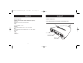
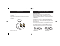
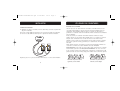
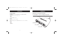
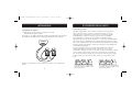
P74242ea-F1DK102P-man.qxd
01-04-2003
16:18
Page 1
En
Fr
OMNICUBE 2-Port Switch with Built-In Cabling
Switch OMNICUBE 2 Ports avec Câbles Intégrés
OMNICUBE 2-fach Switch mit integrierter Kabelgarnitur
OMNICUBE 2-poorts switch met geïntegreerde kabels
OMNICUBE Conmutador de 2 puertos
con cableado incorporado
Switch a 2 porte OMNICUBE con cablaggio incorporato
Control two computers using
one video monitor, and a PS/2
keyboard and mouse
Contrôler deux ordinateurs avec un
écran, un clavier et une souris PS/2
Kontrollieren Sie zwei Computer mit einem
Monitor und einer PS/2-Tastatur und -Maus
Beheer twee computers met slechts
één monitor, PS/2-toetsenbord en muis
Controla dos ordenadores utilizando
un monitor de vídeo, un teclado PS/2 y un ratón
Per permettere di utilizzare due computer mediante un
singolo monitor, tastiera PS/2 e mouse
User Manual
Manuel de l’utilisateur
Benutzerhandbuch
Handleiding
Manual de Usuario
Manuale dell’utente
F1DK102P
De
Nl
Es
It
P74242ea-F1DK102P-man.qxd
01-04-2003
16:19
Page 2
OMNICUBE 2-Port Switch
with Built-In Cabling
Control two computers using one video monitor,
and a PS/2 keyboard and mouse
User Manual
F1DK102P
P74242ea-F1DK102P-man.qxd
01-04-2003
16:19
Page 4
TABLE OF CONTENTS
Overview
Feature Overview . . . . . . . . .
Operating Systems . . . . . . . .
Unit Display Diagram . . . . . . .
Installation
Pre-Configuration . . . . . . . . .
Step-By-Step Installation Guide
. . . . . . . . . . . . . . . . . . . . . . . . . . . . .1
. . . . . . . . . . . . . . . . . . . . . . . . . . . . .2
. . . . . . . . . . . . . . . . . . . . . . . . . . . . .3
. . . . . . . . . . . . . . . . . . . . . . . . . . . . .4
. . . . . . . . . . . . . . . . . . . . . . . . . . . . .5
Using Your Switch
Powering Up the Systems . . . . . . . . . . . . . . . . . . . . . . . . . . . . . . . . .7
AutoScan Mode . . . . . . . . . . . . . . . . . . . . . . . . . . . . . . . . . . . . . . .8
OVERVIEW
The Belkin 2-Port KVM Switch with Built-In Cabling allows you to control multiple
computers with one keyboard, monitor, and mouse. The Switch supports PS/2 input
devices (keyboard and mouse), VGA, SVGA, XGA, and PS/2 computers.
Feature Overview
Complete Compact Solution
Built-in cables and color-coded connectors make operation and organization easy.
Hot Keys
Hot keys allow you to select ports using designated key commands. Control multiple
computers using a simple hot key sequence on your keyboard.
AutoScan
The AutoScan feature allows you to automatically scan and monitor the activities
of all operating computers connected to your Switch one by one.
Video Resolution
The Switch is able to support video resolutions of up to 2048x1536@65Hz. To
preserve signal integrity at high resolutions, 75-Ohm coaxial VGA cabling is
built-in to your Switch.
Light-Emitting Diode Display
LEDs on the top of the Switch function as status monitors. The LEDs light to
indicate which corresponding monitor port is currently active.
1
P74242ea-F1DK102P-man.qxd
01-04-2003
16:19
Page 2
OVERVIEW
Operating Systems
OVERVIEW
Unit Display Diagram
Your Switch is for use on CPUs using:
Platforms
• Windows® 95, 98, 2000, Me, NT®, XP
• DOS
• Linux®
• Novell® NetWare® 4.x/5.x
The 2-Port KVM Switch with Built-In Cabling:
Port Status
Indicator LEDs
Built-In Cables
Keyboards
• Supports 101-, 102-, and 104-key keyboards
Mice
• Microsoft® system-compatible PS/2 mice with 2, 3, 4, or 5 buttons
Monitors
• VGA
• SVGA
• MultiSync®
Console
Mouse Port
Console VGA
Monitor Ports
Console
Keyboard Port
2
3
P74242ea-F1DK102P-man.qxd
01-04-2003
16:19
Page 4
INSTALLATION
INSTALLATION
Pre-Configuration
Step-by-Step Installation Guide
Where to Place the Switch
The Switch is designed for positioning on the desktop. The exact placement will
be based on the location of your CPUs and length of your cables.
This section provides complete instructions for the hardware setup of a
single Switch.
Cable Distance Requirements
For PS/2 computers: VGA signals are best retained when transmitted up to eight
feet. Beyond eight feet, probability of video degradation increases with an
increase in distance. For this reason, your PS/2 computer should be placed
within eight feet of the KVM Switch.
Before attempting to connect anything to the Switch or to any computer, make
sure that everything is powered off. Plugging and unplugging cables while
computers are powered on can cause irreversible damage to your computers,
data, and/or to the Switch. Belkin Corporation will not be responsible for damage
caused in this way.
Note: If your computer needs to be more than eight feet from the KVM Switch, you
can use the Belkin CAT5 Extender (part number F1D084) to extend your PS/2
keyboard, PS/2 mouse, and monitor up to 500 feet (152.4m) away using a
standard CAT5 UTP cable.
Connecting the Console
Cautions and Warnings
Avoid placing cables near fluorescent lights, air conditioning equipment, or
machines that create electrical noise (e.g., vacuum cleaners).
Important Note
1. Power down all computers.
2. Connect your PS/2-type keyboard
and mouse to the KEYBOARD and
MOUSE ports located on the front
panel of your Switch.
3. Take the VGA cable that is
attached to your monitor and
connect it to the VGA port on the
front panel of the Switch.
4
5
P74242ea-F1DK102P-man.qxd
01-04-2003
16:19
Page 6
INSTALLATION
USING YOUR SWITCH
Connecting the Computer
Powering Up the Systems
1. Using the attached cables, take the VGA cable and connect it to
the VGA port on the first computer.
Once all cables have been connected, power up your CPUs that are attached to
the Switch. All computers can be powered on simultaneously. The Switch
emulates a mouse and keyboard on each port and will allow your computer to
boot normally. Your Switch should now be ready for use.
2. Connect the PS/2 keyboard KVM cable to the keyboard port on
the computer.
3. Connect the PS/2 mouse KVM cable to the mouse port on
the computer.
You can select which computer to operate through hot key commands. Note that
it will take 1-2 seconds for the video to display after switching. This is due to
the refresh of the video signal. A re-synchronization of the mouse and keyboard
signal also takes place. This is normal operation and ensures that proper
synchronization is established.
You can conveniently change ports on the Switch through a keyboard command
sequence using the “SCROLL LOCK” key and up and down arrow keys. To send
commands to the Switch, press the “SCROLL LOCK” key twice within two seconds.
You will hear a beep for confirmation. Then you can press the up or down arrow
keys to switch between ports.
Repeat Steps 1 through 3 for the additional computer to be connected to
the Switch.
6
Switch to next active port,
up arrow
Switch to previous active port,
down arrow
7
P74242ea-F1DK102P-man.qxd
01-04-2003
16:19
Page 8
USING YOUR SWITCH
You can switch directly to any port by entering the Switch port number you wish
to use. For example, if you press “SCROLL LOCK”, “SCROLL LOCK”, “2”, the
computer on port 2 will be selected.
+
+
Switch to Port 2—(2)
AutoScan Mode
In AutoScan mode, the Switch remains on one port for eight seconds before
switching to the next. This time interval cannot be changed.
To enable AutoScan mode, press “SCROLL LOCK”, “SCROLL LOCK”, “S”.
Note: There is no mouse or keyboard control in this mode by design, in order to
prevent errors. If it were enabled, the user could move the mouse or use the
keyboard while the KVM Switch is switching to the next port. This could interrupt
communication between the computer and Switch that might cause erratic mouse
movement, or result in errant display of characters when using the keyboard.
To disable AutoScan mode, press the space bar.
8
P74242ea-F1DK102P-man.qxd
01-04-2003
16:19
Page 10
Belkin Corporation
501 West Walnut Street
Compton • CA • 90220 • USA
Tel: +1 310.898.1100
Fax: +1 310.898.1111
Belkin Components, Ltd.
Express Business Park • Shipton Way • Rushden
NN10 6GL • United Kingdom
Tel: +44 (0) 1933 35 2000
Fax: +44 (0) 1933 31 2000
Belkin Components B.V.
Starparc Building • Boeing Avenue 333
1119 PH Schiphol-Rijk • The Netherlands
Tel: +31 (0) 20 654 7300
Fax: +31 (0) 20 654 7349
Switch OMNICUBE 2 Ports
avec Câbles Intégrés
Contrôler deux ordinateurs avec un écran,
un clavier et une souris PS/2
Belkin GmbH
Hanebergstrasse 2
80637 München • Germany
Tel.: +49 (0) 89 1434050
Fax: +49 (0) 89 143405100
Belkin Tech Support
US:
Europe:
Australia:
+1 310.898.1100 ext. 2263
+1 800.223.5546 ext. 2263
00 800 223 55 460
1800 666 040
P74242
© 2003 Belkin Corporation. All rights reserved.
All trade names are registered trademarks of respective manufacturers listed.
Guide de l’Utilisateur
F1DK102P
P74242ea-F1DK102P-man.qxd
01-04-2003
16:19
Page 12
SOMMAIRE
Vue d’Ensemble
Vue d’Ensemble des Caractéristiques .
Systèmes d’Exploitation . . . . . . . . .
Diagramme de l’Affichage . . . . . . . .
Installation
Pré-configuration . . . . . . . . . . . . .
Manuel d’Installation Étape par Étape
. . . . . . . . . . . . . . . . . . . . . . . . .1
. . . . . . . . . . . . . . . . . . . . . . . . .2
. . . . . . . . . . . . . . . . . . . . . . . . .3
. . . . . . . . . . . . . . . . . . . . . . . . .4
. . . . . . . . . . . . . . . . . . . . . . . . .5
Utiliser votre Switch
Mettre les Systèmes en Marche . . . . . . . . . . . . . . . . . . . . . . . . . . . . .7
Mode AutoScan . . . . . . . . . . . . . . . . . . . . . . . . . . . . . . . . . . . . . . .8
VUE D’ENSEMBLE
Le Switch KVM 2 Ports avec Câbles Intégrés de Belkin vous permet de contrôler plusieurs
ordinateurs avec un seul clavier, écran et souris. Le Switch prend en charge des
périphériques d’entrée (clavier et souris) et des ordinateurs VGA, SVGA, XGA et PS/2.
Vue d’Ensemble des Caractéristiques
Une Solution Complète
et Compacte de câbles intégrés et de connecteurs à code de couleurs rendent le
fonctionnement et l’organisation simple.
Touches de Raccourci
Les touches de raccourci vous permettent de sélectionner les ports en utilisant des
commandes clavier. Contrôlez plusieurs ordinateurs d’une simple commande clavier.
AutoScan
La fonction AutoScan vous permet de scanner automatiquement et de surveiller
les activités des ordinateurs utilisés connectés à votre Switch, un par un.
Résolution Vidéo
Le Switch est capable de prendre en charge des résolutions vidéo allant jusqu’à
2048x1536 @65Hz. Afin de préserver l’intégrité du signal à de hautes
résolutions, un câble coaxial VGA 75 Ohm est intégré à votre Switch.
Affichage à Diodes Électroluminescentes (LED)
Les LED sur le haut du Switch contrôlent les écrans. Les LED indiquent
quel port d’écran est actuellement actif.
1
P74242ea-F1DK102P-man.qxd
01-04-2003
16:19
Page 2
VUE D’ENSEMBLE
Systèmes d’Exploitation
VUE D’ENSEMBLE
Diagramme de l’Affichage
Votre Switch est utilisé sur des ordinateurs fonctionnant sous :
Plateformes
• Windows® 95, 98, 2000, Me, NT®, XP
• DOS
• Linux®
• Novell® NetWare® 4.x/5.x
Le Switch KVM 2 Ports avec Câbles Intégrés
Statut des Ports
Diodes de Contrôle
Câbles Intégrés
Claviers
• Prend en charge les claviers 101, 102 et 104
Souris
• Souris compatible avec les systèmes Microsoft® PS/2 avec 2,3,4 ou 5 boutons
Écrans
• VGA
• SVGA
• MultiSync®
Console
Port Souris
Console VGA
Ports Écran
Console
Port Clavier
2
3
P74242ea-F1DK102P-man.qxd
01-04-2003
16:19
Page 4
INSTALLATION
INSTALLATION
Pré-Configuration
Manuel D’Installation Étape par Étape
Où installer le Switch
Le Switch est conçu pour être placé sur le bureau. L’emplacement exact sera basé
par rapport à l’endroit où se trouve vos ordinateurs et par rapport à la longueur
de vos câbles.
Cette section vous donne des instructions complètes pour l’installation matérielle
d’un seul Switch.
Distance de Câblage Nécessaire
Pour les ordinateurs PS/2 : Les signaux VGA sont mieux conservés lorsqu’ils sont
transmis jusqu’à un maximum de 2,40m. Au-delà de 2,40m, la probabilité de
dégradation vidéo augmente avec une distance plus longue. Pour cette raison,
votre ordinateur PS/2 doit être placé à une distance maximum de 2,40m du
Switch KVM.
Note : Si votre ordinateur doit être situé à plus de 2,40m du Switch KVM, vous
avez la possibilité d’utiliser le Prolongateur CAT5 de Belkin (référence produit
F1D084) pour prolonger votre clavier PS/2, souris PS/2 et écran à une distance
allant jusqu’à 152,40m en utilisant un câble UTP CAT5 standard.
Conseils et Avertissements
Évitez de placer les câbles près de lumières fluorescentes, d’équipement de
climatisation ou de machines générant des bruits électriques (par exemple
aspirateurs).
4
Important :
Avant d’essayer de connecter quoi que ce soit au Switch ou à un ordinateur,
vérifiez que tout est éteint. Connecter et déconnecter les câbles lorsque les
ordinateurs sont en marche peut causer des dommages irréversibles à vos
ordinateurs, données et/ou au Switch. Belkin Corporation n’est pas responsable
de tout dommage causé comme tel.
Connecter la Console
1. Éteindre tous les ordinateurs.
2. Connectez votre clavier et souris
PS/2 aux ports CLAVIER et SOURIS
situés sur le devant de votre
Switch.
3. 3. Prenez le câble VGA qui est
relié à votre écran et connectez
le au port VGA sur le devant
du Switch.
5
P74242ea-F1DK102P-man.qxd
01-04-2003
16:19
Page 6
INSTALLATION
UTILISER VOTRE SWITCH
Connecter l’Ordinateur
Mettre en Marche les Systèmes
1. En utilisant les câbles reliés, prenez le câble VGA et connectez
le au port VGA de votre ordinateur.
Une fois que les câbles sont connectés, mettez en marche vos UC qui sont reliées
au Switch. Tous les ordinateurs peuvent être allumés simultanément. Le Switch
émule les signaux de la souris et du clavier sur chaque port et permettra à
l’ordinateur de démarrer normalement. Votre Switch devrait maintenant être prêt
à l’utilisation.
2. Connectez le câble KVM Clavier PS/2 au port clavier de l’ordinateur.
3. Connectez le câble KVM Souris PS/2 au port souris de l’ordinateur.
Vous pouvez sélectionner l’ordinateur que vous souhaitez utiliser par des
raccourcis clavier. Notez qu’il faut 1 à 2 secondes pour que l’affichage se fasse
après la permutation. Ceci est dû à l’actualisation du signal vidéo. Le signal de la
souris et du clavier est également re-synchronisé. Ce fonctionnement est normal
et garantit un synchronisation correcte.
Vous pouvez aisément changer de ports sur le Switch avec un raccourci clavier en
utilisant la touche “SCROLL LOCK” et les touches de direction. Pour envoyer les
commandes au Switch, tapez sur la touche “SCROLL LOCK” deux fois en l’espace
de deux secondes. Vous entendrez un bip de confirmation. Vous pouvez ensuite
utiliser les touches de direction pour changer de ports.
Répétez les Étapes 1, 2 et 3 pour les ordinateurs supplémentaires qui doivent
être connectés au Switch.
6
Passer au port actif suivant,
touche de direction Haut
Passer au port actif précédent,
touche de direction Bas
7
P74242ea-F1DK102P-man.qxd
01-04-2003
16:19
Page 8
UTILISER VOTRE SWITCH
Vous pouvez changer de port directement en tapant le numéro du port que vous
souhaitez utiliser. Par exemple, si vous tapez “SCROLL LOCK”, “SCROLL LOCK”,
“2”, l’ordinateur relié au port 2 sera sélectionné.
+
+
Passer au Port 2-(2)
Mode AutoScan
En Mode AutoScan, le Switch reste sur un port pendant huit secondes avant de
passer au suivant. L’intervalle de temps ne peut pas être modifié.
Pour activer le mode AutoScan, tapez “SCROLL LOCK”, “SCROLL LOCK”, “S”.
Note : Afin d’éviter des erreurs, il n’y a pas de contrôle clavier ou souris dans ce
mode. Si le contrôle était activé, l’utilisateur aurait la possibilité de bouger la
souris ou d’utiliser le clavier pendant que le Switch passe à un autre port. Cela
pourrait interrompre la communication entre l’ordinateur et le Switch qui peut
rendre le mouvement de la souris instable ou bien résulter de l’affichage aléatoire
de caractères lors de l’utilisation du clavier.
Pour désactiver le mode AutoScan, appuyez sur la barre d’espace.
8
P74242ea-F1DK102P-man.qxd
01-04-2003
16:19
Page 10
Belkin Corporation
501 West Walnut Street
Compton • CA • 90220 • USA
Tel: +1 310.898.1100
Fax: +1 310.898.1111
Belkin Components, Ltd.
Express Business Park • Shipton Way • Rushden
NN10 6GL • Royaume-Uni
Tel: +44 (0) 1933 35 2000
Fax: +44 (0) 1933 31 2000
Belkin Components B.V.
Starparc Building • Boeing Avenue 333
1119 PH Schiphol-Rijk • Pays-Bas
Tel: +31 (0) 20 654 7300
Fax: +31 (0) 20 654 7349
OMNICUBE 2-fach Switch
mit integrierter Kabelgarnitur
Kontrollieren Sie zwei Computer mit einem Monitor
und einer PS/2-Tastatur und -Maus
Belkin GmbH
Hanebergstrasse 2
80637 München • Allemagne
Tel.: +49 (0) 89 1434050
Fax: +49 (0) 89 143405100
Assistance technique Belkin
USA:
Europe:
Australia:
+1 310.898.1100 poste 2263
+1 800.223.5546 poste 2263
00 800 223 55 460
1800 666 040
P74242
© 2003 Belkin Corporation. Tous droits réservés.
Tous les noms de marque sont des marques déposées des fabricants respectifs énumérés.
Benutzerhandbuch
F1DK102P
P74242ea-F1DK102P-man.qxd
01-04-2003
16:19
Page 12
INHALT
Übersicht
Merkmale . . . . . . . . . . . . . . . . . . . . .
Betriebssysteme . . . . . . . . . . . . . . . . .
Funktionsübersicht . . . . . . . . . . . . . . .
Installation
Vorbereitung des Geräts . . . . . . . . . . . .
Einzelschrittanweisungen zur Installation
ÜBERSICHT
. . . . . . . . . . . . . . . . . . . . . .1
. . . . . . . . . . . . . . . . . . . . . .2
. . . . . . . . . . . . . . . . . . . . . .3
Mit dem 2fach-Masterswitch mit integrierter Kabelgarnitur von Belkin können Sie
mehrere Computer mit einer Tastatur, einem Bildschirm und einer Maus steuern. Der
Switch unterstützt PS/2-Eingabegeräte (Tastatur und Maus), die Grafikstandards
VGA, SVGA, XGA und PS/2-Computer.
Merkmale
. . . . . . . . . . . . . . . . . . . . . .4
. . . . . . . . . . . . . . . . . . . . . .5
Ihren Switch verwenden
Hochfahren der Computer . . . . . . . . . . . . . . . . . . . . . . . . . . . . . . . . .7
AutoScan-Betrieb . . . . . . . . . . . . . . . . . . . . . . . . . . . . . . . . . . . . . .8
Komplette Kompaktlösung
Integrierte Kabel und farbcodierte Anschlüsse vereinfachen die Bedienung und die
Organisation.
Hotkeys
Die Auswahl der Ports erfolgt mit Hilfe von Tastenbefehlen über die Tastatur.
Steuern Sie mehrere Computer mit einer einfachen Tastenfolge auf der Tastatur.
AutoScan
Mit der AutoScan-Funktion können Sie die Aktivitäten aller betriebsbereiten
Computer, die am Switch angeschlossen sind, automatisch abfragen und
überwachen.
Bildschirmauflösung
Der Switch unterstützt Auflösungen von bis zu 2048 x 1536 bei 65 Hz. Damit bei
hoher Auflösung die Signalintegrität gesichert bleibt, ist Ihr Switch mit einem
75-Ω-VGA-Koaxialkabel ausgestattet.
LEDs
Die LEDs auf der Oberseite des Switches dienen der Statusanzeige. Die LEDs
leuchten, um anzuzeigen, welcher Bildschirm-Port gerade aktiviert ist.
1
P74242ea-F1DK102P-man.qxd
01-04-2003
16:19
Page 2
ÜBERSICHT
Betriebssysteme
ÜBERSICHT
Funktionsübersicht
Ihr Switch ist für folgende Computer-Plattformen ausgelegt:
Plattformen
• Windows® 95, 98, 2000, Me, NT® und XP
• DOS
• Linux®
• Novell® NetWare® 4.x/5.x
2fach-Masterswitch mit integrierter Kabelgarnitur:
Port-Status-LEDs
Integrierte Kabelgarnitur
Tastaturen
• Unterstützt Tastaturen mit 101 / 102 / 104 Tasten
Mäuse
• PS/2-kompatible Microsoft®-Mäuse mit 2, 3, 4 oder 5 Tasten
Bildschirm
• VGA
• SVGA
• MultiSync®
Konsole Maus-Port
Konsolen-VGABildschirmanschlüsse
KonsolenTastaturanschluss
2
3
P74242ea-F1DK102P-man.qxd
01-04-2003
16:19
Page 4
INSTALLATION
INSTALLATION
Vorbereitung des Geräts
Einzelschrittanweisungen zur Installation
Aufstellungsort
Der Switch ist für die Aufstellung auf einem Tisch ausgelegt. Der exakte
Aufstellungsort ist abhängig von der Position Ihrer Computer und der Länge Ihrer
Kabel.
In diesem Abschnitt wird die Hardware-Installation eines Einzel-Switches
beschrieben.
Zulässige Kabellängen
Für PS/2-Computer: VGA-Signale werden am besten über Entfernungen von bis zu
2,5 m übertragen. Bei größeren Abständen kann sich die Bildqualität in Relation
zum zunehmenden Abstand verschlechtern. Daher sollte Ihr PS/2-Computer
maximal 2,5 m von Ihrem Masterswitch entfernt sein.
Hinweis: Werden größere Abstände gewünscht, benötigen Sie eine Belkin-CAT5Verlängerung (Artikelnr.: F1D084). Mit diesem Zubehör können Sie über ein
standardmäßiges CAT5-UTP-Kabel Bildschirm, PS/2-Tastatur und PS/2-Maus bis zu
150 m entfernt aufstellen.
Warnhinweis
Kabel sollten nicht in der Nähe von fluoreszierenden Lichtquellen, Klimaanlagen
oder Geräten, die elektrische Störeinflüssen hervorrufen (z.B. Staubsauger)
verlegt werden.
4
Wichtige Hinweise
Bevor Sie Geräte an den Switch oder einen der Computer anschließen, müssen Sie
unbedingt alle Einheiten ausschalten. Das Anschließen oder Herausziehen von
Kabeln bei eingeschalteten Computern kann zu irreparablen Schäden an Ihren
Computern, an Daten bzw. am Switch führen. Belkin Corporation übernimmt
keinerlei Haftung für derart verursachte Schäden.
Überprüfen der Konsole
1. Schalten Sie alle Computer ab.
2. Schließen Sie Ihre PS/2-Tastatur
und die PS/2-Maus an die
Schnittstellen KEYBOARD
(Tastatur) und MOUSE (Maus) an
der Vorderseite des Switches an.
3. Schließen Sie das VGA-Kabel
Ihres Monitors an den VGA-Port an
der Vorderseite des Switches an.
5
P74242ea-F1DK102P-man.qxd
01-04-2003
16:19
Page 6
INSTALLATION
IHREN SWITCH VERWENDEN
Anschließen des Computers
Hochfahren der Computer
1. Schließen Sie das angeschlossene VGA-Kabel an den VGA-Port am ersten
Computer an.
Sobald alle Kabel angeschlossen sind, können Sie die an den Switch
angeschlossenen Computer hochfahren. Alle Computer können gleichzeitig
eingeschaltet werden. Der Switch emuliert an jedem Port eine Maus und eine
Tastatur und ermöglicht Ihrem Computer einen normalen Systemstart. Ihr Switch
ist jetzt einsatzbereit.
2. Schließen Sie das PS/2-Masterswitch-Tastaturkabel an den Tastatur-Port des
Computers an.
3. Schließen Sie das PS/2-Masterswitch-Mauskabel an den Maus-Port des
Computers an.
Sie können mit Hilfe von Tastaturbefehlen auswählen, welchen Computer Sie
bedienen möchten. Bitte beachten Sie, dass es ein bis zwei Sekunden dauert, bis
die Bildschirmanzeige wechselt, da die Bildschirmsignale aktualisiert werden
müssen. Außerdem werden Maus- und Tastatursignal neu synchronisiert. Dies ist
die normale Auswirkung einer Funktion, die für eine ordnungsgemäße
Synchronisierung sorgt.
Sie können mit einer einfachen Tastenfolge bequem zwischen den Schnittstellen
am Switch wechseln, verwenden Sie hierzu die Taste Rollen und die obere und
untere Pfeiltaste. Um Befehle an den Switch zu senden, müssen Sie die RollenTaste innerhalb von zwei Sekunden zweimal drücken. Dies wird durch einen
Signalton bestätigt. Danach können Sie mit der oberen und unteren Pfeiltaste
zwischen den beiden Ports umschalten.
Wiederholen Sie die Schritte 1 bis 3 für weitere Computer, die an den Switch
angeschlossen werden sollen.
6
Nächster aktiver Port:
Pfeil-nach-oben
Vorheriger aktiver Port:
Pfeil-nach-unten
7
P74242ea-F1DK102P-man.qxd
01-04-2003
16:19
Page 8
IHREN SWITCH VERWENDEN
Sie können direkt zu einem bestimmten Port schalten, indem Sie die Nummer des
Switch-Ports eingeben. Wenn Sie z.B. die Rollen-Taste, die Rollen-Taste und die
Taste 2 drücken, wird der Computer an Port 2 ausgewählt.
+
+
Umschalten zu Port 2: (2)
AutoScan-Betrieb
Im AutoScan-Modus verbleibt der Masterswitch 8 Sekunden lang an einem Port,
bevor er zum nächsten schaltet. Dieses Intervall kann nicht geändert werden.
Drücken Sie die Rollen-Taste, die Rollen-Taste und die Taste S, um den AutoScanModus zu aktivieren.
Hinweis: Um Fehler zu vermeiden, ist in diesem Modus absichtlich die Maus und die
Tastatur deaktiviert. Wenn sie aktiviert wären, könnte der Benutzer die Maus
bewegen oder die Tastatur verwenden, während der Masterswitch zum nächsten Port
schaltet. Das könnte die Datenübertragung zwischen dem Computer und dem Switch
unterbrechen, was zu fehlerhaften Mausbewegungen oder falschen Tastatureingaben
führen könnte.
Um den AutoScan-Modus zu beenden, drücken Sie die Leertaste.
8
P74242ea-F1DK102P-man.qxd
01-04-2003
16:19
Page 10
Belkin Corporation
501 West Walnut Street
Compton • CA • 90220 • USA
Tel: +1 310.898.1100
Fax: +1 310.898.1111
Belkin Components, Ltd.
Express Business Park • Shipton Way • Rushden
NN10 6GL • Großbritannien
Tel: +44 (0) 1933 35 2000
Fax: +44 (0) 1933 31 2000
Belkin Components B.V.
Starparc Building • Boeing Avenue 333
1119 PH Schiphol-Rijk • Niederlande
Tel: +31 (0) 20 654 7300
Fax: +31 (0) 20 654 7349
OMNICUBE 2-poorts switch
met geïntegreerde kabels
Beheer twee computers met slechts
één monitor, PS/2-toetsenbord en muis
Belkin GmbH
Hanebergstrasse 2
80637 München • Deutschland
Tel.: +49 (0) 89 1434050
Fax: +49 (0) 89 143405100
Belkin-Kundendienst
USA:
Europa:
Australien:
+1 310.898.1100 Durchwahl: 2263
+1 800.223.5546 Durchwahl: 2263
00 800 223 55 460
1800 666 040
P74242
© 2003 Belkin Corporation. Alle Rechte vorbehalten.
Alle Warenzeichen sind eingetragene Warenzeichen der angegebenen Hersteller.
Handleiding
F1DK102P
P74242ea-F1DK102P-man.qxd
01-04-2003
16:19
Page 12
INHOUDSOPGAVE
Overzicht
Overzicht productkenmerken
Besturingssystemen . . . . .
Apparaatoverzicht . . . . . . .
Installeren
Voorbereidingen . . . . . . . .
Stap-voor-stap installeren .
. . . . . . . . . . . . . . . . . . . . . . . . . . . . . . .1
. . . . . . . . . . . . . . . . . . . . . . . . . . . . . . .2
. . . . . . . . . . . . . . . . . . . . . . . . . . . . . . .3
. . . . . . . . . . . . . . . . . . . . . . . . . . . . . . .4
. . . . . . . . . . . . . . . . . . . . . . . . . . . . . . .5
De switch gebruiken
De computers inschakelen . . . . . . . . . . . . . . . . . . . . . . . . . . . . . . . .7
AutoScan-functie . . . . . . . . . . . . . . . . . . . . . . . . . . . . . . . . . . . . . .8
OVERZICHT
Met een 2-poorts kvm-switch van Belkin met geïntegreerde kabels kunt u twee
computers bedienen met één toetsenbord, monitor en muis. De switch ondersteunt
PS/2-invoerapparaten (toetsenbord en muis), VGA, SVGA, XGA en PS/2-computers.
Overzicht productkenmerken
Complete, compacte oplossing
Met ingebouwde kabels en gekleurde aansluitingen voor een optimaal
gebruiksgemak.
Sneltoetsen
Via speciale sneltoetsen kiest u snel de gewenste poort. Bedien verschillende
computers via eenvoudige sneltoetscombinaties op het toetsenbord.
AutoScan-functie
De AutoScan-functie scant automatisch de op de switch aangesloten computers
één voor één op activiteit.
Beeldresolutie
De switch ondersteunt beeldresoluties tot 2048x1536 op 65 Hz. De switch is
voorzien van 75 ohm VGA-coaxkabels voor optimale signaaldoorgifte bij hoge
resoluties.
LED-controlelampjes
LED's boven op de switch geven de actuele toestand weer. De LED van de actieve
monitorpoort licht op.
1
P74242ea-F1DK102P-man.qxd
01-04-2003
16:19
Page 2
OVERZICHT
Besturingssystemen
OVERZICHT
Apparaatoverzicht
De switch is geschikt voor computers met:
Besturingssysteem
• Windows® 95, 98, 2000, Me, NT®, XP
• DOS
• Linux®
• Novell® NetWare® 4.x/5.x
2-poorts kvm-switch met geïntegreerde kabels:
Indicatielampjes
poortstatus
Geïntegreerde kabels
Toetsenbord
• Met 101, 102 of 104 toetsen
Muis
• Microsoft®-compatibele PS/2-muis met 2, 3, 4 of 5 knoppen
Monitor
• VGA
• SVGA
• MultiSync®
Muis-consolepoort
VGA-monitor
consolepoorten
Toetsenbordconsolepoort
2
3
P74242ea-F1DK102P-man.qxd
01-04-2003
16:19
Page 4
INSTALLEREN
INSTALLATION
INSTALLEREN
Voorbereidingen
Stap-voor-stap installeren
De plaats van de switch
De switch is bedoeld om op uw bureau te worden gezet. Waar u hem het beste
kunt neerzetten hangt af van de plaats van uw computers en de lengte van de
kabels.
Dit hoofdstuk geeft een volledige beschrijving van het installeren van een
switch.
Kabellengte-eisen
Voor PS/2-computers: Via een kabel kunnen VGA-signalen maximaal 2,4 meter
worden doorgegeven. Bij grotere kabellengten zal de kwaliteit van het
videosignaal verminderen met de afstand. Plaats uw PS/2-computer daarom op
maximaal 2,4 m afstand van de kvm-switch.
Let op: Is de afstand tussen uw computer en de kvm-switch groter dan 2,4 m,
gebruik dan de Belkin CAT5 Extender (artikelnr. F1D084) om uw PS/2-toetsenbord,
PS/2-muis en monitor tot 150 m ver weg te kunnen plaatsen met behulp van een
normale CAT5 UTP-kabel.
Waarschuwingen
Houd de kabels uit de buurt van TL- en spaarlampen, airconditioners en machines
die elektrische storingen veroorzaken (zoals stofzuigers).
Let op, belangrijk
Schakel alle apparaten uit voordat u iets probeert aan te sluiten op de switch of
op een computer. Het aansluiten en loshalen van kabels bij ingeschakelde
computers kan uw computers, uw gegevens en/of de switch permanent
beschadigen. Belkin Corporation is niet aansprakelijk voor enige schade die op
die manier is ontstaan.
De console aansluiten
1. Schakel alle computers uit.
2. Sluit de PS/2-stekkers van het
toetsenbord en de muis aan op de
poorten KEYBOARD (toetsenbord)
en MOUSE (muis) aan de voorkant
van de switch.
3. Sluit de VGA-kabel van uw
monitor aan op de VGA-poort aan
de voorkant van de switch.
4
5
P74242ea-F1DK102P-man.qxd
01-04-2003
16:19
Page 6
INSTALLEREN
DE SWITCH GEBRUIKEN
De computer aansluiten
De computers inschakelen
1. Gebruik de geïntegreerde kabels en sluit de VGA-kabel aan op de VGA-poort
van de eerste computer.
Sluit eerst alle kabels aan, en schakel daarna pas de computers in die u op de
switch heeft aangesloten. U mag alle computers tegelijk inschakelen. De switch
emuleert een muis en een toetsenbord voor elke poort, zodat alle computers
normaal zullen opstarten. De switch is nu klaar voor gebruik.
2. Sluit de PS/2-toetsenbordkabel van de kvm-switch aan op de
toetsenbordaansluiting van de computer.
3. Sluit de PS/2-muiskabel van de kvm-switch aan op de muispoort van de
computer.
Via sneltoetscommando's kunt u selecteren welke computer u wilt bedienen. Houd
er rekening mee dat het gekozen beeld pas 1-2 seconden na het omschakelen op
de monitor zal verschijnen. Dit komt door de verversingssnelheid van het
videosignaal. Ook zullen de signalen van de muis en het toetsenbord opnieuw
worden gesynchroniseerd. Dit is de normale procedure die zorgt voor een
probleemloze omschakeling.
U kunt ook via het toetsenbord een andere switch-poort kiezen met een
combinatie van de “SCROLL LOCK”-toets en de pijltjestoetsen voor omhoog en
omlaag. Stuur een commando naar de switch door binnen twee seconden twee
keer op de “SCROLL LOCK”-toets te drukken. Ter bevestiging hoort u een piepje.
Vervolgens kunt u met de pijltjestoetsen voor omhoog en omlaag een andere
poort kiezen.
Herhaal de stappen 1 t/m 3 voor de andere computer die u op de switch wilt
aansluiten.
6
Met 'pijltje omhoog' kiest u de
volgende actieve poort
Met 'pijltje omlaag' kiest u de
vorige actieve poort
7
P74242ea-F1DK102P-man.qxd
01-04-2003
16:19
Page 8
DE SWITCH GEBRUIKEN
Of u kunt direct het gewenste poortnummer kiezen. Druk bijvoorbeeld op “SCROLL
LOCK”, “SCROLL LOCK” en op “2” om de computer te selecteren die op poort 2 is
aangesloten.
+
+
Omschakelen naar poort 2—(2)
AutoScan-functie
Bij ingeschakelde AutoScan-functie activeert de switch acht seconden lang een
poort, en schakelt dan om naar de volgende. U kunt deze periode niet zelf
wijzigen.
U schakelt de AutoScan-functie in met “SCROLL LOCK”, “SCROLL LOCK” en “S”.
Let op: Als deze functie is ingeschakeld zullen de muis en het toetsenbord niet
werken, om fouten te voorkomen. Zouden ze wel zijn ingeschakeld, dan zou u
tijdens het omschakelen per ongeluk de muis kunnen verplaatsen of het
toetsenbord kunnen bedienen. Dit kan de communicatie tussen de computer en de
switch verstoren, wat vreemde cursorverplaatsingen of rare letters kan opleveren.
Druk op de spatiebalk om de AutoScan-functie uit te schakelen.
8
P74242ea-F1DK102P-man.qxd
01-04-2003
16:19
Page 10
Belkin Corporation
501 West Walnut Street
Compton • CA • 90220 • USA
Tel: +1 310.898.1100
Fax: +1 310.898.1111
Belkin Components, Ltd.
Express Business Park • Shipton Way • Rushden
NN10 6GL • Verenigd Koningrijk
Tel: +44 (0) 1933 35 2000
Fax: +44 (0) 1933 31 2000
Belkin Components B.V.
Starparc Building • Boeing Avenue 333
1119 PH Schiphol-Rijk • Nederland
Tel: +31 (0) 20 654 7300
Fax: +31 (0) 20 654 7349
OMNICUBE Conmutador
de 2 puertos con cableado
incorporado
Controla dos ordenadores utilizando
un monitor de vídeo, un teclado PS/2 y un ratón
Belkin GmbH
Hanebergstrasse 2
80637 München • Duitsland
Tel.: +49 (0) 89 1434050
Fax: +49 (0) 89 143405100
Belkin Tech Support
USA:
Europe:
Australia:
+1 310.898.1100 tstl. 2263
+1 800.223.5546 tstl. 2263
00 800 223 55 460
1800 666 040
P74242
© 2003 Belkin Corporation. Alle rechten voorbehouden.
Alle handelsnamen zijn geregistreerde handelsmerken van de betreffende rechthebbenden.
Manual de usuario
F1DK102P
P74242ea-F1DK102P-man.qxd
01-04-2003
16:19
Page 12
ÍNDICE
Descripción general
Características Descripción general . .
Sistemas operativos . . . . . . . . . . .
Diagrama de visualización del equipo
Instalación
Preconfiguración . . . . . . . . . . . . .
Guía de instalación paso a paso . . .
. . . . . . . . . . . . . . . . . . . . . . . . .1
. . . . . . . . . . . . . . . . . . . . . . . . .2
. . . . . . . . . . . . . . . . . . . . . . . . .3
. . . . . . . . . . . . . . . . . . . . . . . . .4
. . . . . . . . . . . . . . . . . . . . . . . . .5
Utilización de su conmutador
Encendido de los sistemas . . . . . . . . . . . . . . . . . . . . . . . . . . . . . . . .7
Modo AutoScan . . . . . . . . . . . . . . . . . . . . . . . . . . . . . . . . . . . . . . .8
DESCRIPCIÓN GENERAL
El Conmutador KVM de 2 puertos de Belkin con cableado incorporado le permite
controlar varios ordenadores con un teclado, monitor y ratón. El Conmutador admite
dispositivos de entrada PS/2 (teclado y ratón), VGA, SVGA, XGA y ordenadores PS/2.
Características Descripción general
Solución compacta completa:
Cables incorporados y conectores codificados mediante colores que facilitan el
funcionamiento y la organización.
Teclas de acceso rápido:
Las teclas de acceso rápido le permiten seleccionar puertos utilizando comandos de
teclas designados. Controla varios ordenadores utilizando una secuencia simple de
teclas de acceso rápido en su teclado.
AutoScan:
La característica AutoScan le permite explorar y monitorizar automáticamente las
actividades de todos los ordenadores en funcionamiento conectados a su
Conmutador uno a uno.
Resolución de vídeo:
El Conmutador admite resoluciones de vídeo de hasta 2048x1536@65Hz. Para
preservar la integridad de la señal a altas resoluciones, se incorpora un cable
coaxial VGA de 75 Ohmios en su Conmutador.
Indicadores LED en la parte superior del Conmutador:
Funcionan como monitores de estado. Los indicadores LED se iluminan para
indicar qué puerto del monitor correspondiente está actualmente activo.
1
P74242ea-F1DK102P-man.qxd
01-04-2003
16:19
Page 2
DESCRIPCIÓN GENERAL
Sistemas operativos
DESCRIPCIÓN GENERAL
Diagrama de visualización del equipo
Su Conmutador es para utilizar en CPU utilizando:
Plataformas
• Windows® 95, 98, 2000, Me, NT®, XP
• DOS
• Linux®
• Novell® NetWare® 4.x/5.x
Conmutador KVM de 2 puertos con cableado incorporado:
Indicadores LED del
estado del puerto
Cables incorporados
Teclados
• Admite teclados de 101, 102 y 104 teclas
Ratón
• Ratones PS/2 compatible con sistema Microsoft® con 2, 3, 4 o 5 botones
Monitores
• VGA
• SVGA
• MultiSync®
Consola
Puerto de ratón
Consola
Puerto del monitor VGA
Consola
Puerto de teclado
2
3
P74242ea-F1DK102P-man.qxd
01-04-2003
16:19
Page 4
INSTALACIÓN
INSTALLATION
INSTALACIÓN
Pre-configuración
Guía de instalación paso a paso
Donde colocar el Conmutador
El Conmutador está diseñado para colocare en un PC de sobremesa. El lugar
exacto se basará en la ubicación de su CPU y la longitud de sus cables.
Esta sección le proporciona instrucciones completas para la configuración del
hardware de un único Conmutador.
Requisitos de distancia del cable
Para ordenadores PS/2: Las señales VGA se pueden transmitir correctamente a una
distancia de hasta 8 pies (2 metros y medio). Más allá de los ocho pies,
probablemente disminuya la calidad de la señal de vídeo al aumentar la
distancia. Por esta razón, el ordenador con puerto PS/2 debe colocarse a menos
de ocho pies de distancia del Conmutador KVM.
Antes de conectar ningún dispositivo al Conmutador o a cualquiera de los
ordenadores, asegúrese de que todos los dispositivos estén apagados. La
conexión y desconexión de cables con los ordenadores encendidos podría producir
daños irreversibles en los ordenadores, datos y/o el Conmutador. Belkin
Corporation no se hace responsable de los daños causados de esta forma.
Nota: Si su ordenador debe instalarse a más de ocho pies de distancia del
Conmutador KVM podrá utilizar el prolongador Belkin CAT5 (número de pieza
F1D084) para prolongar su teclado PS/2, ratón PS/2 y monitor hasta una distancia
de 500 pies (152,4m) utilizando cable UTP CAT5 estándar.
Precauciones y Advertencias
Evite colocar los cables cerca de tubos fluorescentes, equipos de aire
acondicionado o máquinas que generen ruido eléctrico (por ejemplo:
aspiradores).
4
Nota importante
Conexión de la consola
1. Apague todos los ordenadores.
2. Conecte su teclado tipo PS/2 y el
ratón en los puertos del TECLADO y
el RATÓN localizados en el panel
frontal del Conmutador.
3. Tome el cable VGA que tiene
conectado al monitor y conéctelo
al puerto VGA del panel frontal del
Conmutador.
5
P74242ea-F1DK102P-man.qxd
01-04-2003
16:19
Page 6
INSTALACIÓN
UTILIZANDO SU CONMUTADOR
Conexión del ordenador
Encendido de los sistemas
1. Utilizando los cables conectados, tome el cable VGA y conéctelo al puerto VGA
del primer ordenador.
Una vez que todos los cables han sido conectados, encienda la CPU que está
conectada al Conmutador. Se pueden encender de forma simultánea todos los
ordenadores. El Conmutador emula un ratón y un teclado en cada puerto y
permitirá a su ordenador arrancar normalmente. Ahora estará listo su Conmutador
para ser utilizado.
2. Conecte el cable KVM del teclado PS/2 en el puerto del teclado del ordenador.
3. Conecte el cable KVM del ratón PS/2 en el puerto del ratón del ordenador.
Puede seleccionar qué ordenador funcionará mediante comandos de teclas
rápidas. Observe que la señal de vídeo tardará entre 1 y 2 segundos en aparecer
después de la conmutación. Esto se debe al refresco de la señal de vídeo.
También se lleva a cabo una resincronización de las señales del ratón y teclado.
Esta es una operación normal y garantiza que se establezca la sincronización
adecuada.
Podrá cambiar de forma conveniente los puertos del Conmutador mediante una
secuencia de comandos de teclado utilizando las teclas “BLOQUEO
DESPLAZAMIENTO” y las teclas de cursor arriba y abajo. Para enviar los comandos
al Conmutador, pulse la tecla “BLOQUEO DESPLAZAMIENTO” dos veces en menos
de dos segundos. Oirá un “bip” indicando la confirmación. A continuación podrá
pulsar las teclas de cursor arriba y abajo para cambiar entre los distintos puertos.
Repita los pasos 1 a 3 para el ordenador adicional que se conecte al Conmutador.
Conmutar al puerto activo
siguiente, cursor arriba
6
Conmutar al puerto activo
anterior, cursor abajo
7
P74242ea-F1DK102P-man.qxd
01-04-2003
16:19
Page 8
UTILIZANDO SU CONMUTADOR
Podrá conmutar directamente a cualquier puerto introduciendo el número de
puerto del Conmutador que desee utilizar. Por ejemplo, si pulsa “BLOQUEO
DESPLAZAMIENTO”, “BLOQUEO DESPLAZAMIENTO”, “2”, se seleccionará el
ordenador conectado al puerto 2.
+
+
Conmutador al Puerto 2—(2)
Modo AutoScan
En el modo AutoScan el Conmutador permanece en un puerto durante ocho
segundos antes de cambiar al siguiente. Este intervalo de tiempo no puede
cambiarse.
Para activar el modo AutoScan, pulse “BLOQUEO DESPLAZAMIENTO”, “BLOQUEO
DESPLAZAMIENTO”, “S”.
Nota: No hay control de ratón ni teclado en este modo por diseño, para evitar
errores. Si estuviera activado, el usuario podría mover el ratón o utilizar el teclado
mientras el Conmutador KVM está conmutando al puerto siguiente. Esto podría
interrumpir la comunicación entre el ordenador y el Conmutador, lo que podría
producir movimientos erráticos del ratón o dar como resultado una visualización
errática de los caracteres cuando se utiliza el teclado.
Para desactivar el modo AutoScan, pulse la barra espaciadora.
8
P74242ea-F1DK102P-man.qxd
01-04-2003
16:19
Page 10
Belkin Corporation
501 West Walnut Street
Compton • CA • 90220 • EEUU
Tel: +1 310.898.1100
Fax: +1 310.898.1111
Belkin Components, Ltd.
Express Business Park • Shipton Way • Rushden
NN10 6GL • Reino Unido
Tel: +44 (0) 1933 35 2000
Fax: +44 (0) 1933 31 2000
Belkin Components B.V.
Starparc Building • Boeing Avenue 333
1119 PH Schiphol-Rijk • Holanda
Tel: +31 (0) 20 654 7300
Fax: +31 (0) 20 654 7349
Switch a 2 portie OMNICUBE
con cablaggio incorporato
Per permettere di utilizzare due computer
mediante un singolo monitor,
tastiera PS/2 e mouse
Belkin GmbH
Hanebergstrasse 2
80637 München • Alemania
Tel.: +49 (0) 89 1434050
Fax: +49 (0) 89 143405100
Soporte técnico de Belkin
EEUU:
Europa:
Australia:
+1 310.898.1100 ext. 2263
+1 800.223.5546 ext. 2263
00 800 223 55 460
1800 666 040
P74242
© 2003 Belkin Corporation. Todos los derechos reservados.
Todas son marcas comerciales registradas de los respectivos fabricantes listados a continuación.
Manuale dell’utente
F1DK102P
P74242ea-F1DK102P-man.qxd
01-04-2003
16:19
Page 12
SOMMARIO
Panoramica
Panoramica delle caratteristiche . . . .
Sistemi operativi . . . . . . . . . . . . . .
Diagramma di visualizzazione dell’unità
Installazione
Preconfigurazione . . . . . . . . . . . . . .
Guida d’installazione passo a passo . .
. . . . . . . . . . . . . . . . . . . . . . . .1
. . . . . . . . . . . . . . . . . . . . . . . .2
. . . . . . . . . . . . . . . . . . . . . . . .3
PANORAMICA
Lo switch KVM a 2 porte Belkin con cablaggio incorporato permette il controllo di
computer multipli mediante un singolo insieme composto da tastiera, monitor e
mouse. Lo switch supporta dispositivi di entrata PS/2 (tastiera e mouse), nonché
computer di tipo VGA, SVGA, XGA e PS/2.
Panoramica delle caratteristiche
. . . . . . . . . . . . . . . . . . . . . . . .4
. . . . . . . . . . . . . . . . . . . . . . . .5
Utilizzazione dello switch
Accensione dei sistemi . . . . . . . . . . . . . . . . . . . . . . . . . . . . . . . . . .7
Modo di auto-scansione . . . . . . . . . . . . . . . . . . . . . . . . . . . . . . . . .8
Soluzioni complete e compatte:
come cablaggi incorporati e connettori a colori
codificati rendono facili le operazioni e l’organizzazione.
Combinazioni rapide di tasti:
permettono la selezione di porti mediante predefinizioni di tasti da battere.
Controllo di computer multipli mediante una semplice sequenza di tasti
battuti sulla tastiera.
AutoScan:
questa caratteristica consente la scansione automatica e il monitoraggio delle
attività di tutti i computer operativi collegati allo switch, ad uno ad uno.
Risoluzione video:
lo switch è in grado di supportare risoluzioni video fino a 2048x1536 a 65 Hz.
Per preservare l’integrità del segnale alle alte risoluzioni, nello switch è
incorporato un cablaggio VGA a 75 Ohm.
Visualizzazione a diodi elettroluminescanti:
i LED sullo switch indicano il monitoraggio dello stato. I LED si accendono per
indicare il porto corrispondente di monitoraggio correntemente attivo.
1
P74242ea-F1DK102P-man.qxd
01-04-2003
16:19
Page 2
PANORAMICA
Sistemi operativi
PANORAMICA
Diagramma di visualizzazione dell’unità
Lo switch è previsto per un’utilizzazione con i seguenti computer:
Piattaforme
• Windows® 95, 98, 2000, Me, NT® e XP
• DOS
• Linux®
• Novell® NetWare® 4.x/5.x
Lo switch KVM a 2 porte con cablaggio incorporato:
LED d’indicazione dello
stato dei porti
Cavi incorporati
Tastiere
• Per tipi a 101, 102 e 104 tasti
Mouse
• Per mouse di tipo PS/2 compatibile Microsoft®, a 2, 3, 4 o 5 pulsanti
Monitor
• VGA
• SVGA
• MultiSync®
Console:
porto del mouse
Console:
porti per monitor VGA
Console:
porto della tastiera
2
3
P74242ea-F1DK102P-man.qxd
01-04-2003
16:19
Page 4
INSTALLAZIONE
INSTALLAZIONE
INSTALLATION
Preconfigurazione
Guida d’installazione passo a passo
Dove posizionare lo switch:
lo switch è previsto per essere sistemato sulla scrivania. La sua sistemazione
esatta sarà determinata dalla posizione del computer e dalla lunghezza dei cavi.
Questo paragrafo fornisce istruzioni complete per l’installazione materiale di un
singolo switch.
Requisiti di lunghezza dei cavi
per computer di tipo PS/2: i segnali VGA sono ricevuti meglio se la lunghezza
del cavo non supera i due metri e mezzo. Oltre i due metri e mezzo, la possibilità
di degrado del segnale video aumenta con l’incremento della distanza da coprire.
Per questo motivo, il computer di tipo PS/2 dovrebbe essere sistemato a non più
di due metri e mezzo di distanza dallo switch KVM.
Prima di tentare di collegare delle unità allo switch o a qualsiasi altro computer,
assicurarsi che tutti i dispositivi siano spenti. Il fatto di collegare e
disconnettere cavi mentre i computer sono accesi può provocare danni
irreparabili ai computer, ai dati e/o allo switch. La Belkin Corporation non potrà
essere ritenuta responsabile di alcun danno insorto in questo modo.
Nota: Nel caso che il computer deva essere sistemato a più di due metri e mezzo
dallo switch KVM, si può impiegare il cavo d’estensione Belkin CAT5 (numero di
articolo F1D084) per prolungare il collegamento della tastiera PS/2, del mouse
PS/2 e del monitor fino a 152,4 metri (500 piedi) di distanza, per mezzo di un
cavo standard UTP CAT5.
Precauzioni e avvertimenti:
evitare di sistemare cavi accanto a luci fluorescenti (neon), di apparecchiature
di aria condizionata o di macchinari che producono interferenze elettriche
(come ad esempio aspirapolvere).
4
Avviso importante
Collegamento della console
1. Spegnere tutti i computer.
2. Collegare la tastiera e il mouse,
ambedue di tipo PS/2, ai porti
indicati rispettivamente con
KEYBOARD e MOUSE e che si
trovano sul pannello frontale
dello switch.
3. Collegare il cavo video VGA che
proviene dal monitor al porto VGA
che si trova sul pannello frontale
dello switch.
5
P74242ea-F1DK102P-man.qxd
01-04-2003
16:19
Page 6
INSTALLAZIONE
UTILIZZAZIONE DELLO SWITCH
Collegamento del computer
Accensione dei sistemi
1. Impiegando i cavi già collegati, connettere il cavo VGA
alla porta VGA del primo computer.
Una volta collegati tutti i cavi, accendere i computer connessi allo switch.
Tutti i computer possono essere accesi contemporaneamente. Lo switch
simula un mouse e una tastiera per ciasun porto e consentirà al computer
un’inizializzazione normale. Lo switch è ora pronto ad essere utilizzato.
2. Collegare il cavo KVM della tastiera PS/2 alla porta della tastiera del computer.
3. Collegare il cavo KVM del mouse PS/2 alla porta del mouse del computer.
Si può selezionare il computer da operare tramite combinazioni di tasti
appropriate. Da notare che saranno necessari 1 o 2 secondi per la visualizzazione
allo schermo dopo la commutazione. Ciò è dovuto all’aggiornamento del segnale
video. Viene compiuta inoltre una risincronizzazione dei segnali del mouse e della
tastiera. Si tratta di un’operazione normale che assicura che venga stabilita una
sincronizzazione appropriata.
Si possono cambiare a piacere i porti dello switch tramite una sequenza di
comandi dalla tastiera, servendosi del tasto "Scroll Lock" (blocco dello
scorrimento) e dei tasti con le frecce verso l'alto e il basso. Per inoltrare comandi
verso lo switch, premere il tasto “Scroll Lock” per due volte in un intervallo di
due secondi. Si sentirà un segnale sonoro di conferma. A questo punto si potrà
premere il tasto con la freccia verso l’alto o il basso per commutare tra i vari
porte.
Ripetere i passi dall’1 al 3 per altri computer che devano essere collegati allo
switch.
6
Per commutare verso il porto attivo
successivo, premere sul tasto con la
freccia verso l’alto.
Per commutare verso il porto attivo
precedente, premere sul tasto con la
freccia verso il basso.
7
P74242ea-F1DK102P-man.qxd
01-04-2003
16:19
Page 8
UTILIZZAZIONE DELLO SWITCH
Si può commutare direttamente un qualsiasi porto immettendo il numero di porto
dello switch che si desidera utilizzare. Ad esempio, se si preme “Scroll Lock”,
“Scroll Lock” e “2”, viene selezionato il computer colleagto al porto 2.
+
+
Commutazione verso il porto 2 – (2)
Modo di auto-scansione
In modo auto-scansione, lo switch resta su un dato porto per otto secondi prima
di commutare verso il successivo. Questo intervallo di tempo non può essere
modificato.
Per abilitare il modo AutoScan, premere “Scroll Lock”, “Scroll Lock” ed “S”.
Nota: in questa modalità non sono volutamente presenti controlli del mouse o della
tastiera, al fine di prevenire eventuali errori. Infatti, se tali controlli fossero
abilitati, l’utente potrebbe spostare il mouse o la tastiera mentre lo switch KVM sta
commutando verso il porto successivo. Questo fatto potrebbe interrompere la
comunicazione tra il computer e lo switch causando un movimento imprevedibile
del mouse, o una strana visualizzazione di caratteri durante l’utilizzo della tastiera.
Per disabilitare il modo Auto-Scan, premere la barra di spaziatura.
8
P74242ea-F1DK102P-man.qxd
01-04-2003
16:19
Page 10
Belkin Corporation
501 West Walnut Street
Compton • CA • 90220 • USA
Tel: +1 310.898.1100
Fax: +1 310.898.1111
Belkin Components, Ltd.
Express Business Park • Shipton Way • Rushden
NN10 6GL • Gran Bretagna
Tel: +44 (0) 1933 35 2000
Fax: +44 (0) 1933 31 2000
Belkin Components B.V.
Starparc Building • Boeing Avenue 333
1119 PH Schiphol-Rijk • Paesi Bassi
Tel: +31 (0) 20 654 7300
Fax: +31 (0) 20 654 7349
Belkin GmbH
Hanebergstrasse 2
80637 München • Germania
Tel.: +49 (0) 89 1434050
Fax: +49 (0) 89 143405100
Assistenza tecnica Belkin
US:
Europa:
Australia:
+1 310.898.1100 interno 2263
+1 800.223.5546 interno 2263
00 800 223 55 460
1800 666 040
P74242
© 2003 Belkin Corporation. Tutti i diritti riservati.
Tutti i nomi commerciali sono marchi registrati dei loro produttori rispettivi elencati.
P74242ea-F1DK102P-man.qxd
01-04-2003
16:19
Page 12
Belkin Corporation
501 West Walnut Street
Compton • CA • 90220 • USA
Tel: +1 310.898.1100
Fax: +1 310.898.1111
Belkin Components, Ltd.
Express Business Park • Shipton Way • Rushden
NN10 6GL • United Kingdom
Tel: +44 (0) 1933 35 2000
Fax: +44 (0) 1933 31 2000
Belkin Components B.V.
Starparc Building • Boeing Avenue 333
1119 PH Schiphol-Rijk • The Netherlands
Tel: +31 (0) 20 654 7300
Fax: +31 (0) 20 654 7349
Belkin GmbH
Hanebergstrasse 2
80637 München • Germany
Tel.: +49 (0) 89 1434050
Fax: +49 (0) 89 143405100
Belkin Tech Support
US:
Europe:
Australia:
+1 310.898.1100 ext. 2263
+1 800.223.5546 ext. 2263
00 800 223 55 460
1800 666 040
P74242ea
© 2003 Belkin Corporation. All rights reserved.
All trade names are registered trademarks of respective manufacturers listed.