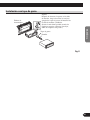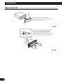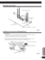
1
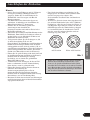
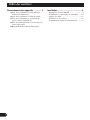
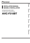
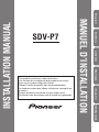
ESPAÑOL
DEUTSCH
FRANÇAIS
ITALIANO
NEDERLANDS
INSTALLATION MANUAL
ENGLISH
This product conforms to new cord colors.
Los colores de los cables de este producto se conforman con un nuevo código de colores.
Dieses Produkt entspricht den neuen kabelfarben.
Le code de couleur des câbles utilisé pour ce produit est
nouveau.
Questo prodotto è conforme ai nuovi codici colori.
De kleuren van de snoeren van dit toestel zijn gewijzigd.
MANUEL D’INSTALLATION
SDV-P7
Contents
Connecting the Units ................................ 2
When Connecting the Multi-Channel AV
Master Unit
- When Connecting the Head Unit
- When Connecting the Display with RCA
Input Jacks
- When Using a Display Connected Rear
Video Output
- Connecting the Power Cord
-
1
Installation .................................................. 9
Mode Switch Setting ........................................ 9
Installation with the rubber bush .................... 10
Removing the Unit .......................................... 11
Mounting with Brackets .................................. 12
Installing the Remote Sensor .......................... 12
Connecting the Units
Note:
OF
O
STAR
STAR
DEUTSCH
T
ACC position
F
T
OF
O
ESPAÑOL
ACC
N
F
ENGLISH
• To prevent incorrect connection, the input side of
the IP-BUS connector is blue, and the output side
is black. Connect the connectors of the same colors correctly.
• If this unit is installed in a vehicle that does not
have an ACC (accessory) position on the ignition
switch, the red lead of the unit should be connected to a terminal coupled with ignition switch
ON/OFF operations. If this is not done, the vehicle battery may be drained when you are away
from the vehicle for several hours. (Fig. 1)
N
No ACC position
Fig. 1
• Cords for this product and those for other products may be different colors even if they have
the same function. When connecting this product
to another product, refer to the supplied
Installation manuals of both products and connect cords that have the same function.
FRANÇAIS
• This unit is for vehicles with a 12-volt battery and
negative grounding. Before installing it in a recreational vehicle, truck, or bus, check the battery
voltage.
• To avoid shorts in the electrical system, be sure to
disconnect the ≠ battery cable before beginning
installation.
• Refer to the owner’s manual for details on connecting the power amp and other units, then make
connections correctly.
• Secure the wiring with cable clamps or adhesive
tape. To protect the wiring, wrap adhesive tape
around them where they lie against metal parts.
• Route and secure all wiring so it cannot touch any
moving parts, such as the gear shift, handbrake,
and seat rails. Do not route wiring in places that
get hot, such as near the heater outlet. If the insulation of the wiring melts or gets torn, there is a
danger of the wiring short-circuiting to the vehicle
body.
• Don’t pass the yellow lead through a hole into the
engine compartment to connect to the battery.
This will damage the lead insulation and cause a
very dangerous short.
• Do not shorten any leads. If you do, the protection
circuit may fail to work when it should.
• Never feed power to other equipment by cutting
the insulation of the power supply lead of the unit
and tapping into the lead. The current capacity of
the lead will be exceeded, causing overheating.
• When replacing fuse, be sure to use only fuse of
the rating prescribed on the fuse holder.
ITALIANO
NEDERLANDS
2
Connecting the Units
When Connecting the Multi-Channel AV Master Unit
Multi-Channel AV
Master Unit (e.g. AVM-P9000R)
(sold separately)
Green
Yellow
Blue
Blue
Optical cable (supplied with the
Multi-Channel AV Master Unit)
IP-BUS cable
(supplied with the TV tuner)
Black
FM MODULATOR
IP-BUS MAIN UNIT
IP-BUS AV MASTER
Blue
Hide-away TV Tuner
(e.g. GEX-P7000TVP)
(sold separately)
RCA cable
(sold separately)
Green
Red
20 pin cable
(supplied with the TV tuner)
3
Gray
ENGLISH
Yellow (front video output)
IP-BUS
STAND ALONE
This product
15 cm
Black
Yellow
ESPAÑOL
RCA cable (supplied)
Blue
Not used.
IP-BUS cable
(supplied with the MultiChannel AV Master Unit)
40 cm
6m
Blue
DEUTSCH
Blue
V.SEL cable
(supplied with the display)
Multi-CD player
(sold separately)
FRANÇAIS
Speaker Unit
(supplied with the
display)
Blue
ITALIANO
Black
AV system Display
(e.g. AVX-P7000CD)
(sold separately)
Green
IP-BUS cable
(supplied with the display)
NEDERLANDS
Gray
AV cable (supplied with the
Multi-Channel AV Master Unit)
Gray
20 pin cable
(supplied with the display)
Fig. 2
4
Connecting the Units
When Connecting the Head Unit
IP-BUS
STAND ALONE
This product
Head Unit
(sold separately)
Not used.
Blue
15 cm
Blue
40 cm
Blue
IP-BUS cable
(sold separately)
AV-BUS cable
(sold separately)
Red
IP-BUS cable
(supplied with the TV tuner)
AV system display
(e.g. AVX-7300)
(sold separately)
Black
FM MODULATOR
IP-BUS MAIN UNIT
IP-BUS AV MASTER
Hide-away TV Tuner
(e.g. GEX-P7000TVP)
(sold separately)
Green
Red
20 pin cable
(supplied with the display)
Fig. 3
5
When Connecting the Display with RCA Input Jacks
ENGLISH
White (audio output (Left))
IP-BUS
STAND ALONE
Red (audio output (Right))
ESPAÑOL
This product
Yellow (front
video output)
Remote sensor
(supplied)
DEUTSCH
RCA cable (supplied)
6m
FRANÇAIS
RCA cable (sold separately)
To video input
To audio inputs
ITALIANO
Display with RCA
input jacks
This product features a built-in
remote sensor. If it is installed in a
location where reception of the
remote control signal is not possible,
use the supplied remote sensor.
Connecting a rear display
NEDERLANDS
Instead of video output for viewing on a front display, you can connect for video output
enabling viewing on a rear display (for passengers in the rear of the car). If you decide to
use a rear display, be sure to follow the warnings on page 8.
Fig. 4
6
Connecting the Units
When Using a Display Connected Rear Video Output
This product’s rear video output is for connection of a display to enable passengers in the
rear seats to watch the DVD or Video CD.
WARNING
• NEVER install the display in a location that enables the Driver to watch the DVD or
Video CD while Driving.
White (audio output (Left))
IP-BUS
STAND ALONE
Red (audio output (Right))
This product
Yellow (rear
video output)
RCA cable (supplied)
RCA cable (sold separately)
To video input
To audio inputs
Display with RCA
input jacks
Fig. 5
7
Connecting the Power Cord
ENGLISH
This product comes with two kinds of power cord. Use the short cord when installing this
product in the dashboard, and the long cord when installing it on the floor.
Connection method
ESPAÑOL
1. Clamp the parking brake
switch power supply side
lead.
This Product
2. Clamp firmly with
needle-nosed pliers.
DEUTSCH
Note:
• The position of the parking brake switch depends
on the vehicle model. For details, consult the
vehicle Owner’s Manual or dealer.
FRANÇAIS
Light green
Used to detect the ON/OFF status of the parking brake.
This lead must be connected to the power supply side
of the parking brake switch.
Parking brake switch
Power supply side
Ground side
Red
To electric terminal controlled by ignition
switch (12 V DC) ON/OFF.
NEDERLANDS
Fuse holder
ITALIANO
Fuse resistor
Yellow
To terminal always supplied with power
regardless of ignition switch position.
Black (ground)
To vehicle (metal) body.
Fig. 6
8
Installation
Note:
• Before finally installing the unit, connect the
wiring temporarily, making sure it is all connected up properly, and the unit and the system work
properly.
• Use only the parts included with the unit to ensure
proper installation. The use of unauthorized parts
can cause malfunctions.
• Consult with your nearest dealer if installation
requires the drilling of holes or other modifications of the vehicle.
• Install the unit where it does not get in the driver’s way and cannot injure the passenger if there
is a sudden stop, like an emergency stop.
• The semiconductor laser will be damaged if it
overheats, so don’t install the unit anywhere hot
— for instance, near a heater outlet.
• If installation angle exceeds 30° from horizontal,
the unit might not give its optimum performance.
(Fig. 7)
• When mounting this unit, make sure none of the
leads are trapped between this unit and the surrounding metalwork or fittings.
• Do not mount this unit near the heater outlet,
where it would be affected by heat, or near the
doors, where rainwater might splash onto it.
• Before drilling any mounting holes always check
behind where you want to drill the holes. Do not
drill into the gas line, brake line, electrical wiring
or other important parts.
• If this unit is installed in the passenger compartment, anchor it securely so it does not break free
while the car is moving, and cause injury or an
accident.
• If this unit is installed under a front seat, make
sure it does not obstruct seat movement. Route all
leads and cords carefully around the sliding mechanism so they do not get caught or pinched in the
mechanism and cause a short circuit.
• Do not mount this unit on the spare tire board or
any other unstable place.
• Do not mount this unit anywhere that gets the sun
and so becomes hot, like on the dashboard or the
rear shelf.
• Mount this unit on a flat surface.
MODE Switch Setting
Fig. 7
Before installing, use a pen tip or other thin,
pointed instrument to set the MODE Switch to
the appropriate position for the component you
are using it with.
IP-BUS
9
STAND ALONE
Installation with the rubber bush
182
ESPAÑOL
53
ENGLISH
Dashboard
Holder
After inserting the holder into the dashboard, then select the appropriate tabs
according to the thickness of the dashboard material and bend them.
(Install as firmly as possible using the
top and bottom tabs. To secure, bend
the tabs 90 degrees.)
Rubber bush
Screw
DEUTSCH
Fig. 8
FRANÇAIS
ITALIANO
NEDERLANDS
10
Installation
Removing the Unit
Frame
Pull out to remove the frame.
(When reattaching the frame, point the
side with a groove downwards and
attach it.)
Fig. 9
7
Insert the supplied extraction keys
into the unit, as shown in the figure,
until they click into place. Keeping
the keys pressed against the sides of
the unit, pull the unit out.
Fig. 10
11
Mounting with Brackets
ENGLISH
Tapping screw (6 × 16 mm)
ESPAÑOL
Truss screw (5 × 8 mm)
DEUTSCH
Bracket
Car mat or chassis
Drill 4 to 4.5 mm diameter holes.
Fig. 11
FRANÇAIS
Installing the Remote Sensor
Precaution:
• Do not install on the dashboard where it may be subjected to direct sunlight. High temperatures
may result in damage to the unit.
• Install within the transmission range of the remote control signal.
ITALIANO
Stick the supplied double-sided tape to the back of the remote sensor, and attach it to the
center console.
Remote sensor
Double-sided tape
NEDERLANDS
Fig. 12
12
Contenido
Conexión de las unidades ........................ 2
Cuando conecte la Unidad Principal
Audiovisual Multicanal
- Cuando conecte la unidad principal
- Cuando conecte la presentación visual con
tomas de entrada RCA
- Cuando utilice un presentación visual
conectado a la salida de vídeo trasera
- Conexión del cable de alimentación
-
1
Instalación .................................................. 9
Ajuste del interruptor MODE ............................ 9
Instalación con tope de goma .......................... 10
Extracción de la unidad .................................. 11
Montaje con ménsulas .................................... 12
Instalación del sensor remoto .......................... 12
Conexión de las unidades
Nota:
OF
O
STAR
STAR
DEUTSCH
T
Posición ACC
F
T
OF
O
ESPAÑOL
ACC
N
F
ENGLISH
• Para evitar la conexión incorrecta, el lado de entrada del conector IP-BUS es azul, y el lado de
salida es negro. Conecte los conectores del mismo
color correctamente.
• Si se instala esta unidad en un vehículo que no
tiene una posición ACC (accesorio) en el interruptor de encendido, el conductor rojo de la unidad
deberá conectarse al terminal conectado con las
operaciones del interruptor de encendido
ON/OFF. Si no se hace esto, la batería del
vehículo podría drenarse cuando usted esté lejos
del vehículo por varias horas. (Fig. 1)
N
No en la posición ACC
Fig. 1
• Los cables para este producto y aquéllas para
otros productos pueden ser de colores diferentes
aun si tienen la misma función. Cuando se conecta este producto a otro, refiérase a los manuales
de instalación de ambos productos y conecte los
cables que tienen la misma función.
FRANÇAIS
• Esta unidad es para vehículos con batería de 12
voltios y con conexión a tierra. Antes de instalar
la unidad en un vehículo recreativo, camioneta, o
autobús, revise el voltaje de la batería.
• Para evitar cortocircuitos en el sistema eléctrico,
asegúrese de desconectar el cable de la batería ≠
antes de comenzar con la instalación.
• Consulte con el manual del usuario para los
detalles sobre la conexión de la alimentación de
amperios y de otras unidades, luego haga las
conexiones correctamente.
• Asegure el cableado con abrazaderas de cables o
con cinta adhesiva. Para proteger el cableado,
envuélvalo con cinta adhesiva donde éstos se
apoyan sobre las piezas de metal.
• Coloque y asegure todo el cableado de tal manera
que no toque las piezas en movimiento, tal como
la palanca de cambio de velocidades, el freno de
mano, y los pasamanos de los asientos. No
coloque el cableado en lugares que se calientan,
tal como cerca de la salida de un calefactor. Si el
material aislante del cableado se derritiera o se
gastara, habrá el peligro de un cortocircuito del
cableado a la carrocería del vehículo.
• No pase el conductor amarillo a través de un orificio en el compartimiento del motor para conectar
a la batería. Esto dañará el material aislante del
conductor y causará un cortocircuito peligroso.
• No acorte ningún conductor. Si lo hiciera, la protección del circuito podría fallar al funcionar
cuando debería.
• Nunca alimente energía a otros equipos cortando
el aislamiento del conductor de alimentación provista de la unidad y haciendo un empalme con el
conductor. La capacidad de corriente del conductor se excederá, causando el recalentamiento.
• Cuando reemplace algún fusible, asegúrese de utilizar solamente un fusible del ratio descrito en el
soporte de fusibles.
ITALIANO
NEDERLANDS
2
Conexión de las unidades
Cuando conecte la Unidad Principal Audiovisual Multicanal
Unidad Principal
Audiovisual Multicanal
(AVM-P9000R, por ejemplo)
(vendido separadamente)
Verde
Amarillo
Azul
Azul
Cable óptico
(suministrado con la Unidad Principal
Audiovisual Multicanal)
Cable IP-BUS (suministrado
con el sintonizador de TV)
Negro
FM MODULATOR
IP-BUS MAIN UNIT
IP-BUS AV MASTER
Azul
Sintonizador de TV
Hide-away (GEX-P7000TVP,
por ejemplo) (vendido
separadamente)
Cable RCA
(vendido separadamente)
Verde
Rojo
Cable de 20 patillas
(suministrado con el sintonizador de TV)
3
Gris
ENGLISH
Amarillo (FRONT VIDEO OUTPUT)
IP-BUS
STAND ALONE
Este producto
15 cm
Negro
ESPAÑOL
Cable RCA (suministrado) Amarillo
Azul
No se usa.
40 cm
6m
Cable IP-BUS
Azul
(suministrado con la Unidad
Principal Audiovisual Multicanal)
DEUTSCH
Azul
Cable V.SEL
(suministrado con la presentación visual)
Reproductor de
Multi-CD (vendido
separadamente)
FRANÇAIS
Unidad de altavoz
(suministrado con la
presentación visual)
Azul
ITALIANO
Negro
Pantalla de visualización
de sistema de AV
(AVX-P7000CD,
por ejemplo)
(vendido separadamente)
NEDERLANDS
Cable de AV
(suministrado con la Unidad Principal
Audiovisual Multicanal)
Verde
Cable IP-BUS (suministrado
con la presentación visual)
Gris
Gris
Cable de 20 patillas (suministrado
con la presentación visual)
Fig. 2
4
Conexión de las unidades
Cuando conecte la unidad principal
IP-BUS
STAND ALONE
Este producto
Unidad principal
(vendido separadamente)
No se usa.
Azul
15 cm
Azul
40 cm
Azul
Cable IP-BUS
(vendido separadamente)
Cable AV-BUS
(vendido
separadamente)
Rojo
Cable IP-BUS
(suministrado con el sintonizador de TV)
Pantalla de visualización de
sistema de AV
(AVX-7300, por ejemplo)
(vendido separadamente)
Negro
FM MODULATOR
IP-BUS MAIN UNIT
IP-BUS AV MASTER
Sintonizador de TV
Hide-away (GEX-P7000TVP)
(vendido separadamente)
Verde
Cable de 20 patillas
(suministrado con la
presentación visual)
Rojo
Fig. 3
5
Cuando conecte la presentación visual con tomas de entrada RCA
ENGLISH
Blanco (salida de áudio (canal izquierdo))
IP-BUS
STAND ALONE
Rojo (salida de áudio (canal derecho))
ESPAÑOL
Este producto
Amarillo
(FRONT VIDEO
OUTPUT)
Sensor remoto
(suministrado)
DEUTSCH
Cable RCA
(suministrado)
6m
FRANÇAIS
Cable RCA
(vendido separadamente)
A la entrada
de video
A las entradas
de audio
ITALIANO
Presentación visual
con tomas de entrada
RCA
Este producto se equipa con un
sensor remoto incorporado. Si se
instala el producto en un lugar en
donde la recepción de la señal del
control remoto no es posible, utilice
el sensor remoto suministrado.
Conexión de un presentación visual trasero
NEDERLANDS
En lugar de la salida de vídeo para ver las imágenes en un presentación visual delantero,
puede conectar la salida de vídeo para permitir la visualización en un presentación visual
trasero (para pasajeros en los asientos traseros del automóvil). Si decide utilizar un
presentación visual trasero, asegúrese de seguir las advertencias en la página 8.
Fig. 4
6
Conexión de las unidades
Cuando utilice un presentación visual conectado a la salida de vídeo trasera
La salida de vídeo trasera de este producto es para la conexión de un presentación visual
para permitir que los pasajeros en los asientos traseros puedan ver el DVD o Video CD.
ADVERTENCIA
• NUNCA instale el presentación visual en un lugar que permita el motorista ver el DVD
o Video CD mientras conduce el automóvil.
Blanco (salida de áudio (canal izquierdo))
IP-BUS
STAND ALONE
Rojo (salida de áudio (canal derecho))
Este producto
Amarillo
(REAR VIDEO
OUTPUT)
Cable RCA
(suministrado)
A la entrada
de video
Cable RCA
(vendido separadamente)
A las entradas
de audio
Presentación visual
con tomas de entrada
RCA
Fig. 5
7
Conexión del cable de alimentación
ENGLISH
Este producto viene con dos tipos de cable de alimentación. Utilice el cable corto al
instalar este producto en el tablero de instrumentos, y el cable largo al instalar en el piso.
Método de conexión
ESPAÑOL
1. Apriete el cable del lado
de alimentación del
interruptor del
freno de mano.
Este producto
2. Apriete firmemente
con alicates de
punta de aguja.
DEUTSCH
Nota:
• La posición del freno de estacionamiento depende
del modelo del vehículo. Para conocer detalles,
consulte el manual del propietario del vehículo o a
su concesionario.
Lado de alimentación
FRANÇAIS
Verde claro
Se utiliza para detectar el estado ON/OFF del freno de
mano. Este cable debe conectarse al lado de
alimentación del interruptor del freno de mano.
Interruptor del freno
de mano
Lado de masa
Rojo
Al terminal de energía eléctrica controlado
por el interruptor de encendido del
vehículo (12 V CC.) ON/OFF.
Amarillo
Al terminal con suministro constante de
electricidad, independientemente de la
posición del interruptor de encendido.
NEDERLANDS
Portafusible
ITALIANO
Resistencia de fusible
Negro (masa)
A la carrocería del veículo (parte metálica).
Fig. 6
8
Instalación
Nota:
• Antes de finalmente instalar la unidad, conecte el
cableado temporalmente y asegúrese de que todo
esté conectado correctamente y que la unidad y el
sistema funcionan debidamente.
• Utilice sólo las piezas que se incluyen con esta
unidad para asegurar la instalación adecuada. El
uso de piezas no autorizadas podría causar fallos
de funcionamiento.
• Consulte con su distribuidor si la instalación
requiere del taladro de orificios u otras modificaciones del vehículo.
• Instale la unidad donde no alcance el espacio del
conductor, y donde no pueda dañar a los pasajeros
si sucediera un paro repentino, como una detención de emergencia.
• El semiconductor láser se dañará si se sobrecalienta, por eso no instale la unidad en un lugar
caliente – por ejemplo, cerca de la salida de un
calefactor.
• Si el ángulo de la instalación excede los 30° del
lado horizontal, la unidad podría no brindar su
óptimo funcionamiento. (Fig. 7)
Fig. 7
• Cuando monte esta unidad, cerciórese que
ninguno de los cables queda aprisionado entre
esta unidad y accesorios o partes metálicas circundantes.
• No monte esta unidad cerca de la salida del calefactor, en donde podría ser afectado por el calor o
cerca de las puertas, en donde la lluvia podría
salpicar sobre la misma.
• Antes de taladrar cualquier orificio de montaje
siempre compruebe lo que hay detrás en donde
desea taladrar los orificios. No taladre en la línea
de combustible, cableado eléctrico u otras partes
importantes.
• Si esta unidad es instalada en el compartimiento
de pasajeros, fíjela seguramente de modo que no
se desprenda mientras el automóvil se encuentra
en movimiento, y pueda ocasionar lesiones o accidentes.
• Si esta unidad se instale bajo un asiento delantero,
cerciórese de que no obstruye el movimiento del
asiento. Pase todos los cables y conductores
cuidadosamente a través de los mecanismo
deslizantes, de modo que no queden aprisionados
o atrapados en el mecanismo y ocasionen un corto
circuito.
• No monte esta unidad en el tablero del neumático
de repuesto ni en cualquier lugar inestable.
• No monte esta unidad en donde quede sujeta a la
luz solar directa o en un lugar que deviene muy
caliente, como en el panel de instrumentos o bandeja trasera.
• Monte la unidad en una superficie plana.
Ajuste del interruptor MODE
Antes de instalar, utilice la punta de un bolígrafo u otro objeto puntiagudo para ajustar el
interruptor MODE a la posición apropiada
para el componente que utilice.
IP-BUS
9
STAND ALONE
Instalación con tope de goma
182
ESPAÑOL
53
ENGLISH
Tablero de
instrumentos
Soporte
Después de insertar el soporte en la tabla
de mandos, luego seleccione las orejetas
apropiadas según el grosor del material de
la tabla de mandos y dóblelos.
(Instale lo más firme posible usando las
lengüetas superior e inferior. Para fijar,
doble las lengüetas 90 grados.)
Tope de goma
Tornillo
DEUTSCH
Fig. 8
FRANÇAIS
ITALIANO
NEDERLANDS
10
Instalación
Extracción de la unidad
Marco
Tire hacia afuera para extraer el marco.
(Para la fijación del marco, apunte el lado
con ranura hacia abajo.)
Fig. 9
7
Inserte las herramientas de extracción
suministradas en la unidad, como se
indica en la figura, hasta que se
enganchen en su posición.
Tire de la unidad mientras mantiene las
herramientas presionadas contra los lados
de la unidad.
Fig. 10
11
Montaje con ménsulas
ENGLISH
Tornillo autoterrajante (6 × 16 mm)
ESPAÑOL
Tornillo de refuerzo
(5 × 8 mm)
DEUTSCH
Ménsula
Alfombra del automóvil o chasis
Taladre orificios de 4 a 4,5 mm de diámetro.
Fig. 11
FRANÇAIS
Instalación del sensor remoto
Precaución:
• No instale en el panel de instrumentos en donde quede sujeto a la luz solar directa. Las altas
temperaturas pueden averiar la unidad.
• Instale dentro de la gama de transmisión de la señal de control remoto.
ITALIANO
Fije la cinta de dos caras suministrada a la parte trasera del sensor remoto, y fíjela a la
consola central.
Sensor remoto
Cinta de dos caras
NEDERLANDS
Fig. 12
12
Inhalt
Anschließen der Einheiten ...................... 2
Bei Anschluß der Multikanal-AVHaupteinheit
- Bei Anschluß der Haupteinheit
- Bei Anschluß des Displays mit CinchEingangsbuchsen
- Bei Gebrauch eines am hinteren VideoAusgang angeschlossenen Displays
- Anschluß des Betriebsstromkabels
-
1
Einbauverfahren ........................................ 9
Einstellung des Betriebsartenschalters
(MODE) .................................................... 9
Einbau mit der Gummibuchse ........................ 10
Ausbau der Einheit .......................................... 11
Montage mit Halterungen ................................ 12
Installieren des Fernbedienungssensors .......... 12
Anschließen der Einheiten
Hinweis:
OF
O
STAR
STAR
DEUTSCH
T
ACC-Position
F
T
OF
O
ESPAÑOL
ACC
N
F
ENGLISH
• Um falsche Anschlüsse zu verhindern, ist die
Eingangsseite des IP-Bus-Steckverbinders blau
und die Ausgangsseite schwarz. Die
Steckverbinder derselben Farbe sind korrekt zu
verbinden.
• Wenn dieses Gerät in einem Auto eingebaut wird,
das auf dem Zündschalter keine ACC (Zubehör)Position hat, sollte die rote Leitung des Geräts an
eine Klemme angeschlossen werden, die mit der
ON/OFF-Operation des Zündschalters gekoppelt
ist. Andernfalls kann die Autobatterie entleert
werden, wenn Sie mehrere Stunden von dem
Fahrzeug weg sind. (Abb. 1)
N
Keine ACC-Position
Abb. 1
• Kabel dieses Produkts und die anderer Produkte
können unterschiedliche Farben haben, auch
wenn sie die gleichen Funktionen haben. Beim
Anschluß dieses Produkts an ein anderes Produkt
unter Bezugnahme auf die mit beiden Produkten
mitgelieferten Installationsanleitungen die Kabel
mit derselben Funktion verbinden.
FRANÇAIS
ITALIANO
• Dieses Gerät ist für Fahrzeuge mit 12-V-Batterie
und negativer Erdung (Minuspol an Masse)
ausgelegt. Prüfen Sie vor dem Einbau in ein
Wohnmobil, einen Lastwagen oder Bus die
Batteriespannung.
• Um Kurzschlüsse im elektrischen Systen zu
verhindern, ist unbedingt vor dem Einbau das
Minus-Batteriekabel ≠ abzutrennen.
• Nehmen Sie die Anschlüsse gemäß den
Anweisungen zum Anschluß des
Leistungsverstärkers und anderer Geräte in der
Bedienungsanleitung vor.
• Sichern Sie die Leitungen mit Kabelklemmen oder
Klebeband. Zum Schutz der Leitungen sollten sie
an den Stellen, wo sie Metallteile berühren, mit
Klebeband umwickelt werden.
• Verlegen und sichern Sie alle Leitungen so, daß
sie keine beweglichen Teile wie die
Gangschaltung, die Handbremse und Sitzschienen
berühren. Die Leitungen dürfen nicht an Stellen
entlanggeführt werden, die heiß werden, z.B. an
einer Heizungsauslaßöffnung. Wenn die Isolierung
einer Leitung schmilzt oder aufreißt, besteht die
Gefahr eines Kurzschlusses mit der Karosserie.
• Führen Sie die gelbe Leitung nicht durch ein Loch
in den Motorraum zum Anschluß an die Batterie.
Dadurch wird die Isolierung der Leitung
beschädigt, was zu einem sehr gefährlichen
Kurzschluß führen kann.
• Verkürzen Sie keine Leitungen. In diesem Fall
kann es vorkommen, daß die Schutzschaltung
nicht arbeitet, wenn sie gebraucht wird.
• Führen Sie niemals anderen Geräten Strom zu,
indem Sie die Isolierung der
Stromversorgungsleitung dieses Geräts
durchschneiden und davon Strom abzapfen.
Dadurch wird die Strombelastbarkeit der Leitung
überschritten, was zu Überhitzung führt.
• Benutzen Sie beim Auswechseln von Sicherungen
nur Sicherungen mit dem auf dem Sicherunshalter
angegebenen Nennwert.
NEDERLANDS
2
Anschließen der Einheiten
Bei Anschluß der Multikanal-AV-Haupteinheit
Multikanal-AVHaupteinheit
(z.B. AVM-P9000R)
(getrennt erhältlich)
Grün
Gelb
Blau
Blau
Lichtleiter Kabel (mit MultikanalAV-Haupteinheit mitgeliefert)
IP-BUS-Kabel
(mit dem TV-Tuner mitgeliefert)
Schwarz
FM MODULATOR
IP-BUS MAIN UNIT
IP-BUS AV MASTER
Blau
Hide-away-TV-Tuner
(z.B. GEX-P7000TVP)
(getrennt erhältlich)
RCA-Kabel
(getrennt erhältlich)
Grün
Rot
20-Pin-Kabel
(mit dem TV-Tuner mitgeliefert)
3
Grau
ENGLISH
Gelb (FRONT VIDEO OUTPUT)
IP-BUS
STAND ALONE
Dieses Produkt
15 cm
Schwarz
Gelb
ESPAÑOL
RCA-Kabel (mitgeliefert)
Blau
Nicht benutzt.
6m
IP-BUS-Kabel
(mit Multikanal-AVHaupteinheit mitgeliefert)
40 cm
Blau
DEUTSCH
Blau
V.SEL-Kabel
(mit Display mitgeliefert)
Multi-CD-Player
(getrennt erhältlich)
FRANÇAIS
Lautsprecher-Einheit
(mit Display mitgeliefert)
Blau
ITALIANO
Schwarz
AV-System-Display
(z.B. AVX-P7000CD)
(getrennt erhältlich)
Grün
IP-BUS-Kabel
(mit Display mitgeliefert)
NEDERLANDS
AV-Kabel
(mit Multikanal-AVHaupteinheit mitgeliefert)
Grau
Grau
20-Pin-Kabel
(mit Display mitgeliefert)
Abb. 2
4
Anschließen der Einheiten
Bei Anschluß der Haupteinheit
IP-BUS
STAND ALONE
Dieses Produkt
Haupteinheit
(getrennt erhältlich)
Nicht benutzt.
Blau
15 cm
Blau
40 cm
Blau
IP-BUS-Kabel
(getrennt erhältlich)
AV-BUS-Kabel
(getrennt erhältlich)
Rot
IP-BUS-Kabel
(mit dem TV-Tuner mitgeliefert)
AV-System-Display
(z.B. AVX-7300)
(getrennt erhältlich)
Schwarz
FM MODULATOR
IP-BUS MAIN UNIT
IP-BUS AV MASTER
Hide-away-TV-Tuner
(z.B. GEX-P7000TVP)
(getrennt erhältlich)
Grün
Rot
20-Pin-Kabel
(mit Display mitgeliefert)
Abb. 3
5
Bei Anschluß des Displays mit Cinch-Eingangsbuchsen
ENGLISH
Weiß (Audio-Ausgang (Links))
IP-BUS
STAND ALONE
Rot (Audio-Ausgang (Rechts))
ESPAÑOL
Dieses Produkt
Gelb
(FRONT VIDEO
OUTPUT)
Fernbedienungssensor
(mitgeliefert)
DEUTSCH
RCA-Kabel
(mitgeliefert)
6m
FRANÇAIS
RCA-Kabel
(getrennt erhältlich)
Zu Video-Eingang
Zu Audio-Eingängen
ITALIANO
Display mit RCAEingangsbuchsen
Dieses Produkt ist mit einem
eingebauten Fernbedienungssensor
ausgestattet. Bei Installation an einer
Stelle, an der Empfang des
Fernbedienungssignals nicht möglich
ist, verwenden Sie den mitgelieferten
Fernbedienungssensor.
Anschließen eines hinteren Displays
NEDERLANDS
Anstatt des Video-Ausgangs für Wiedergabe mit einem vorderen Display kann der
Anschluß für Video-Ausgang für Betrachtung auf einem hinteren Display (für Passagiere
auf dem Rücksitz) vorgenommen werden. Falls Sie sich für einen hinteren Display
entscheiden, sollten Sie unbedingt die Warnungen auf Seite 8.
Abb. 4
6
Anschließen der Einheiten
Bei Gebrauch eines am hinteren Video-Ausgang angeschlossenen Displays
Der hintere Video-Ausgang dieses Produkts ist zum Anschluß eines Displays vorgesehen,
damit Mitfahrer auf den Rücksitzen DVDs oder Video CDs sehen können.
WARNUNG
• Das Display darf AUF KEINEN FALL an einer Stelle installiert werden, an der es vom
Fahrer während der Fahrt eingesehen werden kann.
Weiß (Audio-Ausgang (Links))
IP-BUS
STAND ALONE
Rot (Audio-Ausgang (Rechts))
Dieses Produkt
Gelb
(REAR VIDEO
OUTPUT)
RCA-Kabel
(mitgeliefert)
Zu Video-Eingang
RCA-Kabel
(getrennt erhältlich)
Zu Audio-Eingängen
Display mit RCAEingangsbuchsen
Abb. 5
7
Anschluß des Betriebsstromkabels
ENGLISH
Mit diesem Produkt werden zwei verschiedene Stromversorgungskabel geliefert. Zur
Installation dieses Produkts in das Armaturenbrett ist das kurze Kabel zu verwenden. Zur
Montage auf dem Boden hingegen dient das lange Kabel.
Anschlußmethode
ESPAÑOL
1. Die Betriebsstromseite
des Parkbremsschalters
anklemmen.
Dieses Produkt
2. Fest mit einer
Nadelzange
einklemmen.
DEUTSCH
Hinweis:
• Die Position des Parkbremsschalters hängt vom
Fahrzeugmodell ab. Einzelheiten entnehmen Sie aus
der technischen Dokumentation des Fahrzeugs oder
erfragen sie beim Händler.
Stromversorgungsseite
FRANÇAIS
Hellgrün
Dieser Anschluß dient zur Erkennung des ON/OFF-Status
der Handbremse. Das Kabel ist an die Stromversorgungsseite
des Handbremsenschalters anzuschließen.
Handbremsenschalter
Masseseite
Rot
An eine Stromversorgung anschließen,
(12 V Gleichstrom), die mit dem Zündschloß
ein- und ausgeschaltet wird.
Gelb
An eine Stromversorgung anschließen,
die unabhängig vom Zündschloß immer
Strom führt.
Schwarz (Erdung)
An die Karosserie (Metallteil) anschließen.
NEDERLANDS
Sicherungshalter
ITALIANO
Sicherungswiderstand
Abb. 6
8
Einbauverfahren
Hinweis:
• Schließen Sie vor dem Einbau die Leitungen
vorübergehend an und stellen Sie sicher, das alles
richtig angeschlossen ist und das Gerät und das
System einwandfrei arbeiten.
• Um einwandfreien Einbau zu gewährleisten,
sollten nur die mit dem Gerät mitgelieferten Teile
verwendet werden. Bei Verwendung von NichtOriginalteilen kann es zu Funktionsstörungen
kommen.
• Wenden Sie sich an Ihren Fachhänlder, wenn zum
Einbau des Geräts Löcher gebohrt oder andere
Veränderungen an Ihrem Auto vorgenommen
werden müssen.
• Bauen Sie das Gerät an einer Stelle ein, wo es den
Fahrer nicht behindert und den Beifahrer bei
plötzlichem Bremsen nicht verletzen an.
• Der Halbleiterlaser wird bei Überhitzung
beschädigt, bauen Sie das Gerät daher nicht an
einer Stelle ein, wo es heiß wird, z.B. nahe einer
Heizungsauslaßöffnung.
• Wenn der Einbauwinkel mehr als 30º von der
Horizontalen abweicht, kann es sein, daß das
Gerät nicht optimal arbeitet. (Abb. 7)
Abb. 7
• Bei Montage des Geräts sicherstellen, daß keine
Leitung zwischen dem Gerät und umgebenden
Metallteilen oder Beschlägen eingeklemmt wird.
• Das Gerät nicht in der Nähe eines
Warmluftauslasses, wo es durch Wärme
beeinträchtigt werden könnte, oder in der Nähe
der Türen montieren, wo es bei Regen
Feuchtigkeit ausgesetzt sein könnte.
• Bevor irgendwelche Montagelöcher gebohrt
werden, stets nachkontrollieren, was sich hinter
der vorgesehenen Bohrstelle befindet. Darauf
achten, nicht in Kraftstoffleitung, Bremsleitung,
ein elektrisches Kabel oder andere wichtige Teile
zu bohren.
• Falls dieses Gerät im Beifahrerraum montiert
wird, muß es sicher verankert werden, so daß es
sich während der Fahrt nicht lösen und
Verletzungen bzw. einen Unfall verursachen
kann.
• Falls dieses Gerät unter einem Vordersitz
montiert wird, sicherstellen, daß der Sitz nach wie
vor voll verschoben werden kann. Alle Kabel
sorgfältig um den Verschiebemechanismus
verlegen, so daß sie sich nicht verfangen oder
eingeklemmt werden können, um Kurzschlüsse zu
vermeiden.
• Montieren Sie dieses Gerät nicht auf der
Reservereifenplatte oder einer anderen instabilen
Stelle.
• Montieren Sie dieses Gerät nicht an einer Stelle,
an der es direkter Sonnenbestrahlung ausgesetzt
ist und warm werden kann, wie z.B. auf dem
Armaturenbrett oder auf der hinteren Ablage.
• Montieren Sie dieses Gerät auf einer ebenen
Oberfläche.
Einstellung des Betriebsartenschalters (MODE)
Vor der Installation stellen Sie den
Betriebsartenschalter MODE mit der Spitze
eines Kugelschreibers oder einem anderen
dünnen, spitzen Gegenstand auf die richtige
Position für die Komponente ein, mit der das
Gerät betrieben werden soll.
IP-BUS
9
STAND ALONE
Einbau mit der Gummibuchse
182
ESPAÑOL
53
ENGLISH
Armaturenbrett
Halter
Den Halter in das Armaturenbrett einsetzen,
dann die der Dicke des Armaturenbretts
entsprechenden Zungen auswählen und
diese biegen.
(Mit Hilfe der Ansätze, oben und unten, so
fest wie möglich einsetzen. Zur Sicherung
werden die Ansätze 90 Grad gebogen.)
Gummibuchse
Schraube
DEUTSCH
Abb. 8
FRANÇAIS
ITALIANO
NEDERLANDS
10
Einbauverfahren
Ausbau der Einheit
Rahmen
Herausziehen, um den Rahmen
abzunehmen. (Beim Wiederanbringen des
Rahmens muß die Seite mit der Nut nach
unten weisen.)
Abb. 9
7
Die mitgelieferten Ausziehschlüssel wie
in der Abbildung gezeigt bis zur
Einrastposition in das Gerät einsetzen.
Die Schlüssel gegen die Seiten des
Geräts drücken und das Gerät
herausziehen.
Abb. 10
11
Montage mit Halterungen
ENGLISH
Schneidschraube (6 × 16 mm)
ESPAÑOL
Flachrundkopfschraube
(5 × 8 mm)
DEUTSCH
Halterung
Bodenmatte oder Fahrwerk
Löcher mit einem Durchmesser
von 4 bis 4,5 mm bohren.
Abb. 11
FRANÇAIS
Installieren des Fernbedienungssensors
Zur besonderen Beachtung:
• Meiden Sie eine Montage auf dem Armaturenbrett und anderen Stellen mit direkter
Sonnenbestrahlung. Hohe Temperaturen können zu einer Beschädigung führen.
• Nehmen Sie die Installation innerhalb des Übertragungsbereichs des Fernbedienungssignals vor.
ITALIANO
Haften Sie das mitgelieferte Doppelseiten-Klebeband an der Rückseite des
Fernbedienungssensors an, und bringen Sie diesen an der Mittelkonsole an.
Fernbedienungssensor
Doppelseiten-Klebeband
NEDERLANDS
Abb. 12
12
Table des matières
Raccordements des appareils ................ 2
Lors du raccordement à l’unité maîtresse
audiovisuel multicanaux
- Lors du raccordement à l’élément central
- Lors du raccordement à l’écran muni de
prises d’entrée Cinch (RCA)
- Lors de l’utilisation d’un écran raccordé à la
sortie vidéo arrière
- Branchement du cordon d’alimentation
-
1
Installation .................................................. 9
Réglage du sélecteur MODE ............................ 9
Installation avec une bague en caoutchouc .... 10
Dépose de l’unité ............................................ 11
Fixation avec les équerres .............................. 12
Installation du capteur de télécommande ........ 12
Raccordements des appareils
Remarque:
OF
O
STAR
STAR
DEUTSCH
T
Position ACC
F
T
OF
O
ESPAÑOL
ACC
N
F
ENGLISH
• Pour éviter une connexion incorrecte, le côté
entrée du connecteur IP-BUS est bleu et même
couleur correctement.
• Si cette unité est installée dans un véhicule dont le
contacteur d’allumage n’a pas de position ACC
(accessoire), le fil rouge de l’unité doit être connecté à une borne couplée aux opérations de
marche/arrêt du contacteur d’allumage. Sinon, la
batterie du véhicule peut se décharger lorsque le
véhicule n’est pas utilisé pendant plusieurs heures.
(Fig. 1)
N
Aucune position ACC
Fig. 1
• Les câbles de ce produit et ceux d’autres
produits peuvent fort bien ne pas être de la
même couleur bien que remplissant la même
fonction. Pour relier ce produit à un autre produit,
utilisez le manuel d’installation de chacun et
effectuez les raccordements en ne tenant compte
que de la fonction de chaque câble.
FRANÇAIS
ITALIANO
• Cet appareil est destiné aux véhicules avec une
batterie de 12 V, avec pôle négatif à la masse.
Avant de l’installer dans un véhicule de loisir, un
camion ou un car, vérifier la tension de la batterie.
• Afin d’éviter tout risque de court-circuit,
débrancher le câble de la borne négative ≠ de la
batterie avant de commencer la pose.
• Pour le raccordement des câbles de l’amplificateur
de puissance et des autres appareils, se reporter au
manuel de l’utilisateur et procéder comme il est
indiqué.
• Fixer les câbles au moyen de colliers ou de
morceaux de ruban adhésif. Pour protéger le
câblage, enrouler la bande adhésive autour des
câbles à l’endroit où ceux-ci sont placés contre les
parties métalliques.
• Acheminer et fixer tout le câblage de telle sorte
qu’il ne touche pas les pièces mobiles, comme le
levier de changement de vitesse, le frein à main et
les rails des sièges. Ne pas acheminer les câbles
dans des endroits qui peuvent devenir chauds,
comme près de la sortie de radiateur. Si l’isolation
des câbles fond ou est se déchire, il existe un danger de court-circuit des câbles avec la carrosserie
du véhicule.
• Ne pas faire passer le conducteur jaune dans le
compartiment moteur par un trou pour le connecter
avec la batterie. Cela pourrait endommager sa gaine
d’isolation et provoquer un grave court-circuit.
• Ne pas court-circuiter les conducteurs. Dans le cas
contraire, le circuit de protection risque de ne pas
fonctionner.
• Ne jamais alimenter un autre appareil par un
branchement sur le câble d’alimentation de celuici. Le courant qui circulerait dans ce conducteur
pourrait dépasser la capacité du conducteur et
entraîner une élévation anormale de température.
• Lors du remplacement du fusible, n’utiliser qu’un
fusible de même ampérage (il est indiqué sur le
porte-fusible).
NEDERLANDS
2
Raccordements des appareils
Lors du raccordement à l’usnité maîtresse audiovisuel multicanaux
Unité maîtresse audiovisuel
multicanaux
(par ex. AVM-P9000R)
(vendu séparément)
Vert
Jaune
Bleu
Bleu
Câble optique (fourni avec l’unité
maîtresse audiovisuel multicanaux)
Câble IP-BUS (fourni avec
le syntoniseur de télévision)
Noir
FM MODULATOR
IP-BUS MAIN UNIT
IP-BUS AV MASTER
Bleu
Syntoniseur de télévision
déporté
(par ex. GEX-P7000TVP)
(vendu séparément)
Câble à fiches Cinch (RCA)
(vendu séparément)
Vert
Rouge
Câble à 20 broches
(fourni avec le syntoniseur de télévision)
3
Gris
ENGLISH
Jaune (FRONT VIDEO OUTPUT)
IP-BUS
STAND ALONE
Cet appareil
15 cm
Noir
Câble IP-BUS
(fourni avec l’unité
maîtresse audiovisuel
multicanaux)
ESPAÑOL
Câble à fiches Cinch (RCA) Jaune
(fourni)
Bleu
Non utilisé.
40 cm
6m
Bleu
DEUTSCH
Bleu
Câble V.SEL
(fourni avec l’écran)
Lecteur de CD à
chargeur (vendu
séparément)
FRANÇAIS
Haut-parleur
(fourni avec l’écran)
Bleu
ITALIANO
Noir
Affichage pour système AV
(par ex. AVX-P7000CD)
(vendu séparément)
Vert
Câble IP-BUS (fourni avec
l’écran)
NEDERLANDS
Gris
Câble audio/vidéo (fourni avec l’unité
maîtresse audiovisuel multicanaux)
Gris
Câble à 20 broches
(fourni avec l’écran)
Fig. 2
4
Raccordements des appareils
Lors du raccordement à l’élément central
IP-BUS
STAND ALONE
Cet appareil
Élément central
(vendu séparément)
Non utilisé.
Bleu
15 cm
Bleu
40 cm
Bleu
Câble IP-BUS
(vendu séparément)
Câble AV-BUS
(vendu séparément)
Rouge
Câble IP-BUS
(fourni avec le
syntoniseur de télévision)
Affichage pour système AV
(par ex. AVX-7300)
(vendu séparément)
Noir
FM MODULATOR
IP-BUS MAIN UNIT
IP-BUS AV MASTER
Syntoniseur de télévision
déporté
(par ex. GEX-P7000TVP)
(vendu séparément)
Vert
Rouge
Câble à 20 broches
(fourni avec l’écran)
Fig. 3
5
Lors du raccordement à l’écran muni de prises d’entrée Cinch (RCA)
ENGLISH
Blanc (sortie audio (gauche))
IP-BUS
STAND ALONE
Rouge (sortie audio (droite))
ESPAÑOL
Cet appareil
Jaune
(FRONT VIDEO
OUTPUT)
Capteur de télécommande
(fourni)
DEUTSCH
Câble à fiches Cinch (RCA)
(fourni)
6m
FRANÇAIS
Câble à fiches Cinch (RCA)
(vendu séparément)
Vers l’entrée
vidéo
Vers les
entrées audio
ITALIANO
Écran muni de prises
d’entrée Cinch (RCA)
Cet appareil comprend un capteur
de télécommande. S’il est installé
dans un endroit où la réception des
signaux de télécommande n’est pas
possible, utilisez le capteur de
télécommande fourni.
Raccordement d’un écran arrière
NEDERLANDS
Au lieu de la sortie vidéo destinée à l’écran placé à l’avant, vous pouvez raccorder la sortie
vidéo permettant de regarder les images sur un écran placé à l’arrière (pour les passagers
assis sur les sièges arrière). Si vous décidez d’utiliser un écran arrière, veillez à respecter
les avertissements qui figurent sur la page 8.
Fig. 4
6
Raccordements des appareils
Lors de l’utilisation d’un écran raccordé à la sortie vidéo arrière
La sortie vidéo arrière de cet appareil est destinée à un écran placé de telle sorte que les
passagers arrière puissent regarder les images fournies par un DVD ou un Video CD.
AVERTISSEMENT
• Veillez à ce que l’écran NE SOIT PAS installé en un endroit tel que le conducteur
puisse observer les images fournies par le DVD ou le Video CD tout en conduisant.
Blanc (sortie audio (gauche))
IP-BUS
STAND ALONE
Rouge (sortie audio (droite))
Cet appareil
Jaune
(REAR VIDEO
OUTPUT)
Câble à fiches Cinch (RCA)
(fourni)
Vers l’entrée
vidéo
Câble à fiches Cinch (RCA)
(vendu séparément)
Vers les
entrées audio
Écran muni de prises
d’entrée Cinch (RCA)
Fig. 5
7
Branchement du cordon d’alimentation
ENGLISH
Cet appareil est livré avec deux sortes de cordon d’alimentation. Utilisez le cordon court si
vous installez cet appareil dans le tableau de bord et utilisez le cordon long si vous
l’installez sur le plancher.
Méthode de connexion
ESPAÑOL
1. Immobilisez le fil
d’alimentation du
contacteur de frein à
main.
Cet appareil
2. Serrez fermement avec
une pince à mâchoires
pointues.
DEUTSCH
Remarque:
• La position du contacteur de frein à main dépend
du modèle de véhicule. Pour les détails, consultez
le manuel de l’utilisateur du véhicule ou un
concessionnaire.
S’éclaire de couleur verte
Utilisé pour détecter l’état ON/OFF du frein à main.
Ce conducteur doit être raccordé sur l’alimentation
du contacteur de frein à main.
FRANÇAIS
Côté alimentation
Contacteur de
frein à main
Côté masse
Rouge
Vers une borne dont l’alimentation est commandée
par la clé de contact (12 V CC).
NEDERLANDS
Porte-fusible
ITALIANO
Résistance fusible
Jaune
Vers une borne alimentée en permanence
indépendamment de la clé de contact.
Noir (masse)
Fil de masse vers un élément en métal apparent
de la voiture.
Fig. 6
8
Installation
Remarque:
• Avant de finaliser l’installation de l’appareil, connecter temporairement le câblage en s’assurant
que tout est correctement connecté et que l’appareil et le système fonctionnement correctement.
• Pour obtenir une bonne installation, n’utiliser que
les pièces de l’appareil. L’utilisation de pièces
non prévues risque de causer un mauvais fonctionnement.
• Consulter le concessionnaire le plus proche si
l’installation nécessite le percement de trous ou
toute autre modification du véhicule.
• Installer l’appareil à un endroit où il ne gêne pas
le conducteur et où il ne peut pas blesser les passagers en cas d’arrêt brusque, comme pendant un
arrêt d’urgence.
• Le laser semiconducteur sera endommagé en cas
de réchauffement excessif. Dans ce cas ne pas
installer l’appareil dans un endroit présentant une
température élevée, tel que sortie de chauffage.
• L’angle de l’installation, ne doit pas dépasser 30°
par rapport à l’horizontale, faute de quoi l’unité
ne fournira pas ses performances optimales.
(Fig. 7)
Fig. 7
• Veillez à ce que les câbles ne puissent pas être
pincés entre l’appareil et les pièces métalliques
environnantes.
• N’installez pas cet appareil près d’une bouche de
chauffage car la chaleur dégagée peut l’endommager; pareillement, évitez la proximité des portières car il pourrait être éclaboussé par la pluie ou
les intempéries.
• Avant d’effectuer un perçage requis par l’installation de l’appareil, assurez-vous que vous pouvez
le faire sans danger pour les câbles, canalisations,
flexibles, etc., qui sont placés derrière le panneau
que vous devez percer.
• Si vous installez l’appareil dans l’habitacle,
veillez à ce qu’il soit bien ancré de manière qu’il
ne puisse pas provoquer une blessure ou un accident en raison du déplacement du véhicule sur la
route.
• Si vous choisissez d’installer l’appareil sous un
siège avant, veillez à ce qu’il ne gêne pas la
manoeuvre du siège. Faites cheminer les câbles et
les conducteurs de telle manière qu’ils ne puissent
pas gêner le réglage du siège ni être endommagés
par son déplacement, ce qui pourrait provoquer un
court-circuit.
• Ne fixez pas l’appareil sur la planchette de la roue
de secours, ni sur aucune autre surface amovible.
• Ne fixez pas l’appareil en un endroit exposé au
soleil et qui peut devenir chaud, comme par
exemple, le tableau de bord ou la lunette arrière.
• Fixez l’appareil sur une surface plane.
Réglage du sélecteur MODE
Avant l’installation, utilisez la pointe d’un
stylo à bille ou tout autre instrument pointu et
fin pour placer le sélecteur MODE sur la position appropriée compte tenu de l’appareil que
vous utilisez conjointement.
IP-BUS
9
STAND ALONE
Installation avec une bague en caoutchouc
182
ESPAÑOL
53
ENGLISH
Tableau de bord
Support
Après avoir introduit le support dans le tableau de
bord, sélectíonnez les languettes appropriées en
fonction de l’épaisseur du matériau du tableau de
bord et courbez-les.
(Assurez le maintien aussi solidement que possible
en utilisant les languettes inférieures et supérieures.
Cela fait, courbez les languettes de 90 degrés.)
Bague en caoutchouc
Vis
DEUTSCH
Fig. 8
FRANÇAIS
ITALIANO
NEDERLANDS
10
Installation
Dépose de l’unité
Cadre
Tirez pour enlever le cadre. (Pour
remettre le cadre en place, dirigez le côté
avec la rainure vers le bas.)
Fig. 9
7
Insérer les clés d’extraction fournis dans
l’unité, comme indiqué dans la figure,
jusqu’à ce qu’elles s’enclenchent en
position. En maintenant ces clés pressées
contre les côtés de l’unité, retirer l’unité.
Fig. 10
11
Fixation avec les équerres
ENGLISH
Vis autotaraudeuse (6 × 16 mm)
ESPAÑOL
Vis à tête bombée (5 × 8 mm)
DEUTSCH
Equerre
Moquette ou châssis du véhicule
Percez des trous de 4 à 4,5 mm
de diamètre.
Fig. 11
FRANÇAIS
Installation du capteur de télécommande
Précaution:
• N’installez pas le capteur sur le tableau de bord où il peut être exposé à la lumière directe du soleil.
Les températures élevées peuvent endommager l’appareil.
• Installez le capteur dans la plage de transmission du signal de télécommande.
ITALIANO
Posez le ruban adhésif double-face à l’arrière du capteur de télécommande et fixez-le sur la
console centrale.
Capteur de télécommande
Ruban adhésif double-face
NEDERLANDS
Fig. 12
12
Indice
Collegamento delle unità ........................ 2
Per il collegamento dell’apparecchio
audio/video centralizzato multicanali
- Per il collegamento dell’unità di testa
- Quando si collega lo schermo con prese di
ingresso tipo RCA
- Uso di un schermo collegato all’uscita
video posteriore
- Collegamento del cavo di alimentazione
-
1
Installazione .............................................. 9
Impostazione della commutazione MODI ........ 9
Installazione con la boccola in gomma .......... 10
Rimozione dell’ unità ...................................... 11
Per mezzo delle staffe .................................... 12
Installazione del sensore per i segnali del
telecomando ............................................ 12
Collegamento delle unità
Nota:
OF
OF
F
O
STAR
STAR
T
O
ESPAÑOL
ACC
N
F
ENGLISH
• Per evitare un collegamento sbagliato, il lato di
ingresso del connettore IP-BUS è blu, mentre il
lato di uscita è nero. Collegare i connettori dello
stesso colore correttamente.
• Se questo apparecchio viene installato in un veicolo che non possiede una posizione ACC (accessoria) sull’interruttore di accensione, il cavo rosso
dell’apparecchio deve essere collegato ad un terminale accoppiato con le operazioni di accensione/
spegnimento dell’interruttore di accensione. Se ciò
non viene fatto, la batteria del veicolo può scaricarsi quando si lascia il veicolo per alcune ore (Fig. 1).
N
DEUTSCH
T
Posizione ACC presente Posizione ACC assente
Fig. 1
• I cavi per questo apparecchio e quelli per altri
apparecchi possono avere colori diversi, pur
svolgendo la stessa funzione. Per il collegamento
di questo apparecchio ad un’altro, vedere i
manuali di installazione di entrambi gli
apparecchi, e provvedere al collegamento dei
cavi aventi la stessa funzione.
FRANÇAIS
ITALIANO
• Questo apparecchio è per veicoli con una batteria
da 12 volt e una messa a massa negativa. Prima di
installarlo in un veicolo sportivo, in un autocarro o
in un autobus, controllare la tensione della batteria.
• Per evitare cortocircuiti nell’impianto elettrico,
accertarsi di scollegare il cavo della batteria ≠
prima di iniziare l’installazione.
• Fare riferimento al manuale di istruzioni per i dettagli sul collegamento dell’amplificatore di potenza
e di altri apparecchi, quindi eseguire i collegamenti
correttamente.
• Fissare i fili con dei fermacavi o del nastro adesivo.
Per proteggere i fili, avvolgervi attorno del nastro
adesivo nei punti in cui essi sono a contatto con
parti metalliche.
• Disporre e fissare tutti i fili in modo tale che essi
non tocchino alcuna parte in movimento, come
l’asta del cambio, il freno a mano e le guide dei
sedili. Non disporre i fili in luoghi esposti al calore,
come nei pressi della bocca di efflusso dell’impianto di riscaldamento. Se la guaina isolante dei fili
si fonde o si lacera, c’è il pericolo che i fili possano
provocare cortocircuiti alla carrozzeria del veicolo.
• Non far passare il cavo giallo attraverso un foro per
inserirlo nel vano motore per collegare la batteria.
Questo danneggia la guaina isolante del cavo e può
causare un cortocircuito molto pericoloso.
• Non accorciare i cavi. Se si accorciano i cavi, il circuito di protezione potrebbe non funzionare quando invece dovrebe.
• Non fornire mai alimentazione ad un altro apparecchio tagliando la guaina isolante del cavo di alimentazione dell’apparecchio e collegando il cavo.
La capacità di corrente del cavo sarà superata causando surriscaldamento.
• Quando si sostituisce il fusibile, accertarsi di usare
soltanto un fusibile dai limiti di impiego indicati
sul portafusibili.
NEDERLANDS
2
Collegamento delle unità
Per il collegamento dell’apparecchio audio/video centralizzato multicanali
Apparecchio audio/video
centralizzato multicanali
(ad esempio, AVM-P9000R)
(venduto a parte)
Verde
Giallo
Blu
Blu
Cavo ottico (fornito con l’apparecchio
audio/video centralizzato multicanali)
Cavo IP-BUS
(fornito con il sintonizzatore TV)
Nero
FM MODULATOR
IP-BUS MAIN UNIT
IP-BUS AV MASTER
Blu
Sintonizzatore TV estraibile
(ad esempio, GEX-P7000TVP
(venduto a parte)
Cavo RCA
(venduto a parte)
Verde
Rosso
Cavo a 20 pin
(fornito con il sintonizzatore TV)
3
Grigio
ENGLISH
Giallo (FRONT VIDEO OUTPUT)
IP-BUS
STAND ALONE
Questo produtto
15 cm
Nero
Giallo
ESPAÑOL
Cavo RCA (fornito)
Blu
Non usato.
Cavo IP-BUS
(fornito con l’apparecchio 6 m
audio/video centralizzato
multicanali)
40 cm
Blu
DEUTSCH
Blu
Cavo V.SEL
(fornito insieme allo schermo)
Lettore multi-CD
(venduto a parte)
FRANÇAIS
Altoparlante
(fornito insieme allo schermo)
Blu
ITALIANO
Nero
Display del sistema AV
(ad esempio, AVX-P7000CD)
(venduto a parte)
Verde
Cavo IP-BUS
(fornito insieme allo schermo)
NEDERLANDS
Grigio
Cavo AV (fornito con l’apparecchio
audio/video centralizzato multicanali)
Grigio
Cavo a 20 pin
(fornito insieme allo schermo)
Fig. 2
4
Collegamento delle unità
Per il collegamento dell’unità di testa
IP-BUS
STAND ALONE
Questo produtto
Unità di testa
(venduto a parte)
Non usato.
Blu
15 cm
Blu
40 cm
Blu
Cavo IP-BUS
(venduto a parte)
Cavo AV-BUS
(venduto a parte)
Rosso
Cavo IP-BUS
(fornito con il sintonizzatore TV)
Display del sistema AV
(ad esempio, AVX-7300)
(venduto a parte)
Nero
FM MODULATOR
IP-BUS MAIN UNIT
IP-BUS AV MASTER
Sintonizzatore TV estraibile
(ad esempio, GEX-P7000TVP)
(venduto a parte)
Verde
Rosso
Cavo a 20 pin
(fornito insieme allo schermo)
Fig. 3
5
Quando si collega lo schermo con prese di ingresso tipo RCA
ENGLISH
Bianco (uscita audio (sinistra))
IP-BUS
STAND ALONE
Rosso (uscita audio (destra))
ESPAÑOL
Questo produtto
Giallo
(FRONT VIDEO
OUTPUT)
Sensore per i segnali
del telecomando
(fornito)
DEUTSCH
Cavo RCA (fornito)
6m
FRANÇAIS
Cavo RCA (venduto a parte)
All’ingresso video
Agli ingressi audio
ITALIANO
Schermo con prese di
ingresso di tipo RCA
Questo prodotto è dotato di un
sensore remoto incorporato. Se viene
installato in un luogo dove non è
possibile ricevere il segnale del
telecomando, utilizzare il sensore
remoto in dotazione.
Collegamento di un display posteriore
NEDERLANDS
Invece di collegarsi ad un’uscita video, per la visione su un display anteriore, è possibile
collegarsi ad un’uscita video che permette la visione su un display posteriore (per i passeggeri seduti sui sedili posteriori dell’auto). Nel caso si decida di usare un display posteriore,
rispettare rigorosamente gli avvertimenti elencati nella pagina 8.
Fig. 4
6
Collegamento delle unità
Uso di un schermo collegato all’uscita video posteriore
L’uscita video posteriore di quest’unità è prevista per il collegamento di un schermo che
permette ai passeggeri seduti sui sedili posteriori dell’auto di vedere un DVD o un CD
video.
AVVERTENZA
• NON installare MAI il schermo in modo che il conducente possa vedere il DVD o il CD
video riprodotto mentre guida.
Bianco (uscita audio (sinistra))
IP-BUS
STAND ALONE
Rosso (uscita audio (destra))
Questo produtto
Giallo
(REAR VIDEO
OUTPUT)
Cavo RCA (fornito)
Cavo RCA (venduto a parte)
All’ingresso video
Agli ingressi audio
Schermo con prese di
ingresso di tipo RCA
Fig. 5
7
Collegamento del cavo di alimentazione
ENGLISH
Questo prodotto è fornito di due tipi di cavi di alimentazione. Usare il cavo corto quando
si installa questo prodotto nel cruscotto e il cavo lungo quando lo si installa sul fondo
scocca.
Metodo di collegamento
ESPAÑOL
1. Fissare il cavo del lato
alimentazione
dell’interruttore freno
a mano.
Questo produtto
DEUTSCH
2. Fissare
saldamente con
pinze a punta.
Nota:
• La posizione dell’interruttore freno a mano dipende
dal modello di veicolo. Per dettagli consultare il
manuale del veicolo o il concessionario.
Lato alimentazione
FRANÇAIS
Luce verde
Usato per individuare lo stato attivato (ON)/disattivato (OFF)
del freno a mano. Questo cavo deve essere collegato al lato
alimentazione dell’interruttore freno a mano.
Interruttore freno
a mano
Lato massa
Rosso
Collegare alla chiave d’avviamento ON/OFF
(12 V C.C.).
NEDERLANDS
Portafusibili
ITALIANO
Resistenza fusibile
Giallo
Al terminale constantemente alimentato, qualunque
sia la posizione della chiave d’accensione.
Nero (massa)
Al telaio (parte metallica) dell’automobile.
Fig. 6
8
Installazione
Nota:
• Prima di installare definitivamente l’apparecchio,
collegare i fili temporaneamente e accertarsi che
tutti i collegamenti siano corretti e che
l’apparecchio e il sistema funzionino
correttamente.
• Per un’installazione appropriata, usare soltanto i
pezzi in dotazione all’apparecchio. L’uso di pezzi
non autorizzati può causare problemi di
funzionamento.
• Rivolgersi al più vicino rivenditore se
l’installazione richiede la trapanatura di fori o
altre modifiche del veicolo.
• Installare l’apparecchio in un punto in cui esso
non intralci le manovre del conducente e in cui
non possa provocare lesioni ai passeggeri nel caso
dell’arresto improvviso del veicolo, come nel caso
di una frenata d’emergenza.
• Il laser a semiconduttore subisce danni se si
surriscalda; pertanto, non installare l’apparecchio
in luoghi esposti al calore, come per esempio nei
pressi della bocca di efflusso dell’impianto di
riscaldamento.
• Se l’angolo di installazione supera i 30° rispetto
alla posizione orizzontale, l’apparecchio potrebbe
non fornire prestazioni ottimali. (Fig. 7)
Fig. 7
• Nel corso dell’installazione verificare che i cavi
non vengano a trovarsi strizzati fra l’apparecchio
stesso e le montature ed altri infissi di metallo
circostanti.
• Non installare l’apparecchio nelle vicinanze della
bocca del riscaldamento, dove potrebbe subire
l’influenza del flusso di aria calda, o nelle
vicinanze delle portiere, dove potrebbe trovarsi
esposto alla pioggia.
• Prima di aprire un foro, verificare sempre il lato
opposto del pannello dove si intende effettuare la
perforazione. Non aprire fori sulle linee dei tubi
del carburante o dei freni, sui cablaggi elettrici, e
su altre parti importanti per il funzionamento del
veicolo.
• Se l’apparecchio viene montato all’interno
dell’abitacolo della vettura, ancorarlo saldamente,
in modo che non abbia a staccarsi mentre la
vettura è in movimento, causando possibili lesioni
agli occupanti, o incidenti stradali.
• Se l’apparecchio viene installato sotto uno dei
sedili anteriori, verificare che la posizione non
blocchi il movimento del sedile stesso. Istradare
tutti i cavi con cura all’intorno del meccanismo di
scorrimento, in modo che non vengano a trovarsi
presi nei meccanismi, con conseguenti possibili
corti circuiti.
• Non montare quest’unità sul pannello della ruota
di scorta né su qualsiasi altra superficie instabile.
• Non montare quest’unità in punti esposti alla luce
solare che la riscaldi, quali la plancia anteriore o
la cappelliera posteriore.
• Montare l’unità su una superficie piana.
Impostazione della commutazione MODI
Usare la punta di una penna o un altro
strumento fine ed appuntito per impostare il
commutatore dei MODI sulla posizione
appropriata per il componente usato, prima di
installarlo.
IP-BUS
9
STAND ALONE
Installazione con la boccola in gomma
182
ESPAÑOL
53
ENGLISH
Cruscotto
Supporto
Dopo aver inserito il supporto nel cruscotto,
selezionare le linguette appropriate a seconda
dello spessore del materiale del cruscotto e
piegarle.
(Installare quanto più saldamente possibile
servendosi delle linguette superiore e inferiore.
Per fissare, piegare le linguette a 90 gradi.)
Boccola di gomma
Vite
DEUTSCH
Fig. 8
FRANÇAIS
ITALIANO
NEDERLANDS
10
Installazione
Rimozione dell’ unità
Cornice
Tirare verso l’esterno per staccare la
cornice. (Per riattaccare la cornice,
applicarla puntando il lato con la
scanalatura verso il basso.)
Fig. 9
7
Inserire le chiavette di estrazione in
dotazione nell’apparecchio, come
mostrato nella figura, finché non
scattano in posizione. Tenendo le
chiavette premute contro i lati
dell’apparecchio, estrarre l’apparecchio.
Fig. 10
11
Per mezzo delle staffe
ENGLISH
Vite autofilettante (6 × 16 mm)
ESPAÑOL
Vite di sostegno (5 × 8 mm)
DEUTSCH
Staffa
Tappetino dell’auto
o chassis
Fori di diametro compreso fra
4 e 4,5 mm.
Fig. 11
FRANÇAIS
Installazione del sensore per i segnali del telecomando
Precauzione:
• Non installarlo sulla plancia anteriore dove può essere esposto alla luce diretta del sole. Le alte temperature possono danneggiare l’unità.
• Installarlo entro la fascia di trasmissione del segnale emesso dal telecomando.
ITALIANO
Applicare il nastro biadesivo fornito sulla parte posteriore del sensore di telecomando ed
attaccarlo sulla console centrale.
Sensore per i
segnali del telecomando
Nastro biadesivo
NEDERLANDS
Fig. 12
12
Inhoud
Aansluiten van de apparatuur ................ 2
Aansluiten op een multikanaals AV
hoofdtoestel
- Aansluiten van een hoofdtoestel
- Bij aansluiting van het display met RCA
ingangsaansluitingen
- Bij gebruik van een op de achter-video
uitgangsaansluitingen aangesloten display
- Aansluiten van het stroomsnoer
-
1
Installeren .................................................. 9
Instelling van de MODE functieschakelaar ...... 9
Installatie met de rubber mof .......................... 10
Verwijderen van het apparaat .......................... 11
Bevestigen met beugels .................................. 12
Installeren van de sensor
afstandsbediening .................................... 12
Aansluiten van de apparatuur
Opmerking:
OF
O
STAR
STAR
DEUTSCH
T
ACC stand
F
T
OF
O
ESPAÑOL
ACC
N
F
ENGLISH
• Om vergissingen te voorkomen is de ingangskant
van de IP-BUS aansluiting blauw uitgevoerd en de
uitgangskant zwart. Let op dat u bij het aansluiten
deze kleurcode volgt.
• Bij inbouw van dit apparaat in een auto waarvan
het contactslot geen “ACC” stand heeft, dient u de
rode stroomdraad van dit apparaat aan te sluiten
op een aansluitpunt waarvan de stroom wordt inen
uitgeschakeld door ON/OFF zetten van het
contactsleuteltje. Als u deze stroomdraad aansluit
op een punt dat altijd stroom krijgt, kan de accu
leegraken als u de auto enkele uren ongebruikt
laat. (Afb. 1)
N
Geen ACC stand
Afb. 1
• Snoeren voor dit product en overeenkomende
snoeren voor andere producten hebbern mogelijk
verschillende kleuren ookal is de functie van de
snoeren hetzelfde. Zie voor het verbinden van dit
product met een ander product daarom de
installatichandleiding van beide producten en
verbind de snoeren met dezelfde functie met
elkaar.
FRANÇAIS
ITALIANO
• Dit apparaat is bestemd voor inbouw in auto’s
met een negatief geaarde 12-volts accu. Alvorens
u het installeert in een auto, bus, vrachtwagen of
ander voer- of vaartuig, dient u eerst te
controleren of de accuspanning de juiste is.
• Om kortsluiting te vermijden, dient u vooral voor
het installeren de negatieve ≠ accukabel los te
maken.
• Zie voor het aansluiten van de eindversterker en
andere apparatuur de gebruiksaanwijzing en volg
de aanwijzingen nauwgezet op.
• Houd de bedrading op zijn plaats met
kabelklemmen of met isolatieband. Wikkel ter
bescherming ook isolatieband om de bedrading
waar deze de metalen oppervlakken van de auto
raakt.
• Leid de bedrading altijd zo dat deze niet in
aanraking kan komen met bewegende onderdelen
zoals de versnellingspook, de handrem en de
geleiderails van de stoelen. Zet de bedrading
stevig vast en vermijd ook plaatsen die warm
worden, zoals bij een uitblaasopening van de
autoverwarming. Als de isolatie smelt of door
beweging doorslijt, zou er kortsluiting kunnen
onstaan.
• Leid de gele draad niet door het brandschot naar
de motorruimte voor aansluiting op de accu.
Hierbij is de kans groot op beschadiging van de
isolatie en zeer gevaarlijke kortsluiting.
• Maak de bedrading niet korter. Bij inkorten van
de bedrading kan het beveiligingscircuit niet in
werking treden wanneer dat nodig is.
• Tap geen stroom af van de bedrading door een
stukje isolatie te verwijderen en een andere draad
aan de kerndraad te verbinden. Hierdoor kan de
maximale stroomcapaciteit van de draad
overschreden worden, met als gevolg
oververhitting.
• Vervang een doorgebrande zekering altijd alleen
door een nieuwe zekering van hetzelfde type,
zoals aangegeven op de zekeringhouder.
NEDERLANDS
2
Aansluiten van de apparatuur
Aansluiten op een multikanaals AV hoofdtoestel
Multikanaals AV
hoofdtoestel
(bijv. AVM-P9000R)
(los verkrijgbaar)
Groen
Geel
Blauw
Blauw
Optische kabel (meegeleverd met
het multikanaals AV hoofdtoestel)
IP-BUS-kabel
(meegeleverd met de TV tuner)
Zwart
FM MODULATOR
IP-BUS MAIN UNIT
IP-BUS AV MASTER
Blauw
Verborgen TV tuner
(bijv. GEX-P7000TVP)
(los verkrijgbaar)
RCA-kabel
(los verkrijgbaar)
Groen
Rood
20-pens kabel
(meegeleverd met de TV tuner)
3
Grijs
ENGLISH
Geel (FRONT VIDEO OUTPUT)
IP-BUS
STAND ALONE
Dit toestel
15 cm
Zwart
ESPAÑOL
RCA-kabel (meegeleverd)
Geel
Blauw
Niet gebruikt.
40 cm
6m
IP-BUS-kabel
Blauw
(meegeleverd met het
multikanaals AV hoofdtoestel)
DEUTSCH
Blauw
V.SEL-kabel
(meegeleverd met het display)
Multi-CD-wisselaar
(los verkrijgbaar)
FRANÇAIS
Luidspreker-eenheid
(meegeleverd met
het display)
Blauw
ITALIANO
Zwart
AV systeem-display
(bijv. AVX-P7000CD)
(los verkrijgbaar)
Groen
IP-BUS-kabel
(meegeleverd met het display)
NEDERLANDS
Grijs
AV kabel (meegeleverd met het
multikanaals AV hoofdtoestel)
Grijs
20-pens kabel
(meegeleverd met het display)
Afb. 2
4
Aansluiten van de apparatuur
Aansluiten van een hoofdtoestel
IP-BUS
STAND ALONE
Dit toestel
Hoofdtoestel
(los verkrijgbaar)
Niet gebruikt.
Blauw
15 cm
Blauw
40 cm
Blauw
IP-BUS-kabel
(los verkrijgbaar)
AV-BUS-kabel
(los verkrijgbaar)
Rood
IP-BUS-kabel
(meegeleverd met de TV tuner)
AV systeem-display
(bijv. AVX-7300)
(los verkrijgbaar)
Zwart
FM MODULATOR
IP-BUS MAIN UNIT
IP-BUS AV MASTER
Verborgen TV tuner
(bijv. GEX-P7000TVP)
(los verkrijgbaar)
Groen
Rood
20-pens kabel
(meegeleverd met het display)
Afb. 3
5
Bij aansluiting van het display met RCA ingangsaansluitingen
ENGLISH
Wit (audio uitgang (Links))
IP-BUS
STAND ALONE
Rood (audio uitgang (Rechts))
ESPAÑOL
Dit toestel
Geel
(FRONT VIDEO
OUTPUT)
Sensor afstandsbediening
(meegeleverd)
DEUTSCH
RCA-kabel
(meegeleverd)
6m
FRANÇAIS
RCA-kabel
(los verkrijgbaar)
Naar de video
ingangsaansluiting
Naar de audio
ingangsaansluitingen
ITALIANO
Display met RCA (tulp)
ingangsaansluitingen
Dit product is uitgerust met een
ingebouwde sensor voor de
afstandsbediening. Als u dit
product installeert op een plek
waar het signaal van de
afstandsbediening niet kan worden
ontvangen, dient u de
meegeleverde sensor voor de
afstandsbediening te gebruiken.
Aansluiten van een achter-display
NEDERLANDS
U kunt in plaats van een voor-display, de aansluitingen maken voor een videosignaal naar
een achter-display (voor passagiers achterin de auto). Als u besluit een achter-display te
gebruiken, moet u de waarschuwingen op bladzijde 8 in acht nemen.
Afb. 4
6
Aansluiten van de apparatuur
Bij gebruik van een op de achter-video uitgangsaansluitingen aangesloten display
De achter-video uitgangsaansluitingen van dit product zijn bedoeld om een display op aan
te sluiten waarop passagiers op de achterbank naar DVD of Video CD kunnen kijken.
WAARSCHUWING
• Installeer het display NOOIT op een plek waar de bestuurder de DVD of Video CD kan
bekijken terwijl hij of zij aan het rijden is.
Wit (audio uitgang (Links))
IP-BUS
STAND ALONE
Rood (audio uitgang (Rechts))
Dit toestel
Geel
(REAR VIDEO
OUTPUT)
RCA-kabel
(meegeleverd)
RCA-kabel
(los verkrijgbaar)
Naar de video
ingangsaansluiting
Naar de audio
ingangsaansluitingen
Display met RCA (tulp)
ingangsaansluitingen
Afb. 5
7
Aansluiten van het stroomsnoer
ENGLISH
Dit product is voorzien van twee stroomsnoeren. Gebruik het korte snoer wanneer u dit
product in het dashboard monteert en het lange snoer wanneer u het op de vloer monteert.
Aansluitmethode
ESPAÑOL
1. Klem de stroomdraad van
de handremschakelaar in
de stekker vast.
Dit toestel
2. Maak de stekkerhelften
met een kabeltang dicht.
DEUTSCH
Opmerking:
• De plaats waar de handremschakelaar zich bevindt,
hangt af van het automodel. Zie het instructieboekje
van de auto of vraag uw autodealer.
Stroomdraad
FRANÇAIS
Licht groen
Via deze draad wordt de stand van de handrem
(aangetrokken/ontspannen) aan het autonavigatiesysteem
doorgegeven. De draad moet verbonden worden met de
stroomaansluiting van de handremschakelaar.
Handremschakelaar
Massadraad
Rood
Naar de door het contact (12 V gelijkstroom)
(ON/OFF) geregelde elektrische aansluiting.
NEDERLANDS
Zekeringhouder
ITALIANO
Zekering
Geel
Naar de aansluiting die altijd van stroom
voorzien wordt onafhankelijk van de stand
van het contact.
Zwart (aarde)
Naar de (metalen) carrosserie van het voertuig.
Afb. 6
8
Installeren
Opmerking:
• Voor u het apparaat definitief installeert, is het
raadzaam eerst alle aansluitingen tijdelijk te
maken om te controleren of alles naar behoren
functioneert, zodat u later niet voor verrassingen
komt te staan.
• Gebruik voor het installeren uitsluitend de bij het
apparaat geleverde onderdelen. Toepassing van
andere dan de goedgekeurde onderdelen kan
leiden tot storing in de werking van het apparaat.
• Raadpleeg uw dichtstbijzijnde dealer als het voor
het installeren van het apparaat nodig blijkt gaten
te boren, of andere wijzigingen aan te brengen aan
de auto.
• Installeer het apparaat op een plaats waar het de
bestuurder niet in de weg kan zitten en waar het
ook bij een noodstop e.d. geen gevaar voor de
inzittenden kan opleveren.
• De halfgeleider-laser in het apparaat is gevoelig
voor beschadiging door oververhitting, dus
installeer het apparaat niet te dicht in de buurt van
de autoverwarming of de warme luchtsroom
daarvan.
• Als u het apparaat onder een al te steile hoek
installeert, d.w.z. meer dan 30° uit het horizontale
vlak, zal het niet naar behoren kunnen werken.
(Afb. 7)
• Bij het bevestigen van dit toestel moet u er goed
op letten dat er geen draden of kabels tussen dit
toestel en andere metalen onderdelen of
voorwerpen in de buurt vastgekneld worden.
• Bevestig het toestel niet in de buurt van een
verwarmingsrooster waar het aan hitte onderhevig
is of bij de portieren waar het toestel nat zou
kunnen worden.
• Alvorens gaten te boren moet u altijd de plek
achter het te boren gat controleren. Boor niet in
gasleidingen, remleidingen, elektrische
onderdelen en andere belangrijke onderdelen van
de auto.
• Wanneer u het toestel in de cabine plaatst, moet u
het goed vastzetten zodat het tijdens het
rijden niet los kan schieten en mogelijk
ongelukken of letsel zou kunnen veroorzaken.
• Bij het plaatsen van het toestel onder de voorstoel
moet u controleren dat het het mechanisme voor
het verschuiven van de stoel niet hindert. Leid alle
draden en kabels zorgvuldig langs het
mechanisme voor het verschuiven zodat ze niet
worden vastgekneld en mogelijk kortsluiting
veroorzaken indien de stoel wordt verschoven.
• Monteer dit toestel niet op de plank voor het
reservewiel of op een andere plek die niet
stevig genoeg is.
• Monteer dit toestel niet op een plek in de zon
waar het heet kan worden, zoals op het dashboard
of de hoedenplank.
• Monteer dit toestel op een vlakke plek.
Instelling van de MODE functieschakelaar
Afb. 7
Gebruik voor de installatie de punt van een
pen of een ander dun, gepunt voorwerp om de
MODE functieschakelaar in de juiste stand te
zetten voor de component waar u het toestel
mee gebruikt.
IP-BUS
9
STAND ALONE
Installatie met de rubber mof
182
ESPAÑOL
53
ENGLISH
Dashboard
Houder
Nadat u de houder in het dashboard hebt
geplaatst, kiest u de juiste lipjes voor de
dikte van het dashboard-materiaal en buigt
u deze om.
(Plaats zo stevig als mogelijk met gebruik
van de boven- en onderlipjes. Buig de
lipjes 90 graden om te vergrendelen.)
Rubber mof
Schroef
DEUTSCH
Afb. 8
FRANÇAIS
ITALIANO
NEDERLANDS
10
Installeren
Verwijderen van het apparaat
Frame
Trek naar buiten om het frame te
verwijderen. (Om het frame weer aan te
brengen, plaatst u de kant met de groef
omlaag en bevestigt u het aldus.)
Afb. 9
7
Steek de bijgeleverde verwijdersleutels in
het apparaat, zoals in de afbeelding
aangegeven, tot ze op hun plaats
vastklikken. Houd de sleutels tegen de
zijkanten van het apparaat aangedrukt en
trek het apparaat naar buiten.
Afb. 10
11
Bevestigen met beugels
ENGLISH
Tapschroef (6 × 16 mm)
ESPAÑOL
Ankershroeven
(5 × 8 mm)
DEUTSCH
Beugel
Vloermat of chassis
Boor 4 gaten met diameter van 4,5 mm.
Afb. 11
FRANÇAIS
Installeren van de sensor afstandsbediening
Voorzorgen:
• Installeer de sensor niet op het dashboard waar deze bloot kan komen staan aan direct
zonlicht. Hoge temperaturen kunnen het toestel beschadigen.
• Installeer de sensor binnen het bereik van de afstandsbediening.
ITALIANO
Plak het meegeleverde dubbelzijdig plakband op de achterkant van de sensor
afstandsbediening en plak deze vervolgens op de midden-console.
Sensor afstandsbediening
Dubbelzijdig plakband
NEDERLANDS
Afb. 12
12
France: tapez 36 15 PIONEER
PIONEER CORPORATION
4-1, MEGURO 1-CHOME, MEGURO-KU, TOKYO 153-8654, JAPAN
PIONEER ELECTRONICS (USA) INC.
P.O. Box 1760, Long Beach, California 90801, U.S.A.
TEL: (800) 421-1404
PIONEER EUROPE NV
Haven 1087, Keetberglaan 1, B-9120 Melsele, Belgium
TEL: (0) 3/570.05.11
PIONEER ELECTRONICS AUSTRALIA PTY. LTD.
178-184 Boundary Road, Braeside, Victoria 3195, Australia
TEL: (03) 9586-6300
PIONEER ELECTRONICS OF CANADA, INC.
300 Allstate Parkway, Markham, Ontario L3R OP2, Canada
TEL: (905) 479-4411
PIONEER ELECTRONICS DE MEXICO, S.A. de C.V.
San Lorenzo 1009 3er. Piso Desp. 302
Col. Del Valle Mexico, D.F. C.P. 03100
TEL: 5-688-52-90
Published by Pioneer Corporation.
Copyright © 2001 by Pioneer Corporation.
All rights reserved.
Publication de Pioneer Corporation.
Copyright © 2001 Pioneer Corporation.
Tous droits de reproduction et de traduction
réservés.
Printed in Japan
Imprimé au Japon
<KYMFF/01D00000>
<CRD3464-A> EW