1
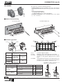
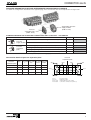
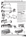
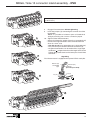
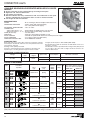
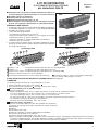
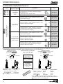
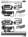
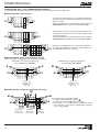
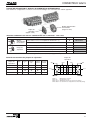
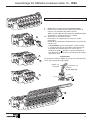
PNEUMATIC SPOOL VALVES ISLANDS
with individual connectors
ILOTS DE DISTRIBUTEURS PNEUMATIQUES
à raccordement individuel par connecteurs
size/ taille 15
IP20 - IP65
Installation manual
Manuel d'installation
IP20
IP65
881 57 875
MS-P575-1.R1
GB
FR
CONNECTOR size 15
SUMMARY
SOMMAIRE
Page
GB
Installation and maintenance in english ___________________________________ 3
Assembling of island _________________________________________________ 12
FR
Mise en service en français ____________________________________________ 15
Assemblage de l'îlot __________________________________________________ 24
A separate Declaration of Incorporation relating to EEC-Directive 89/392/EEC Annex II B is available on request.
Please provide acknowledgement number and serial numbers of products concerned.
This product complies with the essential requirements of the EMC-Directive 89/336/EEC and amendments. A
separate Declaration of Conformity is available on request.
Conformément à la directive CEE 89/392/CEE Annexe II B, une Déclaration d’incorporation peut être fournie sur
demande. Veuillez nous indiquer le numéro d’accusé de réception (AR) et les références ou codes des produits
concernés.
Ce produit est conforme aux exigences essentielles de la Directive 89/336/CEE sur la Compatibilité Electromagnétique,
et amendements. Une déclaration de conformité peut être fournie sur simple demande.
COPYRIGHT
2
© 2001 - ASCO/JOUCOMATIC - All rights reserved / Tous droits réservés
SPOOL VALVE ISLAND
Connectors
size 15
with individual electrical connection
with connectors size 15
■ Spool valve island with connectors with IP20 protection for installation in cabinets or with IP65 protection for direct mounting on
machines.
■ Compact, high performance unit.
■ Easy operation.
■ Modular design for on-site extension.
■ Assistance for diagnostic analysis and maintenance due to visual
indication of spool position, LED, reference and identification
labels, and manual override.
IP20
COMBINATIONS
●
●
●
Modules with up to 16 MEGA spool valves (22 spool valves on request) for
frame or DIN EN50022 rail mounting can be grouped together.
Optional mixing of:
- all spool valve functions,
- 6 or 8 mm O.D. instant fittings.
- Different types of manual override: impulse-type or locking push/turntype.
- Internal and external pilot pressure supply.
- Pressure separation plate and intermediate pressure supply module.
- Different connector types.
The IP20 version is provided with a partially integrated connection system
since the common ground of all pilot valves on the island is directly
established over jumpers (X).
IP65
IP20 connection
1
2
2
4
X
5
2
3
2
4
IP65 connection
2
4
2
4
2
4
2
4
2
4
2
4
2
3
5
82/84
4
1
2
3
4
5
3
2
6
4
4
1
1
4
Ports 1 - 3/5
: with instant fittings for flexible hose O.D. 10 mm or G1/4 thread
Ports 2 - 4
: with instant fittings for flexible hose O.D. 6 or 8 mm
Ports 12/14 - 82/84 : with instant fittings for flexible hose O.D. 4 mm or ØM5 thread
Frame (2 Ø4.2) or DIN rail mounting
6 Connectors size 15 - IP65 with CM6 (Pg7P) cable gland or
IP20 connectors with screw terminals and jumper for
with cable ends (2 or 5 m long)
common ground (X)
ELECTRICAL AND PNEUMATIC CHARACTERISTICS (see page 14)
ORDERING INFORMATION
The products are available as follows:
Pre-assembled and tested modules ready for installation 1
● Separate components 2 (to be mounted by customer)
●
1 Pre-assembled and tested module ready for operation
To order:
- Specify the MEGA spool valve island in the 2 or 3 reference lines according to the desired assembly:
● In the IP20 version (type C1), the spool valve islands are delivered with pre-assembled IP20 connectors and jumpers.
● In the IP65 version (type C0), the spool valve islands are delivered without the IP65 connectors.
- The connectors size 15 – IP65 must be ordered separately (see following page).
- Mounting and wiring accessories as required.
2 Separately supplied components
To order please specify the codes of all the components necessary to assemble
a spool valve island (type and quantity of each component):
■ Spool valves
■ End covers
■ Connectors IP20 - IP65
■ Pressure separation plate or intermediate pressure supply module
■ Mounting and pneumatic accessories
NOTE: To facilitate ordering the individual components of a spool valve island, use the configuration software which will help you
to completely fill in the reference lines for an island in accordance with the desired application and automatically specify the list of
all the necessary components. This software is available on CD-ROM (consult us).
3
CONNECTOR size15
ACCESSORIES: CONNECTORS SIZE 15
Adaptable on
MEGA spool valve
3 pins + earth
2 pins + earth
Description
Code
Connector size 15 – IP20, 3 pins + earth with integral
LED and peak voltage suppression, and screw terminals (clamping power: max. 1.5 mm²)
All types
(monostable
bistable
and 5/3)
5/2 monostable
(types M, S)
881 00 411
(X)
Set of 16 jumpers for common electrical ground (X) of MEGA spool valve
881 00 553
Standard connector size 15 – IP65, 2 pins + earth
with cable gland (Pg7P)
881 43 581
Standard connector size 15 – IP65, 2 pins + earth
with PVC cable ends. Length:
2m
881 43 567
Connector size 15 – IP65, 2 pins + earth with
integral LED indication and peak voltage
suppression, and PVC cable ends. Lengths:
2m
5m
881 43 580
881 43 593
Connector size 15 - IP65, 3 pins + earth
with cable gland (Pg7P)
3 pins + earth
for cabinet
installation
for direct mounting on machine (outside of cabinet)
IP65
IP20
Type
2 x 3/2 (type K)
5/2 bistable (type J)
5/3 neutral position
(types G, B, E)
881 00 240
Connector size 15 - IP65, 3 pins + earth with
peak voltage suppression, and PVC cable ends.
Lengths :
2m
881 22 430
Connector size 15 - IP65, 3 pins + earth with
integral LED indication and peak voltage
suppression, and PVC cable ends. Lengths :
2m
5m
881 00 446
881 00 447
Note:
If you wish to mix monostable and bistable spool valves on an island, we recommend using one type of connector with 3 pins +
earth which can be used for all spool valve types.
Identification of IP65 connectors with
cable ends
Pin assignment
Monostable spool valve
(view on pin/coil side)
14 (1)
(2) Common
ground
L
32
L
Connector assignment/identification
Pin 1
(+14)
: brown wire
Pin 2
(common) : blue wire
Pin
(earth)
: green/yellow wire
Lengths of 2m or 5m upon request.
(2) Common
ground
14 (1)
2 x 3/2 spool valves NC:
12B = 14 = pilot (B)
12A = 12 = pilot (A)
A
A
5/2 - 5/3 spool valves:
14 = pilot coil
12 = return coil
Pin assignment
Bistable spool valve or 2x3/2 or 5/3
(view on pin/coil side)
A
12 (3)
L
Non-rotatable connectors to be mounted with
cable directed towards
the top; the same is
applicable for the
pneumatic cables.
32
A
r
11
cto
ne page
n
o
e
c
20 t se
r IP en
Fo ignm
ass
Connector assignment/identification
881 22 430
Pin 1 (+14)
: brown wire
Pin 2 (common) : blue wire
Pin 3 (+12)
: black wire
Pin (earth)
: green/yellow wire
881 00 446/447
yellow wire
white wire
brown wire
green wire
Note: For power supply to a monostable, component do not connect
the black wire (881 22 430),brown wire (881 00 446/447).
L Lengths of 2m or 5m upon request.
4
CONNECTOR size15
ORDERING INFORMATION FOR MEGA ISLAND
MEGA island with
connectors size 15
1
1
678 C
4
▼ ▼ ▼ ▼
▼
▼
C1
*
Port connections: 2 - 4
Instant fittings Ø8mm O.D.
Instant fittings Ø6mm O.D.
Mixed (E & S) on island (1)
Type
E
S
P
Auxiliary manual override
(▼) impulse
(●) locking (push-turn)
Mixed (1 & 2) on island (1)
Type
1
2
P
Pilots supply 12/14
Internal
External
Mixed (I & E) on island (1)
Type
I
E
P
5
Spool valve position
6 7 8 9 10 11 12 13 14 15 16
Please indicate the type of
spool valve or accessory required
Type
C0
( ) Connectors size 15 - IP65 to be ordered separately
(see preceding page)
Port connections: 1 - 3 / 5
Instant fittings 10 mm O.D.
G1/4
3
▼
Island versions
Island without connector ( )
*
Island with connectors size 15 - IP20
with screw terminal
2
▼
MEGA ISLAND
Spool valve versions
2
Type
Q
G
Spool valves (functions)
Type
2 x 3/2 NC-NC
K
5/2 - Solenoid air operated pilot, spring return (monostable) S
5/2 - Solenoid air operated pilot, differential return (monostable) M
5/2 - Solenoid air operated pilot and return (bistable)
J
5/3 - Pressure held (W1)
G
5/3 - Pressure applied (W2)
B
5/3 - Exhaust released (W3)
E
Reserve module (to be placed at the left end of the island) A
Accessories (see next pages)
Type
Intermediate pressure supply module
D
(connection is identical to that selected for ports 1 - 3/5
of end covers, see opposite)
Pressure separation plate :
• Total blocking of 1, 3 and 5 (no connection) ..................
• Blocking of 3 and 5 (port 1 connection maintained) ......
• Blocking of 1 (ports 3 and 5 connections maintained) ..
X
Y
W
3
1
2
3
4
5
Spool valve position
6 7 8 9 10 11 12 13 14 15 16
Option
without option
00
..
99
other options
Island mounting
On frame
(2 x Ø4.2)
On rail
EN 50022 - DIN
Island delivery
Assembled
Unassembled
Assembled
Unassembled
Type
A
B
C
D
(1) Different spool valve versions can be mixed on an island. In this case:
- indicate type “P” in the basic reference 1
- fill in reference line 3
Spool valve versions (with mixed connections)
Connection
Manual
Pilots
Type
ports 2 - 4
override
12/14
Internal
1
(▼) impulse
Instant fittings
External
2
8 mm O.D.
Internal
3
(●) locking
External
4
Internal
5
(▼) impulse
External
6
Instant fittings
Internal
7
6 mm O.D.
(●) locking
External
8
!
How to fill in reference line 3 :
- Fill in only if different spool valve versions are to be
mixed on an island.
- Use the spool valve position numbers specified in
reference 2 .
- Repeat the type of accessory in the same position
number as specified in reference 2 .
: 678C0E2IQ00A
: AJJJJSGGXJS
MEGA island, without connector (*), designed for frame mounting, supplied assembled, comprising 9 spool valves for connection with
8 mm OD instant hose fittings, locking-type manual override, internal pilot.
Spool valve types:
- five bistable 5/2 spool valves, type J, in positions 2 to 5 and 10
- two monostable 5/2 spool valves, type S, in positions 6 and 11
- two 5/3 spool valves (W1), type G, in positions 7 and 8
- one reserve module (A) in position 1
- one pressure separation plate, total blocking, type X, in position 9
(*) Size 15 connectors, IP65, to be ordered separately (see preceding page)
ORDERING EXAMPLE
1
2
5
CONNECTOR size15
12 14 12 14 12 14 12 14
14
14
14
18
33,5
23
4,2
27
14
58
80
140
DIMENSIONS AND WEIGHTS
■ Spool valve island with connectors size 15 - IP20 (ref. C1)
21,5
33,5
L2 ±2 = 67 + (n x 18)
L1 = L2 + 13
6,5
11
6,5
107
18
49
26,5
5,5
5,5
1
2
3
3
2
2
2
2
2
2
3
2
2
5
82-84
12-14
12-14
4
1
4
4
4
4
4
4
4
1
2
2
4
4
15 26,5
5
82-84
4
2
2
4
4
4
2
4
2
4
2
3
5
82/84
4
1
4
4
107
28
= =
20
11
2
2
2
1
2
Ports 1 - 3/5 : with instant fittings for flexible hose O.D. 10 mm
or G1/4 thread
Ports 2 - 4 : with instant fittings for flexible hose O.D. 6 or
8 mm
Ports 12/14 - 82/84 : with instant fittings for flexible hose O.D. 4 mm or
ØM5 thread
4 Frame (2 Ø4.2) or DIN rail mounting
3
12 14 12 14 12 14 12 14
14
14
14
18
33,5
23
4,2
27
14
58
83
140
■ Spool valve island with connectors size 15 - IP65 (ref. C0)
21,5
33,5
L2 ±2 = 67 + (n x 18)
L1 = L2 + 13
6,5
11
6,5
110
18
49
26,5
5,5
5,5
3
2
3
2
2
2
2
2
2
2
2
3
5
82-84
12-14
12-14
1
4
4
4
4
4
4
4
4
1
15 26,5
5
82-84
4
110
28
= =
20
11
1
1 to 4 same as above
L2 (±2)
L1
Weight (kg)
6
4
139
152
0.650
5
157
170
0.760
6
175
188
0.870
Number of spool valves
7
8
9
10
193
211
229
247
206
224
242
260
0.980 1.090 1.200 1.310
11
265
278
1.420
12
283
296
1.530
13
301
314
1.640
14
319
332
1.750
15
337
350
1.860
16
355
368
1.970
CONNECTOR size15
END COVERS
The end covers assure the following functions:
- Island assembly: the bolts are fixed into the covers. The island is
tightened by hand with the knurled screws (S). There is no need for
tools.
- Choice of island mounting:
• on machine frame (2 Ø 4.2),
• on DIN EN 50022 rail (for cabinet installation).
- Pneumatic connection of the channelled ports of the island
(1 – 3/5 – 12/14 etc.)
■ Choice of island mounting
On machine frame
On DIN EN 50022 rail
L1
2 ØM4
■ Pneumatic connection
3/5
12/14
82/84
3/5
1
82/84
3/5
82/84
3
3
5
5
12/14
12/14
1
1
1
1
3/5
12/14
82/84
Port 1
Port 3/5
Port 12/14
Connection size
Port nos.
Type: Q
Type: G
Instant fittings for
flexible hose
Ø 10mm O.D.
G1/4
Instant fittings for
flexible hose
Ø 4mm O.D.
M5
Port 82/84
1
: Pressure supply for island
: Exhausts 3 and 5 channelled and connectable
: External pilot pressure supply. Necessary for use with
vacuum or if the general supply pressure is below
3 bar.
: Channelling and connection of the pilot exhausts for
installation of the island in protected environments
(food-processing industries, laboratories etc.)
Possibility of direct connection of a
silencer to each exhaust 3/5
■ Order codes for end covers
Description
Port connections 1 - 3/5 ( )
Type
Code
1 set of 2 end covers for
islands for frame
mounting
Instant fittings for 10mm O.D. hose
Q
881 57 901
G1/4 thread
G
881 57 903
1 set of 2 end covers for
islands for DIN rail
mounting
Instant fittings for 10mm O.D. hose
Q
881 57 859
G1/4 thread
G
881 57 861
*
Ø10
G1/4
( ) For port connections 12/14 and 82/84 see above table
*
: The codes in the grey shaded areas correspond to commonly used products which can be supplied rapidly.
7
CONNECTOR size15
SUPPLY WITH 1, 2 OR 3 DIFFERENT PRESSURES
A MEGA island is especially designed to be supplied with more than one pressure level.
■ Supply with 1 pressure (P1)
3
P1
5
1
3
P1
P1
1
5
P1
P1
1
5
• All other island versions are provided with 2 end covers for
choice of pressure supply side.
• For more than 8 spool valves or for simultaneous operation
of 5 spool valves, the unit must be supplied with pressure
from both sides.
5
3
1
3
• The island are provided with 2 end covers for choice of
pressure supply side (left or right side).
• For more than 8 spool valves or for simultaneous operation
of 5 spool valves, the unit must be supplied with pressure
from both sides.
5
3
5
3
5
3
1
1
• Units with more than 12 spool valves must be supplied
with pressure from three sides using an intermediate pressure supply module which should be placed in the middle.
P1
1
P1
■ Supply with 2 different pressures (P1-P2)
A pressure separation plate must be used (see different types)
• Supply with 2 different pressures with common exhausts
E
• Supply with 2 different pressures with separate exhausts
E1
E
5
3
P1
3
1
1
E2
3
5
P1
P2
Pressure separation
plate for blocking
flow path 1
(type: W)
5
3
1
5
1
P2
Pressure separation
plate for blocking
flow paths 1-3-5
(type: X)
■ Supply with 3 different pressures (P1-P2-P3)
E2
B
E1
P1
3
5
B
A
3
5
1
1
Spool valves
supplied at
pressure P1
Spool valves
supplied at
pressure P2
3
5
1
P2
8
Spool valves
supplied at
pressure P3
E3
P3
For this configuration use:
- 1 intermediate pressure supply module A .
- 2 pressure separation plates B . Choose between the
following versions:
• Ports 1 – 3 – 5 blocked to separate off the exhausts
(type X).
• Port 1 blocked to channel the exhaust of the whole island
(type W).
CONNECTOR size15
PRESSURE SEPARATION PLATE AND INTERMEDIATE PRESSURE SUPPLY MODULE
To obtain the configurations described on the opposite page, these accessories must be incorporated in the right order.
Intermediate pressure
supply module
(width: 27 mm)
Pressure
separation plate
(width: 9 mm)
STANDARD VERSIONS FOR ISLANDS WITH CONNECTORS SIZE 15, MULTIPOL – IP20 AND VCS
Type
Code
Ports 1 and 3 / 5 with instant fittings 10 mm O.D. (1)
D
881 57 819
Ports 1 and 3 / 5 with G1/4 thread (1)
D
881 57 821
Total blocking of ports 1 - 3 - 5 (no connection)
X
881 57 815
Blocking of ports 3 - 5 (port 1 connection maintained)
Y
881 57 817
Blocking of port 1 (ports 3 and 5 connections maintained)
W
881 57 816
No blocking (ports 1, 3 and 5 connections maintained)
V
881 57 818
Description
Intermediate
pressure
supply module
Pressure
separation
plate
(1) An exhaust silencer can be mounted to port 3 / 5 (see following page)
Construction details of pressure separation plate
Pressure
separation plate
Codes
pressure
separation plate
Type
881 57 815
X
✶
✶
✶
∇
881 57 817
Y
∇
✶
∇
∇
881 57 816
W
✶
∇
✶
∇
881 57 818
V
∇
∇
∇
∇
✶ : blocked
Flow path Flow path Flow path Flow path
1
3/5
12/14
82/84
∇ : remains opened
82/84
3/5
3
82/84
3/5
3
5
5
12/14
12/14
1
1
1
Port 1
Port 3/5
Ports 12/14
Ports 82/84
1
:
:
:
:
pressure supply
exhausts 3 and 5
external pilot pressure supply
connection of exhausts of pilot loop
9
CONNECTOR size15
PRESSURE SUPPLY OF PILOT VALVES
A MEGA spool valve is equipped on one side with a spacer sealing which also provides for a
selecting function:
- The spool valve can be adapted to either internal or external pilot pressure supply simply by
rotating this sealing.
- The position selected for each spool valve can be identified from the outside even after the spool
valves have been assembled to islands.
- Internal and external pressure supply can be mixed on one island.
- If the components are supplied separately, the spool valves are delivered with the sealing placed
in INT for internal pressure supply.
■ External pressure supply to pilot valves
■ Internal pressure supply to pilot valves
Identification underneath the spool valve
Identification underneath the spool valve
INT
EXT
INT
EXT
In this configuration:
The pilot valves are directly supplied with pressure by using the
supply pressure (1) in the middle of the spool valve.
The common pressure supply (spool valve and pilot valves) is
3 to 8 bar (2 to 8 bar with bistable 5/2 spool valves).
In this configuration:
- The spool valves on an island can be supplied with low pressure
and vacuum.
- The pilots and the spool valves on an island can be supplied with
pressure over 2 separate lines.
Supply pressure of pilot valves: 3 to 8 bar
(2 to 8 bar with bistable 5/2 spool valves)
Supply pressure of spool valves: -0.950 bar to +8 bar.
Connection of pilot pressure supply 12/14 at either one of the 2 end
covers.
MOUNTING AND PNEUMATIC ACCESSORIES
Accessory
1m
Description
Code
1m
881 57 858
5x1m
334 00 033
DIN EN50022 rail
x10
Set of 10 connecting bolts 18 mm long (for 5 spool valves)
(Note: Each spool valve is delivered with connecting bolts)
881 57 893
Set of 10 instant reducing fittings 8 / 6 mm O.D. (1)
881 57 887
x10
Plastic body
346 00 407
Sintered bronze body
346 00 002
Exhaust silencer, male thread (2)
Sintered bronze exhaust silencer for direct mounting to ports with
instant fittings 10 mm O.D. (3)
881 57 826
Set of 17 clip-on ID labels for spool valves and VCS connectors
(Note: each component is supplied with 2 ID labels at delivery)
881 57 851
(1) For mounting to ports 2 – 4 of spool valves with 8 mm O.D. instant fittings for 6 mm O.D. flexible tube
(2) Exhaust silencer for ports 3/5 of G1/4 threaded end covers (see page 7)
(3) Exhaust silencer for ports 3/5 of end covers with instant fittings 10 mm O.D. (see page 7)
: The codes in the grey shaded areas correspond to commonly used products which can be supplied rapidly.
10
CONNECTOR size15 - IP20
GENERAL
■ Simplified, screw terminal connector
■ IP20 protection, for cabinet installation
■ The size 15 connector fits all electrically-operated valves with two or three spade
terminal coils, to DIN 46244-A 2,8x0,5 (distance between pin centres : 9,4mm)
■ The IP20 version is equipped with semi-integrated interconnect for common electrical
system with jumpers (X)
■ This type of connector is recommended for spool valves mounted on multiple subbases
of series 519 - 520 - 521 or MEGA islands
ELECTRICAL CHARACTERISTICS
• Number of terminals
• Wire connection
• Wire cross-section
• Grounding
• Supply voltage
• Max. output current
• Visual indication/protection
• CE mark
:
:
:
:
:
:
:
3 + earth (pins 12, 14, common/GND)
3 screw terminals
0,14mm2 to 1,5mm2
screw terminal at bottom of connector
12 to 24 V CC
150mA per coil (3,6W)
2 Leds (14 : yellow, 12 : green) + protection diodes
Implantation on spool valve
Nota : Earthing for personal protection must be effected with the earth terminal on the
connector. (see below)
CHOICE OF EQUIPMENT
Description
Connector size 15 - IP20, 3 pins + earth
with integrated LED indicator and electrical protection
Screw terminal connection
L
Jumper for common ground (per unit)
For spool valve
series
519
520
521
578
519
520
521
578
(ØM5)
(ØG1/8)
(ØG1/4)
(MEGA)
(ØM5)
(ØG1/8)
(ØG1/4)
(MEGA)
L
(mm)
CODE
-
881 00 411
6,9
9,9
13,9
8,9
881
881
881
881
00
00
00
00
412
414
415
413
IP20 CONNECTORS
- Plug the IP20 connectors on spool valves.
- Place the jumpers (X) to establish the common ground for all pilot valves on the
unit.
X
Wiring
- Strip the wire ends.
- Connect the wires to the screw terminals of the IP20 connectors.
• 1 wire per coil (1 for monostable / 2 for bistable valve).
• 1 single wire per unit to connect the common ground (Z).
• Earth protection for the whole unit can also be effected with a single rigid,
striped wire ( ).
Visual indication
Return (12)
on bistable
MEGA
spool valve
to dual
integrated pilot
The IP20 connector is equipped with LEDs indicating that the pilots are supplied
with voltage.
Pilot (14)
Common (Z)
(1 single wire
per unit)
Led (14)
Led (12)
11
MEGA / Size 15 connector island assembly - IP65
18
A
B1
1
2
C
3
J
2mm
D
J
5a
14
4
4
2
12
5b
5
3
14
12 82/84 1
578 00 004
P(1): _ 0.9/3...8 bar
G
5a
5b
12 14
12 14
12 14
1 - Screw the two rows of posts (B1) into the
LH end-fitting (A) (the one without knurled
knobs) fitting one post in each row for each
spool valve to be installed (two 18 mm
posts are provided with each spool valve)
2 - End with two male-male posts on the RH
side (supplied with the end-fittings), with
the short threaded end on the post side (C)
3 - Install the RH end-fitting, taking care to
properly seat the seal (J) and pre-tighten
with the two knurled knobs, leaving a play
of 2 mm for installing the spool valves
4 - Identify each spool valve by its label with
the diagram and the code letter of the type
(e.g. S, M, G etc.), then check :
• that the selector seal (J) is in place
• properly orientated (INT or EXT) for the
desired piloting arrangement (see
corresponding section),
• that the seal is properly seated in its
housing
5 - Clip each spool valve (D) to the posts as
described in 5a and 5b
6 - Place the spool valves against each other
beginning at the LH side
Check that there is room to install the last
spool valve, with sufficient play
Check that all the spool valves are properly
clipped and aligned
7 - Secure the island assembly by screwing
tight with the knurled knobs. Do not use
pliers or any other tool!
8 - Fix the island to the support provided:
install on chassis with two M4 screws or
directly to symmetrical EN50022-DIN rail
9 - Couple the IP65 connectors and install
them on each spool valve
6
1mm
1mm
7
12 14 12 14 12 14 12 14 12 14
14
14
14
6
9
On chassis or machine frame
On symmetrical EN50022-DIN rail
L1
8
8
2 ØM4
12
MEGA / Size 15 connector island assembly - IP20
Assembly procedure identical to that for IP65 type
(up to Phase 7)
8
9
- Engage IP20 connectors without tightening
- Insert the jumpers (X) connecting the common for all the
island pilots
NOTE - it is possible to isolate two parts of the electrical
wiring by removing one common connection jumper
10 - Tighten all the IP20 connectors
- Secure the island to its support (chassis or symmetrical rail)
- Connect the IP20 connectors to the terminal block with
wires of 1.5 mm2 max
• One wire per coil (1 for monostable type / 2 for bistable type)
• Only one wire per island for common connection (Z)
• All ground connections can be made with a single rigid
conductor ( ) stripped over the entire length of the island
Tighten the ground screws on the lower part of each IP20
connector
8
9
Signalling
The IP20 connector is equipped with a power LED for each pilot
X
Return (12)
on bistable
type
Control (14)
Common
(one wire per island)
Led (14)
Led (12)
10
2
2
4
2
4
2
4
2
4
2
4
2
4
2
4
2
4
2
3
5
82/84
4
4
1
Z
13
CONNECTOR size15
JOINABLE SOLENOID AIR OPERATED MEGA SPOOL VALVES
GENERAL
■
■
■
■
Space saving due to new patented design and integral twin pilot.
High flow rate, reduced dimensions.
Low power consumption.
Quick installation and easy maintenance with visual indication of the spool
position, identification and reference labels as well as manual override.
■ Low weight for block installation.
SPECIFICATIONS
FLUIDS
OPERATING PRESSURE
: Air or neutral gas, filtered at 30µm, lubricated or not
: -0.95 to 8 bar (with external supply)
: 3 to 8 bar (with internal supply)
: -10°C to +50°C
ALLOWABLE TEMPERATURE
CONNECTION
- Spool valve (ports 2 - 4)
- End covers (ports 1 - 3 - 5)
FLOW (Qv at 6 bar)
FUNCTION
PILOT CONTROL
PILOT PRESSURE
VIBRATION FATIGUE LIMIT
: instant fittings for flexible hose 6 or 8 mm O.D.
: G1/4 thread or instant fittings 10 mm O.D.
: see table below
: 2x3/2 NC, monostable or bistable 5/2, 5/3
: solenoid air operated with internal or external pressure supply
: 2 or 3 bar to 8 bar (see table below)
: to EN 60068-2-6 standard
CONSTRUCTION
Body and end covers: glass-fibre reinforced synthetic material.
Internal parts: aluminium, stainless steel, zinc-plated steel, brass
and synthetic material.
Sealings: nitrile (NBR) and PUR.
Internal or external pilot pressure supply by selecting seal
Impulse-type or locking push/turn-type manual override.
Integral electrical pilot to NFC79300 (VDE 0580).
Encapsulated coil with flat terminals to DIN 46244 A 2.8 x 0.5
(spacing : 9.4 mm).
The bistable version is provided with an integral twin pilot placed
on one side of the valve with a single electrical connector for
reduced dimensions.
ELECTRICAL CHARACTERISTICS
Voltage
Insulation
class
Protection
degree
24 V DC
F
IP 65
Spool valve
Consumption
Electrical connection
monostable
1.6 W
bistable
1.5 W
2 flat terminals + earth
3 flat terminals + earth
CHOICE OF EQUIPMENT
Operators
Functions
Symbols
Type
2x3/2
K NC
4
14
S
5/2
5
5
5/3
2
5
12/14 82/84
E
3
14
4
2...8
Solenoid air
3
2
12
2
12
5
3
14
12 82/84 1
14
3...8
1
5
3
14
12 82/84 1
4
900
(550)
12
Solenoid air
14
Differential
1
4
5/2
5/3
2
Solenoid air
4
4...8
3...8
Spring
12
14
B
450
3
4
5/2
5/3
Spring
1
12/14 82/84
G
Solenoid air
Solenoid air
14
J
Return
(12)
CODES (24 V DC)
Pilot
pressure (M) Spool valve without connector
ports 2-4 with instant fittings
(bar)
6mm O.D.
8mm O.D.
2
12/14 82/84
M
Pilot
(14)
Flow
at 6 bar
(l/min)
(ANR)
2
5
3
14
12 82/84 1
12
Centre closed
W1
solenoid air operated
600
(550)
3...8
Centre open to pressure
W2
solenoid air operated
700
(550)
3...8
Centre open to exhaust
W3
solenoid air operated
750
(550)
3...8
(M) Manual override
▼ : impulse-type ● : locking, push/turn-type
(550) : Max. flow rate of 550l/min for the version with instant fittings for flexible hose O.D. 6mm.
14
▼
578 00 041
578 00 013
●
578 00 042
578 00 014
▼
578 00 030
578 00 002
●
578 00 036
578 00 008
▼
578 00 031
578 00 003
●
578 00 037
578 00 009
▼
578 00 029
578 00 001
●
578 00 035
578 00 007
▼
578 00 032
578 00 004
●
578 00 038
578 00 010
▼
578 00 033
578 00 005
●
578 00 039
578 00 011
▼
578 00 034
578 00 006
●
578 00 040
578 00 012
ILOT DE DISTRIBUTION
Connecteurs
taille 15
à raccordement électrique individuel
par connecteurs taille 15
■ Ilot proposé avec connecteurs IP20 pour installation en armoires ou
■
■
■
■
IP20
en version IP65 pour implantation directe au coeur des machines.
Ensemble compact et performant
Grande facilité de mise en oeuvre
Modularité permettant l’extension sur site
Aide au diagnostic et à la maintenance par visualisation de la position
du tiroir, Led, repérages, identifications et commande manuelle.
ENSEMBLES REALISABLES
●
●
●
Possibilité de constituer des îlots jusqu’à 16 distributeurs MEGA (22 distributeurs
sur demande) adaptables sur châssis ou sur rail symétrique EN 50 022
Possibilité de panacher à volonté:
- toutes fonctions de distributeurs
- raccordement à coupleurs Ø 6 ou 8 mm extr.
- le type de commande manuelle, à impulsion ou à accrochage (pousser-tourner)
- l’alimentation interne ou externe des pilotes
- plaque de séparation ou module d’alimentation intermédiaire
- différents types de connecteurs
La version IP20 est équipée d’une connectique partiellement intégrée
puisque le commun de tous les pilotes de l’îlot est directement établi par
les cavaliers de liaison (X).
IP65
connectique IP20
1
2
2
4
4
1
2
3
4
5
X
5
2
3
2
4
connectique IP65
2
4
2
4
2
4
2
4
2
4
2
4
2
3
5
82/84
4
1
1
3
2
6
4
4
Orifices 1 - 3/5
: à coupleurs pour tube souple Ø10 mm extr. ou taraudés G1/4
Orifices 2 - 4
: à coupleurs pour tube souple Ø6 ou 8 mm extr.
Orifices 12/14 - 82/84 : à coupleurs pour tube souple Ø4 mm extr. ou taraudés ØM5
Fixation sur châssis (2 Ø4,2) ou sur rail symétrique
Connecteurs IP20 à bornier à vis avec cavalier du commun (X)
6 Connecteurs taille 15 - IP65 à presse-étoupe CM6 (Pg7P)
ou à sortie de câble (longueur 2 ou 5m)
CARACTERISTIQUES ELECTRIQUES ET PNEUMATIQUES (voir page 26)
COMMANDE
Les produits peuvent être livrés de 2 façons différentes, au choix:
● En îlots assemblés, testés, prêts à être installés 1
● En composants fournis séparement 2 (montage à assurer par le client)
1 îlot livré assemblé, testé, en ordre de marche
Pour votre commande:
- Définir l’îlot MEGA constitué de 2 ou 3 lignes de référence en fonction de la composition souhaitée
● en version IP20 (type C1), les îlots sont livrés avec connecteurs IP20 + cavaliers montés
● en version IP65 (type C0), les îlots sont livrés sans les connecteurs IP65
- Les connecteurs taille 15 - IP65 sont à commander et sont livrés séparément (voir page suivante)
- Les éventuels accessoires de montage et raccordement
- Fourniture du manuel d’installation, code : 881 57 875
2 composants fournis séparément
Pour votre commande, définir les codes de l’ensemble des composants
nécessaires au montage de l’îlot (type et quantité de chaque composant) :
■ Distributeurs
■ Embouts
■ Connecteurs IP20 - IP65
■ Plaque de séparation ou module d’alimentation intermédiaire
■ Accessoires de montage et raccordement
■ Fourniture du manuel d’installation, code : 881 57 875
NOTA: Pour faciliter la rédaction de la commande d’îlot en composants séparés, un logiciel de configuration permet de construire
la référence complète de l’îlot en fonction de l’application souhaitée et de définir automatiquement la liste de tous les composants
nécessaires. Logiciel disponible sur CD-Rom (consulter votre point de vente habituel).
15
CONNECTEUR taille15
ACCESSOIRES CONNECTEURS TAILLE 15
Adaptable sur
distributeur MEGA
3 broches + terre
2 broches + terre
Tous types
(monostables
bistables
et 5/3)
5/2 monostable
(types M, S)
Désignation
Code
Connecteur taille 15 - IP20, 3 broches + terre avec
Led/visualisation et protection électrique intégrées
avec bornier à vis
(capacité de serrage 1,5 mm2 maxi)
881 00 411
(X)
Lot de 16 cavaliers de liaison du commun électrique (X) pour distributeur MEGA
881 00 553
Connecteur taille 15 - IP65 standard, 2 broches + terre
à presse-étoupe (Pg7P)
881 43 581
Connecteur taille 15 - IP65 standard, 2 broches + terre
à sortie de câble PVC, longueur :
2m
881 43 567
Connecteur taille 15 - IP65, 2 broches + terre avec
Led/visualisation et protection électrique intégrées
à sortie de câble PVC, longueur :
2m
5m
881 43 580
881 43 593
Connecteur taille 15 - IP65 standard, 3 broches + terre
à presse-étoupe (Pg7P)
3 broches + terre
pour montage
en armoire
pour montage hors armoire
directement sur machine
IP65
IP20
Type
881 00 240
2 x 3/2 (type K)
Connecteur taille 15 - IP65, 3 broches + terre avec
5/2 bistable (type J) protection électrique intégrées
5/3 à position neutre à sortie de câble PVC, longueur :
(types G, B, E)
2m
881 22 430
Connecteur taille 15 - IP65, 3 broches + terre avec
Led/visualisation et protection électrique intégrées
à sortie de câble PVC, longueur :
2m
5m
881 00 446
881 00 447
Remarque :
Si l’îlot comporte des distributeurs monostables et bistables mélangés, il est recommandé, dans un but de simplification, d’approvisionner
le même type de connecteur à 3 broches + terre, valable pour tous les types de distributeurs.
Repérage broches
Repérage broches
Identification des connecteurs
distributeur bistable ou 2x3/2 ou 5/3
distributeur monostable
IP65 à sortie de câble
(vue côté broches/bobine)
(vue côté broches/bobine)
14 (1)
(2) Commun
L
32
L
16
14 (1)
Distributeur 2 x 3/2 NF :
12B = 14 = commande (B)
12A = 12 = commande (A)
A
A
Distributeurs 5/2 - 5/3 :
14 = bobine commande
12 = bobine rappel
Repérage/Identification raccordement
Borne 1 (+14)
: fil marron
Borne 2 (commun) : fil bleu
(terre)
: fil vert/jaune
Borne
Longueur 2m ou 5m à la demande
A
(2) Commun
(3) 12
L
Connecteurs
non-orientables
le montage s’effectue
avec câbles dirigés vers
le haut, idem le câblage
pneumatique
32
A
ur
cte
ne 3
n
co e 2
ge ag
éra oir p
p
Re 0 : v
IP2
Repérage/Identification raccordement
881 22 430
Borne 1 (+14)
: fil brun
Borne 2 (commun) : fil bleu
Borne 3 (+12)
: fil noir
Borne (terre)
: fil vert/jaune
881 00 446/447
fil jaune
fil blanc
fil brun
fil vert
Nota : pour alimenter un composant monostable, ne pas
raccorder le fil noir (881 22 430), le fil brun (881 00 446/447)
L Longueur 2m ou 5m à la demande
CONNECTEUR taille15
REFERENCE ILOT MEGA
Ilot MEGA avec
connecteurs taille 15
2
1
1
678 C
▼
▼ ▼ ▼ ▼
▼
▼
( ) Les connecteurs taille 15 - IP65 sont à commander
séparément (voir page précédente)
Versions distributeurs
*
type
E
S
P
Commande manuelle auxiliaire type
(▼) à impulsion
1
(●) à accrochage(pousser-tourner)
2
Panachage (1 & 2) sur l’îlot (1)
P
Alimentation des pilotages 12/14 type
Interne
I
Externe
E
Panachage (I & E) sur l’îlot (1)
P
Raccordement orifices : 1 - 3 / 5
Coupleurs Ø10mm extr
G1/4
4
Position des distributeurs
5 6 7 8 9 10 11 12 13 14 15 16
-
Versions îlot
type
îlot sans connecteur ( )
C0
*
îlot avec connecteurs taille 15 - IP20
avec bornier à vis et cavaliers de liaison C1
Raccordement orifices : 2 - 4
Coupleurs Ø8mm extr
Coupleurs Ø6mm extr
Panachage (E & S) sur l’îlot (1)
3
type
Q
G
▼
ILOT MEGA
2
Pour chaque emplacement indiquer le type
de distributeur ou accessoire souhaité
Distributeurs (Fonctions)
type
2 x 3/2 NF-NF
K
5/2 - Cde électropneumatique Rappel ressort (monostable) S
5/2 - Cde électropneumatique Rappel différentiel (monostable)
M
5/2 - Cde et rappel électropneumatiques (bistable)
J
5/3 - Centre fermé (W1)
G
5/3 - Centre ouvert à la pression (W2)
B
5/3 - Centre ouvert à l'échappement (W3)
E
Emplacement libre (à placer à l’extrémité gauche de l’îlot) A
Accessoires (voir pages suivantes)
Module d’alimentation intermédiaire
(le raccordement est identique à celui sélectionné
pour les orifices 1 - 3/5 des embouts, voir ci-contre)
type
D
Plaque de séparation :
• Obturation complète 1 - 3 - 5 (aucune liaison) . . . . . . . .
• Obturation 3 - 5 (maintien liaison orifice 1) . . . . . . . . . . .
• Obturation 1 (maintien liaisons orifices 3 - 5) . . . . . . . . .
X
Y
W
3
1
2
3
4
Position des distributeurs
5 6 7 8 9 10 11 12 13 14 15 16
Option
sans option
00
..
99
options ultérieures
Fixation îlot
Sur châssis
(2 x Ø4,2)
Sur rail
EN 50022-DIN
Livraison îlot
Assemblé
Non assemblé
Assemblé
Non assemblé
type
A
B
C
D
(1) Possibilité de panacher les versions de distributeurs sur un même îlot, dans ce cas :
- indiquer le type «P» dans la référence de base 1
- remplir la ligne de référence 3
Versions des distributeurs (avec panachage)
Raccordement
Commande
Pilotages
orifices 2 - 4
manuelle
12/14
Interne
(▼) à impulsion
Coupleurs
Externe
Ø8 mm extr
Interne
(●) à accrochage
Externe
Interne
(▼) à impulsion
Externe
Coupleurs
Interne
Ø6 mm extr
(●) à accrochage
Externe
!
type
1
2
3
4
5
6
7
8
Règles d’écriture de la références 3 :
- A écrire uniquement en cas de panachage soudes versions de distributeurs
haité
- Respecter les numéros d’emplacement des distributeurs
définis dans la ligne de référence 2 .
- Répéter le type de l’éventuel accessoire sur le même
numéro de position tel que défini en référence 2
: 678C0E2IQ00A
: AJJJJSGGXJS
Ilot MEGA, sans connecteur (*), prévu pour fixation sur châssis, livré assemblé, comprenant 9 distributeurs à raccordement par
coupleurs pour tube souple Ø8mm extr, à commande manuelle à accrochage, pilotage interne. Type de distributeurs :
- 5 distributeurs 5/2 bistables, type J , sur positions n°2 à 5 et 10
- 2 distributeurs 5/2 monostables, type S, sur positions n°6 et 11
- 2 distributeurs 5/3 à centre fermé (W1), type G, sur positions n°7 et 8
- 1 emplacement libre (A) sur la position 1
- 1 plaque de séparation, obturation complète, type X, sur position n°9
(*) Les connecteurs taille 15, IP65, sont à commander séparément (voir page précédente)
EXEMPLE DE COMMANDE
1
2
17
CONNECTEUR taille15
12 14 12 14 12 14 12 14
14
14
14
18
33,5
23
4,2
27
14
58
80
140
ENCOMBREMENTS ET MASSES
■ Ilot avec connecteurs taille 15 - IP20 (réf. C1)
21,5
33,5
L2 ±2 = 67 + (n x 18)
L1 = L2 + 13
6,5
11
6,5
107
18
49
26,5
5,5
5,5
1
2
3
3
2
2
2
2
2
2
3
2
2
5
82-84
12-14
12-14
4
1
4
4
4
4
4
4
4
1
4
4
15 26,5
5
82-84
2
2
2
4
4
4
4
2
4
2
4
2
3
5
82/84
4
1
4
4
107
28
= =
20
11
2
2
2
2
1 Orifices 1 - 3/5 : à coupleurs pour tube souple Ø10 mm extr.
ou taraudés G1/4
: à coupleurs pour tube souple Ø6 ou 8 mm extr.
2 Orifices 2 - 4
3 Orifices 12/14 - 82/84 : à coupleurs pour tube souple Ø4 mm extr.
4
ou taraudés ØM5
Fixation sur châssis (2 Ø4,2) ou sur rail symétrique
12 14 12 14 12 14 12 14
14
14
14
18
33,5
23
4,2
27
14
58
83
140
■ Ilot avec connecteurs taille 15 - IP65 (réf. C0)
21,5
33,5
L2 ±2 = 67 + (n x 18)
L1 = L2 + 13
6,5
11
6,5
110
18
49
26,5
5,5
5,5
3
2
3
2
2
2
2
2
2
2
2
3
12-14
12-14
1
5
82-84
4
4
4
4
4
4
4
4
1
15 26,5
5
82-84
4
110
28
= =
20
11
1
1 à 4 identiques à ci-dessus
L2 (±2)
L1
Masse (kg)
18
4
139
152
0,650
5
157
170
0,760
6
175
188
0,870
Nombre de distributeurs
7
8
9
10
193
211
229
247
206
224
242
260
0,980 1,090 1,200 1,310
11
265
278
1,420
12
283
296
1,530
13
301
314
1,640
14
319
332
1,750
15
337
350
1,860
16
355
368
1,970
CONNECTEUR taille15
EMBOUTS D’EXTREMITE
Les embouts assurent les fonctions suivantes :
- assemblage de l’îlot : les colonnettes se fixent sur les embouts.
Les molettes (S) permettent le serrage complet de l’îlot, serrage
manuel, sans outil
- fixation de l’îlot, implantation au choix :
• sur châssis ou bâti de machine (2 Ø4,2)
• sur rail DIN-EN50022 (pour les montages en armoire)
- raccordement pneumatique des signaux communs de l’îlot (1 - 3/5 12/14 etc . . .)
■ Choix de l’implantation
Sur châssis ou bâti de machine
Sur rail symétrique DIN-EN50022
L1
2 ØM4
■ Raccordement pneumatique
3/5
12/14
82/84
3/5
1
82/84
3/5
82/84
3
3
5
5
12/14
12/14
1
1
1
1
Orifice 1
: alimentation de pression de l’îlot
Orifice
3/5
:
échappements 3 et 5 collectés et raccordables
type : Q
type : G
Orifice 12/14 : alimentation externe de la pression de pilotage.
à coupleurs pour
1
Nécessaire pour utilisation sur circuit de vide ou lorstube souple
G1/4
que
la pression d’alimentation générale est inférieure
3/5
Ø 10mm extr
à 3 bar
Orifice 82/84 : pour collecter et raccorder les échappements du cir
à coupleurs pour
12/14
cuit
de pilotage permettant l’installation de l’îlot en
M5
tube souple
82/84
milieu
protégé (industrie agro-alimentaire, salles blanches
Ø 4mm extr
Possibilité de connecter directement
etc . . .)
un silencieux sur chaque orifice
■ Codification du lot d’embouts
d’échappement 3/5
Raccordement orifices 1 - 3/5 ( ) Type
Code
Désignation
N° orifices
Taille raccordement
*
1 lot de 2 embouts
pour îlot à fixation
sur châssis
1 lot de 2 embouts
pour îlot à fixation
sur rail symétrique
à coupleurs pour Ø10mm extr.
Q
881 57 901
taraudés G1/4
G
881 57 903
à coupleurs pour Ø10mm ext .
Q
881 57 859
taraudés G1/4
G
881 57 861
r
Ø10
G1/4
( ) Raccordement des orifices 12/14 et 82/84 : voir le tableau ci-dessus
*
: Les codes grisés correspondent aux produits d'application courante, livrables dans un délai réduit
19
CONNECTEUR taille15
ALIMENTATION PAR 1, 2 OU 3 PRESSIONS DIFFERENTES
La conception des îlots MEGA permet de les alimenter par une ou plusieurs pressions différentes.
■ Alimentation par 1 pression (P1)
3
P1
5
5
3
1
P1
P1
1
5
3
P1
P1
1
5
• Pour les autres versions, les îlots sont toujours prévus avec
2 embouts permettant le choix du côté de raccordement de
l’arrivée de pression.
Au-delà de 8 distributeurs ou si 5 distributeurs doivent fonctionner
simultanément, il faut alimenter l’ensemble des 2 côtés.
5
3
1
3
• Les îlots sont toujours prévus avec 2 embouts permettant le
choix du côté de raccordement de l’arrivée de pression (côté
gauche ou droit).
• Au-delà de 8 distributeurs ou si 5 distributeurs doivent fonctionner
simultanément, il faut alimenter l’ensemble des 2 côtés.
5
3
5
3
1
1
• Au-delà de 12 distributeurs, il est nécessaire d’alimenter
l’ensemble en 3 points en adaptant un module d’alimentaP1 tion intermédiaire (à placer au centre).
1
P1
■ Alimentation par 2 pressions différentes (P1-P2)
Utiliser une plaque de séparation (voir les différents modèles)
• Alimentation par 2 pressions différentes
avec échappements communs
• Alimentation par 2 pressions différentes
avec échappements séparés
E
E1
E
5
3
P1
3
1
1
E2
3
5
P1
P2
Plaque de
séparation de la
canalisation 1
(type : W)
5
3
1
5
1
P2
Plaque de
séparation des
canalisations 1-3-5
(type : X)
■ Alimentation par 3 pressions différentes (P1-P2-P3)
E2
B
E1
P1
3
5
1
B
A
3
5
1
3
5
1
P2
distributeurs
alimentés à la
pression P1
20
distributeurs
alimentés à la
pression P2
distributeurs
alimentés à la
pression P3
E3
P3
Pour réaliser cette configuration, utiliser :
- 1 module d’alimentation intermédiaire A
- 2 plaques de séparation B , modèles au choix :
• avec obturation 1 - 3 - 5 pour séparer les échappements (type X)
• avec obturation 1 pour avoir les échappements communs
sur tout l’îlot (type W)
CONNECTEUR taille15
PLAQUE DE SEPARATION ET MODULE D’ALIMENTATION INTERMEDIAIRE
Pour réaliser les configurations ci-contre, il est nécessaire d’intégrer ces accessoires aux endroits opportuns.
Module d’alimentation
intermédiaire
(largeur 27 mm)
Plaque de
séparation
(largeur 9 mm)
VERSIONS STANDARD POUR ILOTS A CONNECTEURS taille 15, MULTIPOL - IP20 et VCS
Type
Code
avec orifices 1 et 3 / 5 à coupleurs Ø 10 mm extr. (1)
D
881 57 819
avec orifices 1 et 3 / 5 taraudés G1/4 (1)
D
881 57 821
obturation complète 1 - 3 - 5 (aucune liaison)
X
881 57 815
obturation 3 - 5 (maintien liaison orifice 1)
Y
881 57 817
obturation 1 (maintien liaisons orifices 3-5)
W
881 57 816
aucune obturation (maintien liaisons orifices 1 - 3 - 5)
V
881 57 818
Désignation
Module
d’alimentation
intermédiaire
Plaque de
séparation
(1) Possibilité de monter un silencieux d’échappement sur l’orifice 3/5 (voir page suivante)
Détail de construction des plaques de séparation
Plaque de
séparation
Code
plaque de
séparation
Type
Liaison
1
Liaison
3/5
Liaison
12/14
Liaison
82/84
881 57 815
X
✶
✶
✶
∇
881 57 817
Y
∇
✶
∇
∇
881 57 816
W
✶
∇
✶
∇
881 57 818
V
∇
∇
∇
∇
✶ : liaison obturée
∇ : liaison maintenue
82/84
3/5
3
82/84
3/5
3
5
5
12/14
12/14
1
1
1
Orifice 1
Orifice 3/5
Orifice 12/14
Orifice 82/84
1
:
:
:
:
alimentation de pression
échappements 3 et 5
alimentation externe de la pression de pilotage
raccordement des échappements du circuit de pilotage
21
CONNECTEUR taille15
ALIMENTATION PNEUMATIQUE DES ELECTROVANNES DE PILOTAGE
Le distributeur MEGA est équipé, sur une face latérale, d’un joint d’étanchéité intercomposant, qui
assure aussi la fonction de sélecteur :
- Possibilité d’adapter le distributeur en alimentation interne ou externe des électrovannes-pilotes
par simple rotation de ce joint.
- Position de sélection identifiable à l’extérieur du distributeur, même après assemblage en îlot.
- Possibilité de panacher sur un même îlot les fonctions alimentation interne et externe.
- En cas de livraison séparée des produits, les distributeurs sont fournis en alimentation interne
(joint placé en INT)
■ Alimentation externe des pilotes
■ Alimentation interne des pilotes
Identification sous le distributeur
Identification sous le distributeur
EXT
INT
INT
EXT
Dans cette configuration :
L’alimentation des pilotes est directe en utilisant la pression
d’alimentation (1) au centre du distributeur.
Pression d’alimentation commune (distributeur et pilotes) : 3 à 8 bar
(2 à 8 bar avec distributeurs 5/2 bistables)
Dans cette configuration l’îlot permet :
- l’utilisation des distributeurs sur circuit basse pression, y compris le vide
- l’alimentation du pilotage et de la puissance par 2 circuits séparés
Pression d’alimentation des pilotes : 3 à 8 bar
(2 à 8 bar avec distributeurs 5/2 bistables)
Pression d’alimentation des distributeurs : -0,950 bar à +8 bar
Raccordement de l’alimentation du circuit de pilotage, repérée 12 / 14,
au choix, sur l’un des 2 embouts d’extrémité
ACCESSOIRES DE MONTAGE ET RACCORDEMENT
Accessoire
1m
Désignation
Code
1m
881 57 858
5x1m
334 00 033
Rail symétrique EN50022-DIN
x10
Lot de 10 colonnettes de longueur 18mm (pour 5 distributeurs)
(en rappel : ces colonnettes sont fournies avec chaque distributeur)
881 57 893
Lot de 10 réductions à coupleurs Ø8 / Ø6mm extr (1)
881 57 887
x10
corps en plastique
346 00 407
corps en bronze fritté
346 00 002
Silencieux d’échappement, fileté G1/4 (2)
Silencieux d’échappement en bronze fritté,
à implantation directe dans orifice à coupleur Ø10mm extr (3)
881 57 826
Lot de 17 étiquettes d’identification, clipsables sur distributeur et connecteur VCS
(en rappel : 2 étiquettes sont fournies avec chaque composant)
881 57 851
(1) A adapter sur les orifices 2 - 4 des distributeurs à sorties à coupleurs Ø8mm extr. permettant de raccorder par tube souple Ø 6mm extr.
(2) Silencieux d’échappement adaptable sur orifices 3/5 des embouts taraudés G1/4
(3) Silencieux d’échappement adaptable sur orifices 3/5 des embouts à coupleurs Ø10mm extr.
: Les codes grisés correspondent aux produits d'application courante, livrables dans un délai réduit
22
CONNECTEUR taille15 - IP20
GENERALITES
■ Connecteur à raccordement simplifié, à bornier à vis
■ Degré de protection IP20, pour installation en armoire
■ Ce connecteur taille 15 s’adapte sur toute électrovanne ou électrodistributeur avec
bobine à 2 ou 3 broches plates DIN 46244-A 2,8x0,5 (espacement broches : 9,4mm)
■ La version IP20 est équipée d’une connectique semi intégrée du commun électrique
à l’aide de cavaliers (X)
■ Ce type de connecteur est recommandé pour les distributeurs à montage sur embases multiples séries 519 - 520 - 521 ou les îlots MEGA
CARACTERISTIQUES ELECTRIQUES
• Nombre de broches
• Connexion des fils
• Capacité de serrage
• Mise à la terre
• Tension d’alimentation
• Courant maxi de sortie
• Visualisation/protection
• Matériel certifié CE
:
:
:
:
:
:
:
3 + terre (broches 12, 14, commun/GND)
bornier à 3 bornes à vis
0,14mm2 à 1,5mm2
par borne à la partie inférieure
12 à 24 V CC
150mA par bobine (3,6W)
2 Led (14 : jaune, 12 : vert) + diodes de protection
Implantation sur distributeur
Nota : la mise à la terre pour la protection des personnes est à réaliser directement sur
le connecteur via la borne de masse, prévue à cet effet. (voir ci-dessous)
SELECTION DU MATERIEL
Désignation
Connecteur taille 15 - IP20, 3 broches + terre
avec Led de visualisation et protection électrique intégrées
Raccordement par bornier à vis
L
Cavalier de liaison (X) du commun électrique, à l’unité
Pour distributeur
série
519
520
521
578
519
520
521
578
(ØM5)
(ØG1/8)
(ØG1/4)
(MEGA)
(ØM5)
(ØG1/8)
(ØG1/4)
(MEGA)
L
(mm)
CODE
-
881 00 411
6,9
9,9
13,9
8,9
881
881
881
881
00
00
00
00
412
414
415
413
RACCORDEMENT DES CONNECTEURS IP20
- Embrocher les connecteurs IP20 sur les distributeurs
- Placer les cavaliers (X) qui établissent la liaison du commun électrique à tous
les pilotes de l’ensemble
X
Câblage
- Dénuder les extrémités des conducteurs
- Raccorder les connecteurs IP20 à bornier à vis
• 1 fil par bobine (1 pour monostable / 2 pour MEGA bistable)
• 1 seul fil par ensemble pour le raccordement du commun (Z)
• Possibilité de raccorder toutes les masses par un conducteur rigide ( )
dénudé sur toute la longueur de l’ensemble.
Signalisation
Le connecteur IP20 est équipé d’une led de visualisation de mise sous tension de
chaque pilote
Rappel (12)
sur distributeur
MEGA bistable
à double pilote
intégré
Commande (14)
Commun (Z)
(1 seul fil
par ensemble)
Led (14)
Led (12)
23
Assemblage îlot MEGA/connecteurs taille 15 - IP65
18
A
B1
1
2
C
3
J
2mm
D
J
5a
14
4
4
2
12
5b
5
3
14
12 82/84 1
578 00 004
P(1): _ 0.9/3...8 bar
G
5a
5b
12 14
12 14
12 14
6
1mm
1 - Visser les 2 rangées de colonnettes (B1)
sur l’embout gauche -celui qui n’a pas de
molettes- (A) en plaçant autant de
colonnettes que de distributeurs à monter
(2 colonnettes de 18mm sont fournies avec
chaque distributeur)
2 - Terminer par les 2 colonnettes mâle-mâle
d’extrémité droite (fournies avec les
embouts), la petite longueur filetée côté
colonnettes (C)
3 - Monter l’embout droit en s’assurant de la
mise en place correcte du joint
d’étanchéité (J) et pré-serrer à l’aide des
2 molettes en laissant un jeu de 2mm
pour le montage des distributeurs
4 - Identifier chaque distributeur par son
étiquette avec schéma, code et lettre-repère
du type (ex. : S, M, G, . . .), puis s’assurer :
• de la présence du joint sélecteur (J),
• de la bonne position en «INT» ou «EXT»
suivant l’alimentation de pilotage souhaitée
(voir chapitre correspondant)
• de la mise en place correcte du joint dans
son logement
5 - Clipser chaque distributeur (D) sur les
colonnettes comme décrit en (5a) et (5b)
6 - Plaquer les distributeurs les uns contre les
autres vers la gauche.
S’assurer qu’il reste un espace avec un jeu
suffisant pour monter le dernier distributeur.
S’assurer du clipsage complet de tous les
distributeurs et de leur bon alignement
7 - Serrage de l’ensemble de l’îlot par vissage
manuel énergique des molettes. Ne pas
utiliser de pince multiprise, ni autre outil !
8 - Fixer l’îlot sur le support prévu : montage sur
chassis à l’aide des 2 vis ØM4 ou directement
sur rail symétrique EN50022-DIN
9 - Raccorder les connecteurs IP65 et les
monter sur chaque distributeur
1mm
7
12 14 12 14 12 14 12 14 12 14
14
14
14
6
9
Sur châssis ou bâti de machine
Sur rail symétrique EN50022-DIN
L1
8
8
2 ØM4
24
Assemblage îlot MEGA/connecteurs taille 15 - IP20
Procédure d’assemblage identique à IP65 (jusqu’à la phase 7)
8 - Embrocher les connecteurs IP20 sans les serrer
9 - Enfoncer les cavaliers (X) qui établissent la liaison du
commun sur l’ensemble des pilotes de l’îlot
NOTA - il est possible d’isoler 2 parties du câblage électrique
en enlevant 1 cavalier de liaison du commun
10 - Serrer tous les connecteurs IP20
- Fixer l’îlot sur le support prévu (chassis ou profilé
symétrique)
- Raccorder les connecteurs IP20 à bornier à vis par des fils
1,5mm2 maxi
• 1 fil par bobine (1 pour monostable / 2 pour bistable)
• 1 seul fil par îlot pour le raccordement du commun (Z)
• Possibilité de raccorder toutes les masses par un
conducteur rigide ( ) dénudé sur toute la longueur de
l’îlot. Serrer les vis de masse à la partie basse de chaque
connecteur IP20
8
9
Signalisation
Le connecteur IP20 est équipé d’une led de visualisation des
mises sous tension de chaque pilote
X
Rappel (12)
sur bistable
Commande (14)
Commun
(1 seul fil par îlot)
Led (14)
10
Led (12)
2
2
4
2
4
2
4
2
4
2
4
2
4
2
4
2
4
2
3
5
82/84
4
4
1
Z
25
CONNECTEUR taille15
DISTRIBUTEURS ASSOCIABLES MEGA
A COMMANDE ELECTROPNEUMATIQUE
GENERALITES
■
■
■
■
Grande compacité grâce à une architecture novatrice brevetée et au double-pilote intégré
Débit élevé, encombrement réduit
Faible consommation électrique
Mise en oeuvre rapide et maintenance facilitée par visualisation de la position
du tiroir, par Led, identification, repérages et commande manuelle auxiliaire
■ Faible poids pour installations embarquées
SPECIFICATIONS
FLUIDE DISTRIBUE
PRESSION D’UTILISATION
: Air ou gaz neutre, filtré 30µm, lubrifié ou non
: -0,95 à 8 bar (en alimentation externe)
: 3 à 8 bar (en alimentation interne)
: -10°C à +50°C
TEMPERATURE ADMISSIBLE
RACCORDEMENT
- Distributeur (orifices 2 - 4)
- embouts (orifices 1 - 3 - 5)
DEBIT (Qv à 6 bar)
FONCTION
PILOTAGE
PRESSION DE COMMANDE
TENUE AUX VIBRATIONS
: à coupleurs pour tube souple Ø6 ou Ø8 mm extr.
: taraudés G1/4 ou à coupleurs Ø10 mm extr.
: voir tableau ci-dessous
: 2x3/2 NF, 5/2 monostable ou bistable, 5/3
: électropneumatique à alimentation interne ou externe
: 2 ou 3 bar à 8 bar (voir tableau ci-dessous)
: conforme à la norme EN 60068-2-6
CONSTRUCTION
Corps et embouts de raccordement : polymères techniques + F.V.
Pièces internes : aluminium, acier inox, acier zingué, laiton et
polymères techniques
Joints d’étanchéité : NBR et PUR
Joint sélecteur pour alimentation interne ou externe
Commande manuelle à impulsion ou à accrochage pousser-tourner
Pilote électrique intégré conforme à NFC79300
Bobine surmoulée à sorties par broches plates DIN46244
A 2,8 x 0,5 (espacement des broches : 9,4 mm)
La version bistable est équipée d’un double-pilote intégré, placé
du même côté avec une connectique regroupée pour une solution
plus compacte
CARACTERISTIQUES ELECTRIQUES
Tension
Classe
d’isolation
Degré de
protection
24 V CC
F
IP 65
Distributeur
Consommation
Raccordement électrique
monostable
1,6 W
bistable
1,5 W
2 broches plates + terre
3 broches plates + terre
SELECTION DU MATERIEL
Organes de pilotage
Fonctions
Symboles
Type
K
2x3/2
NF
4
14
S
5/2
5
14
B
E
5/3
5/3
5/3
3
2
5
4
12
14
3
2
12
2
12
5
3
14
12 82/84 1
14
4
Ressort
Electropneumatique
Différentiel
Electropneumatique
Electropneumatique
4...8
3...8
900
(550)
3...8
2...8
1
5
3
14
12 82/84 1
4
Electropneumatique
450
1
4
5/2
14
Ressort
2
5
12/14 82/84
G
3
12
5/2
12/14 82/84
J
Electropneumatique
1
4
14
Rappel
(12)
2
12/14 82/84
M
Commande
(14)
CODES (24 V CC)
Débit
Pression
Distributeur
sans connecteur
à 6 bar
de
(M)
orifices 2-4 à coupleurs
(l/min) commande
(ANR)
(bar)
Ø6mm extr.
Ø8mm extr.
2
5
3
14
12 82/84 1
12
Centre fermé
W1
cdes électropneumatiques
600
(550)
3...8
Centre ouvert à la pression
W2
cdes électropneumatiques
700
(550)
3...8
Centre ouvert à l'échappement
W3
cdes électropneumatiques
750
(550)
3...8
(M) type de commande manuelle ▼ : à impulsion ● : à accrochage, pousser-tourner
(550) : Débit maximal à 550l/min en version à raccordement pour tube Ø6mm extr.
26
▼
578 00 041
578 00 013
●
578 00 042
578 00 014
▼
578 00 030
578 00 002
●
578 00 036
578 00 008
▼
578 00 031
578 00 003
●
578 00 037
578 00 009
▼
578 00 029
578 00 001
●
578 00 035
578 00 007
▼
578 00 032
578 00 004
●
578 00 038
578 00 010
▼
578 00 033
578 00 005
●
578 00 039
578 00 011
▼
578 00 034
578 00 006
●
578 00 040
578 00 012
CONNECTEUR taille15
27
serves the world with a network of strategically-located facilities
www.ascojoucomatic.com
EUROPE
■ BELGIUM
ASCO/JOUCOMATIC BENELUX
Lusambostraat 53, Rue de Lusambo
1190 BRUSSEL / BRUXELLES
Tel.(32) 2 / 333 02 50 - Fax (32) 2 / 333 02 51
E-mail: [email protected]
■ CZECH REPUBLIC
ASCO JOUCOMATIC S.R.O.
Udolni 15 - CZ 140 00 - PRAHA 4
Tel. (420) 2 / 61315 411 - Fax (420) 2 / 61315 444
E-mail: [email protected]
■ FRANCE
ASCO JOUCOMATIC SA
32, Av. Albert 1er - B.P. 312 - 92506 RUEIL Cedex
Tel.(33) (0) 1 47 14 32 00 - Tx 634 228 - Fax (33) (0) 1 47 08 53 85
www.ascojoucomatic.fr
■ GERMANY
ASCO JOUCOMATIC GmbH & Co.
Otto-Hahn-Str. 5 - 75248 ÖLBRONN-DÜRRN
Tel.(49) 7237 9960 - Fax (49) 7237 9961
E-mail: [email protected]
■ GREAT BRITAIN
ASCO JOUCOMATIC Ltd.
2 Pit Hey Place, West Pimbo - SKELMERSDALE - Lancashire WN8 9PG
Tel.(44) 1 / 695 71 36 00 - Fax (44) 1/ 695 71 36 33
E-mail: [email protected]
■ HUNGARY
ASCO/JOUCOMATIC (ASCO Kft.)
Bogancs u. 1 - 3 - 1151 BUDAPEST
Tel.(36) 1 / 306 41 00 - Fax (36) 1 / 306 09 80
E-mail: [email protected]
■ ITALY
ASCO JOUCOMATIC SpA
Via Zambeletti - ang. Via Ghisallo - 20021 BARANZATE di BOLLATE (MI)
Tel.(39) 02 / 35 693 1 - Fax (39) 02 / 35 693 300
E-mail: [email protected]
■ NETHERLANDS
ASCO/JOUCOMATIC (ASCO CONTROLS BV)
Industrielaan 21 - 3925 BD - SCHERPENZEEL
Tel.(31) 33 277 7911 - Fax (31) 33 277 7888
E-mail: [email protected]
■ POLAND
ASCO JOUCOMATIC Sp. z o.o.
Ul. Konstruktorska 11a
02 673 WARSAW
Tel.(48) 22 / 54 85 280 - Fax (48) 22 / 54 85 288
E-mail: [email protected]
■ PORTUGAL
ASCO/JOUCOMATIC (FLUIDOCONTROL S.A.)
Rua Eng° Ferreira Dias, 938 - AZ2
4100 - 246 PORTO
Tel.(351) 22 / 619 08 57 - Fax (351) 22 / 619 08 58
E-mail: [email protected]
■ SPAIN
ASCO/JOUCOMATIC (FLUIDOCONTROL S.A.)
39700 CASTRO-URDIALES (Cantabria)
Tel.(34) 942 87 61 00 - Fax (34) 942 86 33 23
E-mail: [email protected]
■ SWEDEN
ASCO/JOUCOMATIC (ASCO AB)
Albanoliden 3-5 - 506 30 BORÅS
Tel.(46) 33 / 108 000 - Fax (46) 33 / 108 080
E-mail: [email protected]
■ SWITZERLAND
ASCO/JOUCOMATIC Switzerland (ASCO CONTROLS AG)
Schaftenholzweg 16 - 2557 STUDEN / BIEL-BIENNE
Tel.(41) 32 / 374 45 10 - Fax (41) 32 / 374 45 11
E-mail: [email protected]
■ TURKEY
ASCO/JOUCOMATIC TURKEY
Bayar Cd. Gülbahar Sk. - Perdemsaç Plaza N°17/97
81090 KOZYATAGI - ISTANBUL
Tel.(90) 216 / 464 07 70 - Fax (90) 216 / 464 07 71
E-mail: [email protected]
AMERICAS
■ BRAZIL
ASCO/JOUCOMATIC (ASCOVAL ind. e. com. Ltda.)
Rod. Pres. Castelo Branco Km 20 - Jd. Sta. Cecilia
CEP 06465-300 BARUERI - SAO PAULO
Tel.(55) 11 / 4195 5333 - Fax (55) 11 / 4195 3970
E-mail: [email protected]
■ CANADA
ASCO/JOUCOMATIC (ASCOVALVE Inc)
Airport Road - PO Box 160 - BRANTFORD, ONTARIO N3T 5M8
Tel.(1) 519 / 758 2700 - Fax (1) 519 / 758 5540
E-mail: [email protected]
■ MEXICO
ASCO/JOUCOMATIC (ASCOMATICA S.A. de C.V.)
Bosques de Duraznos 65 - 1003 A
Bosques de las Lomas - 11700 MEXICO D.F.
Tel.(52)5 / 596 77 41 - Fax (52)5 / 596 77 19
E-mail: [email protected]
■ USA
ASCO (Valve, Inc)
50 Hanover Road - FLORHAM PARK, NJ 07932
Tel.(1) 973 / 966 2000 - Fax (1) 973 / 966 2628
E-mail: [email protected]
AFRICA & MIDDLE EAST
■ SOUTH AFRICA
ASCO/JOUCOMATIC (ASCOREG)
P.O. Box 737 - 3 Commerce Place
Eastgate Ext. 12, Sandton - GAUTENG
Tel. (27) 11 / 444 22 13 - Fax (27) 11 / 444 22 21
E-mail: [email protected]
■ UNITED ARAB EMIRATES
ASCO/JOUCOMATIC MIDEAST
PO Box 17034 - Jebel Ali free zone - DUBAI
Tel.(971) 4 / 883 44 94 - Fax (971) 4 / 883 44 95
E-mail: [email protected]
ASIA & OCEANIA
ASCO/JOUCOMATIC REPRESENTATIVES (see web)
Algeria - Argentina - Austria - Bolivia - Bulgaria - Cameroon - Chile - China - Colombia - Costa Rica - Croatia - Denmark - Ecuador - Egypt - Finland
- Greece - Guadeloupe - Guatemala - Honduras - Iceland - Ireland - Israël - Ivory Coast - Luxemburg - Martinique - Morocco - Nicaragua - Norway - Pakistan
- Panama - Peru - Porto Rico - Reunion Island and Madagascan Rep. - Romania - Russia - El Salvador - Saudi Arabia - Senegal - Slovakia - Slovenia - Tunisia
- Ukraine - Uruguay - Venezuela - F.R. Yugoslavia (all other countries, contact E-mail : [email protected])
Local distributor - Distribué par - Ihr Ansprechpartner
:
4CV.GB-08/02
■ AUSTRALIA
ASCO/JOUCOMATIC (ASCOMATION Pty. Ltd.)
Unit 12, Allambie Grove Business Park
25 Frenchs Forest Road East - FRENCHS FOREST - N.S.W. 2086
Tel.(61) 2 / 9451 7077 - Fax (61) 2 / 9451 9924 - E-mail: [email protected]
■ NEW ZEALAND
ASCO/JOUCOMATIC (ASCOMATION Pty. Ltd.)
3 Vega place - Mairangi Bay
PO. Box 302 441 - North Harbour - AUCKLAND
Tel.(64) 9 / 478 0192 - Fax (64) 9 / 478 0193
E-mail: [email protected]
- 2C50902
■ SINGAPORE
ASCO/JOUCOMATIC (ASCO ASIA)
Blk 4008, Ang Mo Kio Ave.10 - 04-17/22, Techplace1
SINGAPORE 569 625
Tel.(65) 556 11 00 - Fax (65) 556 00 11
E-mail: [email protected]
■ TAIWAN R.O.C.
ASCO/JOUCOMATIC (ASCO ASIA)
5th. fl, N°2 Jen Ai Road - Section 4 - TAIPEI 10650
Tel.(886) 2 / 2325 9555 - Fax (886) 2 / 2702 6009
E-mail: [email protected]
383 45 81
■ HONG KONG
ASCO/JOUCOMATIC (ASCO ASIA)
Room 3904, Central Plaza, 18 Harbour Road - WANCHAI
Tel.(852) 2343 8580 - Fax (852) 2790 1771
E-mail: [email protected]
■ INDIA
ASCO/JOUCOMATIC (ASCO INDIA Ltd.)
147 Karapakkam village - MADRAS 600 096
Tel. (91) 44/496 0455 - Fax (91) 44/496 2270
E-mail: [email protected]
■ JAPAN
ASCO/JOUCOMATIC (ASCO JAPAN Co. Ltd.)
1-20 Takahata-Cho Nishinomiya - HYOGO 663-8202
Tel. (81) 798 65 6361 - Fax (81) 798 63 4443
E-mail: [email protected]
■ KOREA
ASCO/JOUCOMATIC (ASCO ASIA)
6 fl. Chunglim Bldg, 38-30 Samsung-dong
Kangnam-Ku - SEOUL 135 090
Tel.(82) 2 / 515 2485 - Fax (82) 2 / 540 3250
E-mail: [email protected]


![FCB Modem Software User Manual [ 002706 ]](http://vs1.manualzilla.com/store/data/005828465_1-1c68a7b174dea68ac1a15f0d4e9b2df8-150x150.png)