1
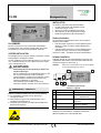
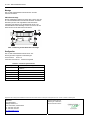
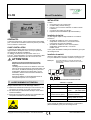
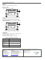
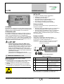
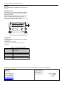
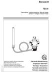
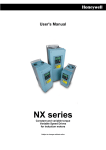
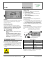
IF-LON Mounting Instructions INSTALLATION The delivery comes complete with the following parts: ® IF-LON LONWORKS Interface; USB cable (0.8 meter long); Clamp for connection of the IF-LON Interface to the LONWORKS network; A DIN rail-mounting bracket; These Mounting Instructions (MU1Z-0974GE51). Software Installation GENERAL The CentraLine IF-LON LONWORKS® Interface can be used to connect CentraLine controllers (via their USB port) with LONWORKS ® networks. BEFORE INSTALLATION All wiring must comply with local electrical codes and ordinances or as specified on installation wiring diagrams. 2 IF-LON network wiring can be sized from 1.5 to 0.34 mm , depending on the application. The maximum length of wire from the CentraLine controller to the IF-LON is 0.8 m. The necessary driver software is already installed on the CentraLine controller. If you have installed CARE on a PC having Windows 7 as the operating system, no further user action is necessary. If you have installed CARE on a PC having Windows XP as the operating system, you will have to install usbnet. See CARE – Installation Guide (EN1Z-0964GE51) for details. Hardware Installation Using the supplied USB cable, connect the IF-LON Interface to a free USB port of the CentraLine controller (see Fig. 1). NOTE: In performing this action, it is not necessary to remove the CentraLine controller from power. CAUTION 5 1 EMI Noise Introduction. Risk of erratic system operation. Keep wiring at least 300 mm away from large inductive loads such as motors, line starters, lighting ballasts and large power distribution panels. During installations, try to avoid areas of high EMI noise. Run IF-LON wiring separately from 50 Vac or greater power wiring. 2 3 4 Fig. 1. Connecting the IF-LON WARNING / CAUTION Risk of electric shock or equipment damage! ► Disconnect the power supply before making connections to or removing connections from the IF-LON’s terminals. ► Do not reconnect the power supply until you have completed the installation. ► Observe precautions for handling electrostatic sensitive devices. Table 1. Legend no. term remarks 1 LonWorks® connector 2-pin: TP/FT-10 2 STATE LED (green) OFF: ON: not ready to operate ready to operate 3 SERVICE LED (yellow) Display Service Pin Neuron processor 4 Service Pin Button Manual activation of a Service Pin message 5 USB connector Use supplied USB cable See also IF-LON Interface – Installation Instructions (MU1B0538GE51) for more-detailed information. Copyright © 2013 Honeywell GmbH ● All Rights Reserved MU1Z-0974GE51 R0913 IF-LON – MOUNTING INSTRUCTIONS Mounting The IF-LON Interface is suitable for DIN rail mounting. DIN Rail Mounting A DIN rail mounting bracket (see Fig. 2) can be used to mount the IF-LON Interface onto a DIN rail. After attaching the bracket to the back of the IF-LON Interface (using two PZ2 screws for plastic, included), the device can be simply clicked onto the DIN rail. 66 3.5 Fig. 2. Bracket for DIN rail mounting Configuration The IF-LON Interface is supplied with the following presettings: Transceiver ID: TP/FT-10 Automatic Flush Cancel: Box checked Table 2. Technical specifications term remarks Bus interface USB-conform as per USB specification 1.1, 12 Mbit/sec Network interface EIA 709-conform, TP/FT-10 Operating temperature +0 °C to +70 °C Storage temperature -45 °C to +85 °C Max. humidity 90% at +50 °C, non-condensing Listings CE mark and FCC mark Manufactured for and on behalf of the Environmental and Combustion Controls Division of Honeywell Technologies Sàrl, Rolle, Z.A. La Pièce 16, Switzerland by its Authorized Representative: CentraLine Honeywell GmbH Böblinger Strasse 17 71101 Schönaich, Germany Tel. +49 7031 637 845 Fax +49 7031 637 740 [email protected] www.centraline.com CentraLine Honeywell Control Systems Ltd. Arlington Business Park UK-Bracknell, Berkshire RG12 1EB Phone: +44 13 44 656 565 Fax: +44 13 44 656 563 [email protected] www.centraline.com Printed in Germany. Subject to change without notice. MU1Z-0974GE51 R0913 IF-LON Montageanleitung INSTALLATION Die Lieferung beinhaltet folgende Bestandteile: IF-LON LONWORKS® Schnittstellenkonverter; USB-Kabel (Länge: 0,8 m); Klemme für LONWORKS-Netzwerk Anschluß; Eine Halterung für die DIN-Schienenmontage; Diese Montageanleitung (MU1Z-0974GE51). Software Installation ALLGEMEINES Mit dem CentraLine IF-LON LONWORKS® Schnittstellenkonverter lassen sich CentraLine Regler (über deren USBSchnittstelle) mit LONWORKS ® Netzwerken verbinden. VOR DER INSTALLATION Die Verdrahtung muß nach den gültigen Vorschriften und den Anschlußplänen durchgeführt werden. Je nach Applikation können Aderquerschnitte von 1,5 bis 0,34 mm2 verwendet werden. Der max. Abstand zwischen Regler und IF-LON beträgt 0,8 m. ACHTUNG Die erforderliche Treibersoftware ist auf dem CentraLine Regler bereits installiert. Falls Sie CARE auf Ihrem PC mit dem Betriebssystem Windows 7 haben, sind keine weiteren Maßnahmen erforderlich. Falls Sie CARE auf Ihrem PC mit dem Betriebssystem Windows XP haben, müssen Sie usbnet installieren. Siehe auch CARE – Installation Guide (EN1Z-0964GE51). Hardware Installation Schließen Sie den IF-LON Schnittstellenkonverter über das mitgelieferte USB-Kabel an eine freie USB-Schnittstelle des CentraLine Reglers an (siehe Abb. 1). HINWEIS: Elektromagnetische Störspannungen. Gefahr von Funktionsstörungen. Bei der Verkabelung muß ein Mindestabstand von 300 mm zu großen induktiven Lasten wie Motoren, Leistungschützen, Drosseln usw. eingehalten werden. Bei der Installation sind Bereiche mit hohen magnetischen Feldstärken zu vermeiden. Die Verkabelung nicht parallel zu spannungsführenden Leitungen mit mehr als 50 Vac ausführen! Dabei ist es nicht erforderlich, den CentraLine Regler von der Stromversorgung zu trennen. 5 1 2 3 4 Abb. 1. Verbindung des IF-LON WARNUNG / VORSICHT Tabelle 1. Legende Nr. Begriff Anmerkungen Gefahr von Geräteschäden oder Personenverletzung! 1 LonWorks® Verbindung 2-polig: TP/FT-10 ► Vor Verdrahtung das Gerät von der Spannungs- 2 STATE LED (GRÜN) AUS: EIN: 3 SERVICE LED (GELB) Anzeige Service Pin Neuron Prozessor 4 Service Pin Button Manuelles Auslösen einer Service Pin Meldung 5 USB-Verbindung Mitgeliefertes Kabel verwenden versorgung trennen. ► Spannungsversorgung nicht wiederherstellen, bevor Installation abgeschlossen ist. ► Handhabungsvorschriften für elektrostatisch gefährdete Bauelemente beachten. nicht betriebsbereit betriebsbereit Siehe auch IF-LON Interface – Installation Instructions (MU1B-0538GE51) für weitere Einzelheiten. Copyright © 2013 Honeywell GmbH ● All Rights Reserved MU1Z-0974GE51 R0913 IF-LON – MONTAGEANLEITUNG Montage Der IF-LON Schnittstellenkonverter läßt sich auf DINSchienen montieren. DIN Schienenmontage Mit der mitgelieferten Halterung (siehe Abb. 2) kann man den IF-LON Schnittstellenkonverter auf DIN Schienen montieren. Nachdem (mit den zwei mitgelieferten PZ2-Kunststoffschrauben) die Halterung auf die Rückseite des IF-LON Schnittstellenkonverter befestigt worden ist, können Sie das Gerät einfach auf die DIN-Schiene einrasten. 66 3.5 Abb. 2. Halterung für die DIN Schienenmontage Konfiguration Der IF-LON Schnittstellenkonverter hat im Auslieferungszustand folgende Voreinstellungen: Transceiver ID: TP/FT-10 Automatic Flush Cancel: Kästchen abgehakt Tabelle 2. Technical specifications Begriff Anmerkungen Bus Anschluß USB-konform gemäß USB Spezifikation 1.1, 12 Mbit/sec Network Anschluß EIA 709-konform, TP/FT-10 Betriebstemperatur +0 °C bis +70 °C Lagertemperatur -45 °C bis +85 °C Max. Luftfeuchte 90% bei +50 °C, nicht-kondensierend Prüfzeichen CE-Marke und FCC-Marke Hergestellt für und im Auftrag des Geschäftsbereichs Environmental and Combustion Controls der Honeywell Technologies Sàrl, Rolle, Z.A. La Pièce 16, Schweiz in Vertretung durch: CentraLine Honeywell GmbH Böblinger Strasse 17 71101 Schönaich, Deutschland Tel. +49 7031 637 456 Fax +49 7031 637 442 [email protected] www.centraline.com In Deutschland gedruckt. Änderungen vorbehalten. MU1Z-0974GE51 R0913 IF-LON Manuel D’installation INSTALLATION Contenu : Une interface IF-LON LONWORKS® ; un câble USB (0,8 mètre de long) ; une pince pour connecter l'interface IF-LON au réseau LONWORKS ; un support de montage sur rail DIN ; le présent manuel d'installation (MU1Z-0974GE51). Installation du logiciel GÉNÉRALITÉS L'interface CentraLine IF-LON LONWORKS® peut être utilisée pour connecter les contrôleurs CentraLine (via leur port USB) avec les réseaux LONWORKS®. AVANT L'INSTALLATION L'ensemble du câblage doit être conforme aux codes et réglementations électriques locaux ou tel que spécifié sur les schémas de câblage d'installation. Le câblage du réseau IF-LON peut varier entre 1,5 et 0,34 mm2, selon l'application. La longueur maximale du câble entre le contrôleur CentraLine et le IF-LON est de 0,8 m. ATTENTION Le pilote logiciel requis est déjà installé sur le contrôleur CentraLine. Si CARE est installé sur un PC dont le système d'exploitation est Windows 7, aucune autre action n'est requise de la part de l'utilisateur. Si CARE est installé sur un PC dont le système d'exploitation est Windows XP, vous devez installer usbnet. Voir le guide d'installation CARE (EN1Z-0964GE51) pour plus de renseignements Installation du matériel Utilisez le câble USB fourni pour connecter l'interface IF-LON à un port USB libre du contrôleur CentraLine (voir Figure 1). Remarque : Interférences électromagnétiques parasites. Risque d'erreurs dans le fonctionnement du système. Le câblage doit se trouver à une distance d'au moins 300 mm des charges inductives importantes telles que les moteurs, les ballasts d'éclairage et les panneaux de distribution électrique de grande taille. Lors de l'installation, évitez les zones à fortes interférences électromagnétiques. Exécutez le câblage IF-LON indépendamment du câblage électrique 50 Vca ou supérieur. pour cette opération, il n'est pas nécessaire de débrancher le contrôleur CentraLine de la source d'alimentation. 5 1 2 3 4 Figure 1. Branchement de l'interface IF-LON AVERTISSEMENT/ATTENTION Risque d'électrocution ou de dommage matériel ! ► Débranchez l'alimentation électrique avant d'effectuer les connexions aux bornes du IF-LON ou de les retirer. Tableau 1. Légende N° Désignation 1 Connecteur LonWorks® 2 broches : TP/FT-10 2 Voyant d'état (vert) Arrêt : indisponible Marche : prêt à être utilisé ► Ne rebranchez pas l'alimentation électrique avant d'avoir terminé l'installation. ► Respectez les précautions relatives à la manipulation des composants sensibles à l’électricité statique. Remarques 3 Voyant de fonctionnement (jaune) Indique l'état de service du processeur neuronal 4 Touche d'état de service Activation manuelle d'un message d'état de service 5 Connecteur USB Utiliser le câble USB fourni Voir le manuel d'installation de l'interface IF-LON Interface (MU1B-0538GE51) pour plus de renseignements. Copyright © 2013 Honeywell GmbH ● Tous droits réservés MU1Z-0974GE51 R0913 IF-LON – MANUEL D’INSTALLATION Montage L'interface IF-LON peut être montée sur rail DIN. Montage sur rail DIN Un support de montage sur rail DIN (voir 66 3.5 Figure 2) peut être utilisé pour monter l'interface IF-LON sur un rail DIN. Une fois le support fixé sur l'interface IF-LON (à l'aide de deux vis PZ2 pour plastique, incluses), emboîtez simplement l'appareil sur le rail DIN. 66 3.5 Figure 2. Support pour montage sur rail DIN Configuration L'interface IF-LON est fournie avec les pré-réglages suivants : ID émetteur/récepteur : TP/FT-10 Annulation du vidage automatique : case cochée Tableau 2. Caractéristiques techniques Désignation Remarques Interface bus Conforme à la norme USB 1.1, 12 Mbit/s Interface réseau Conforme à la norme EIA 709, TP/FT-10 Température de fonctionnement +0° C à +70° C Température de stockage -45° C à +85° C Humidité max. 90 % à 50° C, sans condensation Certifications Label CE et FCC Fabriqué pour et au nom de la division Environmental and Combustion Controls de Honeywell Technologies Sàrl, ZA, La Pièce, 16, 1180 Rolle, Suisse, par son représentant autorisé : CentraLine Honeywell GmbH Böblinger Strasse 17 71101 Schönaich, Germany Tel. +49 7031 637 845 Fax +49 7031 637 740 [email protected] www.centraline.com CentraLine Honeywell Control Systems Ltd. Arlington Business Park UK-Bracknell, Berkshire RG12 1EB Phone: +44 13 44 656 565 Fax: +44 13 44 656 563 [email protected] www.centraline.com Imprimé en Allemagne. Sujet à modification sans préavis. MU1Z-0974GE51 R0913 IF-LON Installatie-instructies INSTALLATIE De volgende onderdelen worden meegeleverd: ® Interface van IF-LON LONWORKS ; USB-kabel (0,8 meter lang); Klem waarmee de IF-LON-interface kan worden verbonden met het LONWORKS-netwerk; Een houder voor montage op een DIN-rail; Deze installatie-instructies (MU1Z-0974GE51). Software-installatie ALGEMEEN De interface van CentraLine IF-LON LONWORKS® kan worden gebruikt voor het verbinden van CentraLine-controllers (via de USB-poort ervan) met de netwerken van LONWORKS ®. VÓÓR INSTALLATIE De volledige bedrading moet voldoen aan lokale normen en voorschriften voor elektrische installaties of zijn aangebracht volgens de aansluitdiagrammen voor installatiedraad. Voor de bedrading van het IF-LON-netwerk kan installatiedraad van 1,5 tot en met 0,34 mm2 worden gebruikt, afhankelijk van de toepassing. De maximale lengte van de aansluitkabel tussen de CentraLine-controller en de IF-LON is 0,8 m. LET OP Elektromagnetische interferentie (EMI). Risico van een onregelmatige werking van het systeem Houd een afstand aan van ten minste 300 mm tussen de bedrading en grote inductieve ladingen, zoals motoren, starters, voorschakelapparaten van lampen en grote elektrotechnische verdeelinrichtingen. Probeer tijdens de installatie gebieden met een hogere elektromagnetische interferentie te vermijden. Zorg ervoor dat de bedrading van de IF-LON gescheiden is van voedingskabels van 50 Vac of hoger. De vereiste stuurprogramma's zijn al geïnstalleerd op de CentraLine-controller. Wanneer CARE is geïnstalleerd op een pc met Windows 7 als besturingssysteem, hoeft u verder niets te doen. Wanneer CARE is geïnstalleerd op een pc met Windows XP als besturingssysteem, moet u usbnet installeren. Raadpleeg CARE – Installatiehandleiding (EN1Z-0964GE51) voor meer informatie. Hardware-installatie Verbind de IF-LON-interface met behulp van de meegeleverde USB-kabel met een vrije USB-poort van de CentraLine-controller (raadpleeg Afb. 1). OPMERKING: Tijdens het verbinden van deze twee onderdelen hoeft u de CentralLine controller niet van het stroomnet los te koppelen. 2 3 4 Afb. 1. De IF-LON aansluiten WAARSCHUWING/LET OP Risico van een elektrische schok of schade aan de apparatuur! ► Koppel de LON los van de voeding voordat u draden aansluit op, of loskoppelt van, de aansluitingen op de IF-LON. ► Sluit de voeding pas weer aan als u de installatie hebt voltooid. ► Tref de nodige voorzorgsmaatregelen voor het werken met apparaten die gevoelig zijn voor statische elektriciteit. 5 1 Tabel 1. Verklaring no. term opmerkingen 1 LonWorks®-connector 2-pins: TP/FT-10 2 STATUS LED (groen) UIT: AAN: niet klaar voor gebruik klaar voor gebruik 3 SERVICE LED (geel) Weergave servicepincode van de Neuron-processor 4 Knop Servicepincode Handmatige activering van een melding voor servicepincode 5 USB-connector Gebruik de meegeleverde USB-kabel Raadpleeg ook de IF-LON-interface – installatie-instructies (MU1B-0538GE51) voor gedetailleerdere informatie. Copyright © 2013 Honeywell GmbH -● Alle rechten voorbehouden MU1Z-0974GE51 R0913 IF_LON – INSTALLATIE-INSTRUCTIES Montage De IF-LON-interface is geschikt voor montage op een DIN-rail. Montage op DIN-rail Een houder voor montage op een DIN-rail (zie Afb. 2) kan worden gebruikt om de IF-LON-interface op een DIN-rail te monteren. Nadat de houder is verbonden met de achterzijde van de IF-LON-interface (met behulp van twee PZ2schroeven voor plastic, meegeleverd), kan het apparaat eenvoudig op de DIN-Rail worden geklikt. 66 3.5 Afb. 2. Houder voor montage op DIN-rail Configuratie De IF-LON-interface wordt geleverd met de volgende voorinstellingen: Transceiver-id: TP/FT-10 Automatisch wissen annuleren: Selectievakje aangevinkt Tabel 2. Technische specificaties term opmerkingen Bus-interface USB-conform volgens USB-specificatie 1.1, 12 Mbit/sec Netwerkinterface EIA 709-conform, TP/FT-10 Bedrijfstemperatuur +0 °C tot +70 °C Opslagtemperatuur -45 °C tot +85 °C Max. vochtigheid 90% bij +50 °C, niet-condenserend Keurmerken CE-teken en FCC-teken Gefabriceerd voor en in opdracht van de Environmental and Combustion Controls Division van Honeywell Technologies Sàrl, Rolle, Z.A. La Pièce 16, Zwitserland door zijn daartoe gemachtigde vertegenwoordiging CentraLine Honeywell B.V. Laarderhoogtweg 18 1101 EA Amsterdam Z.O. Tel +31 20 5656 886 Fax +31 20 5656 885 [email protected] www.centraline.com Gedrukt in Duitsland. Kan zonder kennisgeving worden gewijzigd. MU1Z-0974GE51 R1112