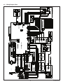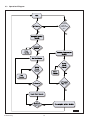
1
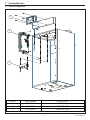
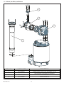
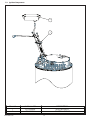
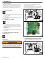
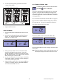
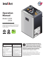
Operation
Manual
Model: i200X
i250X
For units shipped after July 13, 2015
Intellihot Direct Vent Combination Water heater. This
product complies with ANSI Z21.10.3 (2011) / CSA 4.3
Gas Water Heater. For use as potable water heating
and space heating.
if
ox
e
an
k B d to
op
ec rte s z pr
e)
Chnve e Ga au ga
ct
re
ti
di
n
Co pan nver
tio
co
ila
Pro si
la
ca
se
à
nt
ve
né
to
ta
an
n*
st
e)
io
in
an
ers z prop
nv s ga
Co Ga e au
ld nesur plac
Fie pa
n*
roversio
Pon
(C
0
)
0
a
kP
9,0
19 00
.62 a)
(2
,0
.
P
k
20
.C
W
.76 Pa)
.5
. (0 4 k
10
.C
W . (2.7
)
.C
3.0
Pa
W
4k
.0
03
11
)
(1
Pa
si
3k
H)
0p
15 i (10
LP
s
03
p
0
(1
15
H
4
GP
0.9
/
5
26
% 4) m
98 / 0.9 pp
n
io
to % 0
at
er e. et
pqu'à 98 n 2)
Op ur
Uus
a
d ed ion e de
th ppm n anpr
(J
oc at ur
all
n inst océd
ss 20 atiosio
pr
Le de
Co
ch
er
ue
iq
at
m
to
au
S
au
-e
fe
uf
ha
(C
T)
EN
EM
r
H
te
IT
ea SEUL et
W
l)
E
r HRIEUR res nature
US
z
P
ate TÉ
RAVEC
W À L'IN tory Gaposur ga
N
s
IO
FATO
l ine
T
us
ou TION Fac ra
IS
IL
en
SE
neSTALLA
UT
alatu
ge
EUR
Nég
RPO
nta R IN
P
E
. (R
OU
ta
IN
0
.
Y
0
s (P
a)
US
R
D'
In NLY
kP
9,0
. .
S
O
T
GE
19 00
.20 a)
LA
. .
C
ticN O
.
a
ÉG
.
(3
A
,0
.
F ÉR
m TIO
kP
20
. .
.C
PR
. .
W
.
.00 a)
EL
utoLLA
. .
um . .
.0
P
UR
. (2
t ASTA ps
im
13
. .
0k
.C
NAT en
ax
m
IN Am
Z
. .
. . .0 W . (2.0
r M imu
)
GA
t-VOR 5
/h
: .
. . . 8
.C
in
Pa
ec DO Hz, gaz)
W
Btu r M
4k
. . . .
t):
/h
DirR IN , 60
03
e de
8.0
en
.
)
. .
tu
L
RA
TU
NA
GA
lt
yp
(1
m
(T
B
.
se
Pa
FO Vo
si
. .
. .
as
)
as
0
Cl
. . . .
3k
):
0p
12 of G
PH
ts
r le
15 i (10
: . . .
re
en
nt
3L
.
(E
all er l d' la
pe
ure
.
ns
ps
00
st
oi
stm
In nv ue ur
Ty
. .
ss : .
(1
ng
(M
15
ju
to r co mant po
re )
ati
er
))
. . . .
ad
PH
ef l fo au en
.94
ts
s Pimumsure or en
*R ua rer em
tR
/0
. . . .
5G
an
(fstem
Gamax s)
pu
m réfétionn)
% 4)
26
e
In
re
. . . .
um
let ée Pre
(S fonc n.
98 / 0.9 pm
r aju
sio
Ind'arriv asinim ssu
. .
ou
to'à 98 % 20 p
de er
. . . .
m re (p
z
nv
G
m
.
.
p
u ga t ée
R
co
.
n )
U qu
. .
im de le riv s Pimum : . . .
. (Jus thappm
KE
axssion m Inz d'art Géeamin
L)
. .
. .
M
ssde 20
TIC
re
ure . .
ude ga le riv
.
t ET
e
.
s
(P
L oins
.
s
lan
im
n
LS
Inz d'ar
ol
:
io
re
. .
ss
. .
ET (C
. . (M
Min
re
umga
r P) sure
(P
. .
. .
imn de
s
um
. .
ate
t)
inssio
im
r:
W
ric
. .
ax
M
Pre
. .
re
st
to
m
(P
t Di
um u ter )
ac
. .
. .
en
m
im d'ea a imum . t)
yF
.2) ge
. .
axssion m uWmin
: men ergue)
46 na
M
11
re
ud'ea
ngétiq . . .
nguvre E
(P
le ty Ma
: er
im
n
atireco y / én
le
t Ru ali
io
.
in
R
ib
Qu
ss
ric
M
re
st
st Air
ry de nc eur
. .
(P
bu n
t Di t
ve tique ieFact . .
io
en as
m Co
ct ion
cotéris Effiiqcue /
r:
Com
ge th
ru ct
es
na ou
Rearac al er
m
om st trule)
:
be
Ma "S
(C
ncs)
Fr Concons
ib
ns
ty du
m
é th
st
ali .2
um
ara
erm
io
cit
)
'une bu
im
Nu)
r Qu1146
in
Thffica
(D com
iss x)
cm
Cle
m
(E
mde NO ast Aient
adel série
5.2
uments
)
(1
les
ns
Co em
xE
o
eri
m
io
h règl
imagem
ér
om ibles)
c.
ut
Sum
m
iss
6 in
NO
ib
Fr bust
ég
So t au
m
-01
st
(N
Min
(D
(É
5.8
s In
t to en
05
(1
ommbu
)
an ém
gie
in
-Cn-co
)
su rm
L-00
ur fo
m
2 cm
5/8
olo
no
(P on
m
Non
T-LB
5.
n
(c
)
8
es
IG
(1
m
0.
(D
ch
)
m
(5
Te
6 in
m
)
m
0.8
2 in
en
(5
cm
5.8
(1
Gre St. 01 5
2 in
0.4
)
in
(3
)
ot ain 614 70 om
cm
in
au
5/8
-e
llih . M IL 5- 1 ot.c
5.2 m)
12
ffe
(1
te
er
m
at au
In 0 Wurg, ) 83 llih com
)
6 in 2.7
7 te t.
he ch
0
)
au
(1
of du er -e
29 lesb (87 in iho
cm
p s
in
ffe
@ ll
:
Toessu heat au
0.4
1/2
Gaone info nte
)
(3
(D k ofdu ch
.i
in
er au
Ph ail: ww
12
at -e
re
Bac
he auffe
rriè
Emb: w
(A t of ch
e
t
on du
W
Certified to
NSF/ANSI 372
Frvant é)
ne
(A (Côt cabiion)
e
of at
Sid m nalis
to ca
Bot
ôté
(C
WARNING
AVERTISSEMENT
If the information in these instructions is not followed
exactly, a fire or explosion could result causing
property damage, personal injury, or death.
Assurez-vous de bien suivre les instructions données
dans cette notice pour réduire au minimum le
risque d’incendie ou d’explosion ou pour éviter tout
dommage matériel, toute blessure ou la mort.
— Do not store or use gasoline or other flammable
vapors and liquids in the vicinity of this or any
other appliance.
— Ne pas entreposer ni utiliser d’essence ou
ni d’autres vapeurs ou liquides inflammables
à proximité de cet appareil ou de tout autre
appareil.
WHAT TO DO IF YOU SMELL GAS
• Do not try to light any appliance.
• Do not touch any electrical switch; do not use
any phone in your building.
• Immediately call your gas supplier from a
neighbor’s phone. Follow the gas supplier’s
instructions.
• If you cannot reach your gas supplier, call the
fire department.
— Installation and service must be performed by
a qualified installer, service agency, or the gas
supplier.
QUE FAIRE SI VOUS SENTEZ UNE ODEUR DE GAZ
• Ne pas tenter d’allumer d’appareil.
• Ne touchez à aucun interrupteur; ne pas vous
servir des téléphones se trouvant dans
le bâtiment.
• Appelez immédiatement votre fournisseur de gaz
depuis un voisin. Suivez les instructions
du fournisseur.
• Si vous ne pouvez rejoindre le fournisseur,
appelez le service des incendies.
— L’installation et l’entretien doivent être assurés
par un installateur ou un service d’entretien
qualifié ou par le fournisseur de gaz.
To avoid product damage, personal injury, or
even possible death, carefully read, understand,
and follow all the instructions in the Installation
and Operation manuals before installing this
product. Improper installation, adjustment, alteration, or
maintenance can cause injury, loss of life, and/or property
damage. This water heater should be installed and
serviced by a qualified technician. The lack of proper
service can result in a dangerous condition.
This manual contains safety information, installation
instructions, and maintenance procedures. It must be left
with the homeowner or placed near the water heater in
a noncombustible place. The customer should retain this
manual for future reference.
Table of Contents
1. General Information
1.1
1.2
1.3
Items Shipped With Water Heater . . . . . . . . . . . . . . . 4
Contact Information. . . . . . . . . . . . . . . . . . . . . . . . . . . . 4
Serial Number Plate Locations . . . . . . . . . . . . . . . . . . 4
2. Safety
2.1
2.2
Safety Signal Words . . . . . . . . . . . . . . . . . . . . . . . . . . . . 5
Installation Warnings . . . . . . . . . . . . . . . . . . . . . . . . . . . 5
3. Operation
3.1
3.2
3.3
3.4
3.5
3.6
3.7
3.8
3.9
Control Panel . . . . . . . . . . . . . . . . . . . . . . . . . . . . . . . . . . 7
Display Icons. . . . . . . . . . . . . . . . . . . . . . . . . . . . . . . . . . . 7
Turning Water Heater ON and OFF . . . . . . . . . . . . . . 8
Resetting (Clear) Error Codes . . . . . . . . . . . . . . . . . . . 8
Setting the Time . . . . . . . . . . . . . . . . . . . . . . . . . . . . . . . 8
Setting the Domestic Water Temperature . . . . . . . 8
Setting Space Heating Temperature. . . . . . . . . . . . . 9
Real Time Parameter Display. . . . . . . . . . . . . . . . . . . . 9
Error Screen. . . . . . . . . . . . . . . . . . . . . . . . . . . . . . . . . . . 10
4. Programming
4.1
4.2
Modes of Operation . . . . . . . . . . . . . . . . . . . . . . . . . . . 11
Viewing and Setting Modes of Operation . . . . . . 11
5. Maintenance
5.1
5.2
5.3
Cleaning the Inlet Water Strainer. . . . . . . . . . . . . . . 15
Draining the Water Heater . . . . . . . . . . . . . . . . . . . . . 15
Filling the Water Heater . . . . . . . . . . . . . . . . . . . . . . . 16
6. Troubleshooting
6.1
6.2
6.3
Error Code Chart . . . . . . . . . . . . . . . . . . . . . . . . . . . . . . 17
Wiring Diagram Chart . . . . . . . . . . . . . . . . . . . . . . . . . 19
Operational Diagram . . . . . . . . . . . . . . . . . . . . . . . . . . 20
7. Serviceable Parts
7.1
7.2
7.3
7.4
Electrical Components . . . . . . . . . . . . . . . . . . . . . . . . 21
Blower, Gas Valve, and Exhaust. . . . . . . . . . . . . . . . . 22
Water Lines and Fittings . . . . . . . . . . . . . . . . . . . . . . . 23
Ignition Components. . . . . . . . . . . . . . . . . . . . . . . . . . 24
8. Multiple Units
8.1
9.
Modes of Operation . . . . . . . . . . . . . . . . . . . . . . . . . . . 25
Warranty. . . . . . . . . . . . . . . . . . . . . . . . . . . . . . . . . .27
10. Product Warranty Card . . . . . . . . . . . . . . . . . . . . .29
3
Operation
1. General Information
1.1
Items Shipped With Water Heater
1.2
The following items are shipped with the water heater; upper
mounting bracket (1), condensate drain (2), Operation manual
(3), and Installation manual (4).
Contact Information
Call us first if you have any questions about this product. We
can help you with questions about installation or operation,
or if there are damaged or missing parts when you unpack
this unit from the shipping box.
Note: Items 6 through 9 are spare parts shipped with the
unit. Two 10A bus fuses (5), electrode seal (6), O-rings
#015 (7), and 30psi relief valve (8).
7
5
6
1
8
2
SPARES
4
3
Smar
Stamp or write your dealer contact information here for future
reference.
Smar
Ope
Manration
u
Mod al
Inst
Manallatio
n
u
Mod al
el: i2
00
i250X
X
el: i2
00
i250X
X
Intelli
hea hot Dir
ter
(2010) . This ect Ven
ANSIZ / CSAproduct t Boiler/
use 21.10. 4.9 Low complie Comb
as po 3 (20
ina
table 11) Pressures with tion
water/ CSA
Boi ANSI Water
hea 4.3 Ga ler and Z21.13
ting
s
wit and Water h
spa Heate
ce hea r.
ting. For
Intelli
hea hot Dir
ter
(2010) . This ect Ven
ANSIZ / CSAproduct t Boiler/
use 21.10. 4.9 Low complie Comb
as po 3 (20
ina
table 11) Pressures with tion
water/ CSA
Boi ANSI Water
hea 4.3 Ga ler and Z21.13
ting
s
wit and Water h
spa Heate
ce hea r.
ting. For
Due to our policy of continuous product improvement and
technology, the design and/or technical specifications are
subject to change without notice.
Box if
Check
to
Converted
Gas
Propane au gaz propane
Cocher
USE
FORAVEC
UTILISATION
PRESET
POUR
D'USINE
FACTORY
ance s in line
the or other
.
WHA
vicin
T TO
ity of flamm
not
this able
DO
try to
IF YOU
or any
light
SME
any not touch
any
LL
phon
appli
GAS
e in any elect ance
your
.
neighediately
build rical
ing. switc
instrubor’s
call
h;
• Do
• Do
• Imm
do
ction phon your
not
e.
s.
If you
use
Follogas
supp
fire cann
w
the
depa ot reach
lier
gas
from
rtme
your
nt.
supp
— Insta
a
gas
lier’s
llatio
supp
a quali
n
lier,
supp fied and servi
call
the
lier. insta
ller, ce must
servi
be
ce agen
perfo
cy, rmed
or the by
gas
•
non-combustibles)
2 in (50.8
Assu
AV
ER
TISS
dans rez-vous
risque cette de bien
domm d’ince notice suivre
age ndie
pour les
5/8 in
mm)
cm)
(12.7
12 in
(30.4
mm)
cm)
au gaz
propane
directe)
à ventilation
6 in (15.2
mm)
(15.8
6 in (15.2
1/2 in
(15.8
to
Conversion*
Field
Gasau gaz propane)
Propane
sur place
SEULEMENT)
Preset
(Conversion*
199,000
20,000
kPa)
(2.62
W.C.
10.5
kPa)
(0.76
3.0 W.C.
kPa)
(2.74
W.C.
11.0
kPa)
(1034
150 psi
kPa)
(103
15 psi
LPH)
(1003
265 GPH
/ 0.94
98%
Up to 98 % / 0.94)
20 ppm
than
(Jusqu'à
Less 20 ppm)
de
and Operation
(Moins
procedure. et
to Installation
*Refer for conversiond'installation de
la procédure
manual
au manuel
pour
(Se référer
de fonctionnement
conversion.)
STICKER
ETL)
ETL(Collant
cm)
mm)
cm)
6 in (15.2
mm)
2 in (50.8
cm)
(30.4
12 in
Number:
Serial
de série)
(Numéro
Technologies
Green
IntellihotMain St.
W.
IL 61401
2900
1705
835Galesburg,
(877)
Phone: [email protected]
Email:
www.intellihot.com
Web:
Inc.
IGT-LBL-0005-01
EM
EN
T
maté ou
instru
— Ne
riel, d’exp réduire ctions
toute losion au
pas
donn
ni d’aut
bless ou
minim
entre
ées
ure pour
um
à proxi res
pose
ou
éviter le
la mort.
appa mité vape r ni
tout
reil.
de urs ou utiliser
cet
appaliquides d’ess
FAIR
ence
reil
E SI
• Ne
ou inflam
VOU
mablou
de
pas
S SENT
tout
• Ne
tente
es
autre
EZ
servitouchez r d’allu
UNE
mer
r
le bâtim
des à aucu
d’app ODEUR
DE
• Appe ent. télép n interr areil.
GAZ
hone upteu
depu lez immé
s
se r; ne
du is un diate
fourn
trouv pas
• Si
isseu voisi ment votre
ant vous
n.
vous
dans
Suiv fourn
appe ne r.
pouv
ez
lez
isseu
— L’ins
le servi ez
les
r de
rejoin
instr
gaz
par tallation ce des dre
uctio
ns
qualiun insta et l’entr incen le fourn
fié ou llateu etien dies. isseu
r,
par r ou
le fournun doivent
servi
isseu ce être assu
r de d’entretienrés
gaz.
QUE
5/8 in
To avo
eve id pro
n
and possi duct
ble
dama
pro
an follow
de
du
maint ct. Im d Opera all theath, carge, pe
dama enan prope tion instru efullyrsonal
servicge. Thce can r instalmanuals ctions read, injury,
cau
un
or
lation be
in
serviced by is water se inj
for the derst
ury , adjus e ins Instal and,
e can a qu
he
resultalified ater sho, loss of tmen talling lation
t, alt
thi
This
in a techn uld be life, an
era s
dang ician.
d/o tio
ins
instrumanual
ero
The talled r pro n, or
us con
perty
lack
with ctions, contain
an
of prod
dition
a no the ho and mas safety
per
nco meow int
.
manu
mbust ner ena inform
atio
al for
ible or nce
future place.placedproced n, install
atio
refere The near ures.
n
It
the
cus
mu
nce
tom water st be
.
er sho hea
left
ter
uld
retain in
this
If the
exact inform
propely, a ation
fire in these
rty dama
or
ge, explo instru
WA
RN
ING
perso sion ctions
— Do
nal
could is not
not
injury
vapo store
, or resul follow
death t causi ed
otherrs and or use
.
ng
appli liquid gaso
ance s in line
the or other
.
WHA
vicin
T TO
ity of flamm
• Do
not
this able
DO
try
or any
• Do
to light IF YOU
SME
any not touch
any
LL
phon
appli
GAS
e in any elect ance
• Imm
your
.
neighediately
build rical
ing. switc
instrubor’s
call
h; do
ction phon your
not
• If
e.
s.
use
you
Follogas
supp
fire cann
w
the
depa ot reach
lier
gas
from
rtme
your
nt.
supp
— Insta
a
gas
lier’s
llatio
supp
a quali
n
lier,
supp fied and servi
call
the
lier. insta
ller, ce must
servi
be
ce agen
perfo
cy, rmed
or the by
gas
Non-Combustibles
(Des
non-combustibles)
heater
Top of du chauffe-eau)
(Dessus
of heater
Back du chauffe-eau)
(Arrière
of heater
chauffe-eau)
Front
(Avantdu
(Côté)
Side
of cabinet
Bottom
canalisation)
(Côté
EM
5/8 in
6 in (15.2
mm)
2 in (50.8
ER
TISS
5/8 in
mm)
(15.8
6 in (15.2
cm)
1/2 in
(12.7
12 in
(30.4
mm)
cm)
(15.8
to
Conversion*
Field
Gasau gaz propane)
Propane
sur place
SEULEMENT)
Preset
(Conversion*
199,000
20,000
kPa)
(2.62
W.C.
10.5
kPa)
(0.76
3.0 W.C.
kPa)
(2.74
W.C.
11.0
kPa)
(1034
150 psi
kPa)
(103
15 psi
LPH)
(1003
265 GPH
/ 0.94
98%
Up to 98 % / 0.94)
20 ppm
than
(Jusqu'à
Less 20 ppm)
de
and Operation
(Moins
procedure. et
to Installation
*Refer for conversiond'installation de
la procédure
manual
au manuel
pour
(Se référer
de fonctionnement
conversion.)
thermique
.
District)
1146.2)
(Efficacité
Rule
Management
District Quality
Emissions:
Air
NOx
de NOx)
ManagementCoast
"South
(Émissions
Air Quality du
1146.2
Coast
to Southau règlement
Clearances
Combustible
(Pursuant
From
Minimum minimums)
(conformément
Construction
(Dégagements
construction
(D'une
From
combustible)
AV
Assu
dans rez-vous
risque cette de bien
domm d’ince notice suivre
age ndie
pour les
directe)
instantané
automatique
(Chauffe-eau
Heater
À L'INTÉRIEUR
60
. .
199,000
: . .
. . .
120 Volt,
de gaz)
Maximum . . . 20,000
kPa)
of Gas (Type
(3.20
: Btu/hr
W.C.
Minimum
13.0
kPa)
le Classement) Btu/hr
. . .
(2.00
. . .
Rating (Entrer
W.C.
. . .
Input
kPa)
. . 8.0
. . .
(2.00
. . .
W.C.
. . .
Gas Pressure: . . . .
. . 8.0
Inlet maximum)
kPa)
d'arrivée
Maximum
de gaz
psi (1034
Gas Pressure:(for adjustments):
Inlet minimum)
(Pression
. 150
kPa)
. . .
d'arrivée
ajustements))
Minimum
(pour
de gaz
Gas Pressure
. . .
psi (103
Inlet minimum
. . .
(Pression
. 15
. . .
LPH)
d'arrivée
. . .
Minimum
de gaz
(1003
. . .
Pressure:
. . .
(Pression
265 GPH
. . .
Water
. . .
/ 0.94
maximum)
. . .
Maximum
Pressure:
98%
d'eau
. . .
Up to 98 % / 0.94)
Water
(Pression
. . .
. .
. . .
minimum)
(Jusqu'à
. . .
Minimum
20 ppm
d'eau
. . .
. . .
than
(Pression
Less 20 ppm)
Rating:
Factor:
. .
de
(Moins
. . .
:
Recovery de recouvrement)
/ Energy
. . .
(Caractéristique
énergétique)
. . .
Efficiency
/ Facteur
. . .
Thermal
. . .
Type
Non-Combustibles
(Des
heater
Top of du chauffe-eau)
(Dessus
of heater
Back du chauffe-eau)
(Arrière
of heater
chauffe-eau)
Front
(Avantdu
(Côté)
Side
of cabinet
Bottom
canalisation)
(Côté
si converti
instantané
automatique
(Chauffe-eau
Heater
À L'INTÉRIEUR
thermique
.
District)
1146.2)
(Efficacité
Rule
Management
District Quality
Emissions:
Air
NOx
de NOx)
ManagementCoast
(Émissions
Air Quality du "South
1146.2
Coast
to Southau règlement
Clearances
Combustible
(Pursuant
From
Minimum minimums)
(conformément
Construction
(Dégagements
construction
(D'une
From
combustible)
ING
si converti
à ventilation
Water
INSTALLATION Factory
Instantaneous
Gas gaz naturel)
ONLY (POUR
NATUREL
pour
GAZ
Natural
Automatic
en usine
. . . (Réglage
INSTALLATION
. . .
Direct-Vent
Amps
. . .
INDOOR
Hz, 5
. . .
FOR
Propane
Water
.
FOR
60 Hz,
. . .
199,000
: . .
. . .
120 Volt,
de gaz)
Maximum . . . 20,000
kPa)
of Gas (Type
(3.20
: Btu/hr
Type
W.C.
Minimum
13.0
kPa)
le Classement) Btu/hr
. . .
(2.00
. . .
Rating (Entrer
W.C.
. . .
Input
kPa)
. . 8.0
. . .
(2.00
. . .
W.C.
. . .
Gas Pressure: . . . .
. . 8.0
Inlet maximum)
kPa)
d'arrivée
Maximum
de gaz
psi (1034
Gas Pressure:(for adjustments):
Inlet minimum)
(Pression
. 150
kPa)
. . .
d'arrivée
ajustements))
Minimum
(pour
de gaz
Gas Pressure
. . .
psi (103
Inlet minimum
. . .
(Pression
. 15
. . .
LPH)
d'arrivée
. . .
Minimum
de gaz
(1003
. . .
Pressure:
. . .
(Pression
265 GPH
. . .
Water
. . .
/ 0.94
maximum)
. . .
Maximum
Pressure:
98%
d'eau
. . .
Up to98 % / 0.94)
Water
(Pression
. . .
. .
. . .
minimum)
(Jusqu'à
. . .
Minimum
20 ppm
d'eau
. . .
. . .
than
(Pression
Less 20 ppm)
Rating:
Factor:
. .
de
(Moins
. . .
:
Recovery de recouvrement)
/ Energy
. . .
(Caractéristique
énergétique)
. . .
Efficiency
/ Facteur
. . .
Thermal
. . .
RN
la case
WITH
AL GAS
NATUR
INSTALLATION Factory
Instantaneous
Gas gaz naturel)
ONLY (POUR
NATUREL
pour
GAZ
Natural
Automatic
en usine
.
. . . (Réglage
INSTALLATION
. . .
Direct-Vent
INDOOR 5 Amps
. . .
WA
la case
WITH
AL GAS
NATUR
PRÉRÉGLAGES
Box if
Check
to
Converted
Gas
Cocher
USE
FORAVEC
UTILISATION
PRESET
POUR
D'USINE
FACTORY
PRÉRÉGLAGES
If the
exact inform
propely, a ation
fire in
rty
dama or these
ge, explo instru
perso sion ctions
— Do
nal
could is not
not
injury
vapo store
, or resul follow
death t causi ed
otherrs and or use
.
ng
appli liquid gaso
STICKER
ETL)
ETL(Collant
cm)
mm)
cm)
6 in (15.2
mm)
2 in (50.8
cm)
(30.4
12 in
Number:
Serial
de série)
(Numéro
Technologies
Green
IntellihotMain St.
W.
IL 61401
2900
1705
835Galesburg,
(877)
Phone: [email protected]
Email:
www.intellihot.com
Web:
Inc.
IGT-LBL-0005-01
EN
T
maté ou
instru
— Ne
riel, d’exp réduire ctions
toute losion au
pas
donn
ni d’aut
bless ou
minim
entre
ées
ure pour
um
à proxi res
pose
ou
éviter le
la mort.
appa mité vape r ni
tout
reil.
de urs ou utiliser
cet
QUE
appaliquides d’ess
FAIR
ence
reil
E SI
• Ne
ou inflam
VOU
mablou
de
pas
S SENT
tout
• Ne
tente
es
autre
EZ
servitouchez r d’allu
UNE
mer
r
le bâtim
des à aucu
d’app ODEUR
DE
• Appe ent. télép n interr areil.
GAZ
hone upteu
depu lez immé
s
se r; ne
du is un diate
trouv pas
fourn
• Si
isseu voisi ment votre
ant vous
n.
vous
dans
Suiv fourn
appe ne r.
pouv
ez
lez
isseu
— L’ins
le servi ez
les
r
rejoin
instr de gaz
par tallation ce des dre
uctio
ns
qualiun insta et l’entr incen le fourn
fié ou llateu etien dies. isseu
r,
par r ou
le fournun doivent
servi
être
isseu ce
assu
r de d’entretien
rés
gaz.
To avo
eve id pro
n
and possi duct
ble
dama
pro
an follow
de
du
maint ct. Im d Opera all theath, carge, pe
dama enan prope tion instru efullyrsonal
servicge. Thce can r instalmanuals ctions read, injury,
cau
un
or
lation be
in
serviced by is water se inj
for the derst
ury , adjus e ins Instal and,
e can a qu
he
resultalified ater sho, loss of tmen talling lation
This
in a techn uld be life, t, altera this
dang ician.
ins and/o tio
instrumanual
ero
The talled r pro n, or
us con
lack
perty
with ctions, contain
an
of prod
dition
a no the ho and mas safety
per
.
nco meow int
info
manu
mb
ena
rm
al for ustiblener or nce pro ation,
future place.placed ced install
refere The near ures. It ation
nce customthe wa must
.
er shoter hea be left
ter
uld
retain in
this
Serial Number: ___________________________________
Date of Installation: ___ / ___ / ______
IQ-007-250X
1.3
WARNING
Serial Number Plate Locations
Each unit’s heat exchanger module has its own ASME
certification plate (1). Rating plate (2) contains serial number
for the unit. Please provide this serial number when calling
for service or warranty.
Condensate drain line (2) is shipped from the factory with a
loop held together with plastic ties. Do not remove the ties
and/or straighten the loop. This loop forms an air block
(trap) which prevents carbon monoxide from exiting the
water heater through the drain line. Improper installation of
the drain line can result in excessive levels of carbon
monoxide, which can lead to severe personal injury or death.
1.1.1 Optional Items
x if
e
pan
k Bo to
pro
ec ed s
)
Chnverte Ga au gaz
cte
i
dire
Co an vert
tion
op con
tila
Pr e si
la
cas
à
ven
é
to
her
tan
tan
n*
)
ins
ane
sio
ue
prop
er
nv s gaz
Co Ga e au
d
plac
el anesur
Fi
oprsion*
Prnve
00
a)
kP
9,0
62
0
a)
(2.
,00
kP
C.
20
W.
76
a)
.5
(0.
kP
10
C.
74
W.
(2.
C.
a)
3.0
W.
kP
.0
34
11
a)
i (10
kP
H)
0 ps 3
15 i (10
LP
03
ps
(10
15
H
4
/ 0.9
5 GP
26
% ) m
98 / 0.94 pp
n
to 98 % 20
ratio
n )
Ope ure.n et de
Upqu'à
thappm and cedlatio ure
(Jus
ss 20 tionion prostal céd
Le de
Coc
atiq
om
aut
au
fe-e
S
GA
H
IT
E
US
C
W
auf
(Ch )
er ENT
at LEM
He R SEU et rel)
erTÉRIEU Pres natu
at
s r gaz
RAVE
W À L'IN or y Gapou
N
s
FO
l e
TIO
usin
ou ION Fact ra
ETLISA
tue en
ne LAT
ESR UTI
Na
glag
ta INSTAL
POU
(Ré
PR
E
an UR
. .
Y SIN
00
st (PO
a)
D'U
In LY
kP
9,0
. .
OR
ES
19 0
ic ON
20
LAG
. .
CT
.
at N
a)
(3.
,00
FARÉG
. .
m
kP
C.
20
. .
PRÉ
to LATIO
L
W.
.
. .
00
RE
um . .
.0
(2. kPa)
. .
TU
t Au ALps
13
C.
xim
NA
. .
.
en INST
W. (2.00
Z
um
Am . .
-V
r Ma
. .
GA
a)
8.0
C.
ct OR , 5
) :
u/h Minim . .
kP
W.
re DO Hz
gaz
. .
r
.
: Bt
34
Di R IN 60
e de
8.0
u/h
ent)
. .
. .
TU
NA
Ra
(Catin
racg an
téri d
stiq sa
ues fet
et y
ren
inf
sei
or
gnema
me tio
nts n ins
de
sécide
urit .
éà
l'in
téri
eur
)
lt,
a)
.
Bt
i (10
sem
FO Vo
. .
s (Typ
. . . .
kP
0
:
Clas
H)
0 ps 3
le
12 of Ga
. . . .
ts)
15 i (10
LP
trer
en
re: . .
.
d'in pro
(En
03
alla
pe
ps
tm
ins
versuel r la
su
g
.
Ty
. .
(10
(Mo to Inst
15
con
es
jus
tin
pou
H
4
m)
fer for au man
. . . .
re: r ad ))
ent
Ra
s Pr
imu su
*Re ual rer
ents
/ 0.9
nem
ut
. . . .
5 GP
(fo
Gamax es
manréfétion )
tem
% ) m
26
Inp
etrivée Pr m) re
. . . .
(Sefonc ion.
98 / 0.94
s imu su r ajus . .
Inl
. .
to 98 % 20 pp
d'ar
de vers
(pou
. .
e min es
umgaz et Ga
R
m
con
. .
Upqu'à n )
. . . .
imu
s Pr
KE
ppm
ximn de Inld'arrivé
. .
)
. . (Jus tha
Ga
IC
ssio
re: . . .
e min
Ma
ssde 20
gaz et
um
. .
t ETL
. .
su
rivé
(Pre
de
Leins
llan
L ST
es
nimn Inld'ar
. .
. .
Pr
re:
ET (Co
. . (Mo
Mi ssio umgaz
. .
. .
de
(Pre
term) essu
n
. .
nim
. .
imu
r:
ssio
Wa
rict)
Mi
Pr
. .
max
. .
(Pre
cto
t Dist
umu ter m)
. .
. t).
imu
men
y )Fa
ximn d'eaWa
. .
6.2) age
min
ssio
u
Ma
g: men erg
ique
um
. .
e 114 Man
(Pre
uvre :
d'ea
tin
En
.
rgét
lity
n
Rul
/
nim
Ra reco y éne . .
ible
ssio
rict Qua
Mi
ry e de ncteur
Air
ust
.
(Pre
t Dist
st
ve tiqu cie/ Fac . .
mb tionn
men Coa
fi ue
co éris
r:
Co ruc ctio
s
age uth
m
Re ract al Efmiq
ce
be
stru )
Man "So
(Ca
s:
FroConst
ther
con tible
m
ranms)
lity du
ermité
ion
ne
)
bus
6.2
ea
Th icac issNOx) Air Qua
(D'ucom
e)
114
cm
Clminimu
l Nu
(Eff
nt
.2
st
de
um nts
riade séri
(15
)
les
Coa eme
x Em
ons
.
s)
Seméro
mm
nim eme From stib
6 in
NOissi Southau règl
Inc
.8
-01
bu tible
(Nu
Mi(Dégag
(Ém
to nt
(15
nt éme
om bus
ies
005
)
in
)
L-0
rsua
cm
n-C -com
log
form
5/8
-LB
.2
(Pu
mm
Nos non
no
)
(con
IGT
.8
(15
(De
ch
)
mm
(50
Te
6 in
.8
)
mm
n
2 in
(50
.8
cm
ee . 1
.4
(15
2 in
)
t Grin St 40 05 om
in
(30
u)
cm
61 17
in
5/8
iho Ma
.2
-ea
)
t.c
12
IL 5ell
(15 mm
ter uffe
Int W. rg, 83elliho om
.7
6 in
u)
7)
hea cha
00
t.c
(12 cm)
-ea
of du
29 lesbu(87 int iho
p s
in
ter
.4
To ssu hea uffe
ell
1/2
Gaone: info@
(30
u)
int
(De ofdu cha
in
ter -ea
ck e
Ph ail: w.
12
Ba rièr hea uffe
Emb: ww
(Ar of cha
nt du
t
We
Froant té)
ine
(Av (Cô cab n)
e
of atio
Sid m alis
tto can
Bo té
(Cô
1
An optional outdoor sensor can be purchased separately
connected to this unit (part number: IGT-SPR0074).
General Information
4
L
RA
(Co
19
2
2. Safety
2.1
DANGER
Safety Signal Words
DANGER
Indicates an imminently hazardous situation which, if not
avoided, will result in death or serious injury. This signal
word is limited to the most extreme situations.
WARNING
Indicates a potentially hazardous situation which, if not
avoided, could result in death or serious injury.
CAUTION
Indicates a potentially hazardous situation which, if not
avoided, may result in minor or moderate injury.
NOTICE
Indicates that equipment or property damage can result if
instructions are not followed.
SAFETY
INSTRUCTIONS
Safety instructions (or equivalent) signs indicate specific
safety-related instructions or procedures.
B. BEFORE OPERATING, smell all around the water heater
area for gas. Be sure to smell next to the floor because
some gas is heavier than air and will settle on the floor.
WHAT TO DO IF YOU SMELL GAS:
• Do not try to light any appliance.
• Do not touch any electric switch; do not use any phone in
your building.
• Immediately call your gas supplier from a neighbor’s
phone. Follow the gas supplier’s instructions.
• If you cannot reach your gas supplier, call the fire or
police department.
C. Use only your hand to turn the manual gas shut-off
valve. Never use tools. If manual gas shut-off valve will
not turn by hand, don’t try to repair it. Call a qualified
service technician. Force or attempted repair may
result in a fire or explosion.
WARNING
DO NOT use or store flammable liquids around the water
heater, including gasoline, oils, spray paints, etc.
DO NOT operate this water heater unless it is properly
vented to the outside (the exhaust vent piping must be
connected from the unit directly to the outside). Improper
venting can cause a build-up of carbon monoxide, which
can result in brain damage or death. Exhaust gases must
be completely expelled out of the building.
This water heater is factory preset for NATURAL GAS but
may be field converted for use with propane. For propane
conversion, refer to the Propane (LPG) Conversion section
of this manual. Connecting the water heater to any other
gas supply can result in property damage, serious injury,
or even death.
Note: Contains additional information important to a
procedure.
2.2
A. This water heater does not have a pilot. It is equipped
with an ignition device which automatically lights the
burner. Do not try to light the burner manually.
Installation Warnings
WARNING
DO NOT use this water heater for any purpose other than
water heating.
Read, understand, and follow the Installation and Operation
manuals, including all warnings and precautions, before
operating this water heater. If you do not follow these
instructions exactly, a fire or explosion may result, causing
property damage, personal injury, or loss of life.
Follow all local codes and the most recent edition of the
National Fuel Gas Code (ANSI Z223.1/NFPA 54) in the USA or
the Natural Gas and Propane Installation Code in Canada
(CSA B149.1).
This water heater is suitable for use in potable water
heating applications. The cold and hot water fittings on
the top of the water heater MUST NOT be connected to any
heating system.
The water heater temperature is factory set to 120°F
(49°C). Hot water temperatures above 125°F can cause
severe burns instantly or death from scalds. If the
proposed water heater outlet temperature is to be set
above 125°F, installation of a thermostatically controlled
(or temperature limiting) mixing valve is recommended for
all hot water going to faucets to avoid the risk of scalding.
Examples include commercial applications where 140°F
(60°C) is often needed or if the space heating temperature
required is higher than the domestic hot water. Always
check the temperature of the hot water before bathing,
showering, washing, etc.
Protect against snow and debris accumulation around the
vent terminations. Regularly inspect the exhaust vent
pipe and the air intake pipe to ensure they remain clear
from obstructions at all times.
This water heater must be installed by a licensed plumber,
gas fitter, and/or professional service technician. Installation
by unqualified person(s) voids the warranty.
5
Safety Section
CAUTION
Make sure you know the location of the gas shut-off valve
and how to operate it. Immediately close the gas shut-off
valve if the water heater is subjected to fire, overheating,
flood, physical damage, or any other damaging condition
that might affect the operation of the unit. Have the water
heater checked by a qualified technician before resuming
operation.
If the water quality is known to have high acidity and/or
high hardness, water treatment is recommended. Consult
the local water authority.
SAFETY
INSTRUCTIONS
DO NOT use this appliance if any part has been under
water.
DO NOT reverse the cold water and gas connections as this
will damage the gas valve.
DO NOT overtighten fittings as damage may occur, causing
internal leakage.
The appliance should be located in an area where leakage
within the unit or at its connections will not result in
damage to the surrounding area. The manufacturer will
not be responsible for any damage resulting from leaking
if adequate drainage is not provided.
WARNING
All piping and components connected to the water heater
for the space heating application shall be suitable for use
with potable water.
Do not use toxic chemicals, such as used for boiler
treatment, in potable water, in potable water heating
systems.
Suitable for water (potable) heating and space heating.
the water heater MUST NOT be connected to any heating
system or components previously used with a nonpotable water heating appliance.
If the system requires water for space heating at
temperatures higher than required for other uses, a
mixing valve must be installed to temper the water for
those other uses in order to reduce scald and hazard
potential.
Water heaters used for combination water/space heating
CANNOT be used in space heating applications only.
Safety Section
6
3. Operation
3.1
A) LCD screen
The LCD display screen shows all information about the
operating functions of the water heater.
Control Panel
A
G
B) Arrow keys
Press the UP or DOWN arrows to adjust the value of the
selected feature, such as time or water temperature.
C) Enter button
To return to the Main or Home screen.
F
B
D) Power button
When the water heater is initially connected to an electrical
power supply, the unit will automatically turn ON and the
display panel should light up. To turn the unit OFF, press
and hold the Power button and the water heater will go
through a shutdown process. The unit can then be turned
ON again, once the blower finishes its purge cycle (10
seconds) by pressing the Power button.
Mode
Time
E
Enter
Power
D
C
E) Time button
Press this button to set the hours and minutes on the clock.
F) Mode button
Press this button to access various Modes of Operation.
G) Orange button
Used to view real time flow and temperature readings.
3.2
Display Icons
H) Displays the current time in AM or PM.
I)
K
T
S
L
M
N
O
CODE Display
Displays the CODE icon and the most recent digital error
code.
K) Error Icon
Indicates an error has been detected and a trouble code
may be shown next to the CODE icon.
L) Indicates water flow (open faucet).
I
P
M) Indicates blower is ON.
N) Indicates burner is ON.
H
O) Gas Consumption Icon
Indicates the level of energy usage. There are four “bar”
indicators and each represent 25% of gas usage.
P) Indicates outlet water temperature.
S) Freeze Indicator Icon
This icon indicates that the unit has detected potential
freezing conditions and will operate to keep the internal
component water temperature above the freezing limits.
T) Thermostat Icon
Indicates the unit has received a signal from the
thermostat calling for heat.
7
Operation
3.3
4. Press the Up/Down arrows to set the correct hour. When
setting the hour, make sure you have correctly advanced
the time to either the AM or PM hour setting.
Turning Water Heater ON and OFF
1. When plugging in, the unit will show the four digit
software version. To turn the water heater ON press the
Power button. The screen will show INIT until initialized,
and the home screen will automatically display when the
unit is ready to use.
2. To turn the water heater OFF, press and hold the Power
button for three seconds and the display screen will show
OFF.
3.4
Resetting (Clear) Error Codes
5. Press and release the Time button again.
1. To reset the water heater and clear all error codes, press
and release Power button.
3.5
The colon (:) between the hours and minutes should now
be flashing, indicating the time has been properly set.
Setting the Time
1. Press and release the Time button.
The minute section of the time display will flash.
3.6
Setting the Domestic Water Temperature
Note: The outlet water temperature is factory preset to 120°F.
WARNING
Hot water temperature over 125°F (52°C)
can cause severe burns instantly or death
from scalding. Children, the disabled, and
the elderly are at the highest risk of being
scalded. Do not leave children or the infirm
unsupervised. Check temperature of hot
water before taking a shower or bath. To
control water temperature to a particular faucet,
temperature limiting valves can be installed by your
service professional.
2. Press the Up/Down arrows to set the correct minute.
All water faucets must be closed before changing the
temperature setting. The unit must not be operating
(burner icon not on).
3. Press and release the Time button again.
Press the Up/Down arrows to set the desired temperature
range from 100 to 140°F in one degree increments.
The hour section of the time display will flash.
Operation
8
3.7
Actual Outside Air Temperature (if connected)
toAt and the actual outside air temperature, such as 65°F.
Setting Space Heating Temperature
Press and hold the Orange button. On the right-hand side
of the display the current temperature setting of the supply
water is shown. To change the supply water temperature
push the Up/Down arrow key, while continuing to hold the
orange button. The setting range for the supply water is
from 100°F to 170°F. However, the minimum space heating
set temperature is 20°F below the domestic hot water set
temperature.
3.8
If -- is shown, this parameter is unavailable or sensor is not
connected..
Real Time Parameter Display
Press and release the Orange button. The left-hand side
of the display scrolls through the following parameters in
succession: After scrolling through the parameters three
times, the display returns to the main screen.
Domestic Outlet Water Temperature
tout and the actual domestic hot water (DHW) outlet
temperature, such as 120°F
Flow Rate
The flow rate is indicated with FlO and actual flow rate
(3.5 GPM).
Heat Exchanger Temperature
tHE and the actual temperature of the heat exchanger, such
as 120°F.
9
Operation
Recirculation Temperature
trEC and the actual temperature of recirculation, such as 110°F.
Flue Temperature
FLUE and the actual temperature of flue, such as 110°F.
3.9
Error Screen
If an error occurs, the display will indicate an error code; E1, E3,
E7, etc. The flashing triangle will also appear in the upper left
corner of the display to indicate a potential problem with the
unit.
Refer to the Troubleshooting section for additional
information on the resolution of error codes.
Operation
10
4. Programming
4.1
The water control valve is set to ON for temperature priority
and OFF for maximum flow.
Modes of Operation
The Modes of Operation screens provide set up screens and
additional information on the water heater. There are five
Mode of Operation screens which are used by the technician
during installation or maintenance of the water heater.
4.1.1
Press the Up/Down arrows to select either ON or OFF.
Standard Modes
1. Press and release the Mode button until the desired screen
shows on the display.
FC - Flow Control
PH - Performance History
IH - Setting Instant Hot Water Times
dE - Diagnostic Error
Press and hold the Enter button for three seconds to save the
settings and return to the home screen.
Note: If the Enter button is not pressed within 30 seconds of
inactivity, the display will return to the home screen.
2. Follow the instructions in the specific section to enter the
desired settings.
4.1.2
Advanced Modes
1. Press and hold the Mode button for five seconds until
the rS screen appears. Now press and release the Mode
button multiple times until the desired screen shows on
the display.
rS - Burner Rate Ramp Setting
Ft - Fuel Type
FP - Flue Pipe Type
CO - Adjust CO2 Level
2. Follow the instructions in the specific section to enter the
desired settings.
4.2
4.2.1
Viewing and Setting Modes of Operation
Flow Control Selection
Press the Mode button multiple times until the
FC screen appears on the display.
The current setting will be shown on the display.
11
Programming
4.2.2
Performance History
4.2.3
The Performance History mode allows the
technician to view ignition cycles, number of ON
times, and cumulative water flow. The displayed
results are for all the water heater modules
combined within the unit.
Setting Instant Hot Water Times
This mode is used to set the times when the unit
will supply instant hot water.
This mode can only be accessed when Flame icon is
NOT showing on the display.
Press the Mode button multiple times until the PH screen
appears.
The Flow-On Hours FH, Firing Counts FC, and Cumulative
Flow CF, will now begin to display for 1.5 seconds each. The
display will continue to cycle for 30 seconds and then return
to the home screen. Some examples are shown below.
Push Mode button multiple times until IH appears on the
display.
Diagnostic Code FH (Flow-on hours)
shows one hour of flame. (To obtain
the total hours, multiply the number
by 10).
The current setting will show in the time area of the display as
Auto, 24-7, Pat1, Pat2, Pat3, Pat4, or nonE.
Diagnostic Code FC (Firing Count)
shows a flame count of 40,000. (To
obt ain the total number, multiply
the number by 1,000).
The default setting is AUtO and the learned times will be
displayed.
Diagnostic Code CF (Cumulative
Flow) shows 38,000 gallons of
water. (To obtain the usage in
gallons, multiply the number by
1,000).
Press the Up/Down arrows to toggle between the available
six patterns (Auto, 24-7, Pat1, Pat2, Pat3, Pat4, or nonE).
Once the desired pattern is selected, press and hold the Enter
button for three seconds to save the settings and return to
the home screen.
Press and hold the Enter button for three seconds to return to
the home screen.
If the Enter button is not pressed within the 30 second time
limit, the setting will not be saved.
Note: If the Enter button is not pressed within 30 seconds of
inactivity, the display will return to the home screen.
Programming
12
4.2.4
Diagnostic Code and Error Log Selection
4.2.5
Blower Ramp Selection
This screen provides the technician with Diagnostic
Codes and Errors recorded as the water heater
operates. These codes are used in conjunction with
the Performance History Codes.
When exhaust harmonics are observed, i.e.
resonance at low fire, adjust the water heater using
the blower ramp setting (default is rat3). Increase
the rate number until the resonance is no longer
observed.
Error Code
Description of Error Code
E1
Blower Speed Fault
E3
Blocked Flue Fault
E7
Ignition Failure
E9
Temperature Sensor Shorted
EA
Temperature Sensor Open Circuit
EC
Flue Temperature Exceeded Set Limit
Ed
Heat Exchanger Outlet Temperature Exceeded
Set Limit
Flashing
Warning Icon
Error Code and Unit Locked Out
Flashing
Recirculation
Icon
Pump Is Not Operating
The Blower Ramp Selection has five different settings
(rat1 - rat5):
Press and hold the Mode button for five seconds to access
the rS screen on the display. The current setting will be
displayed.
Press the Up/Down arrows to select the Blower Ramp
Selection from five different settings (rat1 - rat5).
Select a ramp rate at which the harmonics disappears during
operation.
* If Eb is displayed, please call the factory for service instructions.
Press and release the Mode button multiple times until the
dE screen appears.
The 01:E1 screen is the most recent code, while the 10:E3
is the last viewable screen. Refer the examples below for
further clarification.
Example of latest diagnostic code
Fan Speed Error Code E1.
Press and hold the Enter button for three seconds to save the
settings and return to the home screen.
Note: If the Enter button is not pressed within 30 seconds of
inactivity, the display will return to the home screen.
Example of the last viewable code
Blocked Flue Fault Code E3.
Press and hold the Enter button for three seconds to return to
the home screen.
Note: If the Enter button is not pressed within 30 seconds of
inactivity, the display will return to the home screen.
13
Programming
4.2.6
Fuel Type Verification
4.2.7
The Fuel Type mode screen shows the selected fuel
type; natural gas (factory preset) or Propane.
Operation with natural gas is factory preset. Refer
to the Propane (LPG) Conversion section in this
manual for additional set up information.
Flue Pipe Selection (PVC or CPVC)
Changing this setting can only be done when the
Flame ON
icon is not displayed.
WARNING
Press and hold the Mode button for five seconds to access the
rS screen on the display.
When the unit is set for CPVC or polypropylene pipe,
flue temperatures can reach 185°F. PVC pipe will
lose integrity at temperatures above 149°F. Make
sure FP setting and the type of material being used for the
flue are compatible.
Press and hold the Mode button until the rS screen appears.
Press the Mode button multiple times until the FP screen
appears. The current setting will be displayed.
Press and release the Mode button until the Ft screen appears
on the display. The current Fuel Type setting will appear (nAt
or PrOP) to indicate the position of DIP switch 3 on the circuit
boards. Fuel type cannot be changed from the screen.
The default setting for this mode is PVC.
Press the Up/Down arrows to select the desired setting of
either PUC or CPUC.
To change fuel type from factory set natural gas to propane,
follow the Propane Conversion procedure in this manual.
Note: The flue temperature for PVC material must not
exceed 149°F. The flue temperature for CPVC or
Polypropylene material must not exceed 185°F.
Press and hold the Enter button for three seconds to return to
the home screen.
Note: If the Enter button is not pressed within 30 seconds of
inactivity, the display will return to the home screen.
Press the Enter button to save the changes and return to the
main screen.
Note: If the Enter button is not pressed within 30 seconds of
inactivity, the display will return to the home screen.
4.2.8
Adjusting CO2 Levels Selection
Refer to the Adjusting the CO2 Level section in this
manual.
Programming
14
5. Maintenance
5.1
Cleaning the Inlet Water Strainer
5.2
Draining the Water Heater
All the water heaters are equipped with a sediment strainer
on the inlet water connection.
CAUTION
Initially, this strainer should be inspected and cleaned every
three months to establish a cleaning schedule.
Hot water can cause burns to the skin. The water
temperature is factory set to 120°F (49°C). To avoid burns,
make sure the water heater is OFF and the power supply is
disconnected. The water heater will remain hot for some
time. Wait until the unit has completely cooled before
draining the water heater or performing any other
maintenance.
1. Press the Power button to turn OFF the water heater.
Disconnect the power.
2. Close the water supply inlet and outlet valves. Turn OFF
the gas supply.
IH-162
1. Turn off power and gas.
2. Position a container under the strainer on the water inlet
piping.
3. Close the water inlet and outlet valve (arrow) and remove
the cover plug. Allow the water to drain from the pipe.
IQ-046
3. Position a bucket or other container against the drain port.
4. Use an Allen wrench and remove drain plug (1).
IQ-045
Note: If a water shut-off valve was not installed, shut off the
main water supply valve at the water heater.
4. Remove the strainer screen, clean it, and reinstall it in the
housing.
1
IQ-111
5. When all the water has drained from the water heater,
replace the drain plug.
IH-162a
5. Replace the strainer cover plug.
15
Maintenance Section
5.3
Filling the Water Heater
1. Open the water outlet supply valve. Slowly open the water
inlet supply valve.
2. Open the hot water faucet that is located farthest away
from the water heater. Once a steady stream of water
flows and all the air is purged from the system, close the
hot water faucet.
3. Connect the unit to the power supply.
4. Open a hot water faucet. The water heater should operate
normally.
Maintenance Section
16
6. Troubleshooting
6.1
Error Code Chart
Blower Speed Fault
• Blower noisy / impeller jammed.
• Disconnected signal wire.
• Inspect blower / impeller. Clean and remove any
obstructions.
• Check PWN signal. Check for loose wires / pins, and
repair.
• Check PWN signal. Check for loose wires / pins, and
repair.
• Wiring faulty.
If the problem persists, turn control panel OFF, shut gas
valve, unplug unit, and contact an authorized service
technician.
Blocked Flue Fault
Ignition Failure
• Exhaust blocked (bird, etc).
• Check exhaust termination. Check exhaust
connection at water heater. Install screens.
• Backed up condensate.
• Check slope of drain. Check for double loops, air
locks, or debris in loop.
• Wiring loose (switch open).
• Check wiring.
• Water over-heat switch tripped.
• Check pump, check cross over solenoid. Electrical
noise (dsi).
• Faulty DSI, faulty igniter wire,
faulty ignition connection, faulty
PCB, bad igniter.
• Low gas pressure.
• Replace part.
• Adjust gas pressure at regulator, check / upsize gas
line, check for gas line blockage.
• If the problem persists, turn control panel OFF, shut
gas valve, unplug unit, and contact an authorized
service technician.
Temperature Sensor
Shorted
• Faulty sensor wiring
• Check for nicked or broken sensor wiring or
connectors. Also check for corroded or wet
connectors.
• Faulty sensor
• Measure resistance of sensor at connector (18 Kohm
at 50°F, 10 Kohm at 77°F, 3 Kohm at 140°F)
• HE - heat exchanger water outlet
temperature sensor.
• FL - Flue temperature sensor.
• OA - outdoor air temperature
sensor.
• Faulty controller
• Replace controller
• rE - Recirculation temperature
sensor.
• Ou - Domestic Hot water outlet
temperature sensor.
17
Troubleshooting
Temperature Sensor
Open Circuit
• Unplugged connectors
• Check connectors and ensure they are securely
connected
• Faulty sensor wiring
• Check for nicked or broken sensor wiring or
connectors. Also check for corroded or wet
connectors
• Faulty sensor
• Measure resistance of sensor at connector (18 Kohm
at 50°F, 10 Kohm at 77°F, 3 Kohm at 140°F)
• HE - heat exchanger water outlet
temperature sensor.
• FL - Flue temperature sensor.
• Faulty Controller
• rE - Recirculation temperature
sensor.
• Replace controller
• Ou - Domestic Hot water outlet
temperature sensor.
Flue Temperature
Exceeded Set Limit
Heat Exchanger Outlet
Temperature Exceeded
Set Limit
Troubleshooting
• Incorrect vent set up
• If vent pipe material is CPVC or Polypropylene, ensure
that CPVC is selected in the FP (Flue Pipe) mode.
• High inlet temperature
• Ensure inlet temperature is lower than 150°F if vent
pipe material is PVC or lower than 190°F if vent pipe
material is CPVC or Polypropylene.
• Faulty sensor wiring
• Check for nicked or broken sensor wiring &
connectors. Also check for corroded or wet
connectors
• Faulty sensor
• Measure resistance of sensor at connector (18 Kohm
at 50°F, 10 Kohm at 77°F, 3 Kohm at 140°F)
• Faulty Controller
• Replace controller
• Flow rate changes excessive
• Ensure the water flow rate does not change faster
than 2 GPM every 5 seconds
• Faulty sensor wiring
• Check for nicked or broken sensor wiring or
connectors. Also check for corroded or wet
connectors
• Faulty sensor
• Measure resistance of sensor at connector (18 Kohm
at 50°F, 10 Kohm at 77°F, 3 Kohm at 140°F)
• Faulty Controller
• Replace controller
Flashing Icon
• Indicates an error code and unit
locked out
• Refer to the indicated error code (E1, E2, etc) for
resolution
Recirculation Icon
Flashing
• Pump inoperable
• Check pump wiring harness for loose connectors
• Pump faulty & excessively hot
• Replace pump
• Faulty Controller
• Replace controller
• Plugged up solenoid valve
(P models)
• Clean lines and replace solenoid
• Solenoid valve faulty (P models)
• Replace solenoid valve
• Jammed check valve
• Remove check valve access and ensure gate is free to
move
Init stays on display
• Faulty time valve/wiring
• Replace time valve/wiring
Heat Exchanger never
reaches set temperature
• Solenoid valve faulty
• Check solenoid (SMC) valve and replace if necessary
18
BLOWER
19
ONLY
BN
F
THERMAL
FUSE
RD
WT
BL
LINE
HEATING SYSTEM GROUND
PUMP TERMINAL
NEUTRAL
PUMP
3-cord cable
BL
F
THERMAL
FUSE
TRANSFORMER
BN
WT
BN
BN
RD
RD
BN
RD
BN
HIGH VOLTAGE CABLE
GAS
VALVE
BN
BL
ON
WT
GN
OR
WT
IGNTER AND FLAME PROBE
OUTLET TEMP
OUTLET TEMP
FLUE TEMP
GY
BYBASS
SOLENOID
VALVE
TEMPERATURE
SENSORS
OFF
LP
NG
GREEN LED
(POWER)
FUEL SELECT
RED LED
(BURNER ON)
FUSE
FUSE
WT
BL
GY
OR
OFF
GN
YL
RD
RD
GN
RD
RD
BL
BN
GN
GY
OR
RD
WT
YL
BLUE
BROWN
GREEN
GRAY
ORANGE
RED
WHITE
YELLOW
WIRE COLOR CODE
OUTDOOR TEMPERATURE SENSOR
WT
ON
CASCADING
CONNECTIONS
BOILER TT
YL
BL
BL
BL
WT
BN
WATER CONTROL VALVE
AND FLOW SENSOR
COLD WATER
INLET TEMP
OR
GN
AIR SWITCH
6.2
Wiring Diagram Chart
Troubleshooting
6.3
Operational Diagram
Is
Program
time or
Thermostat
On?
?
?
?
?
?
?
?
IH-156
Troubleshooting
20
7. Serviceable Parts
7.1
Electrical Components
1
2
3
ITEM NO.
PART NUMBER
1
2
3
IGT-SPR0004
IGT-SPR0002
IGT-SPR0005
DESCRIPTION
DISPLAY
CONTROLLER
IGNITER MODULE
21
Serviceable Parts
7.2
Blower, Gas Valve, and Exhaust
2
4
3
1
ITEM NO.
1
2
3
4
Serviceable Parts
DESCRIPTION
i20;/i250; FLUE PIPE ASSEMBLY (PP)
L;L;GAS INLET ASSEMBLY
BLOWER KIT
GAS VALVE KIT
PART NUMBER
IGT-SPR0017
IGT-SPR0016
IGT-SPR0008
IGT-SPR0011
22
7.3
Water Lines and Fittings
2
4
15
5
3
12
21
1
16
13
1
11
7
21
18
6
14
19
8
20
9
17
10
1
DESCRIPTION
ITEM NO.
PART NUMBER
1
IGT-SPR0036
SMALL TEE
2
IGT-SPR0018
WATER INLET FITTING (3/4" NPT)
HEAT EXCHANGER INLET TOP TUBE
3
IGT-SPR0024
4
IGT-SPR0023
BY PASS TUBE
5
IGT-SPR0003
FLOW SENSOR KIT
6
IGT-SPR0025
HEAT EXCHANGER INLET BOTTOM TUBE
7
IGT-SPR0026
HEAT EXTANGER OUTLET TOP TUBE BUFFER
8
IGT-SPR0028
TANK TO DRAIN PORT TUBE
9
IGT-SPR0027
HEAT EXCHANGER OUTLET BOTTOM TUBE
10
IGT-SPR0029
DRAIN PORT
11
IGT-SPR0031
TEE BY-PASS LINE 2
12
IGT-SPR0032
PUMP TEE TO WATER OUT TUBE ASSEMBLY
PLATE HEAT EXCHANGER OUT TUBE
13
IGT-SPR0033
14
IGT-SPR0034
TEE BY-PASS LINE 1
15
IGT-SPR0037
OUTLET PORT 3/4 NPT
16
IGT-SPR0039
2 PORT SOLENOID VALVE
17
IGT-SPR0040
PLATE HEAT EXCHANGER
18
IGT-SPR0041
ADAPTER 1/2 X 20 FEMALE
19
IGT-SPR0007
PUMP KIT
20
IGT-SPR0030
BUFFER TANK OUT TO WATER PUMP IN TUBE
21
IGT-SPR0062
CLIP-ON SENSOR*
*Note: 1. Temperature outlet sensor is to be located just above SMC (#16) on outlet line (#12)
above bypass line.
2. Recirculation sensor is centrally located on the heat exchanger inlet bottom tube (#6).
23
Serviceable Parts
7.4
Ignition Components
2
1
ITEM NO.
1
2
Serviceable Parts
DESCRIPTION
ELECTRODE KIT
IGNITER MODULE
PART NUMBER
IGT-SPR0006
IGT-SPR0005
24
8. Multiple Units
8.1 Modes of Operation
2. Remove the front covers and locate the main circuit
boards on the first and last units.
The Modes of Operation screens provide set up screens and
additional information on the water heater. There are five
Mode of Operation screens which are used by the technician
during installation or maintenance of the water heater.
3. Locate DIP Switch 3 on the first and last units and position
the switch in the ON position. On all the middle units,
position the switch in the OFF position.
8.1.1 Daisy Chain Mode
ON
1. Press and release the Mode button until the desired screen
shows on the display.
dC - Daisy Chain
OFF
2. Follow the instructions in the specific section to enter the
desired settings.
8.1.2 Common Exhaust Mode
IN-61a
1. Press and hold the Mode button for five seconds until
the rS screen appears. Now press and release the Mode
button multiple times until the desired screen shows on
the display.
CE - Common Exhaust
2. Follow the instructions in the specific section to enter the
desired settings.
8.2 Viewing and Setting Modes of Operation
8.2.1 Daisy Chain
4.
Set DIP Switches
1. Disconnect the power from all the units in the system.
Using the supplied cables, connect one end of a cable
into either of two jack receptacles (arrows) located on the
circuit board and the other end to the jack in the next
unit.
WARNING
SHOCK HAZARD
Before making any adjustments or connections inside the
water heater cabinet, make sure the power is disconnected.
Unplug the water and/or turn the circuit breaker OFF.
IN-61
i200X-i250X Multiple Units
25
5.
Pass the cable through the grommet located at the
bottom of the cabinet.
6.
Secure the cable using a zip tie.
1
2
8.1.2 Common Exhaust Mode
Changing this setting can only be done when the
Flame ON
3
icon is not displayed.
This mode is applicable when multiple units are connected
together. Turning the CE mode ON allows multiple units
to be vented into a common vent. Refer to the Venting for
Commercial Application section for information on common
venting guidelines.
Press and hold the Mode button until the rS screen appears.
Dip Switch 3
ON
7.
Dip Switch 3
OFF
Dip Switch 3
ON
Press and release the Mode button multiple times until the
CE screen appears. The current setting will be displayed.
IH-61a
The default setting for this mode in ON.
Replace the front covers.
Set Up Unit Number
1.
Reconnect the power and wait for the home screen to
appear.
2. Press and release the Mode button until the dC screen
appears. The designated number for the unit will be
displayed. The default is OFF.
Press the Up/Down arrows to select either ON or OFF.
Press the Enter button to save the changes and return to the
main display.
Note: If the Enter button is not pressed within 30 seconds of
inactivity, the display will return to the home screen.
3. Now, press the Up/Down arrows to select the desired
number for the particular water heater. Change the
selection from OFF to one of the ten possible selections
(01, 02, 03, though 05). The up/down arrows scroll from
OFF to 1 through 05 and then to OFF.
4.
Once the desired number is selected, press and hold the
Enter button for three seconds to save this setting and
return to the main display screen.
5.
Repeat the above steps and set each unit to a different
number. For example, the next unit would be 02, the
third unit would be 03, and so on.
26
i200X-i250X Multiple Units
9. Warranty
General
Shipping Costs
This unit is warranted by Intellihot Green Technologies Inc.
(Intellihot), and covers defects in materials and workmanship,
subject to the applicable time periods and terms below. The
warranty effective start date begins on the date of installation
or on the date of possession in the case of new construction.
If a replacement part is supplied under the terms of this
warranty, Intellihot will provide ground service delivery for
the part free of charge. Any expedited shipping expense will
be paid by the customer.
This warranty is extended to the original purchaser and
any subsequent owner at the original install location, and
applies only when properly installed by a licensed contractor
and operated in accordance with the instruction manuals.
This warranty is limited to repairs or replacement of parts,
at Intellihot’s option that are proven to be defective under
normal use and connected only to potable water systems.
Definition of Potable Water
Potable water is defined as drinkable water supplied from
utility or well water in compliance with EPA secondary
maximum contaminant levels (40 CFR part 143.3), as shown
in the table. Intellihot will warrant the heat exchanger coil
for hardness up to 15 Grains per gallon (257ppm as Calcium
carbonate).
Warranty Period
Contaminant
Residential Warranty: Heat Exchanger - 12 years, Other Parts 3 years, labor – 1 year
Level
Aluminum
0.05 to 0.2 mg/l
Commercial Warranty: Heat Exchanger - 6 years, Other Parts 3 year, labor – 1 year
Chloride
250 mg/l
Color
15 color units
Residential Domestic Hot Water (DHW) means potable water
heating in a single family residence. Commercial means all
other applications.
Copper
1.0 mg/l
Corrosivity
Non-corrosive
Fluoride
2.0 mg/l
Heat Exchanger Coil
Foaming Agents
0.5 mg/l
The warranty period for a heat exchanger coil failure,
when installed in a residential DHW application (including
recirculation), is twelve (12) years from the effective start date.
The warranty period for a heat exchanger coil, when installed
in a commercial application (including recirculation), is six (6)
years from the effective start date.
Iron
0.3 mg/l
Manganese
0.05 mg/l
Odor
3 threshold odor number
pH
6.5-8.5 mg/l
Silver
0.1 mg/l
All other Parts and Components
Sulfate
250 mg/l
The warranty period for any original parts (excluding the
heat exchanger coil) against failure, is three (3) years from the
effective start date. A replacement part will be warranted for
the unexpired term of the original warranty. Defective parts
submitted may not be returned. No returns will be accepted
without prior authorization from Intellihot.
Total dissolved solids (TDS)
500 mg/l
Zinc
5 mg/l
Labor
The applicable period of this limited labor warranty is one (1)
year from the effective start date. The payment and amount
of any payment are subject to approval at Intellihot’s sole
discretion. Replacement parts must be genuine Intellihot
parts and warranty service must be performed by a licensed
contractor. The Labor allowance will be paid based on the
following:
Repair or replacement of any parts - $75/hour up to
maximum of $150
Replacement of entire unit - $75/hour up to maximum of
$225
i200X - i250X & i201X - i251X Warranty
27
Not Covered by this Warranty
This warranty does not cover failures or problems due to:
• Failure to install in accordance applicable building codes,
ordinances, normal plumbing and electrical trade practices.
• Improper installation, improper use, improper maintenance,
improperly made replacements or repairs, accidents, or
abuse.
• Sediment deposits, fire, flood, lightning, freezing, and acts
of God, or any causes other than defects in materials and
workmanship.
This warranty will be void and have no effect if:
• The unit is modified or altered in any way.
• Appliance(s) or equipment attached to the unit, that have
not been approved by Intellihot Green Technologies.
• If the unit is used exclusively as a booster heater for a
commercial dishwasher, or if the water from a reverse
osmosis or deionized process is run directly through the
unit.
• The serial number is altered, defaced, or discarded.
Warranty Limitations
This warranty applies only when the unit is used in the United
States or Canada. Except for the limited warranties provided
above, Intellihot Green Technologies disclaims any and all
other warranties, including but not limited to warranties or
merchantability and fitness for a particular purpose; provided
however, that implied warranties or merchantability and
fitness for a particular purpose are not disclaimed during the
one year period from the effective date. Intellihot shall not be
liable for indirect, special, incidental, consequential, or other
similar damages, including lost profits, arising from or relating
to the unit. This warranty gives you specific legal rights, and
you may also have other rights which vary from state to state.
How to Make a Claim
Please call (877) 835-1705. Proof of purchase in the form of
a dated sales receipt and warranty registration is required in
order to obtain warranty service, and should be included
with your claim. The product owner should submit the
warranty claim directly to Intellihot at the following address:
Intellihot Green Technologies, Inc.
Attn: Warranty Claims
2900 W. Main Street
Galesburg, IL 61401
All parts claimed to be defective may be requested to be
returned to Intellihot for examination prior to full claim
settlement. Please include the following information on your
warranty claim:
• Model number and serial number of the unit.
• Date of original purchase.
• Owner’s name and address.
• A description of the problem with the part and unit.
28
Warranty
10. Product Warranty Card
To activate your warranty, please fill out the information
in the form below and mail to the following address:
Warranty Registration
Intellihot Green Technologies, Inc.
2900 W. Main Street
Galesburg, IL 61401
Model: __________________
Serial Numbers (up to 4):
________________________
________________________
________________________
________________________
Owner Information:
Name: _____________________________________________
Make a copy or cut here to remove page.
Address: ___________________________________________
City, State, Postal Code _______________________________
Phone Number ______________________________________
Dealer Information:
Sold By: ___________________________________________
Address: ___________________________________________
City, State, Postal Code _______________________________
Phone Number ______________________________________
29
Warranty Card
x if
Co
ch
er
op
rs
pr
z
nves ga
Co Gace au
ld ne r pla
Fie pa su
Pro
ue
iq
at
m
to
au
E
US
RAVEC
FTIOON
W
L
H
T
SA
ILI
SE
neSTALLA
UT
EUR
nta R IN
PRPO
.
Y SINE
sta (POU
R
D'U
In LY
. .
S
O
T
GE
c ON
LA
. .
C
ati N
ÉG
FA
ÉR
. .
m TIO
. .
PR
L
. .
utoLLA
um . .
URE t A
. .
im
STA ps
NAT en
ax
. .
m
V R IN Am . .
r M imu
. .
GAZ
/h
ct- OO Hz, 5 z) :
in
tu
e
. . .
M
D
ga
B
r
):
de
.
/h
Dir IN 60
. .
RA
TU
NA
F tu en
Na
0
a)
kP
9,00
19 00
.20
,0
. (3 kPa)
20
.C
W
.00
a)
.0
. (2
13
0 kP
.C
W (2.0
a)
8.0 .C.
W
4 kP
03
8.0
(1
a)
si
kP
p
)
H
0
03
P
15
(1
3L
psi
00
(1
15
94
PH
/ 0.
5G
% 4)
26
98 / 0.9 pm
to 98 % 20 p
Upsqu'à an m)
(Ju
pp
th
20
sde
Less
.
.
.
.
e
nt
R lt,
.
yp
me
(T
Btu
. . . .
se
FO Vo
. .
as
as
0
Cl
. . . .
):
12 of G
ts
r le
: . . .
re
en
nt
.
(E
m
pe
ure
g
. . just
Ty
. .
ss
in
:
)
at
Pre
. . . .
um ure
s))
r ad
nt
tR
xim ss
ome
. . . .
(fste
Geas
ma
pu
)
re
. . . .
um
let vé Pre
.
r aju
Ind'arri as nim ssu
ou
. . . .
. .
e mi re (p
umgaz let G
P um
. . . .
vé
de
. .
im
.
nim
Inz d'arri as
:
.
.
ion
mi
ax
G
ss
.
mga t vée
. .
M
re
ure . .
ude
le
(P
. .
im
. .
Ind'arri ress :
oin
ion
ss
mgaz
. .
P
re
. . (M
Min
. .
re
ude
u
.
)
.
(P
.
erum ss
.
im
)
at
inssion
. .
ict
r:
xim Pre
W
. .
M
re
str
to
ma
(P
Di
. .
umau er )
ac
. .
nt
me
im d'e at um . )
. .
y )F
.2) ge
axssion m Wminim : ment ergue
46 na
. .
M
11
re
ud'eau inguvre n tiq
(P
le ty Ma
: ergé
E
. .
im
Ru ali
/ én
atreco
le
ion
.
in
R
ict
ib
Qu
ss
M
cyur
re
st
str r
ry e de
. .
(P
Di t Ai
cte
bu
nt as
veistiqu cien
Fa
m ion
otér
. .
me Co
ffique /
Co ct ction
s
ge th
Emi
ac
tru
na ou
Rec
tru
ar
ce
om
al
ns le)
Ma "S
(C
Fr Cons
an s)
m ther ns:
ty du
e coustib
ali .2
ar um
er cité sio
)
'un
Qu 46
nim
Thffica
(D comb
11
is NOx) t Air nt
cm
Cle
mi
(E
2
m
ts
m
5.
as me
u en
s de
)
(1
les
Co
xE
ion
h règle
m
imagem
om ib )
ut
ss
6 in
NO
Fr busttibles
8m
So au
mi
Min ég
nt
t tome
an
su mé
ur nfor
(co
(É
(D
au
-e
er ffe
at au
)
he ch
au
of du er -e
p s
ffe
Toessu heat au
)
(D
of ch
au
ck e du er -e
ffe
Barrièr heat
au
(A t of ch
t
on du
Frvant é)
ne
(A (Côt cabiion)
of at
de
m lis
Si
tto cana
Boôté
(C
m us
Co mb
)
n- n-co
m
no
m
No
es
0.8
)
(5
m
m
2 in
5.8
(1
)
in
cm
5/8
5.2 m)
(1
m
6 in 2.7
)
(1
cm
in
0.4
1/2
(3
in
12
(D
)
*
on
rsi
ve
on
(C
0
a)
kP
9,00
19 00
.62
,0
. (2 kPa)
20
.C
W
a)
.76
.5
. (0 4 kP
10
.C
W . (2.7
a)
.C
3.0
W
4 kP
.0
03
11
(1
a)
si
kP
)
0 p 03
PH
15
(1
3L
psi
00
(1
15
PH
94
/ 0.
5G
26
% 4) m
98 / 0.9 pp
on
to 98 % 20
ati
er e. et
Upsqu'à an m) d Opedurion
e de
(Ju
oc lat ur
pr
s th20 pp ion an
n nstalocéd
Less de tallatersio d'i pr
e
lag
ég
(R
.
In
(P
au
-e
fe
uf
ha
(C
S
T)
r
te EMEN
ea SEUL et
l)
r HIEUR res nature
z
P
ate ÉR
W L'INT ry aposur ga
s N À cto l G
a rausine
ou TIO
GA
IT
5.
5/8
in
6 in
(1
la
oin
Ins nv nuel ur
(M
r to r co ma t po
efe fo au en
*R nual er em
nn
ma référ
tio
e
(S fonc n.)
sio
de er
nv
co
KE
L)
TIC
t ET
an
LS
oll
ET (C
r:
)
m
c.
(N
cm
8m
R
be
m
Nu)
adel série
o
eri
ér
Sum
)
5.2
(1
o
e
an
k B to
op
ec rted
z pr
e)
Chnve e Gasau ga
ct
re
ti
di
n
Co pan nver
tio
co
ila
Prose si
nt
ve
ca
à
la
né
to
ta
an
n*
st
e)
io
in
an
s In
gie
lo
no
ch
IG
T-LB
L-00
05
-01
Te
)
0.
en
(5
cm
Gre St. 1
2 in
0.4
(3
ot ain 6140 05 m
in
llih . M IL 5- 17ot.co
12
te W , 83 h
m
In
00 urg ) telli t.co
29 esb (877 in ho
@ lli
Galone: info te
.in
Ph ail: ww
Em : w
eb
W
Dealer / Installer Contact Information:
Revised 11-2015