1
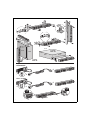
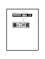
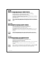
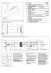
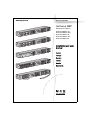
www.mgeups.com
HotSwap MBP
Maintenance ByPass
HotSwap
HotSwap
HotSwap
HotSwap
HotSwap
MBP
MBP
MBP
MBP
MBP
4 FR
4 DIN
3 BS
6 IEC
HW
Installation and user
manual
English
Français
Deutsch
Italiano
Español
Nederlands
P
T H E
U N
I N
T E
R
R
U
P
T
I
B
L
E
O
W
E
R
P
D E R
V I
R O
2
2
1
1
1
Top
2
Front
Side
UPS
Back
Back
Side
UPS
UPS < 2 kVA
+
OUT
10A
+
UPS > 2 kVA
+
OUT
16A
2 - 3400809200/AB
+
By-pass
BY PASS SWITCH
Normal
UPS ON OK to switch
By-pass
BY PASS SWITCH
Normal
UPS ON OK to switch
HotSwap MBP
3400809200/AB - 3
English
Safety guidelines to read before installing the product
◗ The product must be used indoors only.
◗ Do not place the product near liquid or in an excessively damp environment.
◗ Do not place the product directly in the sun or near a heat source.
◗ Do not let liquid or foreign objects enter the product.
◗ Ground the product using a 2P + ground socket.
◗ When installing the product, ensure that the sum of the leakage currents of the product and the devices it
supplies does not exceed 3.5 mA.
◗ The AC-power input must be connected to an appropriate electrical network protection or tap-off circuit
(fuse or circuit-breaker).
Warning: for safety reasons, only the 16A/16A lead should be used to connect the
HotSwap MBP (Maintenance Bypass) module to a UPS with a power rating greater than
2 kVA.
Use
The HotSwap MBP module makes it possible to service or even replace the UPS without affecting the
connected loads (HotSwap function).
Installation
Refer to the UPS installation and user manual.
HotSwap MBP module operation
The HotSwap MBP module has a rotary switch with two positions:
◗ Normal - the load is supplied by the UPS,
◗ Bypass - the load is supplied directly by the AC-power source.
UPS start-up with the HotSwap MBP module
1 - Check that the UPS is correctly connected to the HotSwap MBP module.
2 - Set switch to the Normal position.
3 - Start the UPS by pressing the ON/OFF button on the UPS control panel:
◗ The load is supplied by the UPS.
◗ Green LED "UPS ON - OK to switch" on the HotSwap MBP module goes ON.
HotSwap MBP module test
1 - Set switch to the Bypass position and check that the load is still supplied.
2 - Set switch back to the Normal position.
Maintenance on a UPS equipped with the HotSwap MBP module
The HotSwap MBP module makes it possible to service or even replace the UPS without affecting the
connected loads (HotSwap function).
Maintenance:
1 - Set switch to the Bypass position. The red LED on the HotSwap MBP module goes ON, indicating that
the load is supplied directly with AC power.
2 - Stop the UPS: green LED "UPS ON - OK to switch" goes OFF, the UPS can now be disconnected and
replaced.
Return to normal operation:
1 - Check that the UPS is correctly connected to the HotSwap MBP module.
2 - Start the UPS: green LED "UPS ON - OK to switch" on the HotSwap MBP module goes ON (otherwise,
there is a connection error between the HotSwap MBP module and the UPS).
3 - Set switch to the Normal position. The red LED on the HotSwap MBP module goes OFF.
4 - 3400809200/AB
Français
Consignes de sécurité, à lire avant l’installation du produit
◗
◗
◗
◗
◗
◗
Le produit doit être utilisé à l’intérieur seulement.
Ne pas placer le produit à proximité de liquide, ou dans un environnement d’humidité excessive.
Ne pas placer le produit directement au soleil ou à proximité d’une source de chaleur.
Ne pas laisser pénétrer de liquide ou d’objet étranger à l’intérieur du produit.
Relier impérativement le produit à la terre à l’aide d’une prise de courant 2 pôles + terre (2P+T).
S’assurer lors de l’installation du produit que la somme des courants de fuite du produit et des appareils
qu’il alimente ne dépasse pas 3.5 mA.
◗ La fiche d’alimentation doit être connectée à un circuit de dérivation ou de protection du réseau électrique
(fusible ou disjoncteur) approprié.
Attention : pour des raisons de sécurité, utiliser exclusivement le cordon 16A/16A pour relier le
module HotSwap MBP (Maintenance Bypass) à une ASI de puissance supérieure à 2 kVA.
Utilisation
Le Module HotSwap MBP permet la maintenance et éventuellement le remplacement de l’ASI sans
affecter l’alimentation électrique des équipements connectés (fonction HotSwap).
Installation
Se reportez au manuel d’installation et d’utilisation de l’ASI.
Fonctionnement du module HotSwap MBP
Le module HotSwap MBP utilise un commutateur rotatif à 2 positions :
◗ Normal : les équipements sont alimentés par l’ASI.
◗ By-pass : les équipements sont alimentés par le réseau électrique.
Mise en service de l’ASI avec le module HotSwap MBP :
1 - Vérifier que l’ASI est raccordée correctement au module HotSwap MBP.
2 - Placer le commutateur en position Normal.
3 - Mettre en marche l’ASI :
◗ Les équipements sont alors alimentés par l’ASI.
◗ Le voyant vert "UPS ON - OK to switch" s’allume sur le module HotSwap MBP.
Test du module HotSwap MBP
1 - Placer le commutateur en position By-pass et vérifier que les équipements sont toujours alimentés.
2 - Remettre le commutateur en position Normal.
Maintenance d’une ASI équipée d’un module HotSwap MBP
Remplacement de l’ASI sans interrompre l’alimentation électrique des équipements
connectés :
1 - Placer le commutateur en position By-pass : le voyant rouge du module HotSwap MBP s’allume pour
indiquer que les équipements sont alimentés directement par le réseau électrique.
2 - Arrêter l’ASI : le voyant vert "UPS ON - OK to switch" s’éteint, l’ASI peut alors être déconnectée et
remplacée.
Retour en fonctionnement normal :
1 - Vérifier que l’ASI est raccordée correctement au module HotSwap MBP.
2 - Mettre en marche l’ASI : le voyant vert "UPS ON - OK to switch" s’allume sur le module HotSwap MBP
(sinon il y a erreur de raccordement du module HotSwap MBP avec l’ASI).
3 - Mettre le commutateur en position Normal : le voyant rouge du module HotSwap MBP s’éteint.
3400809200/AB - 5
Deutsch
Sicherheitshinweise bitte aufmerksam vor Installierung des Gerätes lesen
◗ Das Gerät ist ausschließlich für den Gebrauch in Innenräumen bestimmt.
◗ Das Gerät darf nicht in der Nähe von Flüssigkeiten, bzw. in einer Umgebung mit übermäßiger
Luftfeuchtigkeit angebracht werden.
◗ Das Gerät darf nicht der direkten Sonnenbestrahlung ausgesetzt werden, noch in der Nähe einer
Wärmequelle angebracht werden.
◗ Das Eindringen von Flüssigkeit oder Fremdkörpern ins Geräteinnere muss verhindert werden.
◗ Das Gerät muss unbedingt an die Masse mit Hilfe einer 2 Pole + Masse Steckdose (2P+M)
angeschlossen werden.
◗ Stellen Sie bei der Installation des Gerätes sicher, dass die Summe der Streuströme des Gerätes und der
von ihm versorgten Geräte 3.5 mA nicht überschreitet.
◗ Der Netzstecker muss an eine geeignete Verzweigungs- bzw. Schutzleitung des Stromnetzes (Sicherung
oder Schalter) angeschlossen sein.
Achtung: Für den Anschluss des HotSwap MBP (Maintenance Bypass) Moduls an eine
USV mit einer Leistung von über 2 kVA darf aus Sicherheitsgründen nur das 16A/16A
Kabel verwendet werden.
Betriebszustände
Das HotSwap MBP-Modul ermöglicht die Wartung und ggf. den Austausch der USV, ohne die
Spannungsversorgung der angeschlossenen Verbraucher unterbrechen zu müssen (HotSwap-Funktion).
Aufstellung und Installation
Siehe der USV Installations- und Bedienungsanleitung.
Funktionsweise des HotSwap MBP-Moduls
An der Rückseite des HotSwap MBP-Moduls befindet sich ein Drehschalter mit 2 Schaltstellungen:
◗ Stellung Normal: Die Verbraucherversorgung erfolgt über die USV.
◗ Stellung Bypass: Die Verbraucherversorgung erfolgt aus dem Einspeisenetz.
Einschalten der USV bei Verwendung des HotSwap MBP-Moduls:
1 - Korrekten Anschluss der USV an das HotSwap MBP-Modul überprüfen.
2 - Drehschalter in die Stellung "Normal" bringen.
3 - USV durch Betätigung der EIN/AUS-Taste an der Frontseite des Geräts einschalten.
◗ Die Verbraucher werden über die USV versorgt.
◗ Die grün LED "UPS ON - OK to switch" am HotSwap MBP-Modul leuchtet auf.
Funktionstest des HotSwap MBP-Moduls.
1 - Schalter in die Stellung "By-pass" bringen und überprüfen, dass die Verbraucher weiter versorgt werden.
2 - Drehschalter erneut in die Stellung "Normal" zurückstellen.
Wartung und Service bei USV-Anlagen mit HotSwap MBP-Modul
Wartung:
1 - Drehschalter in die Stellung "By-pass" bringen. Die rote LED des HotSwap MBP-Moduls leuchtet auf
und zeigt an, dass die angeschlossenen Verbraucher direkt aus dem Netz versorgt werden.
2 - USV durch Betätigung der EIN/AUS-Taste an der Frontseite des Geräts ausschalten. Die grün LED
"UPS ON - OK to switch" erlischt; anschließend kann die USV abgeklemmt und ausgetauscht werden.
Rückkehr in Normalbetrieb:
1 - Korrekten Anschluss der USV an das HotSwap MBP-Modul überprüfen.
2 - USV durch Betätigung der EIN/AUS-Taste an der Frontseite des Geräts einschalten. Die grün LED
"UPS ON - OK to switch" am HotSwap MBP-Modul leuchtet auf (andernfalls liegt ein Anschlussfehler
zwischen USV und HotSwap MBP-Modul vor).
3 - Drehschalter in die Stellung "Normal" bringen; die rote LED am HotSwap MBP-Modul erlischt.
6 - 3400809200/AB
Italiano
Leggere attentamente le istruzioni di sicurezza prima dell’installazione del
prodotto
◗
◗
◗
◗
◗
◗
Il prodotto deve essere utilizzato esclusivamente all’interno.
Non installare il prodotto nei pressi di liquidi o in un ambiente con umidità eccessiva.
Non installare il prodotto direttamente al sole o nei pressi di una fonte di calore.
Non lasciare penetrare liquidi o oggetti estranei all’interno del prodotto.
Collegare tassativamente il prodotto alla terra con una presa di corrente 2 poli + messa a terra (2P+T).
Al momento dell’installazione del prodotto accertarsi che la somma delle correnti di fuga del prodotto e
degli apparecchi che alimenta non superi 3.5 mA.
◗ La presa di alimentazione deve essere collegata ad un circuito di derivazione o di protezione della rete
elettrica (fusibile o interruttore) adeguato.
Attenzione: per motivi di sicurezza, utilizzare esclusivamente il cavo 16A/16A per
collegare il modulo HotSwap MBP (Manutenzione Bypass) ad un UPS di potenza
superiore a 2 kVA.
Utilizzo
La funzione del modulo HotSwap MBP è quella di consentire la manutenzione ed eventualmente la
sostituzione dell’UPS senza interferire sull'alimentazione elettrica delle apparecchiature collegate (funzione
HotSwap).
Installazione
Vedere il manuale di installazione e di utilizzazione dell’UPS.
Funzionamento del modulo HotSwap MBP
Il modulo HotSwap MBP utilizza un commutatore rotativo a 2 posizioni:
◗ Normale: gli impianti sono alimentati dall’UPS.
◗ By-pass: gli impianti sono alimentati dalla rete elettrica.
Attivazione dell’ASI con il modulo HotSwap MBP:
1 - Verificare che l’UPS sia collegato correttamente al modulo HotSwap MBP.
2 - Portare il commutatore in posizione Normale.
3 - Avviare l’UPS premendo il pulsante Avvio/Arresto sulla parte anteriore dell'UPS.
◗ Gli impianti sono ora alimentati dall’UPS.
◗ La spia verde "UPS ON - OK to switch" si accende sul modulo HotSwap MBP.
Test del modulo HotSwap MBP
1 - Portare il commutatore in posizione By-pass e verificare che gli impianti continuino ad essere alimentati.
2 - Riportare il commutatore in posizione Normale.
Manutenzione di un ASI dotato di modulo HotSwap MBP
Manutenzione:
1 - Portare il commutatore in posizione By-pass: la spia rossa del modulo HotSwap MBP si accende per
segnalare che gli impianti sono alimentati direttamente dalla rete elettrica.
2 - Arrestare l’UPS premendo il pulsante Avvio/Arresto sulla parte anteriore dell'UPS: la spia verde "UPS
ON - OK to switch" si spegne e a questo punto l’UPS può essere scollegato e sostituito.
Ritorno al funzionamento normale:
1 - Verificare che l’UPS sia collegato correttamente al modulo HotSwap MBP.
2 - Avviare l’UPS premendo il pulsante Avvio/Arresto sulla parte anteriore dell'UPS: la spia verde "UPS ON
- OK to switch" si accende sul modulo HotSwap MBP (in caso contrario si è verificato un errore di raccordo
del modulo HotSwap MBP all’UPS).
3 - Portare il commutatore in posizione Normale: la spia rossa del modulo HotSwap MBP si spegne.
3400809200/AB - 7
Español
Consignas de seguridad leer antes de instalar el producto
◗ El producto debe utilizarse únicamente al interior.
◗ No colocar el producto cerca de líquidos o en un entorno de humedad excesiva.
◗ No colocar el producto directamente bajo los rayos del sol ni cerca de una fuente de calor.
◗ No dejar que penetre líquido u objeto ajeno al interior del producto.
◗ Conectar imperativamente el producto a tierra utilizando una toma de corriente de 2 polos + tierra (2P+T).
◗ Cerciorarse durante la instalación del producto que la suma de las corrientes de fuga del producto y de
los aparatos que alimenta no excede 3.5 mA.
◗ La toma de la red debe estar conectada a un circuito de derivación o de protección de la red eléctrica
(fusible o interruptor automático) apropiado.
Atención: por razones de seguridad, utilizar exclusivamente el cable 16A/16A para
conectar el módulo HotSwap MBP (Maintenance Bypass) a una SAI de potencia
superior a 2 kVA.
Utilización
La función del módulo HotSwap MBP es permitir el mantenimiento y, eventualmente, la sustitución del SAI
sin que ello afecte a la alimentación eléctrica de los equipos conectados (función HotSwap).
Instalación
Véase el manual de instalación y empleo del SAI.
Funcionamiento del módulo HotSwap MBP
El módulo HotSwap MBP utiliza un conmutador rotativo de 2 posiciones:
◗ Normal: los equipos están siendo alimentados por el SAI.
◗ Bypass: los equipos están siendo alimentados por la red eléctrica.
Puesta en servicio del SAI con el módulo HotSwap MBP:
1 – Comprobar que el SAI esté correctamente conectado al módulo HotSwap MBP.
2 – Colocar el conmutador en posición Normal.
3 – Poner en marcha el SAI pulsando el botón Marcha/Parada en la cara delantera del SAI.
◗ Los equipos están siendo alimentados ya por el SAI.
◗ El indicador luminoso verde "UPS ON - OK to switch" se enciende en el módulo HotSwap MBP.
Test del módulo HotSwap MBP
1 – Colocar el conmutador en posición Bypass y comprobar que los equipos sigan estando alimentados.
2 – Volver a poner el conmutador en posición Normal.
Mantenimiento de un SAI equipado con un módulo HotSwap MBP
Mantenimiento:
1 – Colocar el conmutador en posición Bypass: el indicador luminoso rojo del módulo HotSwap MBP se
enciende para indicar que los equipos están siendo alimentados directamente por la red eléctrica.
2 – Parar el SAI pulsando el botón Marcha/Parada en la cara delantera del SAI:
El indicador luminoso verde "UPS ON - OK to switch" se apaga, ya se puede desconectar el SAI y
sustituirlo.
Vuelta a funcionamiento normal:
1 – Comprobar que el SAI esté correctamente conectado al módulo HotSwap MBP.
2 – Poner en marcha el SAI pulsando el botón Marcha/Parada en la cara delantera del SAI: el indicador
luminoso verde "UPS ON - OK to switch" se enciende en el módulo HotSwap MBP (en caso contrario, hay
un error en la conexión entre el módulo HotSwap MBP y el SAI).
3 – Poner el conmutador en posición Normal: el indicador luminoso rojo del módulo HotSwap MBP se
apaga.
8 - 3400809200/AB
Nederlands
Veiligheidsaanbevelingen lees deze aanbevelingen helemaal door alvorens het
product te installeren
◗ Het product mag uitsluitend binnenshuis gebruikt worden.
◗ Plaats het product nooit in de buurt van vloeistoffen, of in een te vochtige omgeving.
◗ Vermijd blootstelling van het product aan direct zonlicht en plaats het nooit in de buurt van een
warmtebron.
◗ Zorg ervoor dat er geen vloeistoffen of vreemde voorwerpen in het product kunnen binnendringen.
◗ Het product moet verplicht geaard worden via een 2-polige stekker + aarde (2P+A).
◗ Bij installatie van het product moet gecontroleerd worden of de som van de lekstromen van het product
en de apparatuur die het van energie voorziet niet groter is dan 3,5 mA.
◗ De netaansluiting moet worden aangesloten op een geschikt omleidings- of beveiligingscircuit (zekering
of schakelaar).
Waarschuwing: gebruik om veiligheidsredenen uitsluitend de 16A/16A kabel om de
HotSwap MBP module (Maintenance Bypass) aan te sluiten op UPS’en met een
vermogen groter dan 2kVA.
Gebruik
Met een HotSwap MBP-module kan de UPS worden onderhouden en eventueel vervangen zonder
gevolgen voor de elektrische voeding van de aangesloten apparatuur (HotSwap-functie).
Installatie
Zie de installatie- en gebruikershandleiding van de UPS.
Werking van de HotSwap MBP-module
De HotSwap MBP-module is voorzien van een draaischakelaar met 2 standen:
◗ Normal: de apparatuur wordt gevoed door de UPS.
◗ By-pass: de apparatuur wordt gevoed door het elektriciteitsnet.
In bedrijf stellen van de UPS met de HotSwap MBP-module:
1 - Controleer of de UPS goed op de HotSwap MBP-module is aangesloten.
2 - Zet de schakelaar op Normal.
3 - Start de UPS door op de Aan/Uit-knop aan de voorkant van de UPS te drukken.
◗ De apparatuur wordt nu door de UPS gevoed.
◗ Groen lampje "UPS ON - OK to switch" gaat nu branden op de HotSwap MBP-module.
Testen van de HotSwap MBP-module
1 - Zet de schakelaar op By-pass en controleer of de apparatuur nog steeds wordt gevoed.
2 - Zet de schakelaar weer op Normal.
Onderhoud van een UPS met een HotSwap MBP-module
Onderhoud:
1 - Zet schakelaar op By-pass: het rode lampje van de HotSwap MBP-module gaat branden om aan te
geven dat de apparatuur rechtstreeks vanuit het elektriciteitsnet wordt gevoed.
2 - Schakel de UPS uit door op de Aan/Uit-knop aan de voorkant van de UPS te drukken: het groen lampje
"UPS ON - OK to switch" gaat uit, de UPS kan nu worden afgekoppeld en vervangen.
Terug naar normaal bedrijf:
1 - Controleer of de UPS goed is aangesloten op de HotSwap MBP-module.
2 - Schakel de UPS in door op de Aan/Uit-knop op de voorkant van de UPS te drukken: het groen lampje
"UPS ON - OK to switch" gaat branden op de HotSwap MBP-module (zo niet, dan is er een probleem met
de aansluiting van de HotSwap MBP-module op de UPS).
3 - Zet de schakelaar op Normal: het rode lampje van de HotSwap MBP-module gaat uit.
3400809200/AB - 9
Norsk
Sikkerhetsinstrukser som må lese før produktet installeres
◗
◗
◗
◗
◗
◗
Produktet må kun brukes innendørs.
Produktet må ikke plasseres i nærheten av væsker eller i et miljø med høy fuktighet.
Produktet må ikke utsettes for direkte sollys eller plasseres i nærheten av en varmekilde.
Det må ikke komme væske eller fremmedlegemer inn i produktet.
Produktet må jordtilkoples ved hjelp av 2-polet jordkontakt + jord (2P+J).
Ved installasjon av produktet må man forsikre seg om at summen av lekkasjestrømmen fra produktet og
de apparatene som får tilførsel fra dette ikke overstiger 3,5 mA.
◗ Nettkontakten må være koplet til en egnet derivasjons- eller beskyttelseskrets (sikring eller strømbryter)
på den elektriske kretsen.
OBS!: av sikkerhetsmessige årsaker, er det kun ledningen 16A/16A som må brukes for
å kople modulen HotSwap MBP (Maintenance Bypass) til en UPS med større effekt enn
2 kVA.
Svenska
Säkerhetsföreskrifter: läses innan produkten installeras
◗
◗
◗
◗
◗
◗
Produkten får enbart användas inomhus.
Placera aldrig produkten i närheten av vätska eller i mycket fuktig omgivning.
Placera inte produkten direkt i solen eller i närheten av en värmekälla.
Låt inte vätska eller främmande föremål tränga in i produkten.
Anslut obligatoriskt produkten till jorden via ett uttag med 2 poler + jord (2P+J).
Se vid installationen till att den totala läckströmmen från produkten och de apparater den försörjer inte
övergår 3.5 mA.
◗ Nätuttaget ska vara anslutet till en förbikopplingskrets eller annat lämpligt elnätsskydd (säkring eller
frånkopplare).
Varning: Av säkerhetsskäl får endast sladden 16A/16A användas för att ansluta
modulen HotSwap MBP (Maintenance Bypass) till en ASI med en effekt över 2 kVA.
Suomi
Turvallisuusohjeet: luettava ennen tuotteen asentamista
◗
◗
◗
◗
◗
◗
Tuotetta saa käyttää ainoastaan sisätiloissa.
Älä sijoita tuotetta nesteiden lähelle tai liian kosteaan ympäristöön.
Älä sijoita tuotetta suoraan auringonpaisteeseen tai lämmönlähteiden lähelle.
Älä päästä tuotteeseen nesteitä tai vieraita esineitä.
Maadoita tuote käyttämällä 2P+-maadoituspistoketta.
Kun asennat tuotteen, varmista, että tuotteen ja siihen kytkettyjen laitteiden vuotovirtojen yhteenlaskettu
määrä ei ylitä 3,5 mA:a.
◗ Verkkopistoke on kytkettävä asianmukaiseen sähköverkon suoja- tai katkaisupiiriin (sulake tai
suojakytkin).
Huomio: turvallisuussyistä käytä ainoastaan 16A/16A-kaapelia, jos liität HotSwap MBP
(Maintenance Bypass) -moduulin UPS-laitteeseen, jonka teho ylittää 2 kVA.
10 - 3400809200/AB
Dansk
Sikkerhedsanvisninger: Læs anvisningerne, før produktet installeres
◗
◗
◗
◗
◗
◗
Produktet må kun anvendes indendørs.
Installer ikke produktet i nærheden af væske eller i et miljø med høj fugtighed.
Installer ikke produktet i direkte sollys eller i nærheden af en varmekilde.
Der må ikke trænge væske eller fremmedlegemer ind i produktet.
Produktet skal tilsluttes jord ved hjælp af et topolet el-stik med jord (2 p + j).
Kontroller i forbindelse med installation af produktet, at summen af lækstrøm fra produktet og de
apparater, det strømforsyner, ikke overstiger 3,5 mA.
◗ Netstikket skal være tilsluttet et passende kredsløb med jord eller beskyttelse af ledningsnettet (sikring
eller hfi-relæ).
Obs: Anvend af sikkerhedsmæssige grunde kun 16A/16A-ledningen til at forbinde
HotSwap MBP-modulet (Maintenance Bypass) til en ASI med en effekt på mere end
2 kVA.
Português
Instruções de segurança: ler antes da instalação do produto
◗
◗
◗
◗
◗
◗
O produto deve ser unicamente utilizado no interior.
Não coloque o produto na proximidade de líquidos, ou num ambiente de humidade excessiva.
Não coloque o produto directamente ao sol ou na proximidade de uma fonte de calor.
Não deixe penetrar líquido ou objecto estranho dentro do produto.
Ligue imperativamente o produto à terra graças a uma ficha de corrente 2 pólos + terra (2P+T).
Verifique durante a instalação do produto que a soma das correntes de fuga do produto e dos aparelhos
que o mesmo alimenta não ultrapassa 3.5 mA.
◗ A tomada sector deve estar ligada a um circuito de derivação ou de protecção da rede eléctrica (fusível
ou disjuntor) apropriado.
Atenção: por razões de segurança, utilize exclusivamente o cabo 16A/16A para ligar o
módulo HotSwap MBP (Maintenance Bypass) a um AEI com uma potência superior a
2 kVA.
Polski
Zalecenia bezpieczeństwa: przeczytać przed instalacją produktu
◗ Produkt mona używać wyłącznie w pomieszczeniach.
◗ Nie umieszczać produktu w pobliużu płynów lub w miejscach o wysokiej wilgotności.
◗ Nie umieszczać produktu bezpośrednio na słońcu lub w pobliżu żródła ciepła.
◗ Nie dopuszczać do przedostania się płynów lub ciał obcych do wnętrza produktu.
◗ Obowiązkowo podłączać produkt do uziemienia przy pomocy gniazdka z dwoma bolcami i uziemieniem.
◗ Upewnić się, że w czasie instalacji produktu suma prądów upływowych produktu i zasilanych urządzeń
nie przekracza 3.5 mA.
◗ Gniazdko zasilania musi być podłączone do obwodu odprowadzającego lub zabezpieczającego sieć
elektryczną (bezpiecznik lub wyłącznik).
Uwaga: ze względów bezpieczeństwa, używać wyłącznie przewodu 16A/16A do
podłączenia modułu HotSwap MBP (konserwacja obejścia) o ASI mocy przekraczającym 2 kVA.
3400809200/AB - 11
Technical characteristics
HotSwap MBP models : 4 FR, 4 DIN, 3 BS, 6 IEC, HW
Input
IEC 320 C20 16A
except terminal blocks on HotSwap MBP HW
Output
HotSwap MBP 4 FR :
HotSwap MBP 4 DIN :
HotSwap MBP 3 BS :
HotSwap MBP 6 IEC :
HotSwap MBP HW :
Dimensions
(HxLxD)
5.2 cm x 19 inches x 12 cm
Performances
Nominal voltage
Frequency
Input nominal current
Maximal power
Standards
Product
Marking
200/208/220/230/240 V
50/60 Hz
16 A
3680 VA
HotSwap MBP 4 FR :
HotSwap MBP 4 DIN :
HotSwap MBP 3 BS :
HotSwap MBP 6 IEC :
HotSwap MBP HW :
Storage -25°C to 55°C, operation 0°C to 45°C
Storage 10% to 90%, operation 20% to 90%
Transportation up to 12000 m, operation up to 1500 m
T H E U N I N T E R R U P T I B L E P O W E R P R O V I D E R
140, Avenue Jean Kuntzmann
ZIRST - Montbonnot St Martin
38334 - Saint Ismier Cedex - France
www.mgeups.com
3400809200/AB
IEC60884-1
DIN 49440-1, DIN 49440-5, DIN49440-6
BS 1363
IEC 60320-1, EN 60320-1
EN 50091, IEC 60950
CE
Environment
Temperature
Humidity
Altitude
MGE UPS SYSTEMS
4 USE A socket-outlets + 1 IEC 320 C19 16A
4 DIN A socket-outlets + 1 IEC 320 C19 16A
3 BS 13A socket-outlets + 1 IEC 320 C19 16A
6 IEC 320 C13 10A + 1 IEC 320 C19 16A
Terminal blocks