1
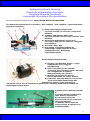
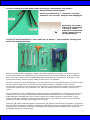
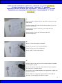
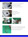
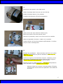
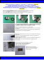
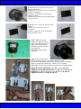
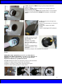
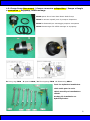
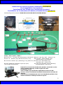
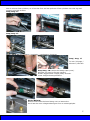
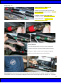
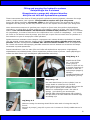
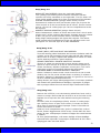
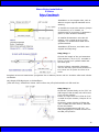
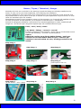
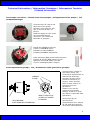
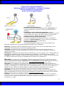
Installation Instruction
(Owners Manual)
Installationsmanual
Hydraulic Steering Systems
Directions Idrauliques
Timonerie Idrauliche – Idroguide
Hydrauliskt Styrsystem
Outboard – Inboard – Stern-Drive
Hors-Bord Inboard Stern-Drive
Fuoribordo – Entrobordo – Entrofuoribordo
Utomboardare – Inombordare – Drev
English – Francais – Italiano - Svenska
Techno Italia KFT
Hungary – EU
[email protected]
www.hydrodrive.eu
Outboard Hydraulic Steering
Directions Hydrauliques Hors-Bord
Timoneria Idraulica Fuoribordo
Hydrauliskt Styrsystem för utombordare
Models/désignation/modelli/modell: MF90-MF120-MF150-MF300-MF350
The hydraulic steering kit box contents / Kits complets / Kits completi / Den hydrauliska
styrpaket innehåller:
1) Pump with fittings/Pompe avec
raccords/Pompa con raccordi/ Pump med
tillbehör.
2) Cylinder with fittings/Vérin avec
raccords/Cilindro con raccordi/ Cylinder med
tillbehör.
3) Hosing set with fittings/Tuyau avec
raccords/Tubazione con raccordi/ Slangset
med tillbehör.
4) Oil/Huile/Olio/ Olja.
5) Easy filling oil system/Sistème de
remplissage rapide/Sistema di facile
riempimento olio/ Behändigt
oljefyllnadssystem.
Pump/Pompe/Pompa/Pump:
A) Oil filler cap/Bouchon d’huile / Tappo
riempimento olio/ Plugg för
oljepåfyllning.
B) Hose connection to the cylinder
/Raccords pour liaison au verin/ Raccordi
per collegamento al cilindro/
Slanganslutning till cylindern.
C) Steering wheel key/Clè pour le
Volant/Chiavetta per ruota/ Rattkil.
D) (Optional) Seal cap, Remove only in case
seals need replacement/Siege des
guarnitures/Inserto porta guarnizione,
rimuovere solo in caso di sostituzione guarnizioni/ Packbox, Demonteras endast om
packningen behöver bytas.
Cylinder/Vérin/Cilindro/Cylinde
r:
A: Engine tilt tube shaft/barra
tubo motore/ Styrrösarm.
B: Steering Connection
Arm/barra di rinvio/ Länkarm
för styranslutning
V: Bleeder Valve/clapet de
purge/valvole di spurgo aria/
Luftningsnippel.
2
P: Hose connection to the Helm Pump/raccordi per collegamento alla pompa/
Slanganslutning till styrpump.
Hosing set with fittings / Tuyau avec raccords /
Tubazione con raccordi/ Slangset med kopplingar.
Easy filling oil system /
Sistème de remplissage
–de purge- rapide /
Sistema di riempimento
rapido/ Enkelt system
för oljepåfyllning .
Tooling for pump installation/ clefs-outils pour le pompe / chiavi utensili/ Verktyg som
behövs för pumpinstallation:
Before proceeding with installation, please read these instructions carefully. Hydrodrive cannot
accept responsibility for installation where instructions have not been followed, where substitute
parts have been used or where modifications have been made to our products. Hydrodrive helm
pumps have a max. pressure valve inside so total lock is not possible.
Avant de commercer avec l'installation, nous vous prions de lire très attentivement et avancer selon
les instructions. Hydrodrive ne va pas donner garantie quand l'installation n'été pas faite
correctement, quand les pièces original sont été forcés, quand les pièces original sont été modifiés.
Les pompes Hydrodrive ont à l'antérieur une valve de haute pression et s'arrête a peut prés au
100%.
Prima di procedure con l’ installazione, preghiamo leggere attentamente e seguire queste istruzioni,
la Hydrodrive non si ritiene responsabile di acconsentire alla garanzia dove l’ installazione non è
stata eseguita correttamente, dove le parti originali sono state sostituite o manomesse o dove
fossero state fatte modifiche. Le pompe Hydrodrive hanno internamente una valvola di massima
pressione, quindi è normale il bloccaggio non al 100%.
Innan du går vidare med att installera styrpumpen, läs igenom instruktionerna noggrant. Hydrodrive
kan inte hållas ansvarigt för felaktig installation, installation med icke-originaldelar och i fall där våra
produkter har modifierats. Hydrodrive styrpumpar har inbyggd säkerhetsventil vilket medför att
fullständig stängning inte är möjlig.
3
Helm pump installation (outboard / inboard) “F” front (standard)
Pompe installation (hors-bord / inboard) “F” applique
Installazione della Pompa (per fuoribordo / entrobordo) “F” frontale
Installation av styrpump (utombordare / inombordare) “F” front
(standard)
1:
Place the helm template (Front Mt) where required on the
dash panel.
On doive mettre le dessin de percement (dima) (F) sur le
panneau du bateau.
Posizionare la dima di foratura (F) sul pannello dell’
imbarcazione.
Placera mallen (Front Mt) på önskad plats på
instrumentpanelen.
2:
Drill 4 x 7mm holes where indicated.
Percer les 4 trous de 7 mm de diamètre.
Forare i 4 fori da 7 mm di diametro.
Borra 4 hål (7 mm) enligt mallen.
3:
Drill 4x holes in the corners of the valve location to enable
cut out with a jig saw.
Percer les autre 4 trous du même diamètre pour préparer
le coupe pour la clapet (valve).
Forare altri 4 fori stesso diametro per preparare il taglio per
lo spazio valvola.
Borra 4 hål, ett i varje hörn enligt mallen så det går att
använda en sticksåg för att såga ut resten.
4
4:
Cut out the lock valve area. 50x90mm (Ǿ 90mm )
Couper l’espace valve (clapet) Ǿ 90mm
Tagliare lo spazio valvola Ǿ 90mm
Saga ut det markerade omradet (Ǿ 90mm )
5:
Remove the template.
Enlever le dessin de percement.
Rimuovere la dima di foratura.
Ta bort mallen.
6:
Take off the screws and the fittings caps from the pump.
Enlever les écrous et les bouchons raccords de la pompe.
Rimuovere i dadi e i tappi raccordi dalla pompa.
Ta av skruvar och hylsor från pumpen.
5
7:
Install the helm pump in the dash panel.
Mettre la pompe dans les trous que sont été fait.
Infilare la pompa dentro i fori praticati.
Installera styrpumpen på instrumentpanelen.
8:
(Rear) Screw the nuts with the washers (4x).
Ensure the helm is firm and cannot move.
(Derrière le panneau) visser les 4 écrous avec les rondelle.
(Dietro al pannello) Avvitare i 4 dadi con le rondelle.
Använd brickor och dra fast muttrarna på baksidan. Se till att
pumpen sitter ordentligt fast.
9:
Fittings cap installation – Place the Olive and lock nut in place.
Warning: right position as picture indication! Close only by
hand, not strong!
Insérer les ogives et les bouchons-raccord - Attention, suivre
exactement l'emplacement comme démontré dans la figure.
Fermer seulement manuellement! (avec la main)
Inserire le ogive e i tappi raccordo – Attenzione alla posizione
come indicato in figura! Chiudere solo a mano!
Montera hylsan och muttern. Obs kontrollera så hylsan
monterars på samma sätt som på bilden. Dra endast åt
för hand!
6
10:
Hoses installation: FOLLOW the COLOURS!
Ensure hoses are inserted green to green
and red to red. As indicated.
Installer les tuyau dans les raccords comme
démontré dans la figure: SUIVRE LES
COULEURS!
Installare I tubi nei raccordi come indicato in
figura: SEGUIRE I COLORI!
Slanginstallation:
FÖLJ FÄRGERNA! Montera grön slang till
grön koppling och röd slang till röd koppling,
enligt bilden.
11:
Close the fittings cap as indicated, tighten firmly! After tightening ensure that the hose will not pull
out.
Visser les bouchons-raccord comme les indications, serré!
Stringere i dadi raccordo come indicato, stretti!
Montera anslutningarna enligt bilden och dra åt ordentligt. Kontrollera att slangen inte går att dra
ut.
Tilt Helm option: TH6-TH15-TH30
Angle 6°
Angle 15°
Angle 30°
7
Pump installation (outboard / inboard) “L” back mount (option)
Pompe installation (horse-bord / inboard) “L” encastre
Installazione della Pompa (per fuoribordo / entrobordo) “L” flangia
Pumpinstallation (utombordare / inombordare) “L” frontmontage (möjligt
alternativ)
With the option kit PL140 the front “F” pump can became “L” back mount pump.
Avec le kit PL140 la pompe frontal "F" peut devenir a encastrer "L".
Con il kit PL140 la pompa frontale “F” diventa pompa ad incastro (a flangia) “L”.
Med kittet PL140 kan front “F” pumpen bli “L” infälld.
1.1: Flange pump, front mount / pompe encastrer montage a
l’ applique / pompa flangia montaggio frontale.
1.1: Put the drilling template (F) on boat panel.
On doive mettre le dessin de percement (dima) (F) sur le panneau
du bateau.
Posizionare la dima di foratura (F) sul pannello dell’ imbarcazione.
Fäst borrmallen (F) på instrumentpanel.
1.2: Drill 4x holes same dia. 7mm (0,3”) to prepare the cutting for
valve place.
Percer les 4 trous du même diamètre (7mm) pour préparer le
coupe pour la clapet (valve).
Forare i 4 fori stesso diametro (7mm) per preparare il taglio per lo
spazio valvola.
Borra 4 hål (7 mm) som förberedelse för att såga upp för
backventilen.
1.3: Cut the valve space 50x90mm (2”x3,55”).
Couper l'espace valve (clapet) 50x90mm.
Tagliare lo spazio valvola 50x90mm.
Såga enligt mall (50x90 mm).
1.4: Remove the template.
Enlever le dessin de percement
Rimuovere la dima di foratura.
Ta bort mallen.
8
1.5: Mark the 4x holes on the pump
flange with a pen.
Marquer avec le crayon les 4 trous de la
pompe a encastre.
Marcare con la penna i 4 fori della
flangia pompa.
Markera de 4 hålen genom plastringen
med en penna.
1.6: Drill 4 x 7 mm dia. holes for the
flange.
Percer les 4 trous de 7 mm de
diamètre.
Forare i 4 fori da 7 mm di diametro.
Borra 4 hål (7 mm).
1.7: Install the pump
inside the (panel) holes.
Mettre la pompe dans les
trous que sont été fait.
Infilare la pompa dentro i
fori praticati.
Installera pumpen från
baksidan.
1.8: (Rear) Fix the helm
pump in place with the 4 washers and lock nuts.
(Derrière le panneau) visser les 4 écrous avec les rondelle.
(Dietro al pannello) Avvitare i 4 dadi con le rondelle.
(Baksidan) Fixera styrpumpen med 4 brickor och låsmuttrar.
Make the same operation page 6/7 point 9-10-11
Répéter les meme opérations pag. 6/7 points 9-10-11
Ripetere le stesse operazioni pag. 6/7 punti 9-10-11
Upprepa sida 6/7 punkt 9-10-11
9
1.2 Flange Pump Back mount / Pompe a l’ encastre r / Pompa a flangia /tyrpump
infällt montage
1.2.1: Place the drilling template (F) on dash panel.
On doive mettre le dessin de percement (dima) (F) sur le
panneau du bateau.
Posizionare la dima di foratura (F) sul pannello dell’
imbarcazione.
Placera borrmallen (F) på instrumentpanelen.
1.2.3: Drill the 7 mm dia. (0,3”) (4x holes).
Percer les 4 trous de 7 mm de diamètre.
Forare i 4 fori da 7 mm di diametro.
Borra 4 hål (7 mm).
1.2.4: Drill some holes same dia. to prepare the round
cutting (DIA. 114-115mm 4,5”) for pump place.
Percer quelques autres trous du même diamètre pour
préparer le coupe pour la pompe (diam. 114-115mm).
Forare altri fori stesso diametro per preparare il taglio per
lo spazio pompa (diam. 114-115mm).
Borra några hål (7 mm) som förberedelse för att såga runt
för pumpen (ø 114-115 mm).
1.2.5: Cut the round pump space (DIA. 114-115mm 4,5”).
Couper l'espace pour la pompe (diam. 114-115mm).
Tagliare lo spazio tondo per la pompa.
Såga runt enligt bild (ø 114-115 mm). Använd sticksåg.
10
1.2.6: Install the FR10 fixing ring for pump inside the
(panel) holes.
Mettre le FR10 anneau de fixation de le pompe dans les
trous que sont été fait.
Infilare il fixing ring FR10 della pompa dentro i fori praticati.
Installera fixeringsringen (FR10) för pumpen i de borrade
hålen.
1.2.7: Remove the oil cap from
the pump.
Enlever les bouchons de l’ huile de
la pompe.
Rimuovere il tappo olio dalla
pompa.
Ta bort oljepluggen från pumpen.
1.2.8: Install the pump
on the back side of the
panel (hole).
Encastrer la pompe
derrière le panneau
dans les trous que sont
été fait.
Infilare la pompa dietro
il pannello dentro il foro
praticato.
Installera pumpen från baksidan av panelen.
1.2.9:
Make the same operation page 6/7 point 8-9-10-11
Répéter les même opérations page 6/7 points 8-9-10-11
Ripetere le stesse operazioni pag. 6/7 punti 8-9-10-11
Repetera sidorna 6/7 punkt 8-9-10-11
1.2.10: Install the wheel on the helm pump as pictures show.
Installer le volant comme signé dans les figures.
Installare il volante (ruota) come indicato nelle figure.
Installera ratten på styrpumpen enligt bilden.
11
1.3: Flange Pump Rear mount / Pompe a encastre a disparition / Pompa a flangia
a scomparsa / Styrpump, infällt montage
AD10 spacer kit to have Rear Mount Helm Pump.
AD10 kit anneau espacé pour le pompe a disparition.
AD10 kit distanziali per montaggio pompa a scomparsa
AD10 Distansringar för infällt montage av styrpump.
B: fixing ring FR10
A: spacer AD10 / B: Fixeringsring FR10
A: Distansring AD10
Tools for Cylinders installation.
clefs-outils pour le verin.
chiavi utensili per installazione
cilindri.
Verktyg för installation av
hydraulcylindrar.
12
Outboard front mount Cylinder installation (standard)
Verin installation (horse-bord)
Installazione del Cilindro per fuoribordo (frontale)
Installation av frontmonterad Cylinder (Utombordare) (standard)
Models/désignation/modelli: MC80-MC100-MC120-MC150-MC200-MC300
Parts / Part / Parti / Delar :
A: 050.01.07 – Tilt tube rod /Styrrörsarm (050.01.07) B: M12 - Nut (2x)/ M12 - Mutter (2 st)
C: Dia. 12 – Washer (2x)/ Brickor Ø 12mm (2 st)
D: 12x24x2 – Nylon washer (3x)/
Nylon bricka (3 st) 12x24x2
E: 025.02.11 Busher (2x)/ Bussning (2 st) (025.02.11) F: 025.02.12 Adjustable ring/
Justerbar ring (025.02.12)
G: 3/8”-24UNF-2A Complete engine pin joint/
V: 724.00.14 Breather valves (bleeder)/
3/8”-24UNF-2A Motorbult
Luftningsnipplar (724.00.14)
Hydrodrive front mount Outboard Cylinders series MC can be
easily installed directly on the engine tilt tube!
Installation facile!
Tutti I Cilindri per fuoribordo Hydrodrive della serie MC
possono essere facilmente installati direttamente sul tubo del
motore!
Hydrodrives frontmonterade serie av Utombordscylindrar kan
enkelt installeras direkt på motorns styrrör.
13
Step/ Steg: 1
Step/ Steg: 2
Step/ Steg: 3
Step/ Steg: 4
Note/Notera: Put more nylon washer (D) in case to compensate more space.
Insérer plus de (rondelle) en nylon pour avoir plus d'espace.
Inserire più rondelle in nylon (D) per compensare maggior spazio.
Sätt på så många nylonbrickor som behövs.
Step/ Steg: 5
Step/ Steg: 6
14
Step/Steg: 7
Push the rod (A) into
the engine tilt tube
Pousser la verge
(angel) dans le tuyau
moteur.
Spingere l’ asta (A)
dentro il tubo motore.
Tryck styrrörsarmenA)
in i styrröret på
motorn.
Step/Steg: 8
Step/Steg: 9
Step/Steg: 10
Step/Steg: 11
15
Step/Steg: 12
Make regulation with adjustable ring (F) that
the cylinder horizontal back-lash will be max.
0,5mm (0,02”), than lock the screw on the
adjustable ring. In case of more space
between the engine tilt tube and the cylinder
brackets, set up other nylon washers (D).
Régler le bague (F) pour obtenir avec le vérin
un jeu horizontal de 0,5 mm au maximum.
Dans le cas de plus grand jeu entre le tuyau
moteur et la étrier vérin, insérer autres
(rondelle) en nylon (D).
Regolare l’ anello (F) in modo che il cilindro
abbia un gioco orizzontale di max. 0,5mm. In
caso di maggiore gioco tra il tubo motore e la
staffa cilindro, inserire altre rondelle nylon
(D).
Justera den runda muttern (F) så att cylinderns horisontala spelrum är max 0,5 mm, lås skruven på
muttern. Om spelrummet är större än 0,5 mm montera ytterligare nylonbrickor.
1
Note/Notera:
In case of engine tilt tube different length, play to set
up bush (E) and – or nylon washers (D) (photo 1) or
take off the adjustable ring (F) installing just the bush
(E) with or without the nylon washer (D) (photo 2).
Dans le cas que ont a longueur différent du tuyau
moteur, insérer la boucle (E) et/où les (rondelle) en
nylon (figure 1) où enlever le bague de réglage et
insérer seulement la boucle (E) avec où non la
(rondelle) en nylon (D) (figure 2).
In caso di lunghezze differenti del tubo motore,
inserire la boccola (E) o/e le rondelle in nylon (D)
(foto 1) o togliere l’ anello di regolaz. (F) inserendo
solamente la boccola (E) con/senza la rondella in
nylon (D) (foto 2).
Om styrröret har en icke passande längd, använd
medföljande bussningar och nylonbrickor (foto 1) eller
ta bort den justerbara ringen (F) och använd bara bussningen (E) med eller utan nylonbrickor (foto
2).
2
Step/Steg: 13
Note/ Notera: When tightening cylinder, ensure that there is
a small vertical back-lash, so the cylinder can move with
engine trim operation.
En bloquent le vérin, laisser un petit jeu vertical pour laisser
bouger le vérin dans la situation de trim
Bloccando il cilindro, lasciare un piccolo gioco verticale in modo
che il cilindro possa muovere in caso di trim.
16
När du skruvar fast cylindern, se till att det finns ett litet spelrum så att cylindern kan röra sig med
motorns trim/tilt-rörelser.
Step/Steg: 14
Step/Steg: 15
Step/Steg: 16 Adjustment / regulation / regolazione/ Justering
Step/ Steg: 17
To lock / blocage /
bloccare / Lås fast
Step/Steg: 18 Loosen the fittings caps (nuts).
Dévisser un peut les écrous-raccord.
Svitare leggermente I tappi (dadi) raccordi.
Lossa slanganslutningsmuttern.
Note/Notera:
Ensure that inside the hose fitting nut is a brass olive.
Se till att det inne i slanganslutningen finns en mässingshylsa.
17
Step/Steg: 19
Hoses installation: FOLLOW the
COLOURS! As indicated.
Installer les tuyaux dans les raccords
comme démontré dans la figure: SUIVRE
LES COULEURS!
Installare I tubi nei raccordi come
indicato in figura: SEGUIRE I COLORI!
Slanginstallation : Installera enligt
färgkoderna (rött, grönt)
Note/Notera:
Lock the fittings caps (nuts) as photo indicated!
Fermer les écrous-raccord comme dans la figure!
Chiudere i dadi raccordi come indicato in figura!
Lås fast anslutningsmuttern enligt bilden!
Note/Notera: Hoses can be fitted on the right or left part of the Tee fittings, the same make for
the breather valve on Tee fittings. Slangarna kan monteras till höger eller till vänster om T-nippeln.
18
Filling and purging the hydraulic systems
Reimplissage the le sisteme
Riempimento e spurgo del sistema idraulico
Att fylla och lufta det hydrauliska systemet
These instructions show how to fill and purge all Hydrodrive steering systems, the same for single
station, double station, twin cylinder. This procedure requires also just one person.
During the filling procedure oil must be visible in the funnel kit tube. Do not allow the oil level
disappear into the pump, as this may introduce air into the system and increase your filling time.
Cette instructions montrent le système pour remplir et épurer tout les systèmes hydrauliques
Hydrodrive, on doive faire le même quand on a une station, quand on a deux vérin où la doublestation. Pour cet déroulement c'est nécessaire seulement une personne. Pendant le moment
du remplissage, le niveau d'huile doive être visible dans le kit même du remplissage . Si le niveau
de l'huile on va diminuer dans la pompe, peut être que un peu d'air est entré dans le système et il
faut attendre un peu de temps pour cette opération.
Queste istruzioni mostrano come riempire e spurgare tutti i sistemi idraulici Hydrodrive, lo stesso
vale per singola, doppia stazione, doppio cilindro. Questa procedura richiede anche solo una
persona. Durante il riempimento il livello dell’ olio deve essere visibile nel kit di riempimento.
Se il livello olio scende nella pompa, potrebbe introdursi aria nel sistema con aumento del tempo
necessario a questa operazione.
Dessa instruktioner visar hur man fyller och luftar alla Hydrodrives styrsystem: singelstation,
dubbelstation och dubbelcylinder. Denna metod kan göras av bara en person. Under påfyllningen
måste det alltid finnas olja i medföljande påfyllnadstratt med slang.
Step/Steg: 2.1
Install the Oil “filler
kit” on the helm
pump (port A).
Visser le "filler kit" sur
la pompe (bouchon A)
Avvitare il “filler kit”
sulla pompa (tappo A)
Montera
oljepåfyllnadskittet på
styrpumpen (port A).
Step/Steg: 2.2
Put both bleed hoses (on the cylinder) into an
empty bottle to collect the oil overflow.
Mettre dans une bouteille vide les deux tuyau du
vérin pour le épure pour recueillir l'huile.
Mettere in una bottiglia vuota i due tubi di
spurgo (sul cilindro) per raccolta olio.
Sätt på båda luftningsslangarna (på cylindern)
och led dem till en tom flaska för att samla upp
överflödig olja.
S
tep/Steg: 2.3
Without turning the steering wheel fill the helm with oil using the easy fill
funnel.
Remplir la pompe ( jusqu'où on peut voir le niveau de l'huile) SANS tourner le
volant.
19
Riempire la pompa (fino a che si vede il livello dell’ olio) SENZA girare il volante.
Fyll styrpumpen med olja, utan att vrida ratten.
Step/Steg: 2.4
On the CYLINDER open (a bit) the LEFT side BLEEDER.
Sur le vérin ouvrir (un peu ou légèrement) la valve
d'épurement gauche.
Sul CILINDRO aprire (leggermente) la valvola di spurgo
sinistra.
Öppna cylinderns vänstra luftskruv en aning.
Step/Steg: 2.4.1
On the CYLINDER close (a bit) the RIGHT side BLEEDER.
Sur le vérin fermer (un peu ou légèrement) la valve
d'épurement droite.
Sul CILINDRO chiudere (leggermente) la valvola di
spurgo destra.
Stäng cylinders högra luftskruv en aning.
Step/Steg: 2.5
Turn the steering wheel clockwise following the drawings below,
until the cylinder rod is fully extended. During filling oil should
always be visible in the filler tube.
Tourner le volant suivant les instructions des dessin suivant et
dans le même moment il faut continuer a remplir d'huile la pompe
jusqu que le queue du vérin arrive à la fin de sa course. L'huile
doive être toujours visible dans le tuyau du remplissage.
Girare il volante seguendo le istruzioni dei disegni seguenti,
riempiendo costantemente di olio la pompa, fino a che lo stelo
cilindro non è tutto a fine corsa. L’ olio deve essere sempre visibile
nel tubo di riempimento.
Vrid ratten medsols enligt bilderna tills hydraulkolven är helt ute.
Det ska hela tiden finnas olja i påfyllnadsslangen.
Drive direction: follow the colours as indicated to have
a right drive direction.
Direction de guide: suivre les couleurs pour avoir la
juste direction de guide.
Direzione di guida: seguire i colori per avere la giusta
direzione di guida.
Rattrörelser: Följ färgerna enligt bilden för rätt
styrriktning.
20
Step/Steg: 2.6
OPEN RIGHT side BLEEDER (close the left side bleeder)
Turn (slowly) the steering wheel clockwise until the cylinder rod
is fully extended on the left side, continue turning the steering
for another half turn.
Ouvrir l'ÉPURGE droite (épurge gauche fermé) Tourner
doucement le volant en sens horaire jusqu que le queue du vérin
arrive à la fin de le coté gauche de sa course, depuis tourner de
midi tour le volant.
APRIRE lo SPURGO DESTRO (spurgo sinistro chiuso)
Girare lentamente il volante in senso orario fino a che lo stelo
cilindro non è a fine corsa sul lato sinistro, poi ruotare ancora il
volante di un mezzo giro.
Stäng den vänstra luftningsnippel och öppna den högra. Vrid
ratten sakta medsols tills hydraulkolven är helt ute på vänster
sida. Fortsätt vrida ratten ytterligare ett halvt varv.
Step/Steg: 2.7
OPEN LEFT side BLEEDER (close the right side bleeder)
Turn (slowly) the steering wheel counter clockwise until the
cylinder rod is fully extended on the right side, continue turning
the steering for other half turn.
Ouvrir l'ÉPURGE GAUCHE (épurge droite fermé) Tourner
doucement le volant en sens anti-horaire jusqu que le queue du
vérin arrive à la fin de la coté droite de sa course, depuis tourner
encore de midi tour le volant.
APRIRE lo SPURGO SINISTRO (spurgo destro chiuso)
Girare lentamente il volante in senso anti-orario fino a che lo
stelo cilindro non è a fine corsa sul lato destro, poi ruotare
ancora il volante di un mezzo giro.
Stäng den högra luftningsnippel och öppna den vänstra. Vrid
ratten sakta motsols tills hydraulkolven är helt ute på höger sida.
Fortsätt vrida ratten ytterligare ett halvt varv.
Step/Steg: 2.8
OPEN RIGHT side BLEEDER (close the left side bleeder)
Turn (slowly) the steering wheel clockwise until the cylinder rod
is fully extended on the left side. Turn for other 4-5 turns until a
steady steam of air free oil comes out of the bleeder.
OUVRIR l'ÉPURGE DROITE (épurge gauche fermé) Tourner
doucement le volant en sens horaire jusqu que le queue du
vérin arrive à la fin de la coté gauche de sa course. Tourner
encore pour 4 o 5 tours le volant jusqu que l'air est
complètement sortie de l'épurge.
APRIRE lo SPURGO DESTRO (spurgo sinistro chiuso)
Girare lentamente il volante in senso orario fino a che lo stelo
cilindro non è a fine corsa sul lato sinistro. Ruotare ancora il
volante di altri 4-5 giri fino a che fuoriesce tutta l’ aria dallo
spurgo.
Stäng den vänstra luftningsnippel och öppna den högra. Vrid
ratten sakta medsols tills hydraulkolven är helt ute på vänster
sida. Vrid ytterligare 4-5 varv tills oljan är fri från luftbubblor.
21
Step/Steg: 2.9
OPEN LEFT side BLEEDER (close the right side bleeder)
Turn (slowly) the steering wheel counter clockwise until the
cylinder rod is fully extended on the right side. Turn for other 4-5
turns until a steady steam of air free oil comes out of the bleeder.
OUVRIR l'ÉPURGE GAUCHE (épurge droite fermé) Tourner
doucement le volant en sens anti-horaire jusqu que le queue du
vérin arrive à la fin de la coté droite de sa course. Tourner encore
pour 4 o 5 tours le volant jusqu que l'air est complètement sortie
de l'épurge.
APRIRE lo SPURGO SINISTRO (spurgo destro chiuso)
Girare lentamente il volante in senso anti-orario fino a che lo stelo
cilindro non è a fine corsa sul lato destro. Ruotare ancora il volante
di altri 4-5 giri fino a che fuoriesce tutta l’ aria dallo spurgo.
Stäng högra luftningsnippel och öppna den vänstra. Vrid ratten
sakta motsols tills hydraulkolven är helt ute på höger sida. Vrid
ytterligare 4-5 varv tills oljan är fri från luftbubblor.
Step/Steg: 2.10
CLOSE (WELL) LEFT and RIGHT side BLEEDER.
Turn the steering wheel clockwise and counter clockwise until the
cylinder rod is fully extended on the right and left side (steering
wheel come to a stop). Repeat that operation for other 4-5 time
until a steering will have a good response.
FERMER TRES BIEN L'EPURGE DROITE ET GAUCHE.
Tourner le volant en sens horaire et anti-horaire jusqu que le
queue du vérin arrive à la fin de sa course droite et gauche (le
volant s'arrêtera). Répéter l'opération encore pour 4 o 5 tours
jusqu que on aura un excellent réponse de la direction.
CHIUDERE BENE lo SPURGO DESTRO e SINISTRO.
Girare il volante in senso orario e anti-orario fino a che lo stelo
cilindro non è a fine corsa sul lato destro e sinistro (il volante si
fermerà). Ripetere l’ operazione per altri 4-5 giri fino a che non si
avrà un’ ottima risposta della timoneria.
Stäng vänster och höger luftningsnippel helt. Vrid ratten medsols
och motsols till hydraulkolvens ändlägen. Upprepa 4-5 gånger
tills styrningen känns bra och motorn följer rattrörelserna lätt.
Step/Steg 2.11:
Remove the oil fill kit, turn the steering wheel hard over until it
comes to a stop. Ensure that the oil level is at in the helm is full.
Replace the oil cap into the helm without moving the steering
wheel.
Dévisser le kit du remplissage d'huile, tourner le volant jusqu
que s'arrête, forcer un peut la fin course, le niveau de l'huile
doive être au maximum dans la pompe. Visser le bouchon de
l'huile sens lâcher le volant.
Svitare il kit di riempimento olio, girare il volante fino a che si
ferma, forzare leggermente il fine corsa, il livello dell’ olio deve
essere al max. nella pompa. Avvitare il tappo olio senza lasciare
il volante.
Ta bort oljefyllnadskittet, vrid ratten kraftigt till dess ändläge.
Kontrollera att oljenivån i styrpumpen fortfarande är full. Sätt i
oljepluggen utan att vrida ratten.
22
Note: sometimes when returning the wheel from a hard over position, a slight resistance may be
felt and a clicking sound heard. This should not be mistaken as a fault, as it is normal situation
caused by the release of the lock-spool valve.
Notice: quand le volant rêvent
de la position forcé de fin de sa
course, peut etre que on
écoutera un fort click que n'est
pas un défaut du système,
mais le normal remise de
clapet anti-retour.
Notizia: quando ritorna il volante dalla posizione forzata di fine corsa, potrebbe capitare di sentire
un click forte, questo non è un difetto del sistema, ma il normale rilascio della valvola di blocco.
Notera: Ibland när man vrider tillbaka ratten från dess ändläge kan man känna ett lätt motstånd
och höra ett klickljud. Detta är inget fel utan helt normalt när backventilen släpper.
Take off the small hoses from the bleeder valves on the cyclinder. / Enlever les petit tuyaux chez les
valves d'epurge. / Rimuovere i piccoli tubi dalle valvole spurgo. / Ta bort de små slangarna från
luftningsnipplarna på hydraulcylindern.
Check all port (fittings – hoses) for leaks. If no leaks your steering system is ready for use. Check
periodically all port (fittings – hoses) for leaks and oil level.
Vérifier que tout les raccords et tout les tuyaux. Si dans le système il n'y a pas des fuites, il est
prêt pour l'emploi. Vérifier périodiquement tout les raccords, les tuyaux et le niveau de l'huile.
Controllare tutti i raccordi e le tubazioni, se non ci sono perdite, il sistema è pronto per l’ uso.
Controllare periodicamente tutti i raccordi, le tubazioni e il livello dell’ olio.
Kontrollera alla anslutningar och slangar för läckage. Om de är helt täta är styrsystemet klart för
användning. Kontrollera periodvis oljenivån och alla anslutningar för tidigt upptäckta eventuellt
läckage.
23
Twin Station single Cylinder
Montage 2 Pompes avec 1 verin
Doppia Stazione singolo Cilindro
Dubbelstation med en cylinder
Step/Steg: 1
Step/Steg: 2
Make the same operation page 21/22/23 point 2.6-2.7-2.8-2.9-2.10-2.11
Répéter les même opérations pag. 21/22/23 points 2.6-2.7-2.8-2.9-2.10-2.11
24
Ripetere le stesse operazioni pag. 21/22/23 punti 2.6-2.7-2.8-2.9-2.10-2.11
Utför de steg som beskrivs på sidorna 21/22/23 punkt 2.6-2.7-2.8-2.9-2.10-2.11
Single Station Twin Engine, Single Cylinder
Montage 1 Pompe avec 2 Moteurs, 1 Verins
Sigola Stazione Doppio Motore, Singolo Cilindro
Enkelstation för dubbelmotor, en cylinder
BTW62:
Tie bar for twin engine, adjustable from 540 until 620 mm
(21,26” until 24,41”).
Barre réglable pour 2 moteur hors-bord 540-620 mm (21,26” 24,41”).
Barra doppio motore, regolabile da 540 a 620 mm
(21,26” - 24,41”).
Länkstång för dubbelmotor, justerbar från 540 till 620 mm).
BTW70:
Tie bar for twin engine, adjustable from 620 untill 700 mm (24,41”
until 27,56”).
Barre réglable pour 2 moteur hors-bord 620-700 mm (24,41” –
27,56”).
Barra doppio motore, regolabile da 620 a 700 mm
(24,41” – 27,56”).
Länkstång för dubbelmotor, justerbar från 620 till 700 mm.
Single Station Twin Engine, Twin Cylinder
Montage 1 Pompe avec 2 Moteurs, 2 Verins
Sigola Stazione Doppio Motore, Doppio Cilindro
Enkelstation för dubbelmotor, dubbelcylinder
25
Stern-Drive installation
Z-Drive
Entro-Fuoribordo
Stjärn-installation
Installation on the engine tube, with or
without engine original standard servo
steering.
S’ installe sur tuyau des moteur (pompe
d’ assistance) ou s’ installe en
replacement de la pompe d’ assistance.
(Avec ou sans direction assistée).
Si installa direttamente sul tubo del
motore, con o senza la servo guida
originale o in sostituzione della servo
guida standard.
Installation på drevet, med eller utan
original servostyrning.
Step/Steg: 1
Choose the length of the rod extention
(320-400mm / 12,6-15,7”) included in
the kit. Screw it on cylinder shaft and
lock with glue.
Choisir la barre extensible (longueur
320 ou 400 mm) que trouevrez dans le
kit. Visser sur le queue du vérin et se
coller.
Scegliere la barra di estensione (lunghezza 320 o 400mm) fornite nel kit. Avvitare sullo stelo cilindro
incollando.
Välj längd på förlägningen av länkstången
(320-400 mm), inkluderad i kittet. Skruva fast den på cylinderskaftet och lås med lim.
Step/Steg: 2
Screw the cylinder body on the 7/8”-14
UNF engine tube thread, lock the screw
(nut) on the cylinder.
Visser le corps vérin sur le filet de 7/8"14 UNF du tuyau moteur, bloquer la vis
du vérin.
Avvitare il corpo cilindro sul filetto da
7/8”-14 UNF del tubo motore, bloccare
la vite del cilindro.
Skruva cylinderkroppen på 7/8’’ -14
UNF motorgängan, använd muttern för
att låsa på cylindern.
26
Inboard / Inboard / Entrobordo / Inombordare
BT240-BT320-BT380
Rudder plate for 2 cylinders. Plaque pou 2 verin. Piastra timone per 2 cilindri. Roderplatta
för 2 cylindrar.
27
Inboard Professional
Inboard Professionnel
Entrobordo Professionale
Professionell inombordare
28
Hoses / Tuyau / Tubazioni / Slangar
Normally the hose set is included in the steering kit and the fittings are already installed on the
hoses, in case you buy the hose separately, here following the installation.
Comme d'habitude le série des tuyaux sont compris dans le kit de la direction et les raccords sont
déjà installé dans le tuyau, dans le cas que on achète le tuyau séparément on peut trouver en suite
toute les indications pour les installer.
Normalmente trovate il set di tubazioni incluso nel kit timoneria, con I raccordi già installati sul tubo,
nel caso di acquisto di tubo separato, qui di seguito le indicazioni per l’ installazione.
Normalt är slangsetet inkluderat i styrsystemet och anslutningsdetaljerna redan installerade på
slangarna. I de fall du köper slangarna separat följer här installationsanvisningar.
Parts / Part / Parti// Delar :
(4x) AC516 : fittings / raccord / raccordi
Included (standard) in the hose kit / inclus dans le kit standard/ inclusi
nel kit tubo standard/ / Innehåll I anslutningskitet.
Option:
020.01.01: tooling set to fit the AC516 fittings / outil pour
installer les raccords AC516 dans le tuyau / attrezzo per
installare i raccordi AC516 sul tubo/ Verktyg som behövs till
AC516.
Step/Steg: 1
Step/Steg: 4
Step/Steg: 2
Step/Steg: 3
Step/Steg: 5
Step/Steg: 6
(hose open for 50 cm)
Step/Steg: 7
Step/Steg: 8
(to cut 22 cm – only 1 hose)
Step/Steg: 9
29
Step/Steg: 10
Step/Steg: 11
Step/Steg: 12
Step/Steg: 13
Step/Steg: 14
Step/Steg: 17
Step/Steg: 15
Step/Steg: 16
Step/Steg: 18
30
Technical Information / Information Technique / Informazioni Tecniche
/Teknisk information
Two Pumps connection / Liaison entre deux pompes / Collegamento di due pompe / Två
pumpsanslutningar
Unscrew the 1/8” cap on the
back side of the pump.
Dévisser le bouchon de 1/8"
que se trouve derrière la
pompe.
Svitare il tappo da 1/8” posto
sul retro della pompa.
Skruva av 1/8’’-locket på
baksidan av pumpen.
Install the RT68BU6 hose set
Liaison le RS68BU6 tuyau.
Installare il tubo RT68BU6.
Installera RT68BU6 slangsettet.
Push the brass (BU6) bush inside the hose.
Pousser la boucle (BU6) dans le tuyau.
Spingere la boccola (BU6) nel tubo.
Tryck in mässingshylsan i slangen.
Seals replacement (pump) / xxx / Sostituzione delle guarnizioni (pompa):
UNSCREW
SVITARE
SEALS REPARING
SOSTITUZIONE DELLE GUARNIZIONI
SREW TO OPEN the CAP
AVVITARE per TOGLIERE
il COPERCHIO
Unscrew the 3 screws on
the pump (front) cap,
screw the 2 small screws to
take off the seals cap.
Dévisser les trois vis du
couvercle frontal de la
pompe, visser les deux
petit vis pour enlever le
couvercle avec les
garnitures.
Svitare le tre viti del
coperchio sul frontale
pompa, avvitare i 2 grani
per sfilare il coperchio sede
guarnizioni.
Skruva bort de tre
skruvarna på
pumpfrontens lock. Skruva
de två små skruvarna för
att ta bort packningslocket.
31
Others mounting possibilities
Autre possibilité d'installation - Schema Tecnique
Altre possibilità di installazione
Andra monteringsalternativ
Pompe avec 2 verin
By-Pass Valve
MRA-Line
Automatic Pilot installation:
In case of automatic pilot, need pump with Lock-Valve, but
contact Hydrodrive for further technical information before
installing.
Installaction avec le Pilote Automatique: En cas
d'installation avec le pilote automatique est nécessaire la pompe
avec le clapet anti-retour, mais pour sûreté c'est nécessaire
contacter le service assistance technique Hydrodrive.
Installazione con Pilota Automatico:
In caso di installazione con pilota automatico, necessita la
pompa con Valvola di Blocco, ma per sicurezza contattare il
servizio di assistenza tecnica Hydrodrive.
AutoPilotinstallation:
Vid autopilotinstallation behövs en pump med backventil.
Kontakta Hydrodrive för ytterligare teknisk information före installation.
Warning: Hydrodrive offer the installation book as a guide only and is not responsible for any
consequences resulting from incorrect dismantling repairs.
Attention: Hydrodrive offre cet manuel d'installation seulement comme introduction est
l'Hydrodrive même n'est pas responsable pour les cas de non correcte installation, réparation,
violation du produit.
Attenzione: Hydrodrive offre questo libro di installazione solo come guida e non è responsabile per
conseguenze imputabili ad incorretta installazione o riparazioni o manomissioni del prodotto.
Varning: Hydrodrive erbjuder endast denna installationsmanual som en guide och är inte ansvarig
för några konsekvenser till följd av felaktiga demonteringar och reparationer.
Warranty:
we warrant to the original retail purchaser that Hydrodrive produces have been manufactured free from
defect in material and workmanship. This warranty is effective for five years from date of purchase. We will provide
replacement products without charge, immediately when we received back the bad part (free of charge). Prior to returning
products to Hydrodrive under warranty, please obtain a return goods authorization number (claim number).
Garantie: nous garantons les produits original Hydrodrive pour les défauts des matériaux ou
usinages. Cette garantie est valable pour 5 année a partir de la date acquisition. Nous enverrons les
produits en substitution ou réparé (sans frais) immédiatement après avoir reçu les produits avec
défauts et avoir vérifié les éventuel défauts. Avant la restitution des produits (les frais des
expédition sont à la charge du acheteur) nous donnerons le numéro d'autorisation.
Garanzia: noi garantiamo i prodotti originali Hydrodrive per i difetti di materiale o lavorazione. Questa garanzia è
effettiva per cinque anni dalla data di acquisto. Noi provvederemo ad inviare il materiale riparato o in sostituzione (senza
spese), immediatamente aver ricevuto in ritorno il materiale difettoso per verificare gli eventuali difetti. Prima di restituire i
prodotti (con spese a carico del compratore), ottenere il numero di autorizzazione al reso.
Garanti
: Vi garanterar den ursprungliga slutkonsumenten att Hydrodrives produkter har tillverkats utan defekter i
material och arbete. Denna garanti gäller i 5 år från inköpsdatum. I händelse av garantifel sker utbyte mot insändande av
trasig produkt (utan kostnad). Före återsändande av produkt till Hydrodrive under garanti måste ett auktoriserat
returgodsnummer erhållas.
32