1
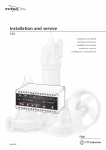
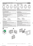
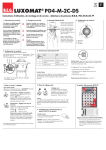
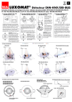
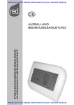
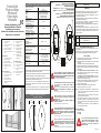
The kit includes:
N° 1 Transmitter photocell
N° 1 Receiver photocell
N° 1 Fastening fittings
N° 2 Caps for the lower hole
N° 2 Sheath connectors
N° 1 Installation and Use
Manual
Le
N°
N°
N°
N°
N°
N°
kit
1
1
1
2
2
1
est composé de:
Photocellule émetteur
Photocellule récepteur
Kit de fixation
Bouchons inférieur
Raccords pour gaine
Manuel d'Installation et
Utilisation
Fig. 02
Die Konfektion beinhaltet:
N° 1 Übertragungsgerät
fotozelle
N° 1 Empfänger fotozelle
N° 1 Montage-KIT
N° 2 Stöpsel für untere
Montagelòcher
N° 2 Anschlüsse für
Ummantelungen.
N° 1 Handbuch der
Installation und des
Gebrauchs
La confeciòn incluye:
N° 1 Fotocélula transmisora
N° 1 Fotocélula réceptora
N° 1 Kit fijaciòn
N° 2 Tapas para abertura
inferior
N° 2 Empalmes para vaina
N° 1 Manual de Uso e
Instalación
ATTENTION: Dés que l’installation est terminée, enlever le pontage
EINRICHTUNGSSCHALTDRAHT
ACHTUNG: Am Ende der Anlage den Schaltdraht abziehen
PUENTE CONTECTOR DE ALINEACIÓN
ATENCION: Terminada la instalación quitar la conección
Rx
Tx
900 Hz
Queste fotocellule dal design innovativo e moderno, creano una
barriera ottica a raggi infrarossi modulati invisibili ad occhio nudo.
La fotocellula è dotata di uno schermo antidisturbo per motori in
corrente continua o alternata.
Il fascio della fotocellula è stretto per evitare fenomeni di riflessione e
per rispondere alle norme vigenti.
I due componenti sono integrati in un contenitore dal piacevole
aspetto, di piccolo ingombro e di veloce installazione.
Non richiede centratura, può essere fissato a parete od a pilastro ed è
schermato ai raggi solari.
Normalmente poste ai lati dell'apertura, con proiettore da un lato e
ricevitore dall'altro, quando un oggetto od altro interrompe il fascio di
luce viene inviato un segnale all'unità di comando che blocca e/o
inverte il movimento.
12 / 24V ac dc + / - 10%
+
RX
-
+
50 mA Tx + Rx
TX
RELAY
-25°C ÷ +70°C
Max 0,5 A 24V
Con carico resistivo
Munies de charge résistive
With resistive load
Mit Ohmischer Belastung
Con carga resistiva
150 gr
+AC -AC
+AC -AC
12V dc
24V dc
24V dc
24V ac
2)
3)
4)
Cette portée peur se réduire jusqu’à 70% dans des conditions climatiques
particulièrement difficiles ou en cas d’un alignement imparfait.
ATTENZIONE
Este valor puede reducirse hasta el 70% en presencia de fenómenos
atmosféricos de importante intensidad o para una alineación imperfecta.
Dimensioni - Dimensions - DimensionsRaumbedarf - Medidas
35
55
PRIMA DI COLLEGARE LE FOTOCELLULE CONTROLLARE CHE LA
TENSIONE DI INGRESSO SIA UGUALE ALLA TENSIONE DI USCITA
DELLA CENTRALE. IN CASO DI ALIMENTAZIONE DIVERSA SPOSTARE I
PONTICELLI IN MANIERA ADEGUATA.
Le fotocellule sono predisposte per un'alimentazione a 24V dc.
5)
ATENTION
WARNING
Fig. 04
ACHTUNG
110
ATENCION
1-2
Descrizione
Alimentazione 12 o 24 Volt ac/dc
Contatto Relè N.C.
Alimentazione 12 o 24 Volt ac/dc.
COLLEGAMENTO MORSETTIERA (Fig.1)
Se necessario installare due coppie di fotocellule per avere una
doppia protezione.
Ricordarsi che non è giusto posizionare due ricevitori sullo stesso
pilastro: quindi invertire la posizione tra trasmettitore e ricevitore.
1)
12V dc
24V ac
Morsetti
1-2
3-4
RELAY
(*)
Questo valore può ridursi fino al 70% in presenza di fenomeni atmosferici di
notevole intensità o per un allineamento non perfetto.
Dieser Wert kann sich bei atmosphärischen Phänomenen von
bemerkenswerter Intensität um 70% reduzieren, auch bei nicht guter
Ausgerichtetheit.
40/60 cm
GENERALITA’
CENTERING JUMPER
WARNING: Once the installation has been done, remove the jumper
915 mm
This range can be reduced up to the 70% in case of particularity difficult
climatic conditions or if the alignment is not perfect.
Fig. 03
ITALIANO
PONTAGE D'ALIGNEMENT
TRAS
La confezione comprende:
N° 1 Trasmettitore per
fotocellula
N° 1 Ricevitore per fotocellula
N° 1 Kit fissaggio
N° 2 Tappi per foro inferiore
N° 2 Raccordi per guaina
N° 1 Manuale d’installazione e
d’uso
40 m (*)
Infrarosso modulato
Rayonnement infrarouge
Modular infra-red modulaire
Moduliertes infrarot
Infrarrojo modulato
PONTICELLO DI ALLINEAMENTO
ATTENZIONE: Ad installazione eseguita togliere il ponticello
24
Manuale d’Installazione e d’Uso
Manuel d'Installation et Utilisation
Installation and use manual
Handbuch der Installation und des Gebrauchs
Manual de Uso e Instalación
Portata - Porteé - Range
Leistung - Alcance
Segnale
Signal
Signal
Signal
Señal
Lunghezza d'onda
Longeur d’onde
Wavelenght - Wellenlänge
Lungitud de onda
Frequenza di modulazione
Fréquence de modulation
Frequency modulation
Modulations frequenz
Frequencia de modulaciòn
Alimentazione - Alimentation
Power supply - Speisung
Alimentacion
Assorbimento
Consommation à vide
Absorption
Liestungsaufnahme
Absorción
Temperatura d’esercizio
Température de fonctionnement
Working temperature
Betriebstemperatur
Temperatura de trabajo
Portata relè
Portée du relais
Relay range
Relaisleistung
Alcance relè
Peso - Poids - Weight
Gewicht - Peso
Fig. 01
24V 12V
Fotocellule
Photocellules
Photocell
Fotocelula
Fotozelle
Caratteristiche tecniche - Caracteristiques techniques
Technical features - Technische daten - Caracteristicas tecnicas
AVANT DE BRANCHER LE PHOTOCELLULES, VÉRIFIEZ QUE LA SORTIE
DE LA CENTRALE AIT LA MÊME TENSION D’ENTRÉE DES
PHOTOCELLULES.
DANS LE CAS CONTRAIRE DÉPLACEZ LES PONTAGES
D’ALIMENTATION (TRANSMETTEUR ET RÉCEPTEUR) DE FAÇON
ADÉQUATE.
Les photocellules sont disposés pour une alimentation à 24V dc.
BEFORE CONNECTING THE PHOTOCELLS, MAKE SURE THAT THE
OUTPUT VOLTAGE ON THE CONTROL PANEL IS THE SAME AS THE
PHOTOCELLS’ INPUT.
OTHERWISE PLACE THE VOLTAGE JUMPERS (TRANSMITTER AND
RECEIVER) ACCORDINGLY.
The photocells are set for 24V dc power supply.
VOR DEM ANSCHLIEßEN DER LICHTSCHRANKE ÜBERPRÜFEN, OB DIE
AUSGANGSSPANNUNG AUS DEM KRAFTWERK GLEICH DER
EINGANGASSPANNUNG DER LICHTSCHRANKE IST. ANDERNFALLS
SETZEN SIE DE JUMPER-KABEL (SENDER UND EMPFÄNGER) IN
ANGEMESSENER WEISE.
Die lichtschranke benoetigt 24V dc Spannungsversorgung.
ANTES DE CONECTAR LAS FOTOCÉLULAS VERIFICAR QUE EL
VOLTAJE DE SALIDA DE LA CENTRAL SEA IGUAL A LA TENSIÓN DE
ENTRADA DE LAS FOTOCÉLULAS. DE LO CONTRARIO, AJUSTAR LA
ALIMENTACIÓN (TRANSMISOR Y RECEPTOR) DE MANERA
APROPIADA.
Las fotocélulas están predispuestas a una alimentación 24V dc.
6)
INSTALLAZIONE
Per togliere il coperchio inserire per max 1 cm il cacciavite nella
parte inferiore e fare leva (aggancio a scatto)
Fissare la base alla parete od al pilastro con le due viti e/o tasselli
in dotazione.
La morsettiera si deve presentare nella parte inferiore.
Rispettare le altezze e la direzione fissando il Trasmettitore ed il
Ricevitore in posizione frontale, sullo stesso asse ed alla stessa
altezza. (Fig. 4)
• Per l'ingresso dei cavi in posizione posteriore: sfondare il
preforo sulla base ed inserire il tappino di chiusura nella parte
inferiore del coperchio. (Fig. 2)
• Per l'ingresso dei cavi in posizione inferiore: se con solo il
cavo, togliere il tappino; se con la guaina di protezione, utilizzare
l'apposito raccordo in dotazione. (Fig. 3)
Collegare i fili in morsettiera, tenendo presente che sui morsetti
3 e 4 del RX si ha, a fotocellula alimentata e centrata, un
contatto normalmente chiuso.
Alimentare sia il Trasmettitore che il Ricevitore come da
schema con tensione di 12 o 24 V ac / dc
Note: Se il posizionamento, l'allineamento ed i collegamenti sono
corretti, il led rosso del ricevitore sarà acceso, anche senza
coperchio ( max. 6/7 mt.)
Per portate superiori il led si accenderà solo inserendo il
coperchio (con lente incorporata)
Interrompendo il raggio tra TX ed RX, il led rosso si deve
spegnere, il contatto del relè deve diventare da normalmente
chiuso a normalmente aperto ed il contatto sui morsetti 3 e 4 si
deve aprire.
Inserire i coperchi di protezione a scatto, accertandosi che
siano aderenti ed in posizione.
PARTI DI RICAMBIO
Contenitore in plastica
Scheda TX
Scheda RX
ATTENZIONE
Per un uso proprio del prodotto e per escludere
ogni possibilità di danneggiamenti a persone
animali o cose, fare riferimento al foglio
“Generalità” che fa parte integrante del
presente manuale.
RF36_2012
FRANÇAIS
GENERALITE
Caractérisées par un design novateur et moderne, installées avec le
reste du matériel , elles créent une barrière de protection optique à
rayons infrarouges invisibles .
Les photocellules sont munies d'un philtre antiparasite pour éviter les
perturbations avec les moteurs que ce soit en courant continu ou
alternatif (norme EMC).
Le faisceau des photocellules répond aux normes en vigueur, il est
étroit pour éviter les phénomènes de réflexion .
Les deux cartes électroniques sont intégrés dans un boîtier très
esthétique, de petite dimension, et facile à installer. Installées sur les
piliers côtés extérieur , il y aura d'un côté la cellule émettrice et de
l'autre la cellule réceptrice, quand une personne, un véhicule, voir un
objet interrompt le faisceau entre les cellules un signal est envoyé à la
carte de gestion qui bloque et/ou inverse le mouvement du portail.
RX
Bornes
1-2
3-4
1-2
TX
GENERAL INSTRUCTIONS
With a modern and innovative design, matching the rest of the system,
they make an optical barrier by generating modulated infrared rays which
are invisible to the naked eye.
The photocell is equipped with an anti-interference shield for motors
running on a.c. or d.c.
The photocell beam is narrow to avoid reflection occurrences and to
match current regulations.
The two components are incorporated in a nice housing, of small size and
quick installation.
It doesn't need to be centered, it may be installed on a wall or on the pillar
and it is shielded from the sun rays.
They are usually on the opening sides, with the projector on one side and
the receiver on the other one, when an object or something else breaks in
the light beam, a signal is sent to the control unit which will stop and/or
invert the motion.
Description
Alimentation 12 ou 24 V ac/dc
Contact relais N.C.
RX
Alimentation 12 ou 24 V ac/dc
TX
CONNEXION (Fig.1)
S'il est nécessaire de monter deux paires de photocellules pour avoir
une double protection, le deuxième jeu devra être inversé par rapport
au premier, ne pas placer du même côté 2 cellules réceptrices ou 2
cellules émettrices il y a un risque de perturbation.
INSTALLATION
Pour enlever le couvercle il faut glisser un tournevis dans la partie
inférieure doucement
1) Faire levier pour d'éclipser l'ensemble.
2) Fixer l'embase du boîtier au mur ou au poteau avec 2 vis et
chevilles/ou les pattes en dotation (option).
Le bornier de connexion devant se trouver en bas.
3) Respecter les hauteurs et la direction lorsqu'on fixe la cellule TX (
émettrice) et la cellule RX (réceptrice) face à face, un bon
alignement est important. (Fig. 4)
4) • Pour le passage de câbles en saignée en partie basse, il faut
utiliser le pré-perçage et insérer le petit bouchon de fermeture
dans la partie inférieure du couvercle. (Fig. 2).
• Pour le passage des câbles en applique avec gaine dans la
partie inférieure, utiliser le raccord approprié en dotation. (Fig. 3)
5) Brancher les fils à partir des borniers de connexion en tenant
compte que sur les bornes 3 et 4 de la RX on a une fois la
photocellule alimentée et centrée, un contact normalement fermé.
6) Alimenter aussi bien l'émetteur que le Récepteur comme sur le
schéma avec une tension de 12 ou 24 V ac / dc selon votre
système.
Note:
Si lors de l'alimentation, l'alignement et les branchements
sont corrects, la led rouge de la cellule réceptrice (RX) sera
allumée, attention, sans le couvercle la portée maximum
sera de 6 à7m.
Pour une distance supérieure la led s'allumera uniquement
en mettant le couvercle. La portée max, avec de bonnes
conditions climatiques et son couvercle est de 40m.
En interrompant le rayon entre la cellule TX et RX, la led
rouge doit s'éteindre, le relais doit commuter, vous
l'entendrez ''cliquer'' le contact sur les bornes 3 et 4 s'ouvrira.
Insérer les couvercles de protection partie haute en premier
et appuyez pour les clipser correctement. Assurez vous de la
parfaite étanchéité de vos cellules en y ajoutant au niveau
des passages de câbles du joint type 'silicone''.
DEUTSCH
ENGLISH
Clamp
1- 2
3- 4
Description
Power supply 12 or 24 V ac/dc
Relais connection N.C.
1- 2
Power supply 12 or 24 V ac/dc
CONNECTION HOLDFAST (Fig. 1)
If there is the need to install two pairs of photocells to get a double
protection, remember that it is incorrect to install two receivers on the
same pillar, therefore switch the position between the projector and the
receiver.
1)
2)
3)
4)
5)
6)
INSTALLATION
To remove the cover insert the screwdriver for 1 cm. max. in the
lower part and lever it (click closing).
Fasten the base to the wall or to the pillar with 2 screws and/or
dowels on equipment. The terminal board must be installed on the
lower part.
Respect heights and direction fixing the TX and the RX in frontal
position and on the same axle and at the same height. (Fig. 4)
• For the cable entry in the back part break through the pre-hole
on the base and insert the closing little cap in the lower part of the
cover. (Fig. 2)
• For the cable entry in the lower position: if the cable is normal,
just put off the closing little cap, if the cable is with sheath for cable
protection, use the proper connector on equipement. (Fig. 3)
Connect the wires of the terminals boards taking into account that
on the terminals 3 and 4 of the RX we have, with a feeded and
centred photocell, a normally closed contact.
Power both the Transmitter and the Receiver, as per diagram, with
voltage of 12 or 24 V ac / dc
Note: If position, alignement and connections are correct, the red led of
the receiver will be on even without cover (max. 6/7 mt).
For higher capacities, the led will switch on only inserting the
cover.
Interrupting the ray between TX and RX, the red led must turn off,
the relay has to switch on and the contact on terminals 3 and 4
must open.
Insert the click protection covers making sure that they are
perfectly adhering and in position.
SPARE PARTS
Plastic box.
Diagram TX.
Diagram RX.
PARTIES DES RECHANGES
Boîtier en plastique
Carte TX
Carte RX
For a proper use of this product and to avoid any
damages to people, animals or things, refer to the
paper "General Instructions" that is part of this
manual.
ALLGEMEINES
Durch neues und modernes Design charakterisiert, das mit dem Rest der
Anlage harmoniert und eine optische Barriere aus modulierten
Infrarotstrahlen bildet, die mit bloßem Auge nicht sichtbar sind.
Die Lichtschranke besitzt eine Störungsabschirmung für Motoren mit
Gleichstrom und Wechselstrom.
Das Bündel der Lichtschranke ist so kreiert, daß es Reflexerscheinungen
verhindert und den herrschenden Normen entspricht.
Beide Komponenten sind in einem hübschen Behälter integriert, der nicht
sperrig ist und sich schnell installieren läßt.
Es bedarf keiner Zentrierung, sie kann an der Wand oder am Pfeiler
befestigt werden und ist gegen Sonneneinstrahlung abgesichert.
Normalerweise an den Seiten der Öffnung, mit dem Projektor auf einer
Seite und dem Empfänger auf der anderen, wenn ein Objekt oder etwas
anderes den in den Lichtkreis dringt, wird ein Signal an die
Kommandoeinheit geleitet, welche die Bewegung blockiert oder
invertiert.
RX
.
Klemm
1-2
3-4
1-2
TX
2)
3)
4)
5)
6)
Wenn die Positionierung, die Versorgung und die Spannung
korrekt sind, wird die rote LED des Empfängers auch ohne
Deckel angeschaltet sein ( max. 6 / 7 mt).
Bei schwereren Lasten stellt sich die LED nur ab, wenn der
Deckel abgesetzt ist.
Wird der Strahl zwischen TX und RX unterbrochen, muß die rote
LED sich abschalten, das Relais muß sich umstellen und der
Kontakt auf den Klemmen 3 und 4 sich öffnen.
Schutzdeckel einsetzen uns sichergehen, daß sie fest sitzen.
ERSATZTEILE
Kunststoffhalter
Karte TX.
Karte RX.
WARNING
ATENTION
Pour une bonne utilisation du produit et pour
éviter toute possibilité de dommages aux
personnes, aux animaux et aux biens, se référer
au paragraphe "Généralité" qui fait partie
intégrante du manuel d'installation.
ACHTUNG
RX
Speisung 12 und 24 V ac/dc
INSTALLATION
Um den Deckel abzunehmen, den Schraubenzieher in den unteren
Teil einführen und um max. 1 Zentimeter anheben
(Stotterkupplung).
Das Platte an der Wand oder am Pfeiler mit den beiden Schrauben
u./o. Dübel befestigen.
Das Klemmbrett muß am unteren Teil angebracht sein.
Höhen und Richtung respektieren, indem Übertragungsgerät und
Empänger in Frontalposition auf derselben Achse und auf
derselben Höhe befestigt werden. (Bild 4)
• Für den Eingang der Kabel in der hinteren Position das
vorgezeichnete Montageloch durchstoßen und den Stöpsel in den
unteren Teil vom Deckel einfügen . (Bild 2)
• Für den Eingang der Kabel: falls nur mit Kabel, den Stöpsel
abnehmen, falls mit Schutzummantelung, das dazu bestimmte
beigefügte Verbindungsstück verwenden. (Bild 3)
Die Drähte am Klemmbrett anschließen, dabei beachten Sie, daß
ein geschlossener Kontakt auf den Klemmen 4 und 5 des RX, bei
versorgter und zentrierter Lichtschranke, normalerweise besteht.
Ansender und Empfänger mit 12V oder 24V ac/dc Spannung
versorgen, wie auf dem Plan vorgesehen.
Note:
GENERALIDADES
Estas fotocélulas caracterizadas por un diseño innovador y moderno
hacen una barrera óptica con rayos infrarrojos modulados e
invisibles a simple vista.
La fotocelula está equipada con un filtro antiparásito para motores
de corriente continua o alterna.
El haz de la fotocélula es estrecho para evitar fenómenos de
reflexión y para ser conforme a las normativas vigentes.
Los dos componentes estan repuestos en agradables y pequeños
contenedores que facilitan la instalación.
No es necesario el centraje, pueden fijarse a la pared o al pillar y
están equipadas con un filtro para los rayos del sol.
Las fotocélulas se instalan normalmente a las extremidades de la
abertura, con el receptor por un lado y el emisor por el otro; cuando
un objeto u otra cosa se encuentra en el medio del haz de rayos,
viene enviado un siñal al cuadro electrónico que bloquea e/o invierte
la marcha.
Beschreibung
Speisung 12 und 24 V ac/dc
Anschluß Relé N.C.
ANSCHLÜSSE KLEMMBRETT (Fig 1)
Falls nötig, zwei Lichtschrankenpaare montieren, um einen doppelten
Schutz zu haben; dabei vermeiden, zwei Empfänger auf demselben
Pfeiler zu befestigen.
Aus diesem Gründen die Positionen von Projektor und Empfänger
invertieren.
1)
ESPAÑOL
TX
Borne
1-2
3-4
Descripcion
Alimentación 12 o 24 V ac/dc
Contacto Rele N.C.
1-2
Alimentación 12 o 24 V ac/dc
CONEXIÓN TABLERO DE BORNES (Fig.1)
Si es necesario instalar dos pares de fotocélulas para obtener una
protección doble y es importante recordarse de que es incorrecto
instalar dos receptores en el mismo pilar por esto es necesario
cambiar la posición del transmisor con la del receptor.
1)
2)
3)
4)
5)
6)
INSTALACIÓN
Para quitar la tapa insertar un destornillador por 1 cm en la
parte baja y presionar (enganche a presión).
Instalar la base al pillar o a la pared con los dos tornillos o
espigas. El tablero de bornes tiene que quedar en la parte
inferior.
Respectar las alturas y la dirección instalando el receptor y el
transmisor uno en frente al otro, en el mismo eje y a la misma
altura.(fig.4)
• Cables en posición posterior: Romper el agujero ya
perforado para insertar los cables por la parte posterior y luego
poner el pequeño tapón de cierre en la parte inferior de la tapa
(Fig.2).
• Cables en posición inferior: Para la inserción de los cables
en posición inferior se tiene que quitar el pequeño tapón, si se
tiene que insertar el cable simple;si se tiene que insertar el
cable protegido por una vaina se tiene que utilizar la unión en el
equipamento base (Fig.3)
Conectar los cables en el tablero de bornes, considerando que
en los bornes 3 y 4 del Receptor se obtiene, con la fotocélula
alimentada y centrada, un contacto normalmente cerrado.
Alimentar el Transmisor y el Receptor como en el esquema
con la tensión de 12 o 24 V ac /dc.
Note: Si la posición, la alineación y las conexiones están correctas, el
led rojo será encendido aun sin tapa ( max. 6/7 mt)
Para mayores capacidades el led se encenderá solo
insertando la tapa (con lente incorporada).
Interrumpiendo el rayo entre Tx y Rx el led rojo tiene que
apagarse, el Relè de cerrado se pone abierto y entonces el
contacto entre los bornes 3 Y 4 tiene que abrirse.
Insertar las tapas de protección a presión, haciendo cuidado
a que sean en adherencia y en posición.
REPUESTOS
Contenidor de plástico
Tarjeta Tx
Tarjeta Rx
Für eine optimale Nutzung des Produkts und um
jedmöglichen Schaden an Personen, Tieren und
Dingen auszuschließen, Siehe Blatt
"Allgemeines", das integrierender Bestandteil des
vorliegenden Handbuchs ist.
Para un uso apropriado del producto y para
excluir cualquiera posibilidad de daños a
personas animales o cosas consultar la hoja
"Generalidades” que forma parte del presente
manual.
ATENCION