1
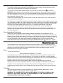
XPH Series 20V 20A
DC Power Supply
Operation Manual
M370044-01 Rev B
www.programmablepower.com
About AMETEK
AMETEK Programmable Power, Inc., a Division of AMETEK, Inc., is a global leader in the design
and manufacture of precision, programmable power supplies for R&D, test and measurement,
process control, power bus simulation and power conditioning applications across diverse
industrial segments. From bench top supplies to rack-mounted industrial power subsystems,
AMETEK Programmable Power is the proud manufacturer of Elgar, Sorensen, California
Instruments and Power Ten brand power supplies.
AMETEK, Inc. is a leading global manufacturer of electronic instruments and electromechanical
devices with annualized sales of $2.5 billion. The Company has over 11,000 colleagues working
at more than 80 manufacturing facilities and more than 80 sales and service centers in the United
States and around the world.
Trademarks
AMETEK is a registered trademark of AMETEK, Inc.
Other trademarks, registered trademarks, and product names are the property of their respective
owners and are used herein for identification purposes only.
Notice of Copyright
XPH Series 20V 20A DC Power Supply Operation Manual © 2007-2009 AMETEK Programmable
Power, Inc. All rights reserved.
Exclusion for Documentation
UNLESS SPECIFICALLY AGREED TO IN WRITING, AMETEK PROGRAMMABLE POWER, INC.
(“AMETEK”):
(a) MAKES NO WARRANTY AS TO THE ACCURACY, SUFFICIENCY OR SUITABILITY OF ANY
TECHNICAL OR OTHER INFORMATION PROVIDED IN ITS MANUALS OR OTHER
DOCUMENTATION.
(b) ASSUMES NO RESPONSIBILITY OR LIABILITY FOR LOSSES, DAMAGES, COSTS OR
EXPENSES, WHETHER SPECIAL, DIRECT, INDIRECT, CONSEQUENTIAL OR INCIDENTAL,
WHICH MIGHT ARISE OUT OF THE USE OF SUCH INFORMATION. THE USE OF ANY SUCH
INFORMATION WILL BE ENTIRELY AT THE USER’S RISK, AND
(c) REMINDS YOU THAT IF THIS MANUAL IS IN ANY LANGUAGE OTHER THAN ENGLISH,
ALTHOUGH STEPS HAVE BEEN TAKEN TO MAINTAIN THE ACCURACY OF THE
TRANSLATION, THE ACCURACY CANNOT BE GUARANTEED. APPROVED AMETEK CONTENT
IS CONTAINED WITH THE ENGLISH LANGUAGE VERSION, WHICH IS POSTED AT
WWW.PROGRAMMABLEPOWER.COM.
Date and Revision
January 2009 Revision B
Part Number
M370044-01
Contact Information
Telephone:
Fax:
Email:
Web:
800 733 5427 (toll free in North America)
858 450 0085 (direct)
858 458 0267
[email protected]
[email protected]
www.programmablepower.com
1
Introduction
The XPH 20-20 is an exceptionally compact and lightweight single output laboratory DC power
supply providing 0 to 20V at 0 to 20A.
The XPH 20-20 uses mixed−mode regulation technology which combines switch−mode
pre−regulation with linear post−regulation. Special techniques are used to maintain very high
efficiency whilst achieving noise levels that are close to that of a pure linear regulator.
Excellent line and load regulation are matched by low noise and good transient response. High
resolution controls allow accurate setting of voltage and current levels. Remote sense terminals
are provided so that good regulation can be maintained across remote loads at high currents.
The output operates in constant voltage or constant current mode with automatic cross-over and
mode indication. There is a DC output on−off switch.
The XPH series incorporates separate digital voltage and current meters on each output. The
meters use bright 14mm (0.56”) LED displays and have an update rate of 4 per second providing
near instantaneous response. Simultaneous metering of voltage and current provides accurate
information “at a glance” and avoids any possibility of misinterpretation. When the output switch is
set to “off”, the current limit setting is displayed enabling conditions to be set before the load is
connected.
The XPH series has been designed to meet the stringent requirements of the latest relevant IEC
standards for safety and EMC, including harmonics emissions. All outputs are intrinsically short
circuit proof, and are protected against external voltages and reverse currents.
Table of Contents
Introduction
2
Safety
4
EMC
5
Installation
6
Connections
6
Operation
7
Maintenance
8
Calibration
9
Instructions en Francais
11
Bedienungsanleitung auf Deutsch
15
Istruzioni in Italiano
20
Instrucciones en Español
25
Warranty Information
30
2
Specification
OUTPUT
Voltage Range:
0V to 20V minimum
Current Range:
0A to 20A minimum
Output Voltage Setting:
By coarse and fine controls.
Output Current Setting:
By single logarithmic control.
Operating Mode:
Constant voltage or constant current with automatic cross-over.
Output Switch:
Electronic. Preset voltage and current displayed when off.
Output Terminals:
4mm terminals on 19mm (0.75”) pitch.
Sensing:
Switchable between local and remote. Spring-loaded push
terminals for remote connection.
Output Protection:
Output will withstand up to 25V forward voltage.
Reverse protection by diode clamp for reverse currents up to 3A.
Over-temperature
Protection:
The output will be tripped off if a fault causes the internal
temperature to rise excessively.
Line Regulation:
Change in output for a 10% line change:
Constant voltage: <0.01% + 2mV
Constant current: <0.01% + 2mA
Load Regulation:
Change in output for any load change, remote sense connected:
Constant voltage: <0.01% + 5mV
Constant current: <0.05% + 2mA
Ripple & Noise
(20MHz bandwidth):
Typically <2mVrms, <20mV pk-pk, constant voltage mode.
Transient Response:
<0.5ms to within 50mV of set level for 90% load change.
Temperature Coefficient:
Typically <100ppm/°C
Status Indication:
Output on lamp. Constant current mode lamp.
METER SPECIFICATIONS
Meter Types:
Dual 4 digit meters with 14mm (0.56") LEDs. Reading rate 4 Hz.
Meter Resolutions:
10mV, 10mA
Meter Accuracies:
Voltage 0.3% of reading ± 2digit,
Current 0.6% of reading ± 2digit
GENERAL
AC Input:
Factory set for 110V-120VAC ±10% or 220V-240VAC ±10%,
50/60Hz. Installation Category II.
Power Consumption:
800VA max.
Operating Range:
+5ºC to +40ºC, 20% to 80% RH.
Storage Range:
−40ºC to + 70ºC.
Environmental:
Indoor use at altitudes up to 2000m, Pollution Degree 2.
Safety:
Complies with EN61010−1.
EMC:
Complies with EN61326.
Size:
140 x 160 x 320mm (WxHxD).
Weight:
3.6kg
3
Safety
This power supply is a Safety Class I instrument according to IEC classification and has been
designed to meet the requirements of EN61010-1 (Safety Requirements for Electrical Equipment
for Measurement, Control and Laboratory Use). It is an Installation Category II instrument
intended for operation from a normal single phase supply.
This instrument has been tested in accordance with EN61010-1 and has been supplied in a safe
condition. This instruction manual contains some information and warnings which have to be
followed by the user to ensure safe operation and to retain the instrument in a safe condition.
This instrument has been designed for indoor use in a Pollution Degree 2 environment in the
temperature range 5°C to 40°C, 20% - 80% RH (non-condensing). It may occasionally be
subjected to temperatures between +5° and -10°C without degradation of its safety. Do not
operate while condensation is present.
Use of this instrument in a manner not specified by these instructions may impair the safety
protection provided. Do not operate the instrument outside its rated supply voltages or
environmental range.
WARNING! THIS INSTRUMENT MUST BE EARTHED
Any interruption of the mains earth conductor inside or outside the instrument will make the
instrument dangerous. Intentional interruption is prohibited. The protective action must not be
negated by the use of an extension cord without a protective conductor.
When the instrument is connected to its supply, terminals may be live and opening the covers or
removal of parts (except those to which access can be gained by hand) is likely to expose live
parts. The apparatus shall be disconnected from all voltage sources before it is opened for any
adjustment, replacement, maintenance or repair. Capacitors inside the power supply may still be
charged even if the power supply has been disconnected from all voltage sources but will be
safely discharged about 10 minutes after switching off power.
Any adjustment, maintenance and repair of the opened instrument under voltage shall be avoided
as far as possible and, if inevitable, shall be carried out only by a skilled person who is aware of
the hazard involved.
If the instrument is clearly defective, has been subject to mechanical damage, excessive moisture
or chemical corrosion the safety protection may be impaired and the apparatus should be
withdrawn from use and returned for checking and repair.
Make sure that only fuses with the required rated current and of the specified type are used for
replacement. The use of makeshift fuses and the short-circuiting of fuse holders is prohibited.
Do not wet the instrument when cleaning it.
The following symbols are used on the instrument and in this manual:-
Earth (ground) terminal.
mains supply OFF.
l
mains supply ON.
alternating current (ac)
direct current (dc)
4
EMC
This instrument has been designed to meet the requirements of the EMC Directive 89/336/EEC.
Compliance was demonstrated by meeting the test limits of the following standards:
Emissions
EN61326 (1998) EMC product standard for Electrical Equipment for Measurement, Control and
Laboratory Use. Test limits used were:
a)
Radiated:
Class B
b)
Conducted: Class B
c)
Harmonics: EN61000-3-2 (2000) Class A; the instrument is Class A by product category.
Immunity
EN61326 (1998) EMC product standard for Electrical Equipment for Measurement, Control and
Laboratory Use.
Test methods, limits and performance achieved were:
a)
EN61000-4-2 (1995) Electrostatic Discharge : 4kV air, 4kV contact, Performance A.
b)
EN61000-4-3 (1997) Electromagnetic Field, 3V/m, 80% AM at 1kHz, Performance B.
c)
EN61000-4-11 (1994) Voltage Interrupt, 1 cycle, 100%, Performance B.
d)
EN61000-4-4 (1995) Fast Transient, 1kV peak (AC line), 0.5kV peak (DC Outputs),
Performance B.
e)
EN61000-4-5 (1995) Surge, 0.5kV (line to line), 1kV (line to ground), Performance B.
f)
EN61000-4-6 (1996) Conducted RF, 3V, 80% AM at 1kHz (AC line only; DC Output
connections <3m not tested), Performance B.
According to EN61326 the definitions of performance criteria are:
Performance criterion A: ‘During test normal performance within the specification limits.’
Performance criterion B: ‘During test, temporary degradation, or loss of function or
performance which is self-recovering’.
Performance criterion C: ‘During test, temporary degradation, or loss of function or
performance which requires operator intervention or system reset occurs.’
Where Performance B is stated it is because DC Output regulation may deviate beyond
Specification limits under the test conditions. However, the possible deviations are still small and
unlikely to be a problem in practice.
Note that if operation in a high RF field is unavoidable it is good practice to connect the PSU to
the target system using screened leads which have been passed (together) through an absorbing
ferrite sleeve fitted close to the PSU terminals.
Cautions
To ensure continued compliance with the EMC directive observe the following precautions:
a) after opening the case for any reason ensure that all signal and ground connections are
remade correctly and that case screws are correctly refitted and tightened.
b) In the event of part replacement becoming necessary, only use components of an identical
type, see the Service Manual.
5
Installation
Mains Operating Voltage
Check that the instrument operating voltage marked on the rear panel is suitable for the local
supply.
Mains Lead
Connect the instrument to the AC supply using the mains lead provided. Should a mains plug be
required for a different mains outlet socket, a suitably rated and approved mains lead set should
be used which is fitted with the required wall plug and an IEC60320 C13 connector for the
instrument end. To determine the minimum current rating of the lead-set for the intended AC
supply, refer to the power rating information on the equipment or in the Specification.
WARNING! THIS INSTRUMENT MUST BE EARTHED.
Any interruption of the mains earth conductor inside or outside the instrument will make the
instrument dangerous. Intentional interruption is prohibited.
Ventilation
The power supply is cooled by a low-speed fan which vents at the rear. Take care not to restrict
the air inlets at the side panels or the exit at the rear.
Connections
All connections are made from the front panel.
The load should be connected to the positive (red) and negative (black) terminals marked
OUTPUT.
Remote sense connections to the load, if required, are made from the positive (+) and
negative (−) SENSE terminals. Switch the LOCAL/REMOTE switch to REMOTE when remote
sensing is required. Switch back to LOCAL when remote sensing is not in use.
The terminal marked
6
is connected to the chassis and safety earth ground.
Operation
Setting Up the Output
With the POWER switch on (l) and the
output off the output voltage and current limit can be
accurately preset using the VOLTAGE and CURRENT controls; the left-hand meter shows the set
voltage and the right-hand meter shows the set maximum current.
When the
output switch is switched on, the ON lamp lights; the left-hand meter now shows
the actual voltage and the right-hand meter the actual load current.
Constant Voltage
The output voltage is adjusted using the coarse and fine VOLTAGE controls; the CURRENT
control sets the maximum current that can be supplied.
Constant Current
If the load resistance is low enough such that, at the output voltage set, a current greater than the
current limit setting would flow, the power supply will automatically move into constant current
operation. The current output is adjusted by the CURRENT control and the VOLTAGE controls
set the maximum voltage that can be generated.
The CC lamp lights to show constant current mode.
Instantaneous Current Output
The current limit control can be set to limit the continuous output current to levels down to 10mA.
However, in common with all precision bench power supplies, a capacitor is connected across the
output to maintain stability and good transient response. This capacitor charges to the output
voltage and short-circuiting of the output will produce a current pulse as the capacitor discharges
which is independent of the current limit setting.
Protection
The output has intrinsic short-circuit protection and is protected from reverse voltages by a diode;
the continuous reverse current must not exceed 3 Amps, although transients can be much higher.
Connection to the Load
The load should be connected to the positive (red) and negative (black) OUTPUT terminals. Both
are fully floating and either can be connected to ground.
Remote Sensing
The unit has a very low output impedance, but this is inevitably increased by the resistance of the
connecting leads. At high currents this can result in significant differences between the indicated
source voltage and the actual load voltage (two 20mΩ connecting leads will drop 0.2V at 5 Amps,
for instance). This problem can be minimised by using short, thick, connecting leads, but where
necessary it can be completely overcome by using the remote sense facility.
This requires the sense terminals to be connected to the output at the load instead of at the
source; insert wires into the spring-loaded SENSE terminals and connect directly to the load.
Switch the LOCAL/REMOTE switch to REMOTE. To avoid instability and transient response
problems, care must be taken to ensure good coupling between each output and sense lead.
This can be done either by twisting the leads together or by using coaxially screened cable
(sense through the inner). An electrolytic capacitor directly across the load connection point may
also be beneficial.
The voltage drop in each output lead must not exceed 0.5 Volts.
Switch the LOCAL/REMOTE switch back to LOCAL when remote sensing is not in use.
7
Series or Parallel Connection with Other Outputs
The outputs of the power supply are fully floating and may be used in series with other power
supply units to generate high DC voltages up to 300V DC.
The maximum permissible voltage between any terminal and earth ground (
) is 300VDC.
WARNING! Such voltages are exceedingly hazardous and great care should be taken to shield
the output terminals for such use. On no account should the output terminals be touched when
the unit is switched on under such use. All connections to the terminals must be made with the
power switched off on all units.
It should be noted that the unit can only source current and cannot sink it, thus units cannot be
series connected in anti-phase.
The unit can be connected in parallel with others to produce higher currents. Where several units
are connected in parallel, the output voltage will be equal to that of the unit with the highest output
voltage setting until the current drawn exceeds its current limit setting, upon which the output will
fall to that of the next highest setting, and so on. In constant current mode, units can be
connected in parallel to provide a current equal to the sum of the current limit settings.
Note that the output terminals are rated at 30A maximum; if several outputs are operated in
parallel to source higher currents than this the junction should be made at a separate point, not
one of the terminals.
Over-temperature Protection
Sensors on both the primary and secondary heatsinks will detect over-temperature due to
blocked air flow, fan failure or other circuit fault. Over-temperature will shut down the output (the
display will read 0 Volts and 0 Amps if the output is ON) though the output ON lamp will remain lit.
The output will remain shut down even after the heatsinks have cooled down. When the cause of
the over-temperature has been removed and the heatsinks have cooled to normal working
temperatures the output can be reset by turning the POWER switch off ( ) then on ( l ) again.
Maintenance
The Manufacturers or their agents overseas will provide repair for any unit developing a fault.
Where owner wish to undertake their own maintenance work, this should only be done by skilled
personnel in conjunction with the service manual which may be purchased directly from the
Manufacturers or their agents overseas.
Fuse
The correct fuse type is:
10 Amp 250V HBC time-lag(T), 5 x 20mm.
Note that the main function of the fuse is to make the instrument safe and limit damage in the
event of failure of one of the switching devices. If a fuse fails it is therefore very likely that the
replacement will also blow, because the supply has developed a fault; in such circumstances the
instrument will need to be returned to the manufacturer for service.
Make sure that only fuses of the required rated current and specified type are used for
replacement. The use of makeshift fuses and the short-circuiting of fuse-holders is prohibited.
To replace a fuse, first disconnect the instrument from the AC supply. Remove the 6 cover
securing screws and lift off the cover. Replace the fuse with one of the correct type and refit the
cover.
Cleaning
If the PSU requires cleaning use a cloth that is only lightly dampened with water or a mild
detergent. Polish the display window with a soft dry cloth.
WARNING! TO AVOID ELECTRIC SHOCK, OR DAMAGE TO THE PSU, NEVER ALLOW
WATER TO GET INSIDE THE CASE. TO AVOID DAMAGE TO THE CASE OR DISPLAY
WINDOW NEVER CLEAN WITH SOLVENTS.
8
Calibration
Allow at least 5 minutes warm-up before commencing calibration.
Access to Calibration Adjustments
All adjustments are on the front panel control board; all the trimmers are adjusted from the
reverse side of the board through holes in the board. To gain access to the board it is necessary
to remove the top cover.
WARNING!
When the instrument is connected to its supply the removal of covers is likely to expose live parts.
The instrument should be disconnected from all voltage sources before it is opened for any
adjustment, replacement, maintenance or repair. Capacitors inside the power supply may still be
charged even if the power supply has been disconnected from all voltage sources but will be
safely discharged about 5 minutes after switching off power.
Any adjustment, maintenance and repair of the opened instrument under voltage shall be avoided
as far as possible and, if inevitable, shall be carried out only by a skilled person who is aware of
the hazard involved.
Remove the 6 side screws and the front handle screw to release the top cover.
Control pcb calibration points (viewed from rear)
Equipment Required
A 5½ digit multimeter with better than 0.05% accuracy on dc volts and better than 0.1% accuracy
on dc current (to 10A); alternatively use a precision shunt for current measurement.
Rheostat or other high power load arrangement to provide up to 20A load at 20V.
1kΩ 1% 0.25W resistor.
9
Voltage Calibration
Set the sense switch to local. Connect the DMM (set to Volts) across the output. Set voltage and
current controls to minimum. Switch output ON (Check LED is on) and check for a reading of
00.00V ± 0.01V on the Volts display and DMM; check the Amps display reads 0.00 ± 0.01A.
Set voltage and current controls to maximum. Adjust VR5 (maximum output volts) for a reading of
20.15V to 20.25V on the DMM. Adjust VR6 (measured output volts) until the Volts display
matches the reading on the external DMM.
Switch output OFF. Adjust VR10 (preset volts) until the Volts display shows the previous reading.
Current Calibration
With output OFF, set voltage to 10.00V and connect the 1kΩ resistor across the output terminals.
With output ON, adjust VR11 until the Amps display shows 0.01. Remove 1kΩ resistor.
Switch output OFF. Set output voltage to nominally 2V. Set current limit control to 0.02A. Connect
the DMM (set to Amps) and load in series across the output. Switch output ON.
Adjust VR8 (offset compensation of current control error amp) for a reading of 0.020A
± .001A on the DMM. Check that the CC LED is ON and display reads 0.02.
Increase voltage controls and current control to maximum. Adjust load until the DMM reads
20.00A ± 0.02A. Adjust VR7 (measured output current) until the Amps display matches the DMM
reading.
Reduce load until the CC LED is ON. Adjust VR4 (maximum output current) until the Amps
display shows 20.2.
Voltage Regulation
Connect + sense to the + output terminal, connect – sense to the – output terminal. Select
Remote Sense.
Connect the DMM (set to Volts) across the sense terminals, no load, output ON.
Adjust voltage controls for a reading of 18.xxxx on the DMM; note exact reading.
Connect load of 9 to 9.9A to the output terminals and adjust VR9 (differential voltage gain) until
the external DMM matches the previous reading.
10
Sécurité
Ce système alimentation est un instrument de classe de sécurité 1 conforme à la classification
IEC et il a été conçu pour satisfaire aux exigences de la norme EN61010-1 (Exigences de
sécurité pour les équipements électriques de mesure, de contrôle et d'utilisation en laboratoire). Il
s'agit d'un instrument de Catégorie II d'installation devant être exploité depuis une alimentation
monophasée standard.
Cet instrument a été testé conformément à la norme EN61010-1 et il a été fourni en tout état de
sécurité. Ce manuel d'instructions contient des informations et des avertissements qui doivent
être suivis par l'utilisateur afin d'assurer un fonctionnement et un état en toute sécurité.
Cet instrument a été conçu pour être utilisé en intérieur, en environnement de pollution de
deuxième degré (Pollution degree 2) à des plages de températures de 5°C à 40°C, et à des taux
d'humidité compris entre 20% et 80% (sans condensation). Il peut être soumis de temps à autre à
des températures comprises entre +5°C et –10°C sans dégradation de sa sécurité. Ne pas
l'utiliser en conditions de condensation.
Toute utilisation de cet instrument de manière non spécifiée par ces instructions risque d'affecter
sa protection de sécurité. Ne pas utiliser l'instrument hors des plages de tension d'alimentation
nominale recommandées ni hors de ses tolérances d'environnement.
AVERTISSEMENT ! CET INSTRUMENT DOIT ETRE RELIE A LA TERRE
Toute interruption du conducteur de la terre du secteur à l'intérieur ou à l'extérieur de l'instrument
rendra l'instrument dangereux. Il est absolument interdit de priver intentionnellement l'instrument
de son branchement à la terre. La sécurité de l'instrument ne doit pas être annulée par l'utilisation
de rallonge sans conducteur de protection.
Lorsque l'instrument est relié au secteur, il est possible que les bornes soient sous tension :
l'ouverture des couvercles ou la dépose de pièces (à l'exception des pièces accessibles
manuellement) risque de mettre à découvert des pièces sous tension. L'instrument doit être
débranché du secteur et de toute source d'alimentationavant tout réglage, remplacement, travaux
d'entretien ou de réparations.
Les condensateurs qui se trouvent dans le bloc d'alimentation risquent de rester chargés, même
si le bloc d'alimentation a été déconnecté de toutes les sources d'alimentation, mais ils se
déchargeront en toute sécurité environ 10 minutes après extinction de l'alimentation.
Eviter dans la mesure du possible d'effectuer des réglages, travaux de réparations ou d'entretien
lorsque l'instrument ouvert est branché au secteur. Si cela s'avère toutefois indispensable, seul
un technicien compétent connaissant les risques encourus doit effectuer ce genre de travaux.
S'il est évident que l'instrument est défectueux, qu'il a été soumis à des dégâts mécaniques, à
une humidité excessive ou à une corrosion chimique, la protection de sécurité est affaiblie :
l'instrument doit être retiré de l'exploitation et renvoyé vérifications et de réparations.
Ne remplacer les fusibles que par des fusibles d'intensité nominale requise et du type spécifié. Il
est interdit d'utiliser des fusibles "maison" et de court-circuiter des porte-fusibles.
Ne jamais humidifier l'instrument lors du nettoyage.
Les symboles suivants se trouvent sur l'instrument, ainsi que dans ce manuel.
Borne de terre (masse)
l
alimentation secteur ON (allumée)
courant continu (c.c.)
alimentation secteur OFF (éteinte)
courant alternatif (c.a.)
11
Installation
Tension d’utilisation secteur
Vérifier que la tension opérationnelle de l'instrument indiquée sur le panneau arrière est
appropriée pour l'alimentation locale.
Câble secteur
Branchez cet instrument sur l’alimentation secteur en utilisant le câble d’alimentation fourni. Si la
prise murale requiert l’utilisation d’un câble d’alimentation différent, un câble approprié et
approuvé, qui possède une fiche correspondante à la prise murale et un connecteur d’instrument
IEC60320 C13, doit être utilisé. Pour vérifier la tension nominale du câble d’alimentation en
fonction de la prise secteur, consultez les informations de puissance nominale sur l’équipement
ou dans Caractérstiques.
AVERTISSEMENT! CET INSTRUMENT DOIT ETRE RELIE A LA TERRE
Toute interruption du conducteur de terre secteur à l'intérieur ou à l'extérieur de l'instrument
rendra l'instrument dangereux. Il est absolument interdit d'effectuer une interruption à dessein.
Ventilation
L'unité d'alimentation est refroidie par un ventilateur à faible vitesse de rotation qui aère l'arrière.
Prendre soin de ne jamais obstruer les fentes d'aération des panneaux latéraux ni l'arrière de
l'unité
Connexions
Toutes les connexions sont effectuées au panneau avant.
Relier la charge aux bornes positive (rouge) et négative (noire) marquées OUTPUT (Sortie).
Effectuer des connexions de télédétection à la charge, le cas échéant, des bornes de détection
(SENSE) positive (+) et négative (−). Placer le commutateur LOCAL/REMOTE en position
REMOTE lorsque la détection distante est requise. Placer le commutateur en position LOCAL
lorsque cette détection distante n’est pas utilisée.
La borne désignée
12
est reliée au châssis et à la terre de protection.
Fonctionnement
Réglage de la sortie
L’interrupteur POWER (alimentation) sur (l) et la sortie
éteinte, il est possible de régler avec
précision la limite de tension et de courant de sortie au moyen des commandes VOLTAGE
(Tension) et CURRENT (Courant); l’appareil de mesure gauche indique la tension réglée et
l’appareil droit le courant maximum réglé.
Lorsque le commutateur de sortie
est sur marche, le témoin ON (Marche) s’allume; l’appareil
de mesure gauche indique alors la tension véritable et l’appareil droit le courant de charge
véritable.
Tension constante
Les commandes VOLTAGE de réglage grossier et de précision permettent d’ajuster la tension de
sortie; la commande CURRENT règle le courant maximum qui peut être fourni.
Courant constant
Si la résistance de charge est suffisamment basse qu’un courant supérieur au réglage de limite
de courant puisse passer pour la tension de sortie réglée, l’alimentation passera
automatiquement en mode de fonctionnement de courant constant. La commande CURRENT
ajuste le courant de sortie et les commandes VOLTAGE règlent la tension maximale qui peut être
engendrée. Le témoin CC s’allume pour indiquer le mode de courant constant.
Sortie de courant instantanée
Il est possible de régler la commande de limite de courant pour limiter le courant de sortie continu
à des niveaux aussi bas que 10 mA. Toutefois, ainsi que c’est le cas de toutes les alimentations
de précision sur banc, un condensateur est relié aux bornes de la sortie, afin de maintenir la
stabilité, ainsi qu’une bonne réponse transitoire. Ce condensateur se charge jusqu’à la tension de
sortie, et le court-circuitage de la sortie produira une impulsion de courant, lors du déchargement
du condensateur indépendamment du réglage de limite de courant.
Protection
La sortie dispose d’une protection intrinsèque contre les courts-circuits et elle est protégée contre
la tension inverse par une diode; le courant inverse continu ne doit pas dépasser 3 A, bien qu’il
soit possible que l’intensité des transitoires soit nettement supérieure.
Connexion à la charge
Relier la charge aux bornes de sortie positive (rouge) et négative (noire). Les deux bornes sont
entièrement flottantes et il est possible de relier chacune à la terre.
Télédétection
Le bloc a une impédance de sortie très réduite, mais la résistance des câbles de raccordement
l'augmente automatiquement. En cas de courants élevés, ceci peut entraîner des différences
importantes entre la tension de source indiquée et la tension de charge véritable (par exemple,
deux câbles de raccordement de 20 mΩ entraîneront une chute de 0,2 V à une intensité de 5A). Il
est possible de réduire ce problème au minimum au moyen de câbles de raccordement courts et
épais et, le cas échéant, le résoudre entièrement au moyen de l'option de télédétection.
Ceci nécessite la connexion des bornes de détection à la sortie de la charge plutôt qu'à la
source ; insérer les fils dans les bornes à ressort SENSE et connecter directement à la charge.
Placer le commutateur LOCAL/REMOTE en position REMOTE. S'assurer qu'il y a un bon
couplage entre chaque fil de sortie et fil de détection pour éviter tout problème d'instabilité et de
réponse transitoire. On peut y parvenir soit par torsion des fils soit par utilisation de câble blindé
coaxialement (détection par le conducteur interne). Il peut s'avérer utile de relier directement un
condensateur électrolytique au point de connexion de charge.
La chute de tension de chaque fil de sortie ne doit pas dépasser 0,5 V.
Placer le commutateur LOCAL/REMOTE en position LOCAL lorsque la détection distante n’est
pas utilisée.
13
Connexion en série ou en parallèle avec d’autres sorties
Les sorties de l’alimentation sont entièrement flottantes et elles peuvent être utilisées en série
avec d’autres blocs d’alimentation, afin de produire des tensions c.c. jusqu’à 300 V c.c.
La tension maximale admissible entre une borne et la terre ( ) est de 300 V c.c.
AVERTISSEMENT! Des tensions de ce genre sont extrêmement dangereuses et il faut prendre
toutes les précautions d’usage pour protéger les bornes de sortie en conséquence. Ne jamais
toucher les bornes de sortie lorsque le bloc est allumé pour ces applications. Toutes les
connexions des bornes doivent être effectuées lorsque tous les blocs sont éteints.
Il faut noter que le bloc peut uniquement recevoir du courant, mais non le consommer, de sorte
qu’il n’est pas possible de mettre en opposition de phase les blocs reliés en série.
Il est possible de relier le bloc en parallèle avec d’autres, afin de produire des courants de haute
intensité. Lorsque plusieurs blocs sont reliés en parallèle, la tension de sortie doit être égale à
celle du bloc de réglage de tension de sortie le plus élevé, jusqu’à ce que le courant consommé
dépasse le réglage de limite de courant, auquel cas la sortie descend à celle du réglage le plus
haut suivant, etc. En mode de courant constant, les blocs peuvent être reliés en parallèle, afin de
donner un courant égal à la somme des réglages de limite de courant.
Il faut noter que la tension nominale maximale des bornes de sortie est de 30 A; si plusieurs
sorties sont utilisées en parallèle avec la source avec des courants plus élevés, effecteur une
jonction à un point séparé, et non à des bornes.
Protection contre la surchauffe
Des sondes situées à la fois sur les dissipateurs thermiques primaire et secondaire détecteront
les surchauffes dues à l'obstruction de la circulation de l'air, à une panne de ventilateur ou toute
autre défaillance de circuit. Toute surchauffe éteint la sortie (l'écran affiche 0 Volts et 0 Amps si
la sortie est réglée sur ON) mais le témoin lumineux ON de la sortie reste allumé. La sortie reste
fermée même après refroidissement des dissipateurs thermiques. Une fois la cause de la
surchauffe éliminée et les dissipateurs thermiques à température normale d'exploitation, la
sortie peut être remise à zéro en actionnant l'interrupteur d'alimentation sur arrêt ( ) puis sur
marche ( l ).
Maintenance
Le Constructeur ou ses agents à l'étranger répareront tout bloc qui tombe en panne. Si le
propriétaire de l'appareil décide d'effectuer lui-même la maintenance, ceci doit uniquement être
effectué par un personnel spécialisé qui doit se référer au manuel d’entretien que l'on peut se
procurer directement auprès du Constructeur ou de ses agents à l'étranger.
Fusible
Type de fusible correct:
10 A 250 V HBC temporisé (T), 5 x 20 mm.
Il faut noter que l’objet principal de ce fusible est de rendre l’instrument non dangereux et de
limiter les dégâts en cas de panne d’un des dispositifs de commutation. En cas de panne d’un
fusible, il est très probable que le fusible de rechange sautera également, étant donné que
l’alimentation est probablement défectueuse; lorsque c’est le cas, il faudra renvoyer l’instrument
chez le constructeur en vue de réparations.
Uniquement remplacer les fusibles par des fusibles d'intensité nominale requise et de type
spécifié. Il est interdit d'utiliser des fusibles bricolés et de court-circuiter des porte-fusibles.
Pour remplacer un fusible, commencer par débrancher l’instrument de l’alimentation c.a. Enlever
les 6 vis d’immobilisation du couvercle, puis enlever le couvercle. Remplacer le fusible par un
autre de type correct, puis remettre le couvercle.
Nettoyage
S'il faut nettoyer le bloc d'alimentation, utiliser un chiffon légèrement imbibé d'eau ou d'un
détergent doux. Nettoyer le cadran d'affichage au moyen d'un chiffon sec et doux.
AVERTISSEMENT! EMPECHER TOUTE INTRODUCTION D'EAU DANS LE BOITIER AFIN D'EVITER
TOUT CHOC ELECTRIQUE ET DEGATS AU BLOC D'ALIMENTATION. NE JAMAIS UTILISER DE
DISSOLVANTS POUR NETTOYER LE BLOC, AFIN D'EVITER D'ENDOMMAGER LE BOITIER OU LE
CADRAN D’AFFICHAGE.
14
Sicherheit
Diese Stromversorgung wurde nach der Sicherheitsklasse (Schutzart) I der IEC-Klassifikation und
gemäß den europäischen Vorschriften EN61010-1 (Sicherheitsvorschriften für Elektrische Meß-,
Steuer, Regel- und Laboranlagen) entwickelt. Es handelt sich um ein Gerät der
Installationskategorie II, das für den Betrieb von einer normalen einphasigen Versorgung
vorgesehen ist.
Das Gerät wurde gemäß den Vorschriften EN61010-1 geprüft und wurde in sicherem Zustand
geliefert. Die vorliegende Anleitung enthält vom Benutzer zu beachtende Informationen und
Warnungen, die den sicheren Betrieb und den sicheren Zustand des Gerätes gewährleisten.
Dieses Gerät ist für den Betrieb in Innenräumen der Umgebungsklass 2 , für einen
Temperaturbereich von 5° C bis 40° C und 20 - 80 % relative Feuchtigkeit (nicht kondensierend)
vorgesehen. Gelegentlich kann es Temperaturen zwischen +5° und –10°C ausgesetzt sein, ohne
daß seine Sicherheit dadurch beeinträchtigt wird. Betreiben Sie das Gerät jedoch auf keinen Fall,
solange Kondensation vorhanden ist.
Ein Einsatz dieses Geräts in einer Weise, die für diese Anlage nicht vorgesehen ist, kann die
vorgesehene Sicherheit beeinträchtigen. Auf keinen Fall das Gerät außerhalb der angegebenen
Nennversorgungsspannungen oder Umgebungsbedingungen betreiben.
WARNUNG! - DIESES GERÄT MUSS GEERDET WERDEN!
Jede Unterbrechung des Netzschutzleiters innerhalb oder außerhalb des Geräts macht das Gerät
gefährlich. Eine absichtliche Unterbrechung ist verboten. Die Schutzwirkung darf durch
Verwendung eines Verlängerungskabels ohne Schutzleiter nicht aufgehoben werden.
Ist das Gerät an die elektrische Versorgung angeschlossen, so können die Klemmen unter
Spannung stehen, was bedeutet, daß beim Entfernen von Verkleidungs- oder sonstigen Teilen
(mit Ausnahme der Teile, zu denen Zugang mit der Hand möglich ist) höchstwahrscheinlich
spannungsführende Teile bloßgelegt weden. Vor jeglichem Öffnen des Geräts zu Nachstell-,
Auswechsel-, Wartungs- oder Reparaturzwecken, Gerät stets von sämtlichen Spannungsquellen
abklemmen.
Kondensatoren in der Stromversorgung können auch noch nach Abschalten sämtlicher
Stromversorgung Spannung führen, sie entladen sich jedoch innerhalb von etwa 10 Minuten nach
Spannungsabschaltung.
Jegliche Nachstellung, Wartung und Reparatur am geöffneten, unter Spannung stehenden Gerät,
ist nach Möglichkeit zu vermeiden. Falls unvermeidlich, sollten solche Arbeiten nur von
qualifiziertem Personal ausgeführt werden, das sich der Gefahren bewußt ist.
Ist das Gerät eindeutig fehlberbehaftet, bzw. wurde es mechanisch beschädigt, übermäßiger
Feuchtigkeit oder chemischer Korrosion ausgesetzt, so können die Schutzeinrichtungen
beeinträchtigt sein, weshalb das Gerät aus dem Verkehr zurückgezogen und zur Überprüfung
und Reparatur eingesandt werden sollte.
Sicherstellen, daß nur Sicherungen der vorgeschriebenen Stromstärke und des vorgesehenen
Typs als Ersatz verwendet werden. Provisorische “Sicherungen” und der Kurzschluß von
Sicherungshaltern ist verboten.
Beim Reinigen darauf achten, daß das Gerät nicht naß wird.
Am Gerät werden folgende Symbole verwendet:
Erdungsklemme
l
Netz ON (ein)
Gleichstrom
Netz OFF (aus)
Wechselstrom
15
Installation
Netzbetriebsspannung
Sicherstellen, daß die auf der Geräterückwand angegebene Betriebsspannung mit der
Versorgungsspannung am Ort übereinstimmt.
Netzkabel
Schließen Sie das Instrument unter Verwendung des mitgelieferten Netzkabels an die
Wechselstromversorgung an. Falls ein Netzstecker für eine unterschiedliche Steckdose
erforderlich ist, muss ein geeigneter zugelassener Netzkabelsatz verwendet werden, der mit der
erforderlichen Steckdose und einem IEC60320 C13-Stecker für das Instrument versehen ist. Die
minimale Nennstromstärke des Kabelsatzes für die beabsichtigte Wechselstromversorgung ist
den Nennleistungsangaben auf dem Gerät oder den Spezifikationen zu entnehmen.
WARNUNG! DIESES GERÄT MUSS GEERDET WERDEN!
Jede Unterbrechung des Netzschutzleiters innerhalb oder außerhalb des Gerätes macht das
Gerät gefährlich. Eine absichtliche Unterbrechung ist verboten.
Belüftung
Die Stromversorgung wird von einem Ventilator gekühlt, der Luft aus der Geräterückseite bläst.
Es ist darauf zu achten, dass die Lufteinlassöffnungen an den Seitenwänden und die
Auslassöffnung auf der Rückseite frei bleiben.
Anschlüsse
Sämtliche Anschlüsse erfolgen von der Fronttafel aus.
Der Verbraucher sollte an die mit AUSGANG (OUTPUT) markierte positive (rot) und negative
(schwarz) markierte Klemme angeschlossen werden.
Istwert-Fernerfassungs-Anschlüsse zum Verbraucher erfolgen, falls erforderlich, über die
positive (+) und negative (−) Fernerfassungsklemme (SENSE). Den Fernbedienungsschalter
(LOCAL/REMOTE) auf Fernbedienung (REMOTE) stellen, wenn eine Istwert-Fernerfassung
gewünscht wird. Wenn die Istwert-Fernerfassung nicht benutzt wird, auf Ortsbedienung (LOCAL)
zurückstellen.
Die mit dem Symbol
verbunden.
16
gekennzeichnete Klemme ist mit dem Chassis und der Schutzerde
Betrieb
Einstellung des Ausgangs
Bei eingeschaltetem POWER-Schalter (Netz I) und ausgeschaltetem Ausgang
läßt sich die
Ausgangsspannung und Strombegrenzung mit Hilfe der Knöpfe VOLTAGE (Spannung) und
CURRENT (Strom) genau voreinstellen. Die linke Anzeige zeigt die eingestellte Spannung und
die rechte den eingestellten Maximalstrom an.
Wenn der Ausgangsschalter
eingeschaltet wird, leuchtet die ON (Ein)-Leuchte auf. Jetzt
wird auf der linken Anzeige die Istspannung und an der rechten Anzeige der Ist-Laststrom
angezeigt.
Konstantspannung
Die Ausgangsspannung wird mittels der Grob- (coarse) und Feindrehknöpfe (fine) von VOLTAGE
reguliert. Mit dem Knopf CURRENT (Strom) wird der Maximalstrom eingestellt, der zur Verfügung
gestellt werden kann.
Konstantstrom
Ist der Belastungswiderstand ausreichend niedrig, daß bei der eingestellten Ausgangsspannung
ein Strom fließen würde, der größer wäre als die eingestellte Strombegrenzung, so schaltet die
Stromversorgung automatisch auf konstanten Strombetrieb. Der Stromausgang wird mit dem
Knopf CURRENT eingestellt und die maximal generierbare Spannung mit dem Knopf VOLTAGE.
Die CC-Leuchte leuchtet bei eingeschaltetem Konstantstrommodus auf.
Augenblickstromausgang
Mit der Strombegrenzung kann der kontinuierliche Ausgangsstrom bis auf 10 mA begrenzt
werden. Wie bei allen Präzisions-Stromversorgungs-Tischgeräten ist der Ausgang zur
Aufrechterhaltung der Stabilität und zwecks gutem Einschwingverhalten mit einem Kondensator
versehen. Der Kondensator wird bis zur Höhe der Ausgangsspannung aufgeladen. Ein
Kurzschließen des Ausgangs bewirkt beim Entladen des Kondensators einen Stromimpuls, der
von der Strombegrenzungseinstellung unabhängig erfolgt.
Schutzvorrichtungen
Der Ausgang ist mit einem eigenen Kurzschlußschutz versehen und mittels Diode vor
Umkehrspannungen geschützt. Kontinuierlicher Umkehrstrom darf 3 Amp nicht überschreiten.
Transiente Ströme können jedoch wesentlich höher liegen.
Verbraucheranschluß
Der Verbraucher ist an die positive (rote) und negative (schwarze) Ausgangsklemme
anzuschließen. Bei beiden Anschlüssen handelt es sich um vollkommen potentialfreie, die jeweils
geerdet werden können.
Istwert-Fernerfassung
Die Ausgangsimpedanz ist bei dieser Einheit sehr niedrig, wird aber zwangsläufig durch den
Widerstand der Verbindungsleitungen erhöht. Bei hohen Stromstärken können sich hieraus
erhebliche Unterschiede zwischen der angezeigten Quellenspannung und der tatsächlichen
Lastspannung ergeben (bei zwei 20-mΩ-Anschlussleitungen ergibt sich beispielsweise ein
Spannungsabfall von 0,2V bei 5A). Dieses Problem kann durch die Verwendung einer kurzen
Verbindungsleitung mit großer Drahtstärke minimiert und, falls erforderlich, durch die Verwendung
der Einrichtung zur Istwert-Fernerfassung sogar ganz ausgeschaltet werden.
Zu diesem Zweck müssen die SENSE-Klemmen mit dem Ausgang des Verbrauchers statt mit
dem Ausgang der Quelle verbunden werden. Die Leitungen werden in die federbelasteten
SENSE-Klemmen eingeführt und direkt an den Verbraucher angeschlossen. Der
Fernbedienungsschalter (LOCAL/REMOTE) wird auf Fernbedienung (REMOTE) gestellt. Um
Probleme bezüglich der Stabilität und des Einschwingverhaltens zu vermeiden, ist sorgfältig
darauf zu achten, dass eine gute Kopplung zwischen dem jeweiligen Ausgang und der
17
Abtastleitung gegeben ist. Dies lässt sich auf zweierlei Arten erreichen: entweder indem die
Leitungen miteinander verdrillt werden oder indem ein koaxial geschirmtes Kabel (Abtastung über
den Innerleiter) verwendet wird. Auch ein Elektrolytkondensator direkt am Lastanschlusspunkt
kann hier von Nutzen sein.
Der Spannungsabfall darf bei keiner Ausgangsleitung mehr als 0.5 Volt betragen.
Wenn die Istwert-Fernerfassung nicht benutzt wird, ist der Fernbedienungsschalter
(LOCAL/REMOTE) auf Ortsbedienung (LOCAL) zurückzustellen.
Reihen- und Parallelschaltung mit anderen Ausgängen
Da der Ausgang des Netzteils vollständig potentialfrei ist, kann er mit anderen Netzgeräten zur
Erzeugung hoher Gleichspannungen bis maximal 300V in Reihe geschaltet werden.
Die maximal zulässige Spannung zwischen einer beliebigen Klemme und Erde (
V Gleichspannung.
) beträgt 300
WARNUNG! Spannungen in dieser Größenordnung sind überaus gefährlich. Bei einer solchen
Einsatzweise sollten die Ausgangsklemmen mit größter Sorgfalt abgeschirmt werden. Unter
diesen Bedingungen dürfen die Ausgangsklemmen keinesfalls berührt werden, wenn das Gerät
eingeschaltet ist. Wann immer Verbindungen mit den Klemmen hergestellt werden, müssen
sämtliche Geräte ausgeschaltet sein.
Zu beachten ist dabei, daß das Gerät ausschließlich stromliefernd, nicht aber stromziehend
arbeiten kann, und daß die Geräte daher nicht gegenphasig in Reihe geschaltet werden können.
Das Gerät kann zur Erzeugung einer höheren Stromabgabe mit anderen Geräten parallel zu
diesen geschaltet werden. Wenn mehrere Geräte parallel geschaltet werden, entspricht die
Ausgangsspannung der Ausgangsspannung des Geräts, bei dem der Einstellwert für die
Ausgangsspannung am höchsten ist, bis die Stromaufnahme den bei diesem Gerät eingestellten
Grenzwert überschreitet, woraufhin der Ausgang auf die zweilhöchste Einstellung abfällt, und so
weiter. Im Konstantstrombetrieb können Geräte parallel geschaltet werden, wodurch sich eine
Stromabgabe erreichen läßt, die der Summe der Einstellwerte für die Strombegrenzung
entspricht.
Zu beachten ist, daß die Ausgangsklemmen für maximal 30 A vorgesehen sind. Werden mehrere
Ausgänge parallel betrieben, um höhere Ströme als diesen zu liefern, so sollte die Verbindung an
einer getrennten Stelle vorgenommen werden, nicht an einer der Klemmen.
Übertemperaturschutz
Sensoren in den Primär- und Sekundärkühlkörpern nehmen Übertemperaturen aufgrund eines
blockierten Luftstroms, eines Ventilatorausfalls oder anderen Fehlern im Stromkreis wahr. Bei
Übertemperatur wird der Ausgang abgeschaltet (es werden 0 Volt und 0 Ampere angezeigt, wenn
der Ausgang eingeschaltet (ON) ist), aber die Kontrollleuchte "output ON" leuchtet weiter.
Der Ausgang bleibt abgeschaltet, auch nachdem sich die Kühlkörper abgekühlt haben. Wenn der
Grund für die Übertemperatur gefunden und behoben wurde und sich die Kühlkörper auf normale
Arbeitstemperatur abgekühlt haben, kann der Ausgang wieder eingestellt werden, indem der
Stromschalter aus- ( ) und wieder eingeschaltet ( l ) wird.
18
Wartung
Die Hersteller bzw. deren Vertretungen im Ausland bieten die Reparatur von Geräten an, bei
denen eine Störung aufgetreten ist. Wenn der Eigentümer die Wartungsarbeiten selbst
durchführen möchte, hat er dafür Sorge zu tragen, daß diese Arbeiten ausschließlich von
entsprechend qualifiziertem Personal und gemäß Wartungshandbuch ausgeführt werden, das
direkt von den Herstellern oder deren Vertretungen im Ausland bezogen werden kann.
Sicherung
Korrekter Sicherungstyp:
Träge Hochleistungssicherung (T) 10 Amp, 250 V, 5 x 20 mm
Beachten Sie bitte, daß die Hauptfunktion der Sicherung der Schutz von Personen sowie
Geräteteilen ist bzw. die Begrenzung solcher Schäden im Falle von Störungen an den
Schaltgeräten. Brennt eine Sicherung durch, so ist es höchst wahrscheinlich, daß auch ihr Ersatz
durchbrennt, weil eine Störung im Gerät vorliegt. In einem solchen Falle ist es erforderlich, daß
das Gerät vom Hersteller repariert wird.
Achten Sie darauf, daß nur Sicherungen der vorgeschriebenen Stromstärke und des
angegebenen Typs als Ersatzsicherungen verwendet werden. Die Verwendung von
Behelfssicherungen und das Kurzschließen von Sicherungshaltern ist verboten.
Zum Auswechseln einer Sicherung zuerst das Gerät von seiner Wechselstromversorgung
trennen. Dann die 6 Befestigungsschrauben des Gehäuses entfernen und danach das Gehäuse
abheben. Sicherung durch eine korrekte Ersatzsicherung ersetzen und Gehäuse wieder
montieren.
Reinigung
Falls die Stromversorgung der Reinigung bedarf, einen mit Wasser oder einem milden Detergens
angefeuchteten Lappen benutzen. Anzeigefenster mit einem weichen, trockenen Lappen
polieren.
WARNUNG! ZUR VERMEIDUNG EINES ELEKTRISCHEN SCHLAGS BZW. BESCHÄDIGUNG DER
STROMVERSORGUNGSEINHEIT, DAFÜR SORGEN, DASS KEIN WASSER INS GEHÄUSE
EINDRINGT. UM SCHADEN AM GEHÄUSE BZW. AM ANZEIGEFENSTER ZU VERMEIDEN, KEINE
LÖSUNGSMITTEL ZUR REINIGUNG VERWENDEN!
19
Sicurezza
Questo alimentatore appartiene alla Categoria di Sicurezza 1 secondo la classifica IEC ed è stato
progettato in modo da soddisfare i criteri EN61010-1 (requisiti di Sicurezza per Apparecchiature
di misura, controllo e per uso in laboratorio). È uno strumento di Categoria II di installazione e
inteso per funzionamento con un’alimentazione normale monofase.
Questo strumento ha superato le prove previste da EN61010-1 e viene fornito in uno stato di
sicurezza normale. Questo manuale contiene informazioni e avvertenze che devono essere
seguite per assicurarsi di un’operazione sicura e mantenere lo strumento in condizioni di
sicurezza.
Questo strumento è progettato per uso all’interno e in un ambiente d’inquinamento Grado 2, entro
la gamma di temperatura da 5°C a 40°C con umidità relativa (non condensante) di
20% - 80%. Può occasionalmente essere assoggettato a temperature fra +5°C e –10°C senza
comprometterne la sicurezza. Non usare in presenza di condensazione.
L’uso dello strumento in maniera non conforme a quanto specificato in queste istruzioni potrebbe
pregiudicare la protezione di cui è dotato. Non usare lo strumento per misurare tensioni al di
sopra dei valori nominali o in condizioni ambientali al di fuori di quelle specificate.
ATTENZIONE! QUESTO STRUMENTO DEVE ESSERE COLLEGATO A TERRA
Una qualsiasi interruzione sia interna che esterna del collegamento a terra lo rende pericoloso. È
proibito interrompere questo collegamento deliberatamente. La protezione non deve essere
negata attraverso l’uso di un cavo di prolunga privo del filo di collegamento a terra.
Quando lo strumento è alimentato, alcuni morsetti sono sotto tensione e l’apertura dei coperchi o
la rimozione di parti (eccetto quei componenti accessibili senza l’uso di attrezzi) può lasciare
scoperti dei morsetti sotto tensione. L’apparecchiatura deve essere staccata da tutte le sorgenti
di tensione prima di aprirla per regolazioni, manutenzione o riparazioni.
I condensatori collegati all’alimentazione interna possono essere carichi anche dopo aver
staccato l’alimentazione ma si scaricano in circa 10 minuti dopo aver levato la corrente.
È consigliabile evitare, per quanto possibile, qualsiasi operazione di regolazione e di riparazione
dello strumento sotto tensione e, qualora fosse inevitabile, dette operazioni devono essere
eseguite da una persona specializzata in materia, che sia pienamente conscia del pericolo
presente.
Quando sia chiaro che lo strumento è difettoso, o che ha subito un danno meccanico, un eccesso
di umidità, o corrosione a mezzo di agenti chimici, la sicurezza potrebbe essere stata
compromessa e lo strumento deve essere ritirato dall’uso e rimandato indietro per le prove e le
riparazioni del caso.
Assicurarsi di usare solo fusibili della portata giusta e del tipo corretto durante eventuali
sostituzioni. Sono proibiti sia l’uso di fusibili improvvisati che il corto circuito deliberato dei
portavalvole.
Non bagnare lo strumento quando si pulisce.
Sullo strumento e in questo manuale si fa uso dei seguenti simboli.
Terminale di Terra
l
20
alimentazione ON (accesa)
Corrente Continua
alimentazione OFF (spenta)
Corrente Alternata
Installazione
Tensione d’esercizio
Controllare che la tensione d’esercizio dello strumento segnata sul pannello posteriore sia uguale
a quella della rete elettrica locale.
Cavo d’Alimentazione
Collegare lo strumento all’alimentazione di rete in corrente alternata utilizzando il cavo fornito. Se
dovesse essere necessaria una spina di alimentazione diversa, utilizzare un set completo della
spina necessaria e di un connettore tipo IEC60320 C13 adeguatamente dimensionati e
omologati. Per determinare la corrente minima nominale del set cavo necessario per
l’alimentazione utilizzata, fare riferimento ai dati di potenza indicati sull’apparecchio stesso o nelle
corrispondenti specifiche tecniche.
ATTENZIONE! QUESTA STRUMENTO DEVE ESSERE COLLEGATA ALLA TERRA
Una qualsiasi interruzione sia interna che esterna del collegamento a terra lo rende pericoloso.
E’ proibito interrompere questo collegamento deliberatamente.
Ventilazione
L’alimentazione è raffreddata da un ventilatore a bassa velocità con sfiato nella parte posteriore.
Non ostruire le entrate dell’aria nei pannelli laterali o all’uscita nella parte posteriore.
Collegamenti
I collegamenti vanno eseguiti tutti dal pannello frontale.
Il carico va collegato ai morsetti positivo (rosso) e negativo (nero) contrassegnati OUTPUT
(uscita).
L’allacciamento al carico di sensori a distanza, se richiesto, va collegato ai morsetti positivo (+) e
negativo (−). Spostare l’interruttore LOCAL/REMOTE (locale/remoto) alla posizione REMOTE
quando il rilevamento remoto è richiesto. Riportare l’interruttore a LOCAL quando il rilevamento
remoto non è usato.
Il morsetto segnato
è collegato allo chassis e al terminale di sicurezza di terra.
21
Funzionamento
Impostazione dell’uscita
Con l’interruttore POWER (alimentazione) regolato su (l) e l’uscita
su off (spenta), la
tensione di uscita ed il limite di corrente possono essere preimpostati accuratamente usando i
comandi VOLTAGE (tensione) e CURRENT (corrente); il misuratore di sinistra mostra la tensione
impostata mentre quello di destra indica la corrente massima impostata. Azionando l’interruttore
dell’uscita
, si accendono gli indicatori luminosi di ON (acceso); il misuratore di sinistra mostra
ora la tensione effettiva, mentre il misuratore di destra riporta la corrente di carico effettiva.
Tensione costante
La tensione di uscita viene regolata usando i comandi di VOLTAGE (tensione) approssimata e
precisa; il comando CURRENT permette di definire la corrente massima che si può fornire.
Corrente costante
Se la resistenza al carico è sufficientemente bassa da far sì che, con la tensione di uscita
impostata, scorra una corrente superiore al limite impostato, l’alimentazione assumerà
automaticamente un funzionamento a corrente costante. L’uscita di corrente viene regolata con il
comando CURRENT, mentre i comandi VOLTAGE impostano la tensione massima che è
possibile generare. L’indicatore CC si accende per mostrare il funzionamento a corrente costante.
Uscita di corrente istantanea
Il comando di limitazione di corrente può essere impostato per limitare la corrente di uscita
continua a livelli fino a 10mA. Tuttavia, in comune con tutti gli alimentatori da banco di precisione,
sull’uscita è collegato un condensatore che consente di mantenere stabilità ed una buona
risposta ai transienti. Le scariche di questo condensatore alla tensione di uscita e la
cortocircuitazione dell’uscita produrranno un impulso di corrente, che è indipendente
dall’impostazione della limitazione di corrente.
Protezione
L’uscita è dotata di protezione da cortocircuito intrinseca ed è protetta dalle tensioni inverse a
mezzo di un diodo; la corrente inversa continua non deve superare 3 Amp, sebbene i transienti
possano essere molto più alti.
llacciamento del carico
Il carico deve essere collegato ai morsetti d’uscita positivo (rosso) e negativo (nero). Ambedue
sono completamente flottanti e uno qualsiasi dei due può essere collegato a terra.
Rilevamento a distanza
L’impedenza d’uscita del dispositivo d’alimentazione è molto bassa ma viene, inevitabilmente,
aumentata dalla resistenza dei cavi di collegamento. Con una corrente alta, si può avere una
differenza significativa fra la tensione indicata alla sorgente e la tensione attuale applicata al
carico. (due cavi con resistenza di 20mΩ causano una caduta ohmica di 0,2V con una corrente di
5A). Si può alleviare il problema usando cavi di collegamento corti e di sezione grossa ma,
quando necessario, lo si può eliminare completamente usando la facilità di rilevamento a
distanza.
In questo caso i cavi di rilevamento devono essere collegati al carico e non alla sorgente:
inserire i fili nei terminali SENSE caricati a molla e collegare direttamente al carico. Spostare
l’interruttore LOCAL/REMOTE alla posizione REMOTE. Per evitare instabilità e problemi di
risposta transitoria, si deve avere cura di ottenere un buon accoppiamento fra i morsetti d’uscita e
i cavi di rilevamento o attorcigliando i cavi assieme o usando un cavo coassiale schermato (il filo
di rilevamento dovrebbe essere quello interno). Un condensatore elettrolitico direttamente in
parallelo con le connessioni del carico potrebbe anche essere utile.
22
La caduta ohmica in ciascuno dei cavi di collegamento non deve superare 0,5V.
Riportare l’interruttore LOCAL/REMOTE alla posizione LOCAL quando il rilevamento remoto non
è usato.
Collegamento in serie/parallelo con altre uscite
Le uscite del dispositivo di alimentazione sono completamente flottanti e possono essere usate in
serie con l’uscita di altri dispositivi si alimentazione per generare tensioni più alte, fino a 300V c.c.
La tensione massima ammessa tra un morsetto qualsiasi e il morsetto di terra (
) è 300Vc.c.
ATTENZIONE! Queste tensioni sono estremamente pericolose e bisogna assicurarsi nel modo
più assoluto di coprire i morsetti d’uscita. Quando l’unità è usata in questo modo ed è accesa,
non si devono assolutamente toccare i morsetti d’uscita. Tutti i collegamenti ai morsetti vanno fatti
quando l’alimentazione per tutte le unità è spenta. È da notare che questo dispositivo può solo
generare corrente e non può dissiparla; per questa ragione le unità non possono essere collegate
in serie in antifase.
Il dispositivo può essere collegato in parallelo con altri dispositivi di alimentazione per produrre
correnti piò alte. Quando vari gruppi sono collegati in parallelo, la tensione d’uscita sarà uguale a
quella del gruppo impostato sulla tensione più alta fino a quando non si eccede il limite di
corrente impostato; a questo punto la tensione in uscita impostata scende al valore
dell’impostazione più alta immediatamente inferiore e così via. In modalità di corrente costante,
vari gruppi possono essere collegati in parallelo per erogare una corrente uguale alla somma dei
limiti di corrente impostati.
È da notare che i morsetti d’uscita hanno una portata nominale massima di 30 A; se si fanno
funzionare diverse uscite in parallelo per erogare correnti più alte di questo limite, il collegamento
deve essere fatto a un terminale separato e non su uno dei morsetti.
Protezione da temperatura eccessiva
I sensori su entrambi i pozzi di calore sia primari sia secondari rilevano la temperatura eccessiva
dovuta al flusso dell’aria bloccato, al guasto del ventilatore o ad altro guasto del circuito. La
temperatura eccessiva chiude l’uscita (il display indica 0 Volt e 0 Amp se l’uscita è ACCESA)
sebbene la spia ON di uscita rimanga accesa. L’uscita rimane spenta anche dopo il
raffreddamento dei dissipatori di calore. Quando è stata eliminata la causa della
sovratemperatura e i dissipatori si sono raffreddati alle temperature di funzionamento normali,
l’uscita può essere ripristinata girando l’interruttore alla posizione spenta ( ) e nuovamente alla
posizione accesa ( l ).
23
Manutenzione
I Produttori o i loro agenti all’estero faranno le riparazioni necessarie in caso di guasto. Qualora
l’utente desiderasse eseguire il lavoro di manutenzione, tale lavoro deve essere fatto solo da
personale qualificato e usando il manuale di servizio che può essere acquistato direttamente dai
Produttori o dai loro agenti all’estero.
Fusibile
Il tipo di fusibile corretto è:
10 Amp 250V ritardato (T) HBC, 5 x 20mm.
È da notare che la funzione principale del fusibile è di rendere sicuro lo strumento e limitare i
danni qualora si guasti uno dei propri dispositivi di commutazione. Se si guasta un fusibile, sarà
pertanto molto probabile che salti anche il fusibile di ricambio, in quanto si è verificato un
malfunzionamento nell’alimentazione. In queste circostanze lo strumento deve essere restituito al
produttore per la riparazione.
Per la sostituzione, accertarsi che vengano usati fusibili del tipo e della corrente nominale
specificati. È proibito usare fusibili di ripiego o cortocircuitare i portafusibili.
Per sostituire un fusibile, scollegare prima lo strumento dall’alimentazione CA. Rimuovere le 6 viti
di fissaggio del coperchio e sollevare quest’ultimo. Sostituire il fusibile con un fusibile di tipo
corretto e riporre il coperchio.
Pulizia
Se si deve pulire il dispositivo di alimentazione, usare uno strofinaccio appena bagnato con
acqua o con un detergente neutro. Pulire la finestrella di visualizzazione con un panno asciutto e
morbido.
ATTENZIONE! PER EVITARE SCOSSE ELETTRICHE ED EVENTUALI DANNI AL
DISPOSITIVO DI ALIMENTAZIONE, NON PERMETTERE MAI ALL’ACQUA DI ENTRARE
ALL’INTERNO DELL’ALLOGGIAMENTO. PER EVITARE DANNI ALL’ALLOGGIAMENTO E
ALLA FINESTRELLA DI VISUALIZZAZIONE, NON PULIRE MAI CON SOLVENTI.
24
Seguridad
Esta fuente de alimentación es un dispositivo de Clase de Seguridad I según la clasificación del
IEC y ha sido diseñado para cumplir con los requisitos de la norma EN61010-1 (Requisitos de
Seguridad para Equipos Eléctricos para la Medición, Control y Uso en Laboratorio). Es un
instrumento de Categoría de Instalación II propuesto para ser usado con un suministro
monofásico normal.
Este instrumento ha sido comprobado según la norma EN61010-1 y ha sido suministrado en una
condición segura. El manual de instrucciones contiene información y advertencias que deben
seguirse para asegurar el empleo seguro por el usuario y para mantener al instrumento en una
condición segura.
Este instrumento ha sido diseñado para ser utilizado en el interior en un ambiente de Grado de
Polución 2 a temperaturas de entre 5ºC y 40ºC y una humedad relativa de entre el 20% y el 80%
(sin condensación). De manera ocasional puede someterse a temperaturas de entre +5ºC y
−10ºC sin que ello afecte a su seguridad. No hay que ponerlo en funcionamiento mientras haya
condensación.
El uso de este instrumento en una manera no especificada por estas instrucciones puede afectar
la seguridad protectora provista. El instrumento no debe ser utilizado fuera de su clasificación de
voltaje o de su gama ambiental.
ADVERTENCIA! ESTE INSTRUMENTO DEBE CONECTARSE A TIERRA
Cualquier interrupción del conductor a tierra dentro o fuera del instrumento implicaría que el
instrumento resultará peligroso. Está prohibida cualquier interrupción intencional. La acción
protectora no debe negarse por el uso de una extensión de cable sin conductor protector.
Cuando el instrumento está conectado a su suministro es posible que queden sin protección
elementos bajo tensión y la abertura de tapas o el retiro de piezas (salvo las accesibles por la
mano) pueden dejar expuestos a elementos bajo tensión. Si se tuviera que efectuar alguna
operación de ajuste, cambio, mantenimiento o reparación es necesario desconectar al
instrumento de todas las fuentes de tensión.
Los capacitores dentro del aparato pueden permanecer cargados aún cuando las fuentes de
tensión hayan sido desconectadas, pero quedarán seguramente descargadas a 10 minutos de
haber desconectado la corriente.
Todo ajuste, mantenimiento o reparación del instrumento abierto bajo tensión debe ser evitado
en lo posible, pero si fuera ineludible, estos trabajos deben ser realizados exclusivamente por un
personal cualificado consciente del riesgo que implican.
Si el instrumento fuera claramente defectuoso, hubiera sido sometido a un daño mecánico, a
humedad excesiva o a corrosión química, su protección de seguridad puede fallar y el aparato
debe dejarse de usar y devolverse para su comprobación y reparación.
Asegurar que sólo se empleen fusibles de la clasificación y tipo especificados para todo
recambio. Está prohibido utilizar fusibles improvisados así como cortocircuitar el portafusibles.
El instrumento no debe humedecerse al ser limpiado. Los símbolos que aparecen a continuación
se utilizan en el instrumento y en este manual:Terminal a tierra
l
alimentación principal ON (conectada)
corriente contínua (cc)
alimentación principal OFF (desconectada)
corriente alterna (ca)
25
Instalación
Tensión de la Red Eléctrica
Verificar que la tensión de funcionamiento del instrumento que figura en el panel trasero
concuerde con el suministro local.
Cable de Red
Conectar el instrumento al suministro de CA usando el cable de la red incluido. Si requiere un
enchufe de la red para una toma de energía diferente, deberá utilizar un conjunto de cable de la
red aprobado con la capacidad adecuada provisto del enchufe de pared requerido y un conector
IEC60320 C13 para el extremo del instrumento. Para determinar la capacidad mínima de
corriente del conjunto del cable para el suministro de CA específico, leer las Especificaciones o
la información referente a la potencia de salida del equipo.
ADVERTENCIA! ESTE INSTRUMENTO DEBE CONECTARSE A TIERRA.
Cualquier interrupción del conductor a tierra dentro o fuera del instrumento implicaría que el
instrumento resultara peligroso. Está prohibida cualquier interrupción intencional.
Ventilación
La fuente de alimentación está refrigerada mediante un ventilador de baja velocidad que ventila
en la parte posterior. Tenga cuidado de no obstruir las entradas de aire de los paneles laterales
o de la salida de la parte posterior.
Conexiones
Todas las conexiones se efectuan desde el panel delantero.
La carga debe conectarse a los bornes positivos (rojos) y negativos (negros) marcados OUTPUT
(SALIDA).
Las conexiones a la carga del sensor remoto , si requeridas, se efectuan desde los bornes
SENSE (de detección) positivos (+) y negativos (−). Conmute el interruptor LOCAL/REMOTE a
REMOTE cuando se precise una detección remota. Volver a conmutar a LOCAL cuando no se
utilice la detección remota.
El borne marcado
26
está conectado al bastidor y a la seguridad de tierra.
Operación
Ajuste de la Salida
Con el interruptor POWER conectado (l) y se pueden preajustar la salida
de la tensión de
salida y el límite de corriente con precisión usando los controles de VOLTAGE y CURRENT; el
medidor a la izquierda indica la tensión ajustada y el medidor a la derecha indica la corriente
máxima preajustada.
Cuando se conecta el interruptor de salida
, se ilumina la lámpara ON; ahora el medidor a la
izquierda indica la tensión efectiva y el medidor a la derecha indica la corriente de carga efectiva.
Tensión Constante
Se ajusta la tensión de salida usando los controles fino y grueso de VOLTAGE (Tensión); el
control de CORRIENTE ajuste la corriente máxima que se puede suministrar.
Corriente Constante
Si la resitencia de carga es suficientemente baja tal que, con la tensión de salida ajustada,
correrá una corriente mayor que el límite de corriente ajustado, y la a,imentación eléctrica
cambiará automáticamente a operación con corriente constante. Se ajusta la salida de corriente
con el control ‘CURRENT’ y los controles ‘VOLTAGE’ ajustan la tensión máxima que se puede
generar. Se ilumina la lámpara CC para indicar el modo de corriente constante.
Salida Instantánia de Corriente
Se puede ajustar el control de límite de la corriente para limitar la salida de corriente continua a
niveles de hasta 10mA. Sin embargo, en común con todas las alimentaciones eléctricas de
precisión de banca, se conecta una capacitancia a través de la salida para mantener estabilidad
y repuesta buena a tensiones de ondas transitorias. Esta capacitance carga hasta la tensión de
salida y un cortocircuito de la salida producirá un pulso de corriente mientras la capacitancia
descarga el cual es independiente del límite preajustado de la corriente.
Protección
La salida tiene protección intrínsica contra cortocircuitos y está protegida contra tensiones de
polaridad invertida mediante un diodo; La corriente continua al revés no debe exceder 3
Amperios, aunque las ondas transitorias pueden estar mucho superior a esto.
Conexión a la Carga
La carga debe conectarse a los bornes de salida OUTPUT positivos (rojos) y negativos (negros).
Ambos bornes son completamente flotantes y cualquiera de ellos puede conectarse a tierra.
Detector remoto
La unidad posee una impedancia de salida muy baja, pero ésta aumenta ineludiblemente por la
resistencia de los cables conectores. A altas corrientes esto puede ocasionar diferencias
significantes entre el voltaje de suministro indicado y la carga actual de la tensión (por ejemplo,
dos cables conectores de 20 mW disminuirán 0,2 V a 5 amperios). Este problema puede
minimizarse usando cables conectores cortos y gruesos, y si fuera necesario, se puede superar
por completo usando la prestación de detección remota.
Esto requiere que los bornes del detector se conecten a la salida de la carga en vez de a la
fuente; introduzca dos cables en las terminales accionadas por muelle SENSE y conéctelos
directamente a la carga. Conmute el interruptor LOCAL/REMOTE a REMOTE. Para evitar
inestabilidad y problemas en la respuesta transitoria, se debe tener cuidado de asegurar un buen
acoplamiento entre cada salida y cable del detector. Esto se puede lograr ya sea enroscando los
cables juntos o usando un cable coaxial blindado (detector por el centro). Un condensador
electrolítico directamente a través del punto de conexión de la carga también puede resultar
beneficioso.
27
La caída de corriente en cada cable de salida no debe superar 0,5 V.
Conmute el interruptor LOCAL/REMOTE de nuevo a LOCAL cuando no esté utilizando la
detección remota.
Conexión en Serie o en Paralelo a Otras Salidas
Las salidas del suministro de fuerza son completamente flotantes y pueden emplearse en serie
con otras unidades de suministro de fuerza para generar altos voltajes de CC de hasta 300V CC.
La tensión máxima admisible entre cualquier borne y la tierra física (
) es de 300 VCC.
ADVERTENCIA! Dichos voltajes son extremamente peligrosos y se debe tener mucho cuidado
de proteger a los bornes de salida durante tal uso. Bajo ninguna circunstancia se debe tocar a
los bornes de salida si el aparato está conectado de ese modo. Toda conexión a los bornes debe
efectuarse con los aparatos desconectados. Se debe observar que la unidad sólo puede
suministrar corriente pero no puede sumirla, consecuentemente las unidades no pueden
conectarse en serie de modo antifásico.
La unidad puede conectarse en paralelo a otras para producir una corriente superior. Cuando
varias unidades están conectadas en paralelo, el voltaje de salida será igual al de la unidad con
el reglaje voltaje de salida superior hasta que la corriente suministrada supere el límite de
corriente fijado, lo que resultará en la salida bajando al mayor límite siguiente fijado, y así
sucesivamente. En la modalidad de corriente constante, las unidades pueden conectarse en
paralelo para proporcionar una corriente igual a la suma de los límites de corriente fijados.
Se debe observar que la salida de los bornes está clasificada a un máximo de 30 A; si varias
salidas funcionan en paralelo para suministrar corrientes superiores a ésta, la junta debe
efectuarse en un punto distinto y no en los bornes.
Protección contra Sobretemperatura
Los sensores instalados tanto en el disipador térmico primario como secundario, detectarán la
sobretemperatura debida a un caudal de aire bloqueado, la avería del ventilador o cualquier otro
fallo del circuito. La sobretemperatura desconectará la salida (la pantalla leerá 0 voltios y 0
amperios si la salida está ENCENDIDA) aunque la lámpara de ENCENDIDO de salida
permanecerá encendida. La salida permanecerá desconectada incluso después de que los
disipadores térmicos se hayan enfriado. Cuando se haya eliminado la causa de la
sobretemperatura y los disipadores térmicos se hayan enfriado a las temperaturas normales de
trabajo, la salida puede reponerse apagando la POTENCIA ( ) y volviéndola a encender ( l ) de
nuevo.
28
Mantenimiento
Los fabricantes o sus agentes en el extranjero ofrecen un servicio de reparación para toda
unidad que desarrolle un defecto. Si los propietarios desearan establecer su propio servicio, esto
sólo debe realizarse por personas cualificadas en conjunto con el manual de servicio que puede
adquirirse directamente del Fabricante o de sus agentes en el extranjero.
Fusible
El tipo correcto del fusible es:
10 Amperios 250V HBC retardo(T), 5 x 20mm.
Se debe observar que la funcción principal del fusible es hacer seguro instrumento y limitar el
daño en el caso de una avería de uno de los dispositivos interruptores. Si falla un fusible
entonces, es muy probable que el repuesto tambien se fundirá, porque se ha desarrollado una
avería en la alimentación eléctrica; en tales circunstancias será necesario devolver el
instrumento al fabricante para una revisión.
Asegurar que se empleen sólo fusibles de la clasificación y del tipo especificado para todo
recambio. Está prohibido utilizar fusibles improvizados así como el cortocircuito del portafusibles.
Para cambiar un fusible, primero desconectar el instrument de la alimentación eléctrica de CA.
Quitar los 6 tornillos que sujetan la tapa y alzar la tapa. Reemplazar el fusible con uno del tipo
correcto y volver a colocar la tapa.
Limpieza
Si la unidad de suministro de fuerza necesita ser limpiada, utilizar un paño brevemente
humedecido en agua o en un detergente suave. La ventana de visualización debe lustrarse con
un paño suave y seco.
ADVERTENCIA! PARA EVITAR CHOQUES ELECTRICOS O DAÑAR A LA UNIDAD DE
SUMINISTRO DE FUERZA, NUNCA DEJE ENTRAR AGUA AL ENVASE. PARA EVITAR QUE
EL ENVASE O LA VENTANA DE VISUALIZACION SEAN DAÑADOS, NUNCA LIMPIE CON
SOLVENTES.
29
Product Family: XPH Series 20V 20A
Warranty Period: Three Years
WARRANTY TERMS
AMETEK Programmable Power, Inc. (“AMETEK”), provides this written warranty covering the
Product stated above, and if the Buyer discovers and notifies AMETEK in writing of any defect in
material or workmanship within the applicable warranty period stated above, then AMETEK may,
at its option: repair or replace the Product; or issue a credit note for the defective Product; or
provide the Buyer with replacement parts for the Product.
The Buyer will, at its expense, return the defective Product or parts thereof to AMETEK in
accordance with the return procedure specified below. AMETEK will, at its expense, deliver the
repaired or replaced Product or parts to the Buyer. Any warranty of AMETEK will not apply if the
Buyer is in default under the Purchase Order Agreement or where the Product or any part
thereof:
•
is damaged by misuse, accident, negligence or failure to maintain the same as
specified or required by AMETEK;
•
is damaged by modifications, alterations or attachments thereto which are not
authorized by AMETEK;
•
is installed or operated contrary to the instructions of AMETEK;
•
is opened, modified or disassembled in any way without AMETEK’s consent; or
•
is used in combination with items, articles or materials not authorized by AMETEK.
The Buyer may not assert any claim that the Products are not in conformity with any warranty
until the Buyer has made all payments to AMETEK provided for in the Purchase Order Agreement.
PRODUCT RETURN PROCEDURE
1. Request a Return Material Authorization (RMA) number from the repair facility (must be
done in the country in which it was purchased):
•
In the USA, contact the AMETEK Repair Department prior to the return of the
product to AMETEK for repair:
Telephone:
•
800-733-5427, ext. 2295 or ext. 2463 (toll free North America)
858-450-0085, ext. 2295 or ext. 2463 (direct)
Outside the United States, contact the nearest Authorized Service Center
(ASC). A full listing can be found either through your local distributor or our
website, www.programmablepower.com, by clicking Support and going to the
Service Centers tab.
2. When requesting an RMA, have the following information ready:
•
Model number
•
Serial number
•
Description of the problem
NOTE: Unauthorized returns will not be accepted and will be returned at the shipper’s expense.
NOTE: A returned product found upon inspection by AMETEK, to be in specification is subject to
an evaluation fee and applicable freight charges.
30