1
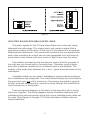
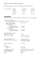
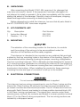
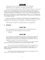
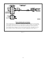
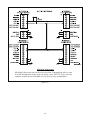
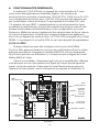
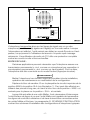
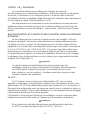
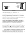
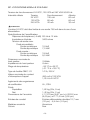
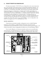
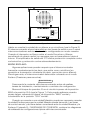
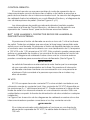
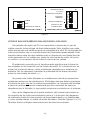
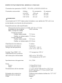
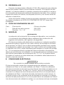
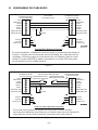
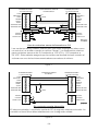
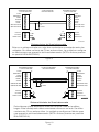
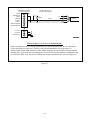
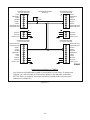
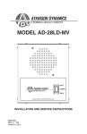
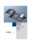
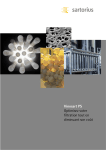
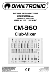
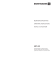
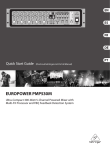
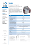
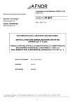
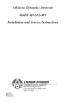
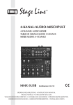
Model 310LD-MV
Installation and
Maintenance Manual
2561328A
REV. A 613
Printed in U.S.A.
français...............page 15
español...............página 29
Industrial Systems
2645 Federal Signal Drive
University Park, IL 60484-3167
Phone: 1-877-289-3246 ï 1-708-534-4756 ï Fax: 1-708-534-4887
www.federalsignal-indust.com ï www.fs-isys.com
© 2013 Federal Signal Corp.
INSTALLATION AND SERVICE INSTRUCTIONS
FOR
MODEL 310LD-MV
SAFETY MESSAGE TO INSTALLERS, USERS AND
MAINTENANCE PERSONNEL
It is important to follow all instructions shipped with this product. This
device is to be installed by a trained electrician who is thoroughly familiar
with the National Electrical Code and will follow NEC Guidelines as well as
local codes.
The selection of the mounting location for the device, its controls
and the routing of the wiring is to be accomplished under the direction
of the facilities engineer and the safety engineer. In addition, listed below
are some other important safety instructions and precautions you should
follow:
•
ThisisnotaListedsafetydeviceandisnotintendedtobe
used as such.
•
Readandunderstandallinstructionsbeforeinstallingor
operating this equipment.
•
Disconnectpowerbeforeconnectingordoingany
maintenance on this intercom.
•
Alleffectivewarningspeakersproduceloudsoundswhich
may cause in certain situations, permanent hearing loss. You
shouldtakeappropriateprecautionssuchaswearinghearing
protection.
•
Aftertestingiscomplete,provideacopyofthisinstruction
sheet to all operating personnel.
•
Establishaproceduretoroutinelychecktheintercom
installation for integrity and proper operation. Any maintenance
must be performed by a trained electrician in accordance with
NEC guidelines and local codes.
Failure to follow all safety precautions and instructions may result in
property damage, serious injury, or death to you or others.
-1-
A. GENERAL FEATURES.
The310LD-MVintercomisa2-waycommunicationsdevicedesigned
for light duty industrial applications. Nominal operating voltages include
120/240VAC,50/60Hzand24VDC.Voltagechangesforthe120/240VAC
are internally switch selectable and the AC line is fused with a 1/2 ampere
250volttypeGMCfuse.Theunitalsooffersinternallyselectablebalanced
or unbalanced line operation, transformer isolated audio inputs and internally
selectableMasterorSlavemodeconfigurations.Acallbuttonwithremote
calldrycontactsisalsofactorysuppliedintheunit.The310LD-MVhasa
NEMA1enclosureandisaULListedandCSACertifiedsignalappliance.
MASTER MODE:
EachintercomcanbeconFiguredasaMasterunit(Push-to-Talk)or
aSlaveunit(Push-to-Listen)bychangingtheMAS/SLAjumper(J3)onthe
printedcircuitboard(seeFigure1).Theintercomcomesfromthefactory
setintheMaster(MAS)mode.
IntheMastermodetheintercomactsasanamplifier,constantly
broadcastingoveritsspeakeranysignalthatitreceivesonthesignallines.
HoldingdowntheListen/Talkswitchchangestheunitfromaspeakertoa
microphone(seeFigure2).Theintercomwillnowtransmit over the signal
linestoadditionalintercom(s)alsosetinthemastermode.Whentheswitch
Figure 1.
-2-
Figure 2.
isreleaseditwilldefaultbacktotheListenorSpeakermode,allowingthe
usertoreceiveanymessagestransmittedbacktoit.Theoutputamplifierof
the 310 offers full short circuit protection and over heat protection.
SLAVE MODE:
Some applications may require that the intercom constantly transmit
(i.e.actasamicrophone)asopposedtoconstantlyreceive(i.e.,actasa
speaker).ToaccomplishthistheintercommustbeswitchedintotheSlave
(Push-to-Listen)mode.
Disconnectpowertotheintercombeforeanyinstallation,
maintenance,orconfigurationchangesareperformed.
MovetheJ3jumperblockontheP.C.boardfromtheMAStoSLA
position(seeFigure1).Thiscanbedoneusinglongnosepliers,pullingthe
blockoffthe“MAS”andcenterpositionandplacingitonthe“SLA”and
center position.
WhenhookedtoaMasterunititmaybenecessarytooverridethe
SlaveunitinorderfortheMasterunittobeabletotransmit.Theremote
controlandgroundlinesmustbeconnectedbetweentheMasterandthe
Slaveunit.ParagraphG.WIRINGDIAGRAMScontainswiringdiagramsof
typicalintercomconfigurations.
-3-
REMOTE CONTROL:
Remote control is used to change the operation mode of a remote
intercomfromlistentotalkorfromtalktolistenuponactivationofalocal
intercom.ThewiringdiagramsectionillustratesMaster/SlaveInstallation
andUsingFootSwitchesDiagrams.(SeeFigures5and6.)
Normally open foot switches can also be connected to the Remote
Controllineandgroundinordertoallow“handsfree”operationofthe
listen/talkfunctions.
CALL BUTTON AND CALL DRY CONTACTS TO EXTERNAL DEVICE:
Depressingthecallbuttonsendsa1kHztoneontothesignallines.All
unitslisteningtothelinewillthenbroadcastthissignalasacall.Depressing
the call button also closes a normally open dry contact rated at 0.4 amps
at125VACor1.25ampsat24VDC.Thiscontactcanbeusedtotrigger
a remote sounder or light in order to accent the call feature. The wiring
diagram illustrates how an external light or horn can be wired in to augment
thecalltone.(SeeFigure7.)
The call signal is substantially louder than normal voice messages
beingcarriedontheline.Donotdepressthecallswitchwhile
carrying on a conversation with someone on the system. This will
subject the listener to very loud sound levels.
24VDC:
The310iscapableofsendingDCpowertoanotherunitwhichis
mountedinaremotelocationwithoutlocalpower.24VDCisavailablefrom
positions6and7ofterminalblockJ7.Itcanberunalongwiththesignal
lines to an intercom in a remote location. Only one unit should share the
power supply of another unit in any installation.
Figure 8 in the wiring diagrams section shows how two intercoms can be
hookedupifnoremotepowerisavailable.
Ifanintercomisintendedtoberunoffofaseparate24VDC
supply,theoutputmustbelimitedto24VDC,760mAoutput.
-4-
Figure 3.
ISOLATED BALANCED/UNBALANCED LINES:
The audio signals for the 310 are transmitted over a wire pair using
balanced line technology. This means each wire carries a signal that is
opposite in polarity of the other. At the input of the intercom is an isolated
balanced line transformer. This transformer subtracts the two signals from
each other providing an output free of noise generated onto the wires by
someothernoisesourcesuchasamotororlightfixturenearthewires.
The isolation provided by the transformer means that the grounds of
the units are not connected by the audio lines. Therefore, ground loops
andotherproblemscausedbynon-isolatedsystemsareavoided.The
polarityoftheaudiolinesbetweenthe+and-signalterminalsneednotbe
maintained.
A shielded cable can be used in installations where extreme problems
from interference are suspected. The shield should always be connected to
the ground of only one of the intercoms. Connecting the shield to ground
at both ends will cause ground currents to travel through the shield which
could cause hum in the system.
Thereareseveraldiagramsinthebackofthemanualtoaidinwiring
intercoms together. The wiring diagram section illustrates balanced and
unbalanced line interconnection along with how a shielded audio cable can
beused.(SeeFigures5through12.)Italsoillustratesmultipleintercom
interconnections.
-5-
MODEL 310LD-MV SPECIFICATIONS
OperatingVoltage 24VDC,120VACand240VAC50/60Hz
CurrentDraw
Voltage
Operating
Standby
24VDC
120 mA
60 mA
120VAC
80 mA
60 mA
240VAC
40 mA
30 mA
The24VDCinputmustbelimitedto760mAoutifrunfromasupply.
AmplifierSpecifications
FrequencyResponse(–6dB)150Hzto12kHz
Input Impedance
3400 ohms
Max.OutputVoltage
SineWave:
BalancedOutput
15Vrms
UnbalancedOutput
7.5Vrms
SquareWave:
BalancedOutput
19Vrms
UnbalancedOutput
9.5Vrms
SpeakerRating 2watts
SpeakerImpedance
TemperatureRange
8ohm
–31°Fto+150°F
(–35°Cto+66°C)
FuseTypeGMC-1/2
Call Switch Contact Rating
1/2amp,250V
400 mA at 125VAC
1.25ampat24VDC
AgencyApprovals
UL,CSA
Weight
Shipping
Net
HousingDimensions
ConduitEntrances
HousingMaterial
Color
3lb,9oz
3 lb, 2 oz
6.87"Wx8.00"Hx3.05"D
Dual1/2"-3/4"Knockouts
Aluminum
Black
-6-
B. UNPACKING.
AfterunpackingtheModel310LD-MV,examineitfordamagethat
may have occurred in transit. If the equipment has been damaged, do
notattempttoinstalloroperateit,fileaclaimimmediatelywiththecarrier
statingtheextentofthedamage.Carefullycheckallenvelopes,shipping
labels and tags before removing or destroying them.
Beforeattemptingtoinstalltheintercom,besurethatallpartslistedin
theKITCONTENTSLISThavebeensupplied.
C. KIT CONTENTS LIST.
Qty.
Description
Part Number
1 InstructionManual
1 Resistor,1K,1W
2561328
K101216
D. MOUNTING.
The selection of the mounting location for the device, its controls
and the routing of the wiring is to be accomplished under the
direction of the facilities and the safety engineer.
Theintercomisintendedtobemountedonanyrelativelyflatandrigid
surface by the four mounting holes in the interior of the housing. Figure 4 is
adimensionaloutlinedrawingshowingthepropermountingconfiguration.
The four mounting holes are .202 in diameter and are designed to accept a
#10 mounting screw. Hardware for mounting the intercom to the surface is
leftuptotheinstaller.Theintercomhousinghastwocombination1/2"-3/4”
knockoutsinthebottom.Wheninstallingtheconduittotheseopenings,
choosing the size and type of connector is left up to the installer.
E. ELECTRICAL CONNECTIONS.
Donotconnectwireswhenpowerisapplied.
The intercom has two wiring compartments, one for Class I wiring and the
second for Class II wiring. All wiring to the intercom is terminated at two
pcboardmountedterminalblocksprovided.TheACPhaseandCommon,
alongwithEarthGround,arelandedinathree-positionterminalblock(J2)
in the Class I wiring compartment. The signal lines, remote control lines,
remotepower,andcalldrycontactsarelandedinaseven-positionterminal
block(J7)intheClassIIwiringcompartment.Thetwowiringsectionsare
isolatedbyafishpaperbarrier.
-7-
Disconnectpowertotheintercombeforeanyinstallation,
maintenance,orconfigurationchangesareperformed.
TherearethreejumpersshownonthePCboardinFigure7whichmay
need to be moved depending on the desired operation of the intercom.
J4andJ5areforoperatingtheintercomineitherabalancedsignallineor
unbalancedsignallineconfiguration.Thesemustbemovedtogetherasa
pair.Theyarefactorysetinthebalancedlineposition.J3isforconfiguring
the intercom as either a master or slave device. The intercom is factory set
in the master position.
There is a switch on the board, in the Class I wiring compartment, to
con Figure the operation of the board from 120VAC to 240VAC. The switch
isfactorysetfortheintercomtooperateon120VAC(seeFigure3).
SeeFigures5through12fortypicalintercomconfigurations.
F.
SERVICE.
Any maintenance must be performed by a trained electrician in
accordance with NEC guidelines and local codes.
1. General.
The call signal is substantially louder than normal voice messages
beingcarriedontheline.Donotdepressthecallswitchwhile
carrying on a conversation with someone on the system. This will
subject the listener to very loud sound levels.
Federal Signal will service your equipment or provide technical
assistance with any problems that cannot be handled locally.
Any units returned to Federal Signal for service, inspection, or
repairmustbeaccompaniedbyaReturnMaterialAuthorization.This
R.M.AcanbeobtainedfromthelocalDistributororManufacturer’s
Representative.
At this time a brief explanation of the service requested or the
nature of the malfunction, should be given.
-8-
Figure 4.
Address all communications and shipments to:
Federal Signal Corp.
Industrial Systems
2645FederalSignalDr.
UniversityPark,IL60484-3167
2. Replacement Parts.
ReplacefusewithGMC-1/2only.DONOTsubstitute.
Description
PartNumber
Resistor,1K,1W
PCBA
Switch
K101216
K2001290
K122283
-9-
G. WIRING DIAGRAMS.
Master Slave Installation
Inthisinstallation,theMasterisconstantlybroadcastingaudiofromthe
Slave.Pushingthelisten/talkswitchoneitherunitforcestheSlaveintothe
listenmodeandtheMasterintothetalkmode.TheMAS/SLAjumpermust
beplacedintheSLAmodeforthisoperationontheslaveunit.
Figure 5.
Using Foot Switches
Usingnormallyopen,simplecontactclosurefootswitches(customer
supplied)allowsfortotalhandsfreeoperationofthelisten/talkfunctions.
Figure 6.
-10-
Using Call Dry Contacts with AC
The dry contacts can be used to switch devices such as an auxiliary
sound or light when call is depressed. The maximum ratings for the dry
contactsare0.4ampsat125VACand1.25ampsat24VDC.Thismethod
assures a call is received even when the volume on one of the intercoms
is turned all the way down.
Figure 7.
No Remote Power Available
IntercomIsuppliestheDCpowertothesecondintercom.Earthground
must be wired on the second unit.
Figure 8.
-11-
INTERCOM I
BASIC BALANCED
LINE SYSTEM
310LD-MV MASTER
INTERCOM II
310LD-MV SLAVE
J7
J7
24 VDC
7
7
24 VDC
GROUND
6
6
GROUND
REMOTE
5
5
REMOTE
AUDIO +
4
4
AUDIO +
3
3
AUDIO -
DRY CONTACT
2
DRY CONTACT
1
NEUTRAL
3
2
1K
1 WATT
J2
HOT
EARTH GND.
2
J2
AC
AC
Basic Balanced Line System
DRY CONTACT
1
DRY CONTACT
3
NEUTRAL
2
1
1
AUDIO -
HOT
EARTH GND.
290A3084
This is a simple system with only two conductors connected between the
units. AC power is utilized at both sites. The Unit is factory con Figured for
balancedlineoperation.(NOTE:bothjumpersinBALposition.)
Figure 9.
Shielded Balanced Line System
This system offers maximum isolation from noise over long runs. The
shield should only be grounded at one side. AC power is utilized at both
sites. The unit is factory con Figured for balanced line operation.
(NOTE:bothjumpersinBALposition.)
Figure 10.
-12-
Basic Unbalanced Line System
Thisconfigurationisusedwhenhookingtootherproductsonthemarket.
This system does not offer the same level of noise isolation as a balanced
linesystemandshouldonlybeusedwhenhookingtoexistingdevices.
The neighboring jumpers on the circuit board must be changed from the
BALpositiontotheUNBpositionfortheseinstallations(seeFigure1).
Figure 11.
-13-
Multiple Intercoms
Multipleintercomscanbetiedtooneline.Depressingtalkonany
unitwillbroadcastaudiooverallotherunits.(NOTE:onlyoneline
resistorneedstobeinstalledonthelineforanyinstallation.)
Figure 12.
-14-
CONSIGNES D’INSTALLATION ET
D’ENTRETIEN
DU MODÈLE 310LD-MV
MESSAGE DE SÉCURITÉ DESTINÉ AUX INSTALLATEURS, AUX
UTILISATEURS ET AU PERSONNEL D’ENTRETIEN
Il est important de respecter toutes les consignes jointes à ce produit
aumomentdel’expédition.Cetappareildoitêtreinstalléparunélectricien
qualifiéquimaîtriseparfaitementleCodenationald’électricitéetqui
respectera les directives CNE ainsi que les codes locaux.
Lechoixdulieudemontagedudispositif,desescommandesetde
l’acheminementdescâblesdoitêtreeffectuésousladirectiondel’ingénieur
responsabledesinstallationsetdel’ingénieurresponsabledelasécurité.
Voiciparailleursunelistecomplémentaired’instructionsetdeprécautionsde
sécuritéimportantesàrespecter:
•
Ilnes’agitpasd’undispositifdesécuritéhomologuéetce
dispositifn’apasvocationàêtreutilisécommetel.
•
Lireetcomprendretouteslesinstructionsavantd’installerou
d’utilisercematériel.
•
Déconnecterl’alimentationavantdebrancheroud’effectuer
touteopérationdemaintenancesurcetinterphone.
•
Tousleshaut-parleursd’avertissementefficacesproduisentdes
sonspuissants,quipeuvententraîner,danscertainessituations,
unepertepermanentedel’ouïe.Ilestrecommandédeprendre
lesprécautionsappropriées,commel’utilisationd’uneprotection
acoustique.
•
Unefoislesteststerminés,fournirunecopiedecettefichede
consignes à tout le personnel de service.
•
Établiruneprocéduredevérificationrégulièredel’intégritéetdu
bonfonctionnementdel’installationd’interphone.Toutentretien
decetappareildoitêtreexécutéparunélectricienformé
conformémentauxdirectivesduCNEainsiqu’auxcodeslocaux.
Lenon-respectdel’ensembledesmesuresetconsignesdesécuritépeut
entraînerdesdommagesmatériels,oudesblessuresgravesvoiremortelles
despersonnesconcernéesoud’autrespersonnes.
-15-
A. FONCTIONNALITÉS GÉNÉRALES.
L’interphone310LD-MVestunappareildecommunicationà2voies
conçupourdesapplicationsindustrielleslégères.Lestensionsde
fonctionnement nominales comprennent 120/240 VCA, 50/60 Hz et 24 VCC.
Leschangementsdetensionpour120/240VCApeuventêtresélectionnés
parcommutateurinterneetlaligneCAestéquipéed’unfusible250volts
1/2ampère,detypeGMC.L’appareilpermetunfonctionnementenligne
symétriqueouasymétrique,quipeutêtresélectionnédefaçoninterne,des
entréesaudioisoléespartransformateuretdesconfigurationsenmode
EsclaveouMaîtrequipeuventégalementêtresélectionnéesdefaçoninterne.
Unboutond’appelaveccontactssecsd’appelàdistanceestégalement
fournisurcetappareilensortied’usine.Le310LD-MVestéquipéd’uncoffret
NEMA1,homologuéULetcertifiéCSAentantquedispositifdesignalisation.
MODE MAŒ
TRE :
ChaqueinterphonepeutêtreconfigurécommeuneunitéMaître
(Push-to-Talk,appuyez-parlez)oucommeuneunitéEsclave(Push-to-Listen,
appuyez-écoutez)enchangeantlecavalierMAS/SLA(J3)surlaplaquette
decircuitsimprimés(voirIllustration1).L’interphoneestconfiguréenmode
Maître(MAS)àl’usine.
DanslemodeMaître,l’interphoneagitcommeunamplificateur,diffusant
constammentsursonhaut-parleurtoutsignalqu’ilreçoitsurleslignesde
signal.Lefaitdemaintenirl’interrupteurÉcoute/Paroleenfoncépermute
l’appareilduhaut-parleurverslemicrophone(sereporteràl’Illustration2).
VERS
HAUT-PARLEUR
VERS
COMMUTATEUR
CAVALIER
MAÎTRE /
ESCLAVE
CAVALIER
SYM/ASYM (2)
COMMUTATEUR
120 VCA/240 VCA
CONTRÔLE
DU VOLUME
FUSIBLE
CÂBLAGE CLASSE II
CÂBLAGE
CLASSE I
Illustration 1.
-16-
APPELLER
ÉCOUTER
PARLER
AVERTISSEMENT : METTRE HORS TENSION AVANT DE RETIRER LE COUVERCLE
Illustration 2.
L’interphonetransmettra alors sur les lignes de signal vers un ou des
interphone(s)additionnel(s)égalementréglé(s)surlemodemaître.Lorsque
l’interrupteurestrelâché,l’unitérevientpardéfautenmodeÉcouteouHautparleur,cequipermetàl’utilisateurderecevoirn’importequelmessage
retransmis.L’amplificateurdesortiedu310offreuneprotectioncomplète
contrelescourts-circuitsetlessurchauffes.
MODE ESCLAVE :
Certainesapplicationspeuventnécessiterquel’interphoneassureune
transmissionpermanente(c.-à-d.commeunmicrophone)paroppositionà
uneréceptionpermanente(c.-à-d.commeunhaut-parleur).Pourcefaire,
l’interphonedoitêtrecommutésurlemodeEsclave(Appuyez-écoutez).
AVERTISSEMENT
Mettrel’interphonehorstensionavantdeprocéderàtouteinstallation,
opérationdemaintenanceoumodificationdelaconfiguration.
DéplacerleblocdecavalierJ3surlaplaquettedecircuitsimprimésdela
positionMASàlapositionSLA(voirIllustration1).Cecipeutêtreeffectuéen
utilisantdespincesàlongnez,entirantleblochorsdelaposition«MAS»et
centralepourleplacersurlaposition«SLA»etcentrale.
Lorsqu’elleestreliéeàuneunitéMaître,ilestnécessaired’interrompre
l’unitéEsclavedefaçonàcequel’unitéMaîtresoitcapabledetransmettre.
Leslignesdecontrôleàdistanceetdeterredoiventêtreconnectéesentre
lesunitésMaîtreetEsclave.LeparagrapheG.SCHÉMASD’INSTALLATION
contientlesschémasd’installationdesconfigurationsd’interphonetypiques.
-17-
CONTR‘ LE ¿ DISTANCE :
Lecontrôleàdistanceestutilisépourchangerlemodede
fonctionnementd’uninterphoneàdistance,d’écouteàparoleoudeparole
àécoute,àl’activationd’uninterphonelocal.Lasectiondesschémas
d’installationillustrel’installationMaître/Esclaveetl’utilisationdesinterrupteurs
àcommandeaupied.(VoirIllustrations5et6).
Lesinterrupteursàcommandeaupiednormalementouvertspeuvent
égalementêtreconnectésàlalignedecontrôleàdistanceetàlaterrede
façonàpermettreunfonctionnement«mainslibres»desfonctionsÉcoute/
parole.
BOUTON DíAPPEL ET CONTACTS SECS DíAPPEL VERS UN APPAREIL
EXTERNE :
Lefaitd’appuyersurleboutond’appelenvoieunetonalité1kHzsur
leslignesdesignal.Touteslesunitésécoutantsurlalignediffuserontalors
cesignalcommeunappel.Lefaitd’appuyersurleboutond’appelferme
égalementuncontactsecnormalementouvertayantunevaleurnominalede
0,4Aà125VCAoude1,25Aà24VCC.Cecontactpeutêtreutilisépour
déclencherunrésonateurouunelumièreàdistancedefaçonàaccentuer
lacaractéristiqued’appel.Leschémad’installationillustrecommentintégrer
lecâblaged’unelumièreexterneoud’unklaxonpouraugmenterlatonalité
d’appel.(VoirIllustration7).
ATTENTION
Lesignald’appelestsignificativementpluspuissantqueles
messagesvocauxnormauxtransportéssurlaligne.Nepasappuyer
surl’interrupteurd’appellorsqu’uneconversationestencours
avecquelqu’unsurlesystème.L’auditeurseraitalorssoumisàdes
niveauxsonorestrèspuissants.
24 VCC :
Le310estenmesured’envoyerl’alimentationCCversunautre
appareilmontédansunemplacementdistantsansalimentationlocale.Une
alimentation24VCCestdisponibleàpartirdespositions6et7dubornierJ7.
Ellepeutêtreacheminéeavecleslignesdesignalversuninterphonedansun
emplacementdistant.Danstouteinstallation,unseulappareildevraitpartager
l’alimentationélectriqued’unautreappareil.
L’Illustration8delasectionSchémasd’installationmontrecommentdeux
interphonespeuventêtrereliésenl’absenced’alimentationàdistance.
ATTENTION
Siuninterphonedoitêtrealimentéparunealimentationdistincte
24VCC,lasortiedoitêtrelimitéeà24VCC,760mA.
-18-
ENTRÉE /
SORTIE 24 VCC
TERRE
CONTRÔLE À
DISTANCE
HAUT-PARLEUR
DISTANT
COMMUN
PHASE
CONTACT
DʼAPPEL EXT.
TERRE
CÂBLAGE CLASSE II
CÂBLAGE CLASSE I
Illustration 3.
LIGNES SYM…TRIQUES/ASYM…TRIQUES ISOL…ES :
Lessignauxaudiodu310sonttransmissurunepairedefilsutilisantla
technologiedelignesymétrique.Celasignifiequechaquefiltransporteun
signaldontlapolaritéestopposéeàcelledel’autrefil.Untransformateur
delignesymétriqueisoléeestprésentàl’entréedel’interphone.Ce
transformateureffectuelasoustractiondesdeuxsignauxafind’obtenirune
sortiesansbruitgénéréesurlesfilsparuneautresourcedebruittellequ’un
moteurouunappareild’éclairageàproximitédesfils.
L’isolationfournieparletransformateursignifiequelesconnexions
demiseàlaterredesappareilsnedépendentpasdeslignesaudio.Par
conséquent,onévitelesbouclesdemiseàlaterreetautresproblèmes
causéspardessystèmesquinesontpasisolés.Lapolaritédeslignesaudio
entrelesbornesdesignal+et-n’apasbesoind’êtremaintenue.
Uncâbleblindépeutêtreutilisédanslesinstallationssoupçonnées
deprésenterdegrosproblèmesd’interférences.Leblindagedoittoujours
êtreconnectéàlaterred’unseulinterphoneuniquement.Leraccordement
dublindageàlaterreauniveaudesdeuxextrémitéspeutfairepasserdes
courantsdeterredansleblindage,cequipeutgénérerunbourdonnement
danslesystème.
Plusieursdiagrammessontdisponiblesenfindemanuelpourvousaider
àcâblerlesinterphonesensemble.LasectionSchémasd’installationillustre
lesinterconnexionsdeslignessymétriquesetasymétriquesainsiquela
manièredontlecâbleaudioblindépeutêtreutilisé.(VoirIllustrations5à12).
Demultiplesinterconnexionsd’interphonesontégalementprésentées.
-19-
SP…CIFICATIONS MOD»LE 310LD-MV.
Tension de fonctionnement 24 VCC, 120 VCA et 240 VCA 50/60 Hz
Intensitéutilisée
Tension
24 VCC
120 VCA
240 VCA
Fonctionnement
120 mA
80 mA
40 mA
Attente
60 mA
60 mA
30 mA
ATTENTION
L’entrée24VCCdoitêtrelimitéeàunesortie760mAdanslecasd’une
alimentation.
Spécificationsdel’amplificateur
Réponsedefréquence(–6dB)150Hzà12kHz
Impédanced’entrée
3400ohms
Tension de sortie max.
Ondesinusoïdale:
Sortiesymétrique
15Veff
Sortieasymétrique
7,5Veff
Ondecarrée:
Sortiesymétrique
19Veff
Sortieasymétrique
9,5Veff
Puissance nominale du
haut-parleur
Impédanceduhaut-parleur
Plagedetempérature
TypedefusibleGMC-1/2
Valeur nominale du contact
d’interrupteurd’appel
2Watts
8ohm
–35°Cà+66°C
(–31°Fà+150°F)
1/2A,250V
400mAà125VCA
1,25 A à 24 VCC
Agrémentsdesorganismes
decertification UL,CSA
Poids
Expédition
Net
Dimensionsdel’enceinte
Entréesdeconduit
Matériauenceinte
Coloris
1,62kg(3lb,9oz)
1,42kg(3lb,2oz)
L174,5mm(6,87po.)xH203,2mm
(8,00po.)xP77,5mm(3,05po.)
Entréesdéfonçablesdoubles12,7mm
(1/2po.)-6,4mm(1/4po.)
Aluminium
Noir
-20-
B. DÉBALLAGE.
Aprèsavoirdéballélemodèle310LD-MV,vérifiersoigneusements’ila
étéendommagélorsdutransport.Sil’équipementaétéendommagé,ne
pastenterdel’installeroudelefairefonctionner.Déposerimmédiatement
uneréclamationauprèsdutransporteur,déclarantl’étenduedesdommages.
Examinersoigneusementtouteslesenveloppes,étiquettesd’expéditionet
autresétiquettesavantdelesretireroudelesdétruire.
Avantdetenterd’installerl’interphone,s’assurerquetouteslespièces
listéesdanslaLISTEDUCONTENUDUKITontétéfournies.
C. LISTE DU CONTENU DU KIT.
Qté.
1
1
Description
Manueld’instructions
Résistance,1K,1W
N° de pièce
2561328
K101216
D. MONTAGE.
ATTENTION
Lechoixdulieudemontagedudispositif,desescommandesetde
l’acheminementdescâblesdoitêtreeffectuésousladirectionde
l’ingénieurresponsabledesinstallationsetdelasécurité.
L’interphoneestdestinéàêtremontésurunesurfacerelativement
plateetrigidevialesquatretrousdemontageàl’intérieurdel’enceinte.
L’Illustration4estunschémacotéindiquantuneconfigurationdemontage
correcte.Lesquatretrousdemontageontundiamètrede5,13mm
(0,202po.)etsontconçuspouraccepterunevisdemontagen°10.Le
choixdumatérielpourlemontagedel’interphonesurlasurfaceestlaissé
àlaconvenancedel’installateur.L’enceintedel’interphonepossèdedeux
possibilitésd’entréesdéfonçables12,7mm(1/2po.)-6,4mm(1/4po.)dans
lapartieinférieure.Lorsdel’installationduconduitsurcesouvertures,lechoix
delatailleetdutypedeconnecteurestlaisséàladiscrétiondel’installateur.
E. BRANCHEMENTS ÉLECTRIQUES.
AVERTISSEMENT
Nepasconnecterdecâbleslorsquelesystèmeestsoustension.
L’interphonepossèdedeuxcompartimentsdecâblage,l’unpourlescâbles
deClasseIetl’autrepourlescâblesdeClasseII.Laterminaisondetoutle
câblageàl’interphonedoitêtreeffectuéesurlesdeuxborniersàplaquettes
decircuitsimprimésfournis.LesfilsdephaseCAetcommunainsiquela
miseàlaterreserejoignentdansunbornieràtroispositions(J2)dansle
compartimentdecâblagedeClasseI.Leslignesdesignal,leslignesde
contrôleàdistance,l’alimentationàdistanceetlescontactssecsd’appel
serejoignentdansunbornieràseptpositions(J7)danslecompartiment
decâblagedeClasseII.Lesdeuxsectionsdecâblagesontisoléesparune
barrièreenfibrevulcanisée.
-21-
AVERTISSEMENT
Mettrel’interphonehorstensionavantdeprocéderàtoute
installation,opérationdemaintenanceoumodificationdela
configuration.
Troiscavaliers(cf.plaquettedecircuitsimprimésenIllustration7)
peuventavoirbesoind’êtredéplacésselonlefonctionnementsouhaité
pourl’interphone.J4etJ5sontdestinésàactiverl’interphonedansune
configurationdelignedesignalsymétriqueouasymétrique.Ilsdoiventêtre
déplacésensembleentantquepaire.Ilssontconfigurésàl’usineenposition
delignesymétrique.J3sertàconfigurerl’interphoneentantquedispositif
maîtreouesclave.L’interphoneestréglésurlapositionMaîtreàl’usine.
Surlepanneau,danslecompartimentdecâblagedeClasseI,
uncommutateurpermetdeconfigurerlefonctionnementdupanneau
de120VCAà240VCA.Lecommutateurestrégléàl’usinepourque
l’interphonefonctionnesur120VCA(voirIllustration3).
ConsulterlesIllustrations5à12pourlesconfigurationstypiques
d’interphone.
F.
ENTRETIEN.
ATTENTION
Toutentretiendecetappareildoitêtreexécutéparunélectricien
forméconformémentauxdirectivesduCNEainsiqu’auxcodes
locaux.
1. Généralités.
ATTENTION
Lesignald’appelestsignificativementpluspuissantqueles
messagesvocauxnormauxtransportéssurlaligne.Nepasappuyer
surl’interrupteurd’appellorsqu’uneconversationestencours
avecquelqu’unsurlesystème.L’auditeurseraitalorssoumisàdes
niveauxsonorestrèspuissants.
FederalSignalprocéderaàl’entretiendevotreéquipementouvous
fournirauneassistancetechniquepourtoutproblèmequinepeutêtrerésolu
sur place.
TouslesappareilsretournésàFederalSignalpourentretien,
inspectionouréparationdoiventêtreaccompagnésd’uneautorisation
deretourduproduit.Vouspouvezobtenircetteautorisationauprèsdu
distributeurlocaloud’unreprésentantdufabricant.
-22-
Vousdevezaussifournirunebrèveexplicationduservicerequisou
delanaturedudysfonctionnementlorsdelarestitutiondel’appareil.
APPELLER
ÉCOUTER
PARLER
AVERTISSEMENT : METTRE HORS TENSION AVANT DE RETIRER LE COUVERCLE
ENTRÉE CÂBLE
CLASSE
ARRIÈRE
AVANT
COMBINAISONS DʼENTRÉES DÉFONÇABLES
12,7 MM (1/2 PO.) - 6,4 MM (1/4 PO.)
Illustration
4. CÂBLE CLASSE II
ENTRÉE
BAS
Adressepourlescommunicationsetlesexpéditions:
Federal Signal Corp.
Industrial Systems
2645FederalSignalDr.
UniversityPark,IL.60484-3167
2. Pièces de rechange.
AVERTISSEMENT
RemplacerlefusibleparunfusibledemarqueGMC-1/2uniquement.
NE PAS utiliser de substitut.
Description
N°depièce
Résistance,1K,1W
Plaquettedecircuitsimprimés
Commutateur
K101216
K2001290
K122283
-23-
G. SCHÉMAS D’INSTALLATION.
INSTALLATION
MAÎTRE / ESCLAVE
INTERPHONE I
310LD-MV MAÎTRE
INTERPHONE II
310LD-MV MAÎTRE
24 VCC
24 VCC
TERRE
TERRE
CONTRÔLE À
DISTANCE
CONTRÔLE À
DISTANCE
AUDIO +
AUDIO +
AUDIO -
AUDIO CONTACT SEC
1K
CONTACT SEC
CONTACT SEC
1 WATT
CONTACT SEC
NEUTRE
NEUTRE
CA
CA
SOUS TENSION
SOUS TENSION
MISE À LA TERRE
MISE À LA TERRE
Installation MaÓtre / Escla
ve
Danscetteinstallation,l’unitéMaîtrediffusedefaçonconstantedessons
(audio)àpartirdel’unitéEsclave.Lefaitd’appuyersurl’interrupteurécoute/
paroledel’unedesdeuxunitésforcel’Esclavedanslemode«écoute»et
leMaîtredanslemode«parole».LecavalierMAS/SLAdoitêtreplacéen
modeSLApourcetteopérationsurl’unitéEsclave.
Illustration 5.
INTERPHONE I
310LD-MV MAÎTRE
24 VCC
UTILISATION D’INTERRUPTEURS À
COMMANDE AU PIED
INTERRUPTEURS À
INTERRUPTEURS À
COMMANDE AU PIED N.O. COMMANDE AU PIED N.O.
INTERPHONE II
310LD-MV MAÎTRE
24 VCC
TERRE
TERRE
CONTRÔLE À
DISTANCE
CONTRÔLE À
DISTANCE
AUDIO +
AUDIO +
AUDIO -
AUDIO CONTACT SEC
1K
CONTACT SEC
CONTACT SEC
1 WATT
CONTACT SEC
NEUTRE
SOUS TENSION
CA
CA
MISE À LA TERRE
NEUTRE
SOUS TENSION
MISE À LA TERRE
Utilisation díinterrupteurs ‡ commande au pied
L’utilisationd’interrupteursàcommandeaupieddefermeturepar
simplecontactnormalementouvert(fournisparleclient)permetun
fonctionnement«mainslibres»detouteslesfonctionsd’écoute/parole.
Illustration 6.
-24-
UTILISATION DE CONTACTS SECS
D’APPEL AVEC CA
INTERPHONE I
310LD-MV MAÎTRE
24 VCC
INTERPHONE II
310LD-MV MAÎTRE
24 VCC
1K
TERRE
TERRE
1 WATT
CONTRÔLE À
DISTANCE
CONTRÔLE À
DISTANCE
AUDIO +
AUDIO +
AUDIO -
AUDIO -
CONTACT SEC
CONTACT SEC
CONTACT SEC
CONTACT SEC
PUISSANCE
PUISSANCE
NEUTRE
NEUTRE
CA
CA
SOUS TENSION
SOUS TENSION
MISE À LA TERRE
MISE À LA TERRE
Utilisation de contacts secs díappel avec CA
Lescontactssecspeuventêtreutiliséspourpermuterlesdispositifstelsqu’un
sonouunelumièreauxiliairelorsqueleboutond’appelestenfoncé.Lesvaleurs
nominales maximales pour les contacts secs sont de 0,4 A à 125 VCA et 1,25 A
à24VCC.Cetteméthodegarantitlaréceptiond’unappelmêmelorsquele
volumesurl’undesinterphonesestcomplètementdésactivé.
Illustration 7.
AUCUNE ALIMENTATION À
DISTANCE DISPONIBLE
INTERPHONE I
310LD-MV MAÎTRE
INTERPHONE II
310LD-MV MAÎTRE
24 VCC
24 VCC
TERRE
TERRE
CONTRÔLE À
DISTANCE
CONTRÔLE À
DISTANCE
AUDIO +
AUDIO +
AUDIO -
AUDIO CONTACT SEC
1K
CONTACT SEC
CONTACT SEC
1 WATT
CONTACT SEC
NEUTRE
SOUS TENSION
NEUTRE
CA
SOUS TENSION
MISE À LA TERRE
MISE À LA TERRE
Aucune alimentation ‡ distance disponible
L’interphoneIfournitl’alimentationCCaudeuxièmeinterphone.Lamiseàla
terredoitêtreraccordéesurledeuxièmeappareil.
Illustration 8.
-25-
SYSTÈME DE LIGNE
SYMÉTRIQUE DE BASE
INTERPHONE I
310LD-MV MAÎTRE
J7
24 VCC
7
TERRE
6
CONTRÔLE À
DISTANCE
AUDIO +
AUDIO -
INTERPHONE II
310LD-MV MAÎTRE
J7
24 VCC
7
TERRE
6
5
5
4
4
3
3
CONTRÔLE À
DISTANCE
AUDIO +
AUDIO -
CONTACT SEC
2
1K
2
CONTACT SEC
1
1 WATT
1
CONTACT SEC
3
NEUTRE
2
SOUS TENSION
J2
NEUTRE
SOUS TENSION
MISE À LA TERRE.
3
J2
CA
2
CA
1
1
CONTACT SEC
MISE À LA TERRE
290A3084
SystËme de ligne symÈtrique de base
Ils’agitd’unsystèmesimpleavecseulementdeuxconducteursconnectés
entrelesappareils.L’alimentationCAestutiliséesurlesdeuxsites.
L’appareilestconfiguréàl’usinepouruneexploitationenlignesymétrique.
(REMARQUE:lesdeuxcavalierssontenpositionSYM.)
Illustration 9.
SYSTÈME DE LIGNE
SYMÉTRIQUE BLINDÉE
INTERPHONE I
310LD-MV MAÎTRE
INTERPHONE II
310LD-MV MAÎTRE
24 VCC
24 VCC
TERRE
TERRE
CONTRÔLE À
DISTANCE
CONTRÔLE À
DISTANCE
AUDIO +
AUDIO +
AUDIO -
AUDIO CONTACT SEC
1K
CONTACT SEC
CONTACT SEC
1 WATT
CONTACT SEC
NEUTRE
SOUS TENSION
CA
CA
MISE À LA TERRE
NEUTRE
SOUS TENSION
MISE À LA TERRE
SystËme de ligne symÈtrique blindÈe
Cesystèmeoffreuneisolationmaximalecontrelebruitsurdelongues
distances.Ceblindagenedoitêtremisàlaterrequed’uncôté.
L’alimentationCAestutiliséesurlesdeuxsites.L’appareilestconfiguréà
l’usinepouruneexploitationenlignesymétrique.(REMARQUE:lesdeux
cavalierssontenpositionSYM.)
Illustration 10.
-26-
SYSTÈME DE LIGNE
ASYMÉTRIQUE DE BASE
INTERPHONE I
310LD-MV MAÎTRE
24 VCC
TERRE
1K
CONTRÔLE À
DISTANCE
CA
1 WATT
AUDIO
AUDIO +
CÂBLE
TERRE
AUDIO CONTACT SEC
CONTACT SEC
NEUTRE
SOUS TENSION
CA
MISE À LA TERRE
SystËme de ligne asymÈtrique de base
Cetteconfigurationestutiliséelorsd’unraccordementavecd’autresproduits
disponiblessurlemarché.Cesystèmen’offrepaslemêmeniveaud’isolation
contrelebruitqu’unsystèmedelignesymétriqueetnedoitêtreutiliséque
lorsqu’ilestraccordéàdesdispositifsexistants.Lescavaliersavoisinantssur
laplaquettedecircuitsimprimésdoiventêtremodifiésdelapositionSYMàla
positionASYMpourcesinstallations(voirIllustration1).
Illustration 11.
-27-
INTERPHONES
MULTIPLES
INTERPHONE I
310LD-MV MAÎTRE
INTERPHONE II
310LD-MV MAÎTRE
24 VCC
24 VCC
TERRE
TERRE
1K
CONTRÔLE À
DISTANCE
CONTRÔLE À
DISTANCE
1 WATT
AUDIO +
AUDIO +
AUDIO -
AUDIO -
CONTACT SEC
CONTACT SEC
CONTACT SEC
CONTACT SEC
NEUTRE
CA
CA
SOUS TENSION
NEUTRE
SOUS TENSION
MISE À LA TERRE
MISE À LA TERRE
INTERPHONE 4
310LD-MV MAÎTRE
INTERPHONE 3
310LD-MV MAÎTRE
CONTACT SEC
CONTACT SEC
CONTACT SEC
CONTACT SEC
AUDIO +
AUDIO +
AUDIO -
AUDIO CONTRÔLE À
DISTANCE
CONTRÔLE À
DISTANCE
TERRE
TERRE
24 VCC
24 VCC
NEUTRE
SOUS TENSION
CA
CA
MISE À LA TERRE
NEUTRE
SOUS TENSION
MISE À LA TERRE
Interphones multiples
Demultiplesinterphonespeuventêtreliésàuneligne.Enappuyantsur
leboutonParoledel’unedesunités,dessons(audio)serontdiffuséssur
touteslesautresunités.(REMARQUE:seuleunerésistancedelignedoit
êtreinstalléesurlalignequellequesoitl’installation.)
Illustration 12.
-28-
INSTRUCCIONES DE INSTALACIÓN Y
SERVICIO PARA
EL MODELO 310LD-MV
MENSAJE DE SEGURIDAD PARA LOS INSTALADORES, LOS
USUARIOS Y EL PERSONAL DE MANTENIMIENTO
Es importante seguir todas las instrucciones enviadas con este
producto. Este dispositivo debe ser instalado por un electricista capacitado
completamentefamiliarizadoconelCódigoEléctricoNacionalyquesiga
los lineamientos NEC y todos los códigos locales.
Laseleccióndelaubicacióndemontajedeldispositivo,suscontrolesy
la colocación del cableado deben realizarse bajo la dirección del ingeniero
de la planta y del ingeniero de seguridad. Asimismo, a continuación se
incluyen algunas instrucciones y precauciones importantes de seguridad
que debe seguir:
•
Estenoesundispositivodeseguridadhomologadoynoestá
destinado a usarse como tal.
•
Leaycomprendatodaslasinstruccionesantesdeinstalary
poner en funcionamiento este equipo.
•
Desconectelacorrienteantesdeconectaroderealizartareas
de mantenimiento en este intercomunicador.
•
Todoslosaltavocesdeadvertenciaefectivaproducen
sonidos fuertes que pueden ocasionar, en ciertas situaciones,
lapérdidapermanentedelaaudición.Debetomarlas
precauciones apropiadas, tales como usar protección auditiva.
•
Unavezquehayafinalizadolaspruebas,entregueunacopia
de esta hoja de instrucciones a todo el personal de operación.
•
Establezcaunprocedimientoparaverificarperiódicamente
lainstalacióndelintercomunicadorafindecomprobar
la integridad y el funcionamiento apropiados. Todo
mantenimiento debe ser realizado por un electricista
capacitado de acuerdo con los lineamientos NEC y con los
códigos locales.
Si todas estas precauciones de seguridad e instrucciones no se
observan, pueden ocasionarse daños a los bienes, lesiones graves o
inclusolamuerteaustedoalosdemás.
-29-
A. CARACTERÍSTICAS GENERALES.
Elintercomunicador310LD-MVesundispositivodecomunicaciones
de2víasdiseñadoparaaplicacionesindustrialesdelaboresligeras.Los
voltajes nominales de funcionamiento incluyen 120/240 VCA, 50/60 Hz
y24VCC.Loscambiosdevoltaje120/240VCAsepuedenseleccionar
internamenteporuninterruptorylalíneadeCAestáconectadaaun
fusibletipoGMCde1/2amperios,250voltios.Launidadtambiénofrece
una operación de línea balanceada o no balanceada de selección interna,
entradasdeaudioaisladasportransformadoryconfiguracionesen
modoMaestrooEsclavodeseleccióninterna.Unbotóndellamadacon
contactossecosdellamadaremotatambiénseincluyedefábricaenla
unidad.El310LD-MVposeeunaunidadNEMA1yesundispositivode
señalhomologadoporULycertificadoporCSA.
MODO MAESTRO:
CadaintercomunicadorpuedeconfigurarsecomounidadMaestra
(Presionarparahablar)ounidadEsclava(Presionarparaescuchar)
cambiandoelpuenteMAS/SLA(J3)enelcircuitoimpreso(vealaFigura1).El
intercomunicadorvieneconfiguradodefábricaenelmodoMaestro(MAS).
EnelmodoMaestro,elintercomunicadoractúacomoamplificador
transmitiendo constantemente en su altavoz cualquier señal que reciba
en las líneas de señal. Al mantener presionado el interruptor Escuchar/
AL ALTAVOZ
AL INTERRUPTOR
PUENTE
MAESTRO/
ESCLAVO
PUENTE
BALANCEADO/NO
BALANCEADO (2)
INTERRUPTOR DE
120 VCA/240 VCA
CONTROL
DE VOLUMEN
FUSIBLE
CABLEADO
DE CLASE II
CABLEADO
DE CLASE I
Figura 1.
-30-
LLAMAR
ESCUCHAR
HABLAR
ADVERTENCIA: DESCONECTE LA CORRIENTE ANTES DE RETIRAR LA CUBIERTA
Figura 2.
Hablarsecambialaunidaddeunaltavozaunmicrófono(vealaFigura2).
El intercomunicador ahora transmitirá en las líneas de señal a uno o varios
intercomunicadoresadicionalestambiénconfiguradosenmodomaestro.
Cuando el interruptor se libera vuelve al modo Escuchar o Altavoz,
permitiendo al usuario recibir los mensajes que se transmitieron hacia el
mismo.Elamplificadordesalidadel310ofreceproteccióncompletacontra
cortocircuitos y protección contra sobrecalentamiento.
MODO ESCLAVO:
Algunas aplicaciones pueden requerir que el intercomunicador
transmitaconstantemente(esdecir,queactúecomomicrófono)en
oposiciónalarecepciónconstante(esdecir,queactúecomoaltavoz).
Para lograr esto, el intercomunicador debe estar colocado en el modo
Esclavo(Presionarparaescuchar).
ADVERTENCIA
Desconectelacorrientedelintercomunicadorantesderealizar
tareasdeinstalación,mantenimientoocambiosdeconfiguración.
MuevaelbloquedepuentesJ3enelcircuitoimpresodelaposición
MASalaposiciónSLA(vealaFigura1).Estopuederealizarseusando
pinzaslargas,retirandoelbloquedelaposición"MAS"centraly
colocándoloenlaposición"SLA"central.
CuandoseconectaaunaunidadMaestra,puedesernecesariocancelar
launidadEsclavaparaquelaunidadMaestrapuedatransmitir.Laslíneas
decontrolremotoydetierradebenconectarseentrelaunidadMaestrayla
Esclava.ElpárrafoG.,DIAGRAMASDECONEXIÓN,contienelosdiagramas
decableadodeconfiguracionestípicasdelintercomunicador.
-31-
CONTROL REMOTO:
El control remoto se usa para cambiar el modo de operación de un
intercomunicador remoto de escuchar a hablar o de hablar a escuchar a
partirdelaactivacióndeunintercomunicadorlocal.Laseccióndeldiagrama
decableadoilustralainstalaciónenmodoMaestro/Esclavoyeldiagramade
usodeinterruptoresdepedal.(VealasFiguras5y6.)
Losinterruptoresdepedalnormalmenteabiertostambiénpueden
conectarsealalíneadeControlRemotoydetierraafindepermitiruna
operaciónde"manoslibres"paralasfuncionesescuchar/hablar.
BOT” N DE LLAMADA Y CONTACTOS SECOS DE LLAMADA AL
DISPOSITIVO EXTERNO:
Alpresionarelbotóndellamadaseenvíauntonode1kHzalaslíneas
deseñal.Todaslasunidadesqueescuchanlalínealuegotransmitiránesta
señalcomounallamada.Alpresionarelbotóndellamadatambiénsecierra
elcontactoseconormalmenteabiertoconunaclasificaciónde0,4amperios
a 125 VCA o de 1,25 amperios a 24 VCC. Este contacto puede usarse para
activarungeneradordesonidooluzremotaafindeacentuarlafunciónde
llamada. El diagrama de cableado ilustra cómo una luz o bocina externa
puedenconectarseparaaumentareltonodellamada.(VealaFigura7).
PRECAUCIÓN
Laseñaldellamadaessustancialmentemásfuertequelosmensajes
de voz normales transportados en la línea. No presione el interruptor
de llamada mientras mantiene una conversación con una persona en
elsistema.Estosometeráalapersonaqueescuchaanivelesmuy
altos de sonido.
24 VCC:
El 310 es capaz de enviar corriente CC a otra unidad montada en una
ubicación remota sin corriente local. Hay corriente de 24 VCC disponible en
lasposiciones6y7delbloqueterminalJ7.Puedeenviarsealolargodelas
líneas de señal a un intercomunicador en una ubicación remota. Solo una
unidad debe compartir la fuente de alimentación de otra unidad en cualquier
instalación.
LaFigura8enlaseccióndelosdiagramasdecableadomuestracómodos
intercomunicadores pueden conectarse si no hay corriente remota.
PRECAUCIÓN
Siunintercomunicadorestádestinadoafuncionarenunafuentede
alimentación separada de 24 VCC, la salida debe limitarse a 24 VCC,
760mA.
-32-
ENTRADA/SALID
A 24 VCC
CONEXIÓN A TIERRA
CONTROL
REMOTO
COMÚN
ALTAVOZ REMOTO
FASE
CONTACTO DE
LLAMADA EXT.
CONEXIÓN A TIERRA
CABLEADO DE CLASE II
CABLEADO DE CLASE I
Figura 3.
LÕNEAS BALANCEAD
AS/NO BALANCEADAS AISLADAS:
Lasseñalesdeaudiodel310setransmitenatravésdeunparde
cablesusandolatecnologíadelíneabalanceada.Estosignificaquecada
cable transporta una señal opuesta en polaridad a la otra. En la entrada del
intercomunicador hay un transformador de línea balanceada aislada. Este
transformador resta las dos señales entre sí ofreciendo una salida libre de
ruido generado en los cables por parte de otra fuente de ruido, tal como
un motor o un accesorio de iluminación cerca de los cables.
Elaislamientoprovistoporeltransformadorsignificaquelatierrade
las unidades no se conecta con las líneas de audio. En consecuencia, se
evitan los bucles de tierra y otros problemas causados por sistemas no
aislados. No es necesario mantener la polaridad de las líneas de audio
entrelosterminalesdeseñal+y-.
Se puede usar cable blindado en instalaciones donde se sospechen
problemas extremos de interferencia. El blindaje siempre debe conectarse
a la tierra de solo unodelosintercomunicadores.Laconexióndelblindaje
atierraenambosextremosocasionaráquelascorrientesdetierrase
desplacen por el blindaje, lo que podría ocasionar zumbidos en el sistema.
Hay varios diagramas en la parte posterior del manual para asistir en
laconexióndelosintercomunicadoresentresí.Laseccióndeldiagrama
de cableado ilustra la interconexión de línea balanceada y no balanceada
ycómopuedeusarseuncabledeaudioblindado.(VealasFiguras5a12.)
Tambiénilustramúltiplesinterconexionesdelintercomunicador.
-33-
ESPECIFICACIONES DEL MODELO 310LD-MV
Corriente de operación 24VCC, 120 VCA y 240VCA 50/60 Hz
Corriente consumida
Voltaje
24 VCC
120 VCA
240 VCA
En operación
120 mA
80 mA
40 mA
En espera
60 mA
60 mA
30 mA
PRECAUCIÓN
Laentradade24VCCdebeestarlimitadaaunasalidade760mAsise
envía desde una fuente de alimentación.
Especificacionesdelamplificador
Respuestadefrecuencia(–6dB)150Hza12kHz
Impedancia de entrada
3400 ohmios
Máx.Voltajedesalida
Onda sinusoidal:
Salida balanceada
15 Vrms
Salidanobalanceada 7,5Vrms
Onda cuadrada:
Salidabalanceada
19Vrms
Salidanobalanceada 9,5Vrms
Clasificacióndelaltavoz
Impedancia del altavoz
Rangodetemperatura
2vatios
8 ohmios
–31°Fa+150°F
(–35°Ca+66°C)
FusibleTipoGMC-1/2
Clasificacióndecontacto
del interruptor de llamada
1/2amperios,250V
Aprobacionesdeagencias
Peso
Envío
Neto
Dimensionesdelacarcasa
Entradasdeconductos
Materialdelacarcasa
Color
400 mA a 125 VCA
1,25 amperios a 24 VCC
UL,CSA
1,6kg(3lb,9oz)
1,4kg(3lb,2oz)
17,4cm(6,87")deanchox20,3cm
(8,00")dealtox7,74cm(3,05")de
profundidad
Orificiosprecortadosdoblesde1/2"-3/4"
Aluminio
Negro
-34-
B. DESEMBALAJE.
DespuésdedesembalarelModelo310LD-MV,examíneloparadetectar
dañosquepuedanhaberocurridoduranteeltránsito.Sielequipohasido
dañado, no intente instalarlo ni operarlo; presente de inmediato un reclamo
a la compañía de transporte indicando la extensión del daño. Con cuidado
inspeccione todos los sobres, las etiquetas de envío y los rótulos antes de
retirarlos o destruirlos.
Antesdeintentarinstalarelintercomunicador,asegúresedequetodas
laspiezasincluidasenlaLISTADECONTENIDOSDELKIThayansido
entregadas.
C. LISTA DE CONTENIDOS DEL KIT.
Cant. .
Descripción
Número de pieza
1
1
Manualdeinstrucciones
Resistor,1K,1W
2561328
K101216
D. MONTAJE.
PRECAUCIÓN
Laseleccióndelaubicacióndemontajedeldispositivo,suscontroles
y la colocación del cableado deben realizarse bajo la dirección del
ingeniero de la planta y del ingeniero de seguridad.
Elintercomunicadorestádestinadoamontarseencualquiersuperficie
relativamenteplanayrígidaconloscuatroorificiosdemontajeenelinterior
delacarcasa.LaFigura4esundibujoesquemáticoacotadoquemuestra
laconfiguracióncorrectademontaje.Loscuatroorificiosdemontajetienen
undiámetrode0,202yestándiseñadosparaaceptaruntornillodemontaje
N.°10.Losequiposparaelmontajedelintercomunicadoralasuperficie
debenserprovistosporelinstalador.Lacarcasadelintercomunicadorposee
dosorificiosprecortadosdecombinaciónde1/2"-3/4"enlaparteinferior.
Al instalar el conducto en estas aberturas, el instalador debe seleccionar el
tamaño y tipo de conector.
E. CONEXIONES ELÉCTRICAS.
ADVERTENCIA
No conecte los cables cuando se suministra corriente.
El intercomunicador posee dos compartimientos de cableado, uno para
cableado de Clase I y otro para cableado de Clase II. Todos los cableados
del intercomunicador se terminan en dos bloques terminales montados en un
circuitoimpresoprovisto.LaFaseCAyComún,juntoconlatierrafísica,se
conectanaunbloqueterminaldetresposiciones(J2)enelcompartimiento
decableadodeClaseI.Laslíneasdeseñal,laslíneasdecontrolremoto,la
corriente remota y los contactos secos de llamada se conectan a un bloque
terminaldesieteposiciones(J7)enelcompartimientodecableadodeClaseII.
Lasdosseccionesdecableadoseaíslanconunabarreradehojavulcanizada.
-35-
ADVERTENCIA
Desconectelacorrientedelintercomunicadorantesderealizartareas
deinstalación,mantenimientoocambiosdeconfiguración.
SemuestrantrespuentesenelcircuitoimpresodelaFigura7que
pueden necesitar cambiarse de posición de acuerdo con la operación
deseadadelintercomunicador.J4yJ5seincluyenparaoperarel
intercomunicadorenunaconfiguracióndelíneadeseñalbalanceada
olíneadeseñalnobalanceada.Debenmoverseenconjuntocomoun
par.Seconfiguranenfábricaenlaposicióndelíneabalanceada.J3es
paraconfigurarelintercomunicadorcomodispositivomaestrooesclavo.
Elintercomunicadorseconfiguradefábricaenlaposiciónmaestra.
Hay un interruptor en el tablero, en el compartimiento de cableado de
ClaseI,paraconfigurarlaoperacióndeltablerode120VCAa240VCA.
Elinterruptorseconfiguraenfábricaparaqueelintercomunicadorfuncione
con120VCA(vealaFigura3).
VealasFiguras5a12paralasconfiguracionestípicasdel
intercomunicador.
F.
SERVICIO.
PRECAUCIÓN
Todo mantenimiento debe ser realizado por un electricista
capacitado de acuerdo con los lineamientos NEC y con los códigos
locales.
1. General.
PRECAUCIÓN
Laseñaldellamadaessustancialmentemásfuertequelosmensajes
de voz normales transportados en la línea. No presione el interruptor
de llamada mientras mantiene una conversación con una persona en
elsistema.Estosometeráalapersonaqueescuchaanivelesmuy
altos de sonido.
FederalSignalrealizarálastareasdeserviciodesusequiposo
proporcionaráasistenciatécnicaconlosproblemasquenosepuedan
manejar a nivel local.
LasunidadesdevueltasaFederalSignalparaservicio,inspección
o reparación deben acompañarse de una Autorización de devolución de
material. Esta autorización de devolución de material puede obtenerse de un
distribuidor local o de un representante del fabricante.
En este momento debe proporcionarse una breve explicación del
servicio solicitado o de la naturaleza de la falla.
-36-
LLAMAR
ESCUCHAR
HABLAR
ADVERTENCIA: DESCONECTE LA CORRIENTE ANTES DE RETIRAR LA CUBIERTA
ENTRADA DE
CABLE CLASE I
PARTE POSTERIOR
PARTE FRONTAL
ORIFICIO PRECORTADO DE COMBINACIÓN
DE 1/2"-3/4"
ENTRADA DE CABLE CLASE II
PARTE INFERIOR
Figura 4.
Dirijalascomunicacionesyenvíosa:
Federal Signal Corp.
Sistemas Industriales
2645FederalSignalDr.
UniversityPark,IL60484-3167
2. Piezas de repuesto.
ReemplaceelfusiblesoloporGMC-1/2.Noutiliceotromodelo.
DescripciónNúmerodepieza
Resistor,1K,1W
Unidaddelcircuitoimpreso
Interruptor
K101216
K2001290
K122283
-37-
G. DIAGRAMAS DE CABLEADO.
INSTALACIÓN
MAESTRO/ESCLAVO
INTERCOMUNICADOR I
310LD-MV MAESTRO
INTERCOMUNICADOR II
310LD-MV MAESTRO
24 VCC
24 VCC
CONEXIÓN A
TIERRA
CONEXIÓN A
TIERRA
REMOTO
REMOTO
AUDIO +
AUDIO +
AUDIO -
AUDIO CONTACTO SECO
1K
CONTACTO SECO
CONTACTO SECO
1 VATIO
CONTACTO SECO
NEUTRAL
CALIENTE
CA
CA
TIERRA FÍSICA
NEUTRAL
CALIENTE
TIERRA FÍSICA
InstalaciÛn Maestro-Esclavo
Enestainstalación,elMaestrotransmiteaudioconstantementedesdeel
Esclavo. Al presionar el interruptor escuchar/hablar en cualquiera de las
unidades,elEsclavopasaamodoescucharyelMaestropasaamodo
hablar.ElpuenteMAS/SLAdebecolocarseenelmodoSLAparaeste
funcionamiento en la unidad esclava.
Figura 5.
INTERCOMUNICADOR I
310LD-MV MAESTRO
24 VCC
USO DE INTERRUPTORES DE PEDAL
INTERRUPTOR DE PEDAL INTERRUPTOR DE PEDAL
NORMALMENTE ABIERTO NORMALMENTE ABIERTO
INTERCOMUNICADOR II
310LD-MV MAESTRO
24 VCC
CONEXIÓN A
TIERRA
CONEXIÓN A
TIERRA
REMOTO
REMOTO
AUDIO +
AUDIO +
AUDIO -
AUDIO CONTACTO SECO
1K
CONTACTO SECO
CONTACTO SECO
1 VATIO
CONTACTO SECO
NEUTRAL
CALIENTE
CA
CA
TIERRA FÍSICA
NEUTRAL
CALIENTE
TIERRA FÍSICA
Uso de interruptores de pedal
El uso de interruptores de pedal de cierre de contacto simple,
normalmenteabiertos(provistosporelcliente)permiteunaoperación
completa de manos libres para las funciones escuchar/hablar.
Figura 6.
-38-
USO DE CONTACTOS SECOS DE
LLAMADA CON CA
INTERCOMUNICADOR I
310LD-MV MAESTRO
24 VCC
INTERCOMUNICADOR II
310LD-MV MAESTRO
24 VCC
1K
CONEXIÓN A
TIERRA
CONEXIÓN A
TIERRA
1 VATIO
REMOTO
REMOTO
AUDIO +
AUDIO +
AUDIO -
AUDIO CONTACTO SECO
CONTACTO SECO
CONTACTO SECO
CONTACTO SECO
CORRIENTE ELÉCTRICA
CORRIENTE ELÉCTRICA
NEUTRAL
NEUTRAL
CA
CALIENTE
CA
TIERRA FÍSICA
CALIENTE
TIERRA FÍSICA
Uso de contactos secos de llamada con CA
Loscontactossecospuedenusarseparaconmutardispositivostalescomo
unsonidooluzauxiliarcuandoseoprime"llamar".Laclasificaciónmáxima
para contactos secos es de 0,4 amperios a 125 VCA y 1,25 amperios a
24VCC.Estemétodoaseguraqueserecibaunallamadainclusocuandoel
volumen en uno de los intercomunicadores se reduce al mínimo.
Figura 7.
SIN CORRIENTE REMOTA
DISPONIBLE
INTERCOMUNICADOR I
310LD-MV MAESTRO
INTERCOMUNICADOR II
310LD-MV MAESTRO
24 VCC
24 VCC
CONEXIÓN A
TIERRA
CONEXIÓN A
TIERRA
REMOTO
REMOTO
AUDIO +
AUDIO +
AUDIO -
AUDIO CONTACTO SECO
1K
CONTACTO SECO
CONTACTO SECO
1 VATIO
CONTACTO SECO
NEUTRAL
CALIENTE
NEUTRAL
CA
CALIENTE
TIERRA FÍSICA
TIERRA FÍSICA
Sin corriente remota disponible
ElintercomunicadorIsuministracorrienteCCalsegundointercomunicador.La
conexión a tierra física debe establecerse con la segunda unidad.
Figura 8.
-39-
AUDIO -
INTERCOMUNICADOR II
310LD-MV MAESTRO
J7
24 VCC
7
CONEXIÓN A
6
TIERRA
5
REMOTO
4
AUDIO +
SISTEMA BÁSICO DE
LÍNEA BALANCEADA
INTERCOMUNICADOR I
310LD-MV MAESTRO
J7
24 VCC
7
CONEXIÓN A
6
TIERRA
5
REMOTO
4
AUDIO +
3
3
AUDIO -
CONTACTO SECO
2
1K
2
CONTACTO SECO
1
1 VATIO
1
CONTACTO SECO
3
NEUTRAL
J2
NEUTRAL
CALIENTE
TIERRA FÍSICA
3
2
J2
CA
CA
2
1
1
CONTACTO SECO
CALIENTE
TIERRA FÍSICA
290A3084
Sistema b·sico de lÌnea balanceada
Este es un sistema simple con solo dos conductores conectados entre las
unidades.SeutilizacorrientedeCAenambossitios.Launidadseconfigura
enfábricaparaunaoperacióndelíneabalanceada.(NOTA:Ambospuentes
enposiciónBALANCEADA.)
Figura 9.
SISTEMA BLINDADO DE
LÍNEA BALANCEADA
INTERCOMUNICADOR I
310LD-MV MAESTRO
INTERCOMUNICADOR II
310LD-MV MAESTRO
24 VCC
24 VCC
CONEXIÓN A
TIERRA
CONEXIÓN A
TIERRA
REMOTO
REMOTO
AUDIO +
AUDIO +
AUDIO -
AUDIO CONTACTO SECO
1K
CONTACTO SECO
CONTACTO SECO
1 VATIO
CONTACTO SECO
NEUTRAL
CALIENTE
CA
CA
TIERRA FÍSICA
NEUTRAL
CALIENTE
TIERRA FÍSICA
Sistema blindado de lÌnea balanceada
Estesistemaofreceaislamientomáximocontraelruidoentendidos
largos. Este blindaje solo debe conectarse a tierra en un lado. Se utiliza
corrientedeCAenambossitios.Launidadseconfiguraenfábricapara
unaoperacióndelíneabalanceada.(NOTA:Ambospuentesenposición
BALANCEADA.)
Figura 10.
-40-
SISTEMA BÁSICO DE
LÍNEA NO BALANCEADA
INTERCOMUNICADOR I
310LD-MV MAESTRO
24 VCC
CONEXIÓN A
TIERRA
1K
CA
1 VATIO
REMOTO
AUDIO
AUDIO +
CABLE
CONEXIÓN A TIERRA
AUDIO CONTACTO SECO
CONTACTO SECO
NEUTRAL
CALIENTE
CA
TIERRA FÍSICA
Sistema b·sico de lÌnea no balanceada
Estaconfiguraciónseusaalconectarconotrosproductosenelmercado.
Este sistema no ofrece el mismo nivel de aislamiento de ruido que un
sistema de línea balanceada y solo debe usarse al conectarlo a dispositivos
existentes.Lospuentescercanosenelcircuitoimpresodebencambiarsede
laposiciónBALalaposiciónUNBparaestasinstalaciones(vealaFigura1).
Figura 11.
-41-
INTERCOMUNICADOR I
310LD-MV MAESTRO
INTERCOMUNICADORES
MÚLTIPLES
INTERCOMUNICADOR II
310LD-MV MAESTRO
24 VCC
24 VCC
CONEXIÓN A
TIERRA
CONEXIÓN A
TIERRA
1K
1 WATT
REMOTO
REMOTO
AUDIO +
AUDIO +
AUDIO -
AUDIO -
CONTACTO SECO
CONTACTO SECO
CONTACTO SECO
CONTACTO SECO
NEUTRAL
CA
CA
CALIENTE
NEUTRAL
CALIENTE
TIERRA FÍSICA
TIERRA FÍSICA
INTERCOMUNICADOR
4 310LD-MV MAESTRO
INTERCOMUNICADOR 3
310LD-MV MAESTRO
CONTACTO SECO
CONTACTO SECO
CONTACTO SECO
CONTACTO SECO
AUDIO +
AUDIO +
AUDIO -
AUDIO -
REMOTO
REMOTO
CONEXIÓN A
TIERRA
CONEXIÓN A
TIERRA
24 VCC
24 VCC
NEUTRAL
CALIENTE
CA
CA
TIERRA FÍSICA
NEUTRAL
CALIENTE
TIERRA FÍSICA
Intercomunicadores m˙ltiples
Losintercomunicadorespuedenconectarseaunalínea.Alpresionar
"hablar"enunaunidadsetransmitiráaudioalasdemásunidades.
(NOTA:Solounresistordelíneanecesitainstalarseenlalíneapara
cualquierinstalación).
Figura 12.
-42-