1
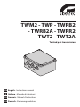
TWM2 - TWP - TWRB2
- TWRB2A - TWRR2
- TWT2 - TWT2A
Twisted pair transmission
EN English - Instructions manual
IT Italiano - Manuale di istruzioni
FR Francais - Manuel d'instructions
DE Deutsch - Bedienungslanleitung
TWM2 - TWP - TWRB2
- TWRB2A - TWRR2
- TWT2 - TWT2A
Twisted pair transmission
EN English - Instructions manual
Contents
ENGLISH
1.1 Typographical conventions................................................................................................................................. 5
2 Notes on copyright and information on trademarks................................................. 5
3 Safety rules.................................................................................................................... 5
4 Identification................................................................................................................. 6
4.1 Product description and type designation.................................................................................................... 6
4.2 Product markings.................................................................................................................................................... 6
5 Preparing the product for use...................................................................................... 6
5.1 Safety precautions before use............................................................................................................................ 6
5.2 Contents and unpacking...................................................................................................................................... 6
5.3 Safely disposing of packaging material.......................................................................................................... 6
6 Installing and assembling............................................................................................. 7
6.1 Installation................................................................................................................................................................. 7
6.1.1 Connections.............................................................................................................................................................................. 7
6.2 Configuration............................................................................................................................................................ 7
6.2.1 Transmitters............................................................................................................................................................................... 7
6.2.1.1 Active transmitter setup............................................................................................................................................................................ 8
6.2.2 TWP passive transmitter setup........................................................................................................................................... 8
6.2.3 Receivers.................................................................................................................................................................................... 8
6.2.4 Type of cable............................................................................................................................................................................. 9
6.2.4.1 Meaning of the terms...............................................................................................................................................................................10
7 Maintaining and cleaning........................................................................................... 10
8 Disposal of waste materials........................................................................................ 10
9 Technical data.............................................................................................................. 11
9.1 General......................................................................................................................................................................11
9.2 Mechanical...............................................................................................................................................................11
9.3 Electrical...................................................................................................................................................................11
9.4 Environment............................................................................................................................................................11
9.5 Compliance to........................................................................................................................................................11
9.6 Package.....................................................................................................................................................................11
3
EN - English - Instructions manual
1 About this manual......................................................................................................... 5
4
EN - English - Instructions manual
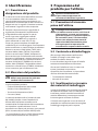
3 Safety rules
Before installing and using this unit,
please read this manual carefully. Be sure
to keep it handy for later reference.
hh
1.1 Typographical conventions
DANGER!
High level hazard.
Risk of electric shock. Disconnect the
power supply before proceeding with any
operation, unless indicated otherwise.
gg
WARNING!
Medium level hazard.
This operation is very important for
the system to function properly. Please
read the procedure described very
carefully and carry it out as instructed.
hh
INFO
Description of system specifications.
We recommend reading this part
carefully in order to understand
the subsequent stages.
jj
The manufacturer declines all responsibility
for any damage caused by an improper use
of the appliances mentioned in this manual.
Furthermore, the manufacturer reserves
the right to modify its contents without
any prior notice. The documentation
contained in this manual has been
collected with great care, the manufacturer,
however, cannot take any liability for
its use. The same thing can be said for
any person or company involved in the
creation and production of this manual.
• The device must be installed only and
exclusively by qualified technical personnel.
• Before any technical work on the appliance,
disconnect the power supply.
• Do not use power supply cables
that seem worn or old.
• Never, under any circumstances, make any
changes or connections that are not shown in
this handbook: improper use of the appliance
can cause serious hazards, risking the safety
of personnel and of the installation.
2 Notes on copyright and
information on trademarks
• Use only original spare parts. Not original
spare parts could cause fire, electrical
discharge or other hazards.
The quoted names of products or companies
are trademarks or registered trademarks.
• Before proceeding with installation check the
supplied material to make sure it corresponds
to the order specification by examining the
identification labels ("4.2 Product markings", page 6).
• Connect the system to a power supply line
that corresponds to the indications on the
data plate ("4.2 Product markings", page 6).
When using the passive transmitter (TWP)
do not supply power to the device.
• The appliance is to be considered OFF only
when the power supply (excluded TWP) is
disconnected and the connection cables
to other devices have been removed.
5
EN - English - Instructions manual
1 About this manual
EN - English - Instructions manual
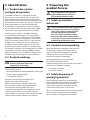
4 Identification
4.1 Product description
and type designation
The video transmission system over twisted
pair consists in a transmitter and a receiver. The
transmitter converts the composite video signal
from a camera and transmit it over twisted pair, then
the receiver converts again the signal in composite
video. Both devices can be adjusted allowing
amplification and equalisation of the signal then
it is possible to cover long distances (up to 1500m
for a colour video signal with UTP Cat. 5e cable).
A wide range of models is available satisfying
any installation requirements. The transmitter is
normally supplied in a IP56 enclosure for outdoor
installation: available in two versions, 12Vdc/24Vac
(TWT2) and 230Vac, 50Hz (TWT2A). A mini version
(TWM2) is also available, fed in low voltage, for
installation in the outdoor camera housing. The
receivers are normally supplied in a IP56 enclosure
for outdoor installation: low voltage version (TWRB2)
12Vdc/24Vac and high voltage (TWRB2A) 230Vac,
50Hz. The receiver is also available on Europe card
(TWRR2), fed in low voltage, for rack installation.
4.2 Product markings
The twisted pair transmitters and
receivers have two labels that
comply with CE marking.
hh
The first label contains:
• Model identification code (Extended 3/9 Bar-code)
• Power supply voltage (Volts)*
• Consumption (Watts)*
The second label shows the model serial
number (Extended 3/9 Bar-code)
Before commencing installation, make sure
the transmitter’s power supply specifications
correspond to those required. The use of
inappropriate equipment may subject personnel
and the system itself to serious safety hazards.
* With the passive transmitter (TWP), the power supply
and the relevant marking data are not provided.
6
5 Preparing the
product for use
Any change that is not expressly
approved by the manufacturer
will invalidate the guarantee.
hh
5.1 Safety precautions
before use
In the 115/230Vac powered configuration
it is necessary to insert a 1 0 unipolar
main switch (open contact distance
d>3mm) upstream on the power
line. This switch should be used to
disconnect the power supply before
carrying out any maintenance operation
or before opening the housing.
gg
5.2 Contents and unpacking
When the product is delivered, make sure that
the package is intact and that there are no
signs that it has been dropped or scratched.
If there are obvious signs of damage,
contact the supplier immediately.
Keep the packaging in case you need
to send the product for repairs.
Check the contents to make sure they correspond
with the list of materials as below:
• Transmitter or receiver
• Instructions manual
5.3 Safely disposing of
packaging material
The packaging material can all be recycled.
The installer technician will be responsible for
separating the material for disposal, and in
any case for compliance with the legislation
in force where the device is to be used.
Bear in mind that if the material has to be returned
due to a fault, using the original packaging
for its transport is strongly recommended.
6 Installing and assembling
When configuring the TWT2A and TWRB2A
models take particular care to prevent
accidental contact between the tool being
used for regulation and the live parts
(230Vac), since the device must be powered
when carrying out the adjustments.
gg
6.1 Installation
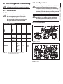
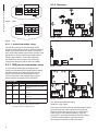
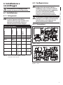
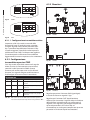
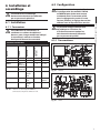
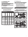
6.1.1 Connections
To make the connections just follow
the arrangement given in the table
below which, for each model, shows
the connector to be used according to
the type of device to be connected.
hh
6.2.1 Transmitters
Model
Camera
Monitor
Twisted pair
Power supply
Connections table
TWP
BNC
---
A B
---
TWM2
BNC
---
A B
AC / DC
TWT2
--GND |
VIDEO IN
A B
AC / DC
TWT2A
GND |
--VIDEO IN
A B
L N
TWRB2
---
GND |
VIDEO
OUT
A B
AC / DC
TWRR2*
---
VIDEO
OUT
A B
POWER
SUPPLY
TWRB2A
---
GND |
VIDEO
OUT
A B
L N
Tab. 01
The configuration procedure makes it
possible to set up the unit for optimum
performance and should only be carried
out by skilled, authorised personnel.
hh
Fig. 01
TWT2A.
Fig. 02
TWT2.
* In the TWRR2 receiver the connectors
are on the back of the rack.
7
EN - English - Instructions manual
Only specialised personnel should be
allowed to install and assemble the device.
hh
6.2 Configuration
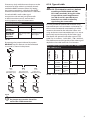
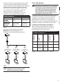
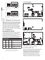
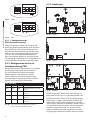
6.2.3 Receivers
EN - English - Instructions manual
ON
1 2 3
A
Fig. 03
B
TWM2.
+
ON
+
+
1 2 3
A
Fig. 04
B
Fig. 05
TWRB2.
Fig. 06
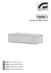
TWRR2.
TWP.
6.2.1.1 Active transmitter setup
Set the dip switches to ON according to the
distance of the cable in order to achieve the best
video signal on the monitor, (bear in mind that
dip1 inserts the lowest equalisation and dip 3 the
greatest; it is also possible to set combinations
of the 3 dip switches). Then, after adjusting
the receiver, it may be necessary to change
slightly the settings made on the transmitter.
6.2.2 TWP passive transmitter setup
It is possible to attenuate the output video
signal (on the terminal for twisted cable) setting
the dip switches according the values on the
table. This function can be required in case
of short distances, with receiver input signal
levels too high and with risk of saturation.
Dip position
Dip1
Dip2
Dip3
V terminal output
ON
ON
ON
Vout (twisted)= V in (coax)
x 1.15
OFF
ON
ON
Vout (twisted)= V in (coax) x
1.15 / 2
OFF
OFF
ON
Vout (twisted)= V in (coax) x
1.15 / 3
OFF
OFF
OFF
Vout (twisted)= V in (coax) x
1.15 / 4
Tab. 02
8
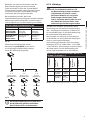
In case of using the TWP as passive receiver,
set all dip switches to “ON” position.
+
Fig. 07
+
+
TWRB2A.
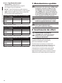
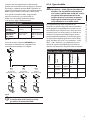
First adjust the GAIN trimmer to
achieve a 1 Vpp signal.
Then adjust the DIST trimmer (distance equalisation)
to reconstruct the video signal according to the
distance (check the signal using an oscilloscope).
If the signal is over-compensated try again by
turning OFF some dip switches on the transmitter;
if under-compensated try again by turning
ON some dip switches on the transmitter.
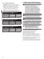
6.2.4 Type of cable
The type of cable to be used is a Cat. 5e
UTP (Unshielded Twisted Pair) (defined
according to TIA/EIA 568A and ISO/
IEC 11801 standards). Using this cable
it is possible to cover long distances
(see Tab.2) and it is possible to pass
more than one video or telemetry
signal along the same cable.
hh
If used with MDI, set for video signal
transmission over twisted pair (please refer
to MDI instruction manual), remove the J1
and J2 jumper to adjust the attenuation.
RED LED OR “
LEVEL OUT ”
OR “LEVEL”
High quality video Low quality or no
signal
video signal
Tab. 03
By opening the jumper indicated by caption
BALANCE, up to 3 receivers can be connected
in cascade as shown in the picture.
A-B
RX 1
A-B
Not terminated
(BALANCE open)
RX 2
A-B
Not terminated
(BALANCE open)
The device also operates with other types of UTP
cable (Cat. 2 or above - 18/24 AWG – 100 ± 20 Ohm).
The performance and the quality of the video signal
depend on the cable itself and on its location.
Main characteristics of a Cat. 5e – 100 Ohm - 24
AWG cable at 20 °C
100 ± 15
ohm
21 dB/km
@ 1 Mhz
62 dB/km
@ 1 Mhz
192 ohm/
km
43 dB/km
@ 4 Mhz
53 dB/km
@ 4 Mhz
65 db/km
@10 Mhz
47 dB/
km @ 10
Mhz
RX 1
A-B
Terminated
(BALANCE closed)
Tab. 04
Video OUT
Video OUT
Insulation
Powered correctly Power supply
absent
Loop resistance
(max.)
GREEN LED OR
“PW ON”
OR “POWER”
It is also possible to increase the distances using
intermediate pairs of transmitters and receivers. In
this case we recommend not exceeding ¾ of the
maximum distance for the individual sector and
using at the most one intermediate pair so as not to
excessively impair the quality of the video signal.
N.E.X.T. (min)
OFF
Attenuation
(max.)
ON
Impedance
(1-100 MHz)
meaning of the LED’s
EN - English - Instructions manual
If necessary (only with distances close to or at the
maximum or when colour is practically absent)
enable the BURST trimmer (colour) by setting
the jumper at position A, and adjust the BURST
trimmer until the best possible colour is obtained.
PE
Cat. 5e – 100 Ohm UTP cable characteristics.
Video OUT
Fig. 08
On the last receiver of the chain
the jumper must remain closed. Do
not use the STUB connection.
jj
9
6.2.4.1 Meaning of the terms
EN - English - Instructions manual
• Attenuation - Represents the decrease in
amplitude of a signal travelling along a conductor
• N.E.X.T. - Near-End Xtalk (Crosstalk), indicates
how much one signal interferes with another
• AWG -American Wire Gauge, American
system for measuring cable diameter.
Maximum performance with 4x2x24AWG Cat. 5e
– 100 Ohm UTP cable
COLOUR
B/W
1500m
2000m
4 VIDEO SIGNALS 1500m
1500m
1 VIDEO SIGNAL
Tab. 05
Maximum performance.
Maximum performance with UTP 4x2x24AWG
Cat. 5e – 100 Ohm cable
COLOUR
B/W
1 VIDEO SIGNAL
350m
600m
4 VIDEO SIGNAL
350m
600m
Tab. 06
Transmitter TWP, receiver TWP.
Maximum performance with UTP 4x2x24AWG
Cat. 5e – 100 Ohm cable
COLOUR
B/W
1 VIDEO SIGNAL
750m
1250m
4 VIDEO SIGNAL
750m
1250m
Tab. 07
Transmitter TWP, receiver and TWRR2/TWRB2/TWRB2A.
7 Maintaining and cleaning
We recommend using it connected
directly to the camera (TWM2,TWP) or
resting on a solid base (versions with
IP box) or firmly screwed down to a box
rack (TWRR2), with the power supply and
connection cables positioned so as not to
get in the way of the operator and without
being subjected to stresses and twists.
hh
When using the TWM2 transmitter
inside housings located in particular
hot environments it is recommended
to use the 12Vdc power supply.
hh
For the versions with the IP56
box use the supplied plugs to
ensure complete insulation.
hh
8 Disposal of waste
materials
This symbol mark and recycle system
are applied only to EU countries
and not applied to the countries
in the other area of the world.
nn
Your product is designed and manufactured
with high quality materials and components
which can be recycled and reused.
This symbol means that electrical and electronic
equipment, at their end-of-life, should be disposed
of separately from your household waste.
Please dispose of this equipment at your local
Community waste collection or Recycling centre.
In the European Union there are separate collection
systems for used electrical and electronic products.
10
9.3 Electrical
9.1 General
Transmitter video input: 1.0Vpp, 75 Ohm
Immunity to ground loops
Receiver video input: 0.05Vpp - 0.55Vpp
Protection against over voltage
Receiver video output: 1.0Vpp - 2.5Vpp
Active transmitters: TWM2, TWT2, TWT2A
Transmitter video output impedance: 110 Ohm
Active receivers: TWRR2, TWRB2, TWRB2A
Receiver video input impedance: 100 Ohm±10%
Passive transmitter and receiver: TWP, TWPL1
Max distance with UTP Cat. 5e
Power supply TWT2 / TWM2 / TWRB2 / TWRR2:
12Vdc/24Vac
Active transmitter and receiver
Power supply TWT2A / TWRB2A: 230Vac
Transmitter video output: 2x0.5Vpp
-- 1500m (4921ft) colour signal
Consumption max: 2W
-- 2000m (6561ft) white / black signal
Power pass through TWPL1: 250mA at 300m, 1A at 30m
on AWG24 cables
Passive transmitter and receiver
-- 350m (1148ft) colour signal
-- 600m (1968ft) white / black signal
Passive transmitter TWP and receiver TWRR2, TWRB2,
TWRB2A
-- 750m (2460ft) colour signal
-- 1250m (4101ft) white / black signal
Passive transmitter and receiver TWPL1
-- 100m (328ft) colour signal
Passive transmitter TWPL1 and active receiver TWR
-- 750m (2460ft) colour signal
Supplied with instruction manual
Retrofit on previous models: contact VIDEOTEC for further specifications.
9.2 Mechanical
TWP - TWM2
Dimensions: 40x25x63mm (1.6x0.9x2.5in) connector not
included
Used cable UTP Cat. 5e or above, 24AWG, 100 Ohm
9.4 Environment
Indoor / Outdoor for TWT2, TWRB2, TWT2A and TWRB2A
Indoor for TWP, TWPL1, TWM2 and TWRR2
Operating temperature: -10°C / +50°C (14°F / 122 F°) for
TWM2, TWT2, TWRB2, TWT2A e TWRB2A
Operating temperature: -20°C / +75°C (-4°F / 167°F) per
TWP
Operating temperature for TWPL1: 0°C / + 85°C (32°F /
+185°F)
9.5 Compliance to
CE according to EN 61000-6-3, EN 60950, EN 50130-4
TWT2, TWRB2, TWT2A and TWRB2A: IP56
9.6 Package
Unit Weight:
TWPL1
TWM2
0.1kg / 0.2lb
Dimensions: 22x47x32mm (0.87x1.85x1.26in) connector
and cable not included
TWT2 / TWT2A
0.1kg / 0.2lb
TWRB2 / TWRB2A
0.2kg / 0.4lb
TWT2 - TWRB2 - TWT2A - TWRB2A
TWRR2
0.1kg / 0.2lb
Plastic enclosure
TWP
0.1kg / 0.2lb
Dimensions: 129x89x58mm (5x3.5x2.3in) cable-glands
not included
TWRR2
Dimensioni: 3Ux6TEx190mm (7.5in) Eurocard
11
EN - English - Instructions manual
9 Technical data
VIDEOTEC S.p.A.
www.videotec.com
Printed in Italy
MNVCTW2_0913_EN
TWM2 - TWP - TWRB2
- TWRB2A - TWRR2
- TWT2 - TWT2A
Trasmissione video bifilare
IT Italiano - Manuale di istruzioni
Sommario
ITALIANO
1 Informazioni sul presente manuale............................................................................. 5
1.1 Convenzioni tipografiche..................................................................................................................................... 5
4.1 Descrizione e designazione del prodotto...................................................................................................... 6
4.2 Marcatura del prodotto......................................................................................................................................... 6
5 Preparazione del prodotto per l’utilizzo..................................................................... 6
5.1 Precauzioni di sicurezza prima dell’utilizzo................................................................................................... 6
5.2 Contenuto e disimballaggio................................................................................................................................ 6
5.3 Smaltimento in sicurezza dei materiali di imballaggio.............................................................................. 6
6 Installazione e assemblaggio....................................................................................... 7
6.1 Installazione.............................................................................................................................................................. 7
6.1.1 Collegamenti............................................................................................................................................................................ 7
6.2 Configurazione......................................................................................................................................................... 7
6.2.1 Trasmettitori.............................................................................................................................................................................. 7
6.2.1.1 Configurazione trasmettitore attivo...................................................................................................................................................... 8
6.2.2 Configurazione trasmettitore passivo TWP................................................................................................................... 8
6.2.3 Ricevitori..................................................................................................................................................................................... 8
6.2.4 Tipo di cavo............................................................................................................................................................................... 9
6.2.4.1 Significato dei termini..............................................................................................................................................................................10
7 Manutenzione e pulizia.............................................................................................. 10
8 Smaltimento dei rifiuti................................................................................................ 10
9 Dati tecnici................................................................................................................... 11
9.1 Generale...................................................................................................................................................................11
9.2 Meccanica................................................................................................................................................................11
9.3 Elettrico.....................................................................................................................................................................11
9.4 Ambiente..................................................................................................................................................................11
9.5 Conformità...............................................................................................................................................................11
9.6 Imballaggio.............................................................................................................................................................11
3
IT - Italiano - Manuale di istruzioni
2 Note sul copyright e informazioni sui marchi commerciali....................................... 5
3 Norme di sicurezza........................................................................................................ 5
4 Identificazione............................................................................................................... 6
4
IT - Italiano - Manuale di istruzioni
1 Informazioni sul
presente manuale
1.1 Convenzioni tipografiche
PERICOLO!
Pericolosità elevata.
Rischio di scosse elettriche. Togliere
l'alimentazione prima di procedere con
le operazioni, salvo diversa indicazione.
gg
ATTENZIONE!
Pericolosità media.
L'operazione è molto importante per
il corretto funzionamento del sistema.
Si prega di leggere attentamente
la procedura indicata e di eseguirla
secondo le modalità previste.
hh
INFO
Descrizione delle caratteristiche del
sistema.
Si consiglia di leggere attentamente
per comprendere le fasi successive.
jj
2 Note sul copyright
e informazioni sui
marchi commerciali
I nomi di prodotto o di aziende citati sono
marchi commerciali o marchi commerciali
registrati appartenenti alle rispettive società.
Il produttore declina ogni responsabilità
per eventuali danni derivanti da un
uso improprio delle apparecchiature
menzionate in questo manuale. Si
riserva inoltre il diritto di modificarne il
contenuto senza preavviso. Ogni cura è
stata posta nella raccolta e nella verifica
della documentazione contenuta in
questo manuale, tuttavia il produttore
non può assumersi alcuna responsabilità
derivante dall'utilizzo della stessa.
Lo stesso dicasi per ogni persona o
società coinvolta nella creazione e
nella produzione di questo manuale.
hh
IT - Italiano - Manuale di istruzioni
Prima di installare e utilizzare questa unità, leggere
attentamente questo manuale. Conservare questo
manuale a portata di mano come riferimento futuro.
3 Norme di sicurezza
• L'installazione e la manutenzione del
dispositivo deve essere eseguita solo
da personale tecnico qualificato.
• Prima di effettuare interventi tecnici
sull'apparecchio togliere l'alimentazione elettrica.
• Non utilizzare cavi di alimentazione con
segni di usura o invecchiamento.
• Non effettuare per nessun motivo
alterazioni o collegamenti non previsti in
questo manuale: l'uso di apparecchi non
idonei può portare a gravi pericoli per la
sicurezza del personale e dell'impianto.
• Utilizzare solo parti di ricambio originali. Pezzi
di ricambio non originali potrebbero causare
incendi, scariche elettriche o altri pericoli.
• Prima di procedere con l'installazione controllare
che il materiale fornito corrisponda alle specifiche
richieste esaminando le etichette di marcatura
("4.2 Marcatura del prodotto", pagina 6).
• Collegare ad una linea di alimentazione
corrispondente a quella indicata sulle etichette
di marcatura ("4.2 Marcatura del prodotto",
pagina 6). Nel caso di trasmettitori passivi (TWP),
non fornire alimentazione al dispositivo.
• L’apparecchio si considera disattivato
soltanto quando l’alimentazione é disinserita
(escluso TWP) e i cavi di collegamento
con altri dispositivi sono stati rimossi.
5
4 Identificazione
IT - Italiano - Manuale di istruzioni
4.1 Descrizione e
designazione del prodotto
Il sistema di trasmissione video bifilare consiste
in un trasmettitore video che accetta un
segnale video composito proveniente da una
telecamera e lo converte per essere trasmesso su
doppini twistati. In seguito il ricevitore converte
nuovamente il segnale in video composito.
Entrambi i dispositivi hanno la possibilità di
regolazione permettendo l’amplificazione
e l’equalizzazione del segnale. In questo
modo si possono raggiungere notevoli
distanze (fino a 1500m con un segnale a
colori utilizzando un cavo UTP Cat. 5e).
Esiste una gamma completa di modelli per
soddisfare le più svariate esigenze. Il trasmettitore
può essere fornito su scatola IP56 per installazioni
esterne in versione 12Vdc/24Vac (TWT2) ed in
versione 230Vac, 50Hz (TWT2A). Disponibile
anche in versione mini (TWM2), alimentato in
bassa tensione, per l’installazione nella custodia
da esterno. Ugualmente i ricevitori possono essere
forniti su scatola IP56 per installazioni esterne in
versione 12Vdc/24Vac (TWRB2) ed in versione
230Vac, 50Hz (TWRB2A). È disponibile inoltre il
ricevitore su scheda Europa (TWRR2), alimentato
in bassa tensione, per installazione a rack.
4.2 Marcatura del prodotto
Sui trasmettitori e ricevitori video
bifilari sono riportate due etichette
conformi alla marcatura CE.
5 Preparazione del
prodotto per l’utilizzo
Qualsiasi cambiamento non
espressamente approvato dal
costruttore fa decadere la garanzia.
hh
5.1 Precauzioni di sicurezza
prima dell’utilizzo
In configurazione alimentata a
115/230Vac occorre inserire sulla linea di
alimentazione, a monte, un interruttore
generale unipolare 1 0 (distanza apertura
dei contatti d>3mm). Tale interruttore
deve essere utilizzato come mezzo di
separazione dell’alimentazione prima
di eseguire qualsiasi operazione di
manutenzione o apertura della custodia.
gg
5.2 Contenuto e disimballaggio
Alla consegna del prodotto verificare che
l'imballo sia integro e non abbia segni
evidenti di cadute o abrasioni.
In caso di evidenti segni di danno all'imballo
contattare immediatamente il fornitore.
Conservare l'imballo nel caso sia necessario
inviare il prodotto in riparazione.
Controllare che il contenuto sia rispondente
alla lista del materiale sotto indicata:
hh
• Trasmettitore o ricevitore
La prima etichetta contiene:
5.3 Smaltimento in sicurezza
dei materiali di imballaggio
• Codice di identificazione del modello
(Codice a barre Extended 3/9 )
• Tensione di alimentazione (Volt)*
• Consumo (Watt)*
La seconda etichetta indica il numero di serie
del modello (codice a barre Extended 3/9).
All’atto dell’installazione controllare se le
caratteristiche di alimentazione del trasmettitore
corrispondano a quelle richieste. L’uso di
apparecchi non idonei può portare a gravi pericoli
per la sicurezza del personale e dell’impianto.
* In caso di dispositivi passivi (TWP) l’alimentazione
e relativi dati di marcatura non sono previsti.
6
• Manuale di istruzioni
I materiali d'imballo sono costituiti interamente
da materiale riciclabile. Sarà cura del tecnico
installatore smaltirli secondo le modalità di
raccolta differenziata o comunque secondo
le norme vigenti nel Paese di utilizzo.
Si ricorda comunque che in caso di ritorno di
materiale con malfunzionamenti è consigliato
l'imballaggio originale per il trasporto.
6 Installazione e
assemblaggio
6.2 Configurazione
L'installazione e l'assemblaggio vanno
eseguiti solo da personale specializzato.
hh
Prestare particolare attenzione nella
configurazione dei modelli TWT2A e
TWRB2A per evitare contatti accidentali
tra l’utensile utilizzato per la regolazione
e le parti in alta tensione (230Vac)
dato che la regolazione deve essere
eseguita con il dispositivo alimentato.
gg
6.1.1 Collegamenti
Per i collegamenti basta seguire
lo schema riportato nella tabella
sottostante dove per ogni modello viene
riportato il connettore da utilizzare a
seconda del dispositivo da collegare.
hh
La procedura di configurazione consente di
predisporre l’unità per un funzionamento
ottimale e deve essere effettuata solo
da personale tecnico qualificato.
hh
6.2.1 Trasmettitori
Modello
Telecamera
Monitor
Doppino
Bifilare
Alimentazione
Tabella collegamenti
TWP
BNC
---
A B
---
TWM2
BNC
---
A B
AC / DC
TWT2
--GND |
VIDEO IN
A B
AC / DC
TWT2A
GND |
--VIDEO IN
A B
L N
TWRB2
---
GND |
VIDEO
OUT
A B
AC / DC
TWRR2*
---
VIDEO
OUT
A B
POWER
SUPPLY
TWRB2A
---
GND |
VIDEO
OUT
A B
L N
Tab. 01
Fig. 01
TWT2A.
Fig. 02
TWT2.
* Nel caso del ricevitore TWRR2 i connettori
sono posti nel retro del rack.
7
IT - Italiano - Manuale di istruzioni
6.1 Installazione
6.2.3 Ricevitori
ON
1 2 3
IT - Italiano - Manuale di istruzioni
A
Fig. 03
B
TWM2.
+
ON
+
+
1 2 3
A
Fig. 04
B
Fig. 05
TWRB2.
Fig. 06
TWRR2.
TWP.
6.2.1.1 Configurazione trasmettitore attivo
Impostare a ON i dip switch a seconda della
distanza del cavo in modo da avere a monitor
il miglior segnale video, (tenere presente che il
dip 1 introduce l’equalizzazione minore e il dip
3 quella maggiore; è possibile anche impostare
combinazioni dei 3 dip). Poi dopo avere regolato
il ricevitore potrà essere necessario modificare
leggermente la taratura impostata sul trasmettitore.
6.2.2 Configurazione
trasmettitore passivo TWP
Con i dip-switch è possibile attenuare il segnale
video di uscita (su morsetto per cavo twistato)
secondo i valori riportati in tabella. Questa
funzione può essere necessaria in caso di brevi
distanze, con segnale d’ingresso del ricevitore a
livelli troppo alti e con rischio di saturazione.
Posizione dip
Dip1
Dip2
Dip3
V uscita su morsetto
ON
ON
ON
Vout (twisted)= V in (coax)
x 1.15
OFF
ON
ON
Vout (twisted)= V in (coax) x
1.15 / 2
OFF
OFF
ON
Vout (twisted)= V in (coax) x
1.15 / 3
OFF
OFF
OFF
Vout (twisted)= V in (coax) x
1.15 / 4
Tab. 02
8
Nel caso in cui si usi il TWP come ricevitore passivo, è
necessario settare tutti i dip-switch nella posizione “ON”.
+
Fig. 07
+
+
TWRB2A.
Regolare per primo il trimmer GAIN (guadagno)
in modo da avere un segnale 1 Vpp.
Regolare poi il trimmer DIST (equalizzazione
distanza) per ricostruire il segnale video in funzione
della distanza (controllare con un oscilloscopio il
segnale). Se il segnale risulta troppo compensato
riprovare portando in OFF alcuni dip sul
trasmettitore; se risulta poco compensato riprovare
portando in ON alcuni dip del trasmettitore.
6.2.4 Tipo di cavo
Il tipo di cavo da utilizzare è un cavo UTP
(Unshielded Twisted Pair) Cat. 5e (definito
secondo gli standard TIA/EIA 568A e ISO/
IEC 11801). Con questo cavo si possono
coprire lunghe distanze (vedi Tab.2) ed
è possibile far passare più segnali video
o di telemetria nello stesso cavo.
hh
Alimentazione
corretta
Mancanza di
alimentazione
LED ROSSO O
“LEVEL OUT”
O “LEVEL”
Buon livello del
segnale video
presente
Scarso livello
o assenza del
segnale video
Tab. 03
Aprendo il jumper indicato dalla dicitura
BALANCE è possibile collegare fino a 3
ricevitori in cascata come indicato in figura.
A-B
RX 1
A-B
Non terminato
(BALANCE aperto)
RX 2
A-B
Non terminato
(BALANCE aperto)
Il dispositivo funziona anche con altri tipi di
cavo UTP (Cat. 2 o superiore - 18/24 AWG –
100 ± 20 Ohm) ma le prestazioni e la qualità
del segnale video dipendono dal cavo stesso
e dall’ambiente in cui il cavo è steso.
Principali caratteristiche di un cavo di Cat. 5e
– 100 Ohm - 24 AWG a 20 °C
Resistenza di
loop (max)
LED VERDE O
“PW ON”
O “POWER”
È anche possibile aumentare le distanze con l’uso
di coppie di trasmettirori e ricevitori intermedie,
in questo caso si consiglia di non superare i ¾
della distanza massima per la singola tratta e di
utilizzare al massimo una coppia intermedia per non
pregiudicare troppo la qualità del segnale video.
N.E.X.T. (min)
SPENTO
Attenuazione
(max)
ACCESO
Impedenza
(1-100 MHz)
Significato dei LED
100 ± 15
ohm
21 dB/km
@ 1 Mhz
62 dB/km
@ 1 Mhz
192 ohm/
km
43 dB/km
@ 4 Mhz
53 dB/km
@ 4 Mhz
65 db/km
@10 Mhz
47 dB/
km @ 10
Mhz
RX 1
A-B
Terminato
(BALANCE chiuso)
Tab. 04
Video OUT
Video OUT
IT - Italiano - Manuale di istruzioni
Se si utilizzano le minidome MDI, configurate
per la trasmissione su cavo twistato (far
riferimento al manuale della MDI), rimuovere i
jumper J1 e J2 per regolare l'attenuazione.
Isolamento
Se necessario (solo con distanze prossime a quelle
massime o quando il colore risulta praticamente
assente) abilitare il trimmer BURST (colore) mettendo
sulla posizione A il jumper e regolare il trimmer
BURST fino ad ottenere il miglior colore possibile.
PE
Caratteristiche cavo UTP Cat. 5e – 100 Ohm.
Video OUT
Fig. 08
Sull'ultimo ricevitore della catena il
jumper devo rimanere chiuso. Non
utilizzare la connessione STUB.
jj
9
6.2.4.1 Significato dei termini
IT - Italiano - Manuale di istruzioni
• Attenuazione - Rappresenta il
decremento dell’ampiezza di un segnale
che viaggia lungo un conduttore
• N.E.X.T. - Near-End Xtalk (Crosstalk) o diafonia,
indica quanto un segnale disturba un altro segnale
• AWG - American Wire Gauge, sistema americano
di misurazione del diametro dei cavi.
Prestazioni massime con cavo UTP 4x2x24AWG
Cat. 5e – 100 Ohm
COLORE
B/N
1500m
2000m
4 SEGNALI VIDEO 1500m
1500m
1 SEGNALE
VIDEO
Tab. 05
Prestazioni massime con cavo UTP 4x2x24AWG
Cat. 5e – 100 Ohm
COLORE
B/N
350m
600m
4 SEGNALI VIDEO 350m
600m
Tab. 06
Trasmettitore TWP, ricevitore TWP.
Prestazioni massime con cavo UTP 4x2x24AWG
Cat. 5e – 100 Ohm
COLORE
B/N
750m
1250m
4 SEGNALI VIDEO 750m
1250m
1 SEGNALE
VIDEO
Tab. 07
Si raccomanda di utilizzarlo collegato
direttamente alla telecamera (TWM2,TWP)
o poggiato su una base solida (versioni
su scatola IP) o ben avvitato sul cestello
rack (TWRR2), con i cavi di alimentazione
e di collegamento in posizione tale da non
essere di intralcio all’operatore e che non
siano sottoposti a tensioni o torsioni.
hh
Se si usa il trasmettitore TWM2 all’interno
di custodie in ambienti particolarmente
caldi è consigliato alimentarlo a 12Vdc.
hh
Utilizzare nelle versioni su scatola
IP56 i tappi in dotazione per
garantire l’isolamento completo.
hh
Prestazioni massime.
1 SEGNALE
VIDEO
7 Manutenzione e pulizia
Trasmettitore TWP, ricevitore e TWRR2/TWRB2/TWRB2A.
8 Smaltimento dei rifiuti
Questo simbolo e il sistema di
riciclaggio sono validi solo nei paesi
dell'EU e non trovano applicazione
in altri paesi del mondo.
nn
Il vostro prodotto è stato costruito da
materiali e componenti di alta qualità,
che sono riutilizzabili o riciclabili.
Prodotti elettrici ed elettronici che portano
questo simbolo alla fine dell'uso devono essere
smaltiti separatamente dai rifiuti casalinghi.
Vi preghiamo di smaltire questo apparecchio
in un Centro di raccolta o in un'Ecostazione.
Nell'Unione Europea esistono sistemi di raccolta
differenziata per prodotti elettrici ed elettronici.
10
9 Dati tecnici
9.3 Elettrico
9.1 Generale
Ingresso video trasmettitore: 1.0Vpp, 75 Ohm
Immunità ai loop di terra
Ingresso video ricevitore: 0.05Vpp - 0.55Vpp
Protezione da sovratensioni
Uscita video ricevitore: 1.0Vpp - 2.5 Vpp
Trasmettitori attivi: TWM2, TWT2, TWT2A
Impedenza d’uscita trasmettitore: 110 Ohm
Ricevitori attivi: TWRR2, TWRB2, TWRB2A
Impedenza d’ingresso ricevitore: 100 Ohm±10%
Trasmettitore e ricevitore passivo: TWP, TWPL1
Distanza massima con cavo UTP Cat. 5e
Alimentazione TWT2 / TWM2 / TWRB2 / TWRR2:
12Vdc/24Vac
Trasmettitore e ricevitore attivi
Alimentazione TWT2A / TWRB2A: 230Vac
Uscita video trasmettitore: 2x0.5Vpp
Consumo massimo: 2W
-- 2000m segnale bianco e nero
Alimentazione passante TWPL1: 250mA a 300m, 1A a
35m su cavi AWG24
Trasmettitore passivo e ricevitore passivo
-- 350m segnale a colori
-- 600m segnale bianco nero
Trasmettitore passivo TWP e ricevitore TWRR2, TWRB2,
TWRB2A
-- 750m segnale a colori
-- 1250m segnale bianco nero
Trasmettitore e ricevitore passivo TWPL1
-- 100m segnale colore
Trasmettitore passivo TWPL1 e ricevitore attivo TWR
-- 750m segnale colore
Utilizzare cavo UTP Cat. 5e o superiore, 24AWG, 100 Ohm
9.4 Ambiente
Interno / Esterno per TWT2, TWRB2, TWT2A e TWRB2A
Interno per TWP, TWPL1, TWM2 e TWRR2
Temperatura di esercizio: -10°C / +50°C per TWM2, TWT2,
TWRB2, TWT2A e TWRB2A
Temperatura di esercizio: -20°C / +75°C per TWP
Temperatura di esercizio per TWPL1: 0°C / + 85°C
9.5 Conformità
Forniti con manuale d’istruzione
CE in accordo con EN 61000-6-3, EN 60950, EN 50130-4
Retrofit su prodotti fuori produzione: contattare VIDEOTEC per ulteriori
specifiche.
IP56: TWT2, TWRB2, TWT2A e TWRB2A
9.2 Meccanica
TWP - TWM2
Dimensioni: 40x25x63mm (connettore escluso)
TWPL1
Dimensioni: 22x47x32mm (connettore e cavo escluso)
TWT2 - TWRB2 - TWT2A - TWRB2A
Scatola in materiale plastico
9.6 Imballaggio
Peso Unitario:
TWM2
0.1kg
TWT2 / TWT2A
0.1kg
TWRB2 / TWRB2A
0.2kg
TWRR2
0.1kg
TWP
0.1kg
Dimensioni: 129x89x58mm (esclusi pressacavi)
TWRR2
Dimensioni: 3Ux6TEx190mm Eurocard
11
IT - Italiano - Manuale di istruzioni
-- 1500m segnale a colori
VIDEOTEC S.p.A.
www.videotec.com
Printed in Italy
MNVCTW2_0913_IT
TWM2 - TWP - TWRB2
- TWRB2A - TWRR2
- TWT2 - TWT2A
Transmission vidéo bifilaire
FR Français - Manuel d'instructions
Sommaire
FRANÇAIS
1 À propos de ce mode d’emploi..................................................................................... 5
1.1 Conventions typographiques............................................................................................................................. 5
4.1 Description et désignation du produit............................................................................................................ 6
4.2 Marquage du produit............................................................................................................................................ 6
5 Préparation du produit en vue de l’utilisation............................................................ 6
5.1 Précautions de sécurité avant l’utilisation...................................................................................................... 6
5.2 Contenu et déballage............................................................................................................................................ 6
5.3 Élimination sans danger des matériaux d’emballage................................................................................ 6
6 Installation et assemblage............................................................................................ 7
6.1 Installation................................................................................................................................................................. 7
6.1.1 Connexions................................................................................................................................................................................ 7
6.2 Configuration............................................................................................................................................................ 7
6.2.1 Transmetteurs........................................................................................................................................................................... 7
6.2.1.1 Configuration transmetteur actif:.......................................................................................................................................................... 8
6.2.2 Configuration transmetteur passif TWP.......................................................................................................................... 8
6.2.3 Récepteurs................................................................................................................................................................................. 8
6.2.4 Type de câble............................................................................................................................................................................ 9
6.2.4.1 Signification des termes utilisés:...........................................................................................................................................................10
7 Entretien et nettoyage................................................................................................ 10
8 Élimination des déchets.............................................................................................. 10
9 Données techniques.................................................................................................... 11
9.1 Généralités...............................................................................................................................................................11
9.2 Mécanique...............................................................................................................................................................11
9.3 Électrique.................................................................................................................................................................11
9.4 Environnement......................................................................................................................................................11
9.5 En conformité avec...............................................................................................................................................11
9.6 Emballage................................................................................................................................................................11
3
FR - Francais - Manuel d'instructions
2 Notes sur le copyright et informations sur les marques de commerce..................... 5
3 Normes de securité........................................................................................................ 5
4 Identification................................................................................................................. 6
4
FR - Francais - Manuel d'instructions
1 À propos de ce
mode d’emploi
Avant d’installer et d’utiliser cet appareil,
veuillez lire attentivement ce mode d’emploi.
Conservez-le à portée de main pour pouvoir
vous y reporter en cas de besoin.
DANGER!
Risque élevé.
Risque de choc électrique. Sauf indication
contraire, sectionner l’alimentation
avant de procéder à toute opération.
gg
ATTENTION!
Risque moyen.
Opération extrêmement importante
en vue d’un fonctionnement correct du
système; lire avec attention les opérations
indiquées et s’y conformer rigoureusement.
hh
REMARQUE
Description des caractéristiques du
système.
Il est conseillé de procéder à une
lecture attentive pour une meilleure
compréhension des phases suivantes.
jj
2 Notes sur le copyright
et informations sur les
marques de commerce
Les noms de produit ou de sociétés cités
sont des marques de commerce ou des
marques de commerce enregistrées.
Le producteur décline toute responsabilité
pour les dommages éventuels dus à une
utilisation non appropriée des appareils
mentionnés dans ce manuel. On réserve
en outre le droit d’en modifier le contenu
sans préavis. La documentation contenue
dans ce manuel a été rassemblée et vérifiée
avec le plus grand soin, cependant, le
producteur ne peut pas s’assumer aucune
responsabilité dérivante de l’emploi de
celle là. La même chose vaut pour chaque
personne ou société impliquées dans la
création et la production de ce manuel.
hh
• L’installation et l’entretien du dispositif
doivent être exclusivement être effectués
par un personnel technique qualifié.
• Sectionner l’alimentation électrique avant
toute intervention technique sur l’appareil.
• Ne pas utiliser de câbles d’alimentation
usés ou endommagés.
• Ne procéder sous aucun prétexte à des
modifications ou des connexions non prévues
dans ce manuel: l’utilisation d’appareils non
adéquats peut comporter des dangers graves
pour la sécurité du personnel et de l’installation.
• Utiliser uniquement des pièces de rechange
d’origine. Les pièces non d’origine peuvent être
source d’incendies, de choc électrique ou autres.
• Avant de procéder à l’installation, contrôler
que le matériel fourni correspond à la
commande et examiner les étiquettes de
marquage ("4.2 Marquage du produit", page 6).
• Connecter les appareils du système à une
ligne d'alimentation correspondant aux
indications des étiquettes de marquage
correspondantes ("4.2 Marquage du produit",
page 6). Avec les transmetteurs passifs TWP,
il ne faut pas alimenter le dispositif.
• L'appareil ne peut être considéré comme
désactivé que si l'alimentation (à l’exception
du TWP) est coupée et les câbles de connexion
aux autres dispositifs déconnectés.
5
FR - Francais - Manuel d'instructions
1.1 Conventions typographiques
3 Normes de securité
4 Identification
FR - Francais - Manuel d'instructions
4.1 Description et
désignation du produit
Le système de transmission vidéo bifilaire est
composé, d'une part, d'un transmetteur qui
transforme le signal vidéo composite sur câble
coaxial en signal symétrique sur paire torsadée
et d'autre part d'un récepteur qui reconvertit
le signal symétrisé en vidéo composite.
Les deux appareils permettent de nombreux
réglages permettant l'amplification et la
symétrisation du signal. Il est ainsi possible de gérer
des distances importantes (max 1500m avec un
signal couleur en utilisant un câble UTP Cat. 5e).
Une gamme complète de modèles est prévue
pour répondre aux exigences les plus diverses. Le
transmetteur existe en boîtier IP56 pour installations
exterieures, en version 12Vdc/24Vac (TWT2) et en
version 230Vac, 50Hz (TWT2A). Le modèle (TWM2),
alimenté en 12Vdc/24Vac se raccorde directement
sur la prise BNC de la caméra. Les récepteurs en
boîtier IP56 existent en version 12Vdc/24Vac
(TWRB2) et 230Vac, 50Hz (TWRB2A). Le récepteur
est également disponible en carte Europa (TWRR2),
alimenté en basse tension pour installation sur rack.
4.2 Marquage du produit
Sur les transmetteurs et récepteurs
vidéo bifilaires sont appliquées deux
étiquettes conformes au marquage CE.
hh
La première étiquette indique:
• Le code d'identification du modèle
(Code barres Extended 3/9 )
• La tension d'alimentation (Volts)*
• La consommation (Watts)*
La seconde étiquette indique le numéro de
série du modèle (Code barres Extended 3/9).
Lors de l'installation, contrôler que les caractéristiques
d'alimentation du récepteur correspondent aux
caractéristiques nécessaires. L'utilisation d'appareils
non adéquats peut comporter des risques graves
pour le matériel et pour la sécurité du personnel.
* Avec les dispositifs passifs (TWP) l’alimentation et les
relatives données de marquage ne sont pas prévues.
6
5 Préparation du produit
en vue de l’utilisation
Toute modification non approuvée
expressément par le fabricant entraînera
l’annulation de la garantie.
hh
5.1 Précautions de sécurité
avant l’utilisation
En cas d’alimentation à 115/230Vac,
installer en amont de la ligne
d’alimentation un interrupteur général
unipolaire 1 0 (distance d’ouverture
des contacts d>3mm). Cet interrupteur
doit être utilisé comme moyen de
séparation de l’alimentation avant
de procéder à l’ouverture du caisson
ou à toute opération d’entretien.
gg
5.2 Contenu et déballage
Lors de la livraison du produit, vérifier que
l’emballage est en bon état et l’absence de
tout signe évident de chute ou d’abrasion.
En cas de dommages évidents, contacter
immédiatement le fournisseur.
Conserver l’emballage en cas de nécessité
d’expédition du produit pour réparation.
Contrôler que le contenu correspond à la
liste matériel indiquée ci-dessous:
• Transmetteur ou récepteur
• Manuel d'instructions
5.3 Élimination sans danger
des matériaux d’emballage
Le matériel d’emballage est entièrement composé
de matériaux recyclables. Le technicien chargé de
l’installation est tenu de l’éliminer conformément aux
dispositions en matière de collecte sélective et selon
les normes en vigueur dans le pays d’utilisation.
En cas de dysfonctionnement et de retour
de matériel , il est conseillé d’utiliser
l’emballage original pour le transport.
6 Installation et
assemblage
6.2 Configuration
L’installation et l’assemblage
doivent exclusivement être effectués
par un personnel spécialisé.
hh
Accorder une attention particulière à
la configuration des modelés TWT2A
et TWRB2A pour éviter tout contact
accidentel entre l'instrument utilisé
pour le réglage et les parties à haute
tension (230Vac), le réglage devant être
effectué avec le dispositif sous tension.
gg
6.1.1 Connexions
Pour effectuer les connexions, se
conformer au schéma du tableau cidessous; pour chaque modèle est indiqué
le connecteur à utiliser en fonction
du dispositif devant être connecté.
hh
FR - Francais - Manuel d'instructions
6.1 Installation
La phase de configuration permet
de prédisposer l'unité en vue
d'un fonctionnement optimal et
doit être exclusivement effectuée
par un personnel qualifié.
hh
6.2.1 Transmetteurs
Modèle
Caméra
Moniteur
Câble à paires
bifilaires
Alimentation
Tableau connexions
TWP
BNC
---
A B
---
TWM2
BNC
---
A B
AC / DC
TWT2
--GND |
VIDEO IN
A B
AC / DC
TWT2A
GND |
--VIDEO IN
A B
L N
TWRB2
---
GND |
VIDEO
OUT
A B
AC / DC
TWRR2*
---
VIDEO
OUT
A B
POWER
SUPPLY
TWRB2A
---
GND |
VIDEO
OUT
A B
L N
Tab. 01
Fig. 01
TWT2A.
Fig. 02
TWT2.
* Dans le cas du récepteur TWRR2 les
connecteurs sont placés derrière le rack.
7
6.2.3 Récepteurs
ON
1 2 3
A
FR - Francais - Manuel d'instructions
Fig. 03
B
TWM2.
+
ON
+
+
1 2 3
A
Fig. 04
B
Fig. 05
TWRB2.
Fig. 06
TWRR2.
TWP.
6.2.1.1 Configuration transmetteur actif:
Définir les Dip-switch sur ON selon la distance du
câble, de façon à obtenir un signal vidéo optimal sur
le moniteur (ne pas oublier que le Dip 1 introduit
l'égalisation minimale et le Dip 3 l'égalisation
maximale; il est également possible de procéder
à des combinaisons des 3 Dip). Après le réglage
du récepteur, il peut être nécessaire de modifier
légèrement l'étalonnage défini sur le transmetteur.
6.2.2 Configuration
transmetteur passif TWP
En utilisant les dip switch il est possible d’atténuer
le signal vidéo de sortie (dans la borne pour le
câble à paires bifilaires) selon les valeurs du tableau.
Cette fonction peut être nécessaire en cas de
courtes distances, de signal vidéo d’entrée avec des
niveaux trop hauts et avec risque de saturation.
Position du dip
Dip1
Dip2
Dip3
V sortie sur borne
ON
ON
ON
Vout (twisted)= V in (coax)
x 1.15
OFF
ON
ON
Vout (twisted)= V in (coax) x
1.15 / 2
OFF
OFF
ON
Vout (twisted)= V in (coax) x
1.15 / 3
OFF
OFF
OFF
Vout (twisted)= V in (coax) x
1.15 / 4
Tab. 02
8
Dans le cas où on utilise le TWP comme
récepteur passif, il est nécessaire de configurer
tous les dip-switch sur la position “ON”.
+
Fig. 07
+
+
TWRB2A.
Commencer par régler le trimmer GAIN
pour obtenir un signal 1 Vpp.
Régler ensuite le trimmer DIST (égalisation distance)
pour reconstruire le signal vidéo en fonction de
la distance (contrôler le signal au moyen d'un
oscilloscope). Si la compensation du signal est
excessive, faire un nouvel essai en plaçant sur
OFF certains Dip du transmetteur; en cas de
compensation insuffisante, faire un nouvel essai
en plaçant sur ON certains Dip du transmetteur.
Si nécessaire (uniquement en cas de distances
proches des maximales ou en cas de quasi-absence
de couleur), valider le trimmer BURST (couleur) en
plaçant le cavalier en position A, et régler le trimmer
BURST jusqu'à obtenir une couleur satisfaisante.
6.2.4 Type de câble
Utiliser un câble de type UTP (Unshielded
Twisted Pair – Câble à paires torsadées non
blindées) Cat. 5e (définie conformément
aux normes TIA/EIA 568A et ISO/IEC 11801).
Ce type de câble permet de couvrir de
longues distances (voir Tab.2) et permet
le passage de nombreux signaux vidéo
ou de télémétrie sur le même câble.
hh
Si on utilise la minidome MDI , programmée
pour la transmission sur pair torsadé (se
reférer au manuel MDI), enlever le jumper
J1 et J2 pour regler l'affaiblissement.
ALLUMÉE
ÉTEINTE
LED VERT OU
“PW ON”
OU “POWER”
Alimentation
correcte
Absence
d'alimentation
LED ROUGE OU “
LEVEL OUT”
OU “ LEVEL”
Bon niveau du
signal vidéo
Faible niveau ou
absence du signal
vidéo
Tab. 03
Ouvrir le cavalier indiquant BALANCE pour
connecter un maximum de 3 récepteurs en
cascade comme indiqué sur la figure.
Il est également possible d'augmenter les
distances en utilisant des paires de transmetteurs
et de récepteurs intermédiaires; il est dans ce cas
conseillé de ne pas dépasser les ¾ de la distance
maximale pour une seule portion, et d'utiliser au
maximum une paire intermédiaire pour ne pas
compromettre exagérément la qualité du signal.
Le dispositif fonctionne également avec d'autres
types de câbles UTP (Cat. 2 ou supérieure - 18/24
AWG – 100 ± 20 Ohms). Les performances et la
qualité du signal vidéo dépendent du câble luimême et du milieu dans lequel le câble est étendu.
100 ± 15
ohm
21 dB/km
@ 1 Mhz
62 dB/km
@ 1 Mhz
192 ohm/
km
43 dB/km
@ 4 Mhz
53 dB/km
@ 4 Mhz
65 db/km
@10 Mhz
47 dB/
km @ 10
Mhz
RX 1
A-B
Terminé
(BALANCE fermé)
Tab. 04
Video OUT
Video OUT
Isolement
Résistance de
boucle (max)
RX 2
A-B
Pas terminé
(BALANCE ouvert)
N.E.X.T. (min)
RX 1
A-B
Pas terminé
(BALANCE ouvert)
Affaiblissement
(max)
A-B
Impédance
(1-100 MHz)
Caractéristiques principales d'un câble de
Cat. 5e – 100 Ohms - 24 AWG à 20 °C
PE
Caractéristiques câble UTP Cat. 5e – 100 Ohms.
Video OUT
Fig. 08
Sur le dernier récepteur de la chaîne,
le cavalier doit rester fermé. Il ne faut
pas utiliser la connection STUB.
jj
9
FR - Francais - Manuel d'instructions
Signification des LED
6.2.4.1 Signification des termes utilisés:
• Affaiblissement - Représente le
décrément de l'amplitude d'un signal
voyageant le long d'un conducteur
FR - Francais - Manuel d'instructions
• N.E.X.T. - Near-End Xtalk (Crosstalk)
ou diaphonie, indique le taux de
perturbation d'un signal par un autre
• AWG - American Wire Gauge, système
américain de mesure du diamètre des câbles.
Performances maximales avec câble UTP
4x2x24AWG Cat. 5e – 100 Ohms
COULEUR
N/B
1 SIGNAL VIDÉO
1500m
2000m
4 SIGNAUX
VIDÉO
1500m
1500m
Tab. 05
Performances maximales.
Performances maximales avec câble UTP
4x2x24AWG Cat. 5e – 100 Ohm
COULEUR
N/B
1 SIGNAL VIDÉO
350m
600m
4 SIGNAL VIDÉO
350m
600m
Tab. 06
Transmetteur TWP, récepetur TWP.
Performances maximales avec câble UTP
4x2x24AWG Cat. 5e – 100 Ohm
COULEUR
N/B
1 SIGNAL VIDÉO
750m
1250m
4 SIGNAL VIDÉO
750m
1250m
Tab. 07
Transmetteur TWP, récepetur et
TWRR2/TWRB2/TWRB2A.
7 Entretien et nettoyage
Il est conseillé de les utiliser en connexion
directe avec la caméra (TWM2,TWP), ou
bien de les poser sur une base solide
(versions sur boîtier IP), ou encore
de les visser de façon adéquate sur
l'armoire rack (TWRR2) de façon à ce
que les câbles d'alimentation et de
connexion ne gênent en aucune façon les
mouvements de l'opérateur et ne soient
soumis à aucune tension ou torsion.
hh
Si on outilise le tranmetteur TWM2
dans un caissons, dans des milieux
spécialement chauds, on couseille
l’alimentation en 12Vdc.
hh
Utiliser les bouchons fournis avec
les versions sur boîtier IP56 pour
assurer un isolement intégral.
hh
8 Élimination des déchets
Ce symbole et le système de recyclage
ne sont appliqués que dans les pays UE
et non dans les autres pays du monde.
nn
Votre produit est conçu et fabriqué avec des
matèriels et des composants de qualité supérieure
qui peuvent être recyclés et réutilisés.
Ce symbole signifie que les équipements électriques
et électroniques en fin de vie doivent être
éliminés séparément des ordures ménagères.
Nous vous prions donc de confier cet équipement
à votre Centre local de collecte ou Recyclage.
Dans l’Union Européenne, il existe des
systèmes sélectifs de collecte pour les produits
électriques et électroniques usagés.
10
9 Données techniques
9.3 Électrique
9.1 Généralités
Entrée vidéo transmetteur: 1.0Vpp, 75 Ohm
Immunité ground-loop
Entrée vidéo récepteur: 0.05Vpp - 0.55Vpp
Protection contre les surtensions
Sortie vidéo récepteur: 1.0Vpp - 2.5Vpp
Transmetteurs actifs: TWM2, TWT2, TWT2A
Impédance de sortie transmetteur: 110 Ohm
Récepteurs actifs: TWRR2, TWRB2, TWRB2A
Impédance d’entrée récepteur: 100 Ohm±10%
Transmetteur et récepteur passif: TWP, TWPL1
Distance max avec câble UTP Cat. 5e
Alimentation TWT2 / TWM2 / TWRB2 / TWRR2:
12Vdc/24Vac
Transmetteur et récepteur actifs
Alimentation TWT2A / TWRB2A: 230Vac
Sortie vidéo transmetteur: 2x0.5Vpp
Consommation maximale: 2W
-- 2000m signal noir et blanc
Alimentation passante TWPL1: 250mA à 300m, 1A à 30m
sur câbles AWG24
Transmetteur et récepteur passif
-- 350m signal couleur
-- 600m signal noir et blanc
Transmetteur TWP et récepteur TWRR2, TWRB2, TWRB2A
-- 750m signal couleur
-- 1250m signal noir et blanc
Transmetteur et récepteur passif TWPL1
-- 100m signal couleur
Transmetteur passif TWPL1 et récepteur actif TWR
-- 750m signal couleur
Livré avec manuel d’instructions
Rattrapage avec modèles précédents: contacter VIDEOTEC pour
informations supplémentaires
9.2 Mécanique
TWP - TWM2
Dimensions: 40x25x63mm (connecteur exclu)
TWPL1
Dimensions: 22x47x32mm (connecteur et câble exclus)
TWT2 - TWRB2 - TWT2A - TWRB2A
Boîtier en matière plastique
Dimensions: 129x89x58mm (presse-câbles exclus)
TWRR2
Type de câble à utiliser: câble UTP Cat. 5e ou supérieur,
24AWG, 100 Ohm
9.4 Environnement
Intérieur/extérieur pour TWT2, TWRB2, TWT2A et
TWRB2A
Intérieur pour TWP, TWPL1, TWM2 et TWRR2
Température d’exercice: -10°C / +50°C pour TWM2, TWT2,
TWRB2, TWT2A et TWRB2A
Température d’exercice: -20°C / +75°C pour TWP
Température d’exercice pour TWPL1: 0°C / + 85°C
9.5 En conformité avec
CE selon EN 61000-6-3, EN 60950, EN 50130-4
IP56: TWT2, TWRB2, TWT2A et TWRB2A
9.6 Emballage
Poids Net:
TWM2
0.1kg
TWT2 / TWT2A
0.1kg
TWRB2 / TWRB2A
0.2kg
TWRR2
0.1kg
TWP
0.1kg
Dimensions: 3Ux6TEx190mm Eurocard
11
FR - Francais - Manuel d'instructions
-- 1500m signal couleur
VIDEOTEC S.p.A.
www.videotec.com
Printed in Italy
MNVCTW2_0913_FR
TWM2 - TWP - TWRB2
- TWRB2A - TWRR2
- TWT2 - TWT2A
Zweidraht- Videoübertragung
DE Deutsch - Bedienungslanleitung
Inhaltsverzeichnis
DEUTSCH
1 Allgemeines................................................................................................................... 5
1.1 Schreibweisen.......................................................................................................................................................... 5
2 Anmerkungen zum Copyright und Informationen zu den Handelsmarken............. 5
3 Sichereitsnormen.......................................................................................................... 5
4 Identifizierung............................................................................................................... 6
5 Vorbereitung des Produktes auf den Gebrauch......................................................... 6
5.1 Sicherheitsvorkehrungen vor dem Gebrauch.............................................................................................. 6
5.2 Inhalt und Entfernen der Verpackung............................................................................................................. 6
5.3 Sichere Entsorgung der Verpackungsmaterialien....................................................................................... 6
6 Installation und Zusammenbau................................................................................... 7
6.1 Installation................................................................................................................................................................. 7
6.1.1 Anschlüsse................................................................................................................................................................................. 7
6.2 Konfigurieren............................................................................................................................................................ 7
6.2.1 Sender......................................................................................................................................................................................... 7
6.2.1.1 Konfiguration der Aktiv-Sendeeinrichtung........................................................................................................................................ 8
6.2.2 Konfiguration der Passiv-Sendeeinrichtung TWP....................................................................................................... 8
6.2.3 Empfänger................................................................................................................................................................................. 8
6.2.4 Kabeltyp..................................................................................................................................................................................... 9
6.2.4.1 Begriffserläuterung:...................................................................................................................................................................................10
7 Wartung und Reinigung.............................................................................................. 10
8 Müllentsorgungsstellen.............................................................................................. 10
9 Technische Daten......................................................................................................... 11
9.1 Allgemeines.............................................................................................................................................................11
9.2 Mechanik..................................................................................................................................................................11
9.3 Elektrik.......................................................................................................................................................................11
9.4 Umgebung..............................................................................................................................................................11
9.5 Zertifizierungen.....................................................................................................................................................11
9.6 Verpackung..............................................................................................................................................................11
3
DE - Deutsch - Bedienungslanleitung
4.1 Beschreibung und Bezeichnung des Produktes.......................................................................................... 6
4.2 Kennzeichnung des Produkts............................................................................................................................. 6
4
DE - Deutsch - Bedienungslanleitung
1 Allgemeines
3 Sichereitsnormen
Lesen Sie bitte vor dem Installieren und
dem Verwenden dieses Gerätes die
Bedienungsanleitung sorgfältig durch. Bewahren
Sie sie zum späteren Nachschlagen auf.
hh
1.1 Schreibweisen
ACHTUNG!
Mittlere Gefährdung.
Der genannte Vorgang hat große
Bedeutung für den einwandfreien
Betrieb des Systems: es wird
gebeten, sich die Verfahrensweise
anzulesen und zu befolgen.
hh
ANMERKUNG
Beschreibung der Systemmerkmale.
Eine sorgfältige Lektüre wird
empfohlen, um das Verständnis der
folgenden Phasen zu gewährleisten.
jj
2 Anmerkungen
zum Copyright und
Informationen zu den
Handelsmarken
Die angeführten Produkt- oder Firmennamen sind
Handelsmarken oder eingetragene Handelsmarken.
• Die Installation und Wartung der Vorrichtung
ist technischen Fachleuten vorbehalten.
• Vor technischen Eingriffen am Gerät muss die
Stromversorgung unterbrochen werden.
• Es dürfen keine Versorgungskabel mit Verschleißoder Alterungsspuren verwendet werden.
• Unter keinen Umständen dürfen Veränderungen
oder Anschlüsse vorgenommen werden, die
in diesem Handbuch nicht genannt sind: Der
Gebrauch ungeeigneten Geräts kann die Sicherheit
des Personals und der Anlage schwer gefährden.
• Es dürfen nur Original-Ersatzteile verwendet
werden. Nicht originale Ersatzteile können
zu Bränden, elektrischen Entladungen
oder anderen Gefahren führen.
• Vor der Installation ist anhand des
Kennzeichnungsschildes nachzuprüfen, ob das
gelieferte Material die gewünschten Eigenschaften
aufweist ("4.2 Kennzeichnung des Produkts", Seite 6).
• Bevor das Gerät umgestellt oder technische
Eingriffe an ihm durchgeführt werden, ist die
Stromversorgung (TWP) zu unterbrechen.
• Das Gerät gilt nur dann als deaktiviert,
wenn die Stromversorgung (TWP)
unterbrochen ist und die Verbindungskabel
zu anderen Einrichtungen entfernt sind.
5
DE - Deutsch - Bedienungslanleitung
GEFAHR!
Erhöhte Gefährdung.
Stromschlaggefahr. Falls nichts anderes
angegeben, unterbrechen Sie die
Stromversorgung, bevor die beschriebenen
Arbeiten durchgeführt werden.
gg
Der Hersteller lehnt jede Haftung für
eventuelle Schäden ab, die aufgrund
unsachgemäßer Anwendung der in diesem
Handbuch erwähnten Geräte entstanden
ist. Ferner behält er sich das Recht vor, den
Inhalt ohne Vorkündigung abzuändern.
Die Dokumentation in diesem Handbuch
wurde sorgfältig ausgeführt und überprüft,
dennoch kann der Hersteller keine Haftung
für die Verwendung übernehmen. Dasselbe
gilt für jede Person oder Gesellschaft, die
bei der Schaffung oder Produktion von
diesem Handbuch miteinbezogen ist.
4 Identifizierung
DE - Deutsch - Bedienungslanleitung
4.1 Beschreibung und
Bezeichnung des Produktes
Das zweiadrige Videoübertragungssystem
besteht aus einem Videosender, der von einer
Videokamera ein zusammengesetztes Signal
erhält und es in eine Form umwandelt, die über
verdrillte Doppeladern übertragen werden kann.
Anschließend wandelt der Empfänger das Signal
wieder in ein zusammengesetztes Signal um.
Bei beiden Einrichtungen besteht die Möglichkeit,
die Verstärkung und die Entzerrung des
Signals zu regeln. Auf diese Weise lassen sich
beträchtliche Entfernungen überbrücken
(Farbsignal über Kabel UTP Kat.5 bis zu 1500m).
Es steht eine lückenlose Modellpalette zur
Auswahl, mit denen die verschiedensten
Anwendungen abgedeckt werden. Der Sender ist
für Außeninstallation im Gehäuse IP56 in der Version
12Vdc/24Vac (TWT2) und 230Vac, 50Hz - (TWT2A)
lieferbar. Erhältlich auch in der Miniausführung
(TWM2), die mit Niederspannung gespeist wird
und im Gehäuse für die Außenmontage steckt. Die
Empfänger können gleichfalls im Gehäuse IP56
für Außeninstallation in der Version 12Vdc/24Vac
(TWRB2) und der Version 230Vac, 50Hz – (TWRB2A)
geliefert werden. Erhältlich ist zudem ein Empfänger
auf der Karte Europa (TWRR2), der in Niederspannung
gespeist wird und für die Rackmontage ausgelegt ist.
4.2 Kennzeichnung des Produkts
Auf den Sende- und
Empfangseinrichtungen Zweidrahttechnik
befinden sich zwei Etiketten mit
dem CE-Kennzeichnung.
hh
Das erste Etikett enthält folgende Angaben:
• Den Identifikationscode des Modells
(Balkencode EXT3/9 )
• Die Versorgungsspannung (Volt)*
• Den Verbrauch (Watt)*
Das zweite Etikett weist die Seriennummer
des Modells aus (Balkencode EXT3/9).
Bei der Installation ist zu kontrollieren, ob die
Stromversorgung des Senders die erforderlichen
Merkmale aufweist. Die Benutzung ungeeigneter
Geräte birgt schwere Gefahren für die
Sicherheit des Personals und der Anlage.
*Mit (TWP) Passivgeräte gibt es keines Netzteil und
keine entsprechende Kennzeichnungsdaten.
6
5 Vorbereitung
des Produktes auf
den Gebrauch
Jede vom Hersteller nicht ausdrücklich
genehmigte Veränderung führt zum
Verfall der Gewährleistungsrechte.
hh
5.1 Sicherheitsvorkehrungen
vor dem Gebrauch
In der Konfiguration mit einer
Versorgungsspannung von 115/230Vac
muß der Versorgungsleitung ein einpoliger
Hauptschalter vorgeschaltet werden 1 0
(Kontaktabstand d>3mm). Dieser Schalter
muß zur Trennung der Stromversorgung
betätigt werden, bevor das Gehäuse
gewartet oder anderweitig geöffnet wird.
gg
5.2 Inhalt und Entfernen
der Verpackung
Bei der Lieferung des Produktes ist zu prüfen, ob
die Verpackung intakt ist oder offensichtliche
Anzeichen von Stürzen oder Abrieb aufweist.
Bei offensichtlichen Schadensspuren
an der Verpackung muss umgehend
der Lieferant verständigt werden.
Bewahren Sie die Verpackung auf für den Fall, dass
das Produkt zur Reparatur eingesendet werden muss.
Prüfen Sie, ob der Inhalt mit der nachstehenden
Materialliste übereinstimmt:
• Sender oder Empfänger
• Bedienungslanleitungen
5.3 Sichere Entsorgung der
Verpackungsmaterialien
Die Verpackungsmaterialien sind vollständig
wiederverwertbar. Es ist Sache des
Installationstechnikers, sie getrennt, auf jeden
Fall aber nach den geltenden Vorschriften
des Anwendungslandes zu entsorgen.
Es wird nochmals empfohlen, mit
Fehlfunktionen behaftetes Material in der
Originalverpackung zurückzusenden.
6 Installation und
Zusammenbau
6.2 Konfigurieren
Besondere Umsicht ist beim Konfigurieren
der Ausführungen TWT2A und TWRB2A
geboten: Da die Einrichtung während
der Einstellung Spannung führt, sind
versehentliche Kontakte zwischen
dem Werkzeug, das für die Einstellung
verwendet wird, und den Hochspannung
(230Vac) führenden Teilen zu verhindern.
gg
Installation und Zusammenbau
sind Fachleuten vorbehalten.
hh
6.1 Installation
6.1.1 Anschlüsse
Durch die Konfigurierung wird die Einheit
optimal auf den Betrieb eingestellt, sie darf
deshalb nur von versierten technischen
Fachleuten vorgenommen werden.
hh
6.2.1 Sender
Modell
Videokamera
Monitor
Zweiader-Paar
Versorgung
Verbindungentabelle
TWP
BNC
---
A B
---
TWM2
BNC
---
A B
AC / DC
TWT2
--GND |
VIDEO IN
A B
AC / DC
TWT2A
GND |
--VIDEO IN
A B
L N
TWRB2
---
GND |
VIDEO
OUT
A B
AC / DC
TWRR2*
---
VIDEO
OUT
A B
POWER
SUPPLY
TWRB2A
---
GND |
VIDEO
OUT
A B
L N
Tab. 01
Fig. 01
TWT2A.
Fig. 02
TWT2.
* Bei dem TWRR2 Empfänger sind die
Steckverbindungen auf der Rückseite des Racks.
7
DE - Deutsch - Bedienungslanleitung
Für die Vornahme der Anschlüsse
richten Sie sich bitte nach dem Schema
der nachstehenden Tabelle, in der
-abhängig vom anzuschließenden
Gerät - für jedes Modell die richtige
Steckverbindung genannt wird.
hh
6.2.3 Empfänger
ON
1 2 3
A
Fig. 03
B
TWM2.
+
DE - Deutsch - Bedienungslanleitung
ON
+
+
1 2 3
A
Fig. 04
B
Fig. 05
TWRB2.
Fig. 06
TWRR2.
TWP.
6.2.1.1 Konfiguration der
Aktiv-Sendeeinrichtung
Setzen Sie die Dip-Schalter auf ON, die für die
jeweilige Kabellänge erforderlich sind: Auf diese
Weise erhält man das stärkste Videosignal auf
dem Monitor (bitte beachten Sie, daß Dip 1 die
kleinere, Dip 3 die größere Entzerrung bewirkt;
es lassen sich aber auch Kombinationen aus
den 3 Dipschaltern bilden). Im Anschluß an die
Einstellung des Empfängers ist es möglicherweise
erforderlich, den Sender leicht nachzujustieren.
6.2.2 Konfiguration der PassivSendeeinrichtung TWP
Mit den Dip-Switches (Dipschalter) ist es möglich
das Ausgangsvideosignal (auf der Klemme
für das Zweiader-Paar-Kabel) vermindern.
Siehe die Werte in der folgenden Tabelle.
Diese Funktion ist mit kurzen Entfernungen,
mit Empfänger- Eingangssignal mit zu hochen
Niveaus und Sättigungsrisiko benötigt
+
+
+
Dip Stellung
Dip1
Dip2
Dip3
V Ausgang auf Klemme
ON
ON
ON
Vout (twisted)= V in (coax)
x 1.15
OFF
ON
ON
Vout (twisted)= V in (coax) x
1.15 / 2
OFF
OFF
ON
Vout (twisted)= V in (coax) x
1.15 / 3
OFF
OFF
OFF
Vout (twisted)= V in (coax) x
1.15 / 4
Tab. 02
8
Wenn TWP als Passivempfänger benutzt ist,
alle Dip-Switches auf “ON” einstellen
Fig. 07
TWRB2A.
Zunächst wird der Trimmer GAIN (Verstärkung) so
eingestellt, daß ein Signal 1 Vpp bereitgestellt wird.
Anschließend den Trimmer DIST (distanzabhängige
Entzerrung) so regeln, daß die Rekonstruktion des
Videosignals an die Distanz angepaßt wird (prüfen
Sie das Signal mit einem Oszilloskop). Wird das Signal
zu stark kompensiert, versuchen Sie nachzubessern,
indem Sie einige Dipschalter am Sender auf OFF
setzen; ist die Kompensation zu gering, versuchen
Sie, einige Dipschalter des Senders auf ON zu setzen.
Bei Bedarf (nur wenn die Distanzen nahe den
Höchstwerten liegen oder wenn fast keine
Farbe vorhanden ist) kann der Trimmer BURST
(Farbe) aktiviert werden, indem man den Jumper
in Position A und den Trimmer BURST umlegt
und danach die Farbe optimal einstellt.
6.2.4 Kabeltyp
Zu benutzen ist ein Kabel des Typs
UTP (Unshielded Twisted Pair) Cat.
5e (Bezeichnung nach den Standards
TIA/EIA 568A und ISO/IEC 11801).
Mit diesem Kabel lassen sich große
Entfernungen überbrücken (siehe
Tab.2), außerdem können über ein und
dasselbe Kabel mehrere Video- oder
Telemetriesignale übertragen werden.
hh
Bei Verwendung von MDI, die für die
Zweidrahtübertragung konfiguriert wurden (siehe die
Bedienungsanleitung über MDI), sind die Jumper J1
und J2 wegzulassen, um die Dämpfung einzustellen.
Die LEDs haben folgende Bedeutung
AN
AUS
Korrekte
SpannungVersorgung
Korrekte
SpannungVersorgung
ROTE LED ODER “ Gute Qualität des
LEVEL OUT ”
Videosignal
ODER “ LEVEL”
Mangelhaftes
oder Kein
Videosignal
Tab. 03
Öffnet man die Drahtbrücke mit der
Kennzeichnung BALANCE, lassen sich bis
zu 3 Empfänger hintereinander schalten,
wie in der Abbildung dargestellt.
Überdies ist es möglich, die Distanzen durch
die Nutzung von paarweisen Zwischensendern
oder –empfängern auszuweiten: In diesem Fall
ist es empfehlenswert, ¾ der Höchstentfernung
für eine einzelne Teilstrecke nicht zu
überschreiten und maximal ein Zwischenpaar
zu verwenden, um die Qualität des Videosignals
nicht zu stark zu beeinträchtigen.
DE - Deutsch - Bedienungslanleitung
GRÜNE LED
ODER “PW ON”
ODER “POWER”
Die Einrichtung funktioniert auch mit anderen
Kabeltypen UTP (Cat. 2 oder höher - 18/24 AWG
– 100 ± 20 Ohm). Die Leistungen und die Qualität
des Videosignals sind mit dem Kabeltyp und
mit der Lage verbunden, wo er sich befindet.
100 ± 15
ohm
21 dB/km
@ 1 Mhz
62 dB/km
@ 1 Mhz
192 ohm/
km
43 dB/km
@ 4 Mhz
53 dB/km
@ 4 Mhz
65 db/km
@10 Mhz
47 dB/
km @ 10
Mhz
RX 1
A-B
Beendet
(BALANCE zu)
Tab. 04
Video OUT
Video OUT
Isolierung
SchleifenWiderstand
(max)
RX 2
A-B
Nicht beendet
(BALANCE offen)
N.E.X.T. (min)
RX 1
A-B
Nicht beendet
(BALANCE offen)
Dämpfung
(max)
A-B
Impedanz
(1-100 MHz)
Haupteigenschaften eines Kabels der Cat. 5e –
100 Ohm - 24 AWG bei 20 °C
PE
Kabeleigenschaften UTP Cat. 5e – 100 Ohm.
Video OUT
Fig. 08
Am letzten Empfänger dieser Kette muss
die Drahtbrücke geschlossen bleiben.
Den STUB Anschluss nicht benutzen.
jj
9
7 Wartung und Reinigung
6.2.4.1 Begriffserläuterung:
• Dämpfung - Amplitudenverringerung eines
Signals, das entlang eines Leiters unterwegs ist
• N.E.X.T. - Near-End Xtalk (Crosstalk) oder
Nebensprechen, gibt an, wie stark ein Signal
von einem anderen Signal gestört wird
DE - Deutsch - Bedienungslanleitung
• AWG - American Wire Gauge, amerikanisches
System zur Messung des Kabeldurchmessers.
Höchstleistungen mit einem Kabel UTP
4x2x24AWG Cat. 5e – 100 Ohm
FARBE
S/W
1 VIDEOSIGNAL
1500m
2000m
4 VIDEOSIGNAL
1500m
1500m
Tab. 05
FARBE
S/W
1 VIDEOSIGNAL
350m
600m
4 VIDEOSIGNAL
350m
600m
Sender TWP,, Empfänger TWP.
Höchstleistungen mit einem Kabel UTP
4x2x24AWG Cat. 5e – 100 Ohm
FARBE
S/W
1 VIDEOSIGNAL
750m
1250m
4 VIDEOSIGNAL
750m
1250m
Tab. 07
Falls der Sender TWM2 in Gehäusen bei
besonders warmen Orten benutzt wird,
ist es empfohlen, ihn mit 12V zu speisen.
hh
Höchstleistungen.
Höchstleistungen mit einem Kabel UTP
4x2x24AWG Cat. 5e – 100 Ohm
Tab. 06
Es wird empfohlen, ihn direkt mit der
Videokamera (TWM2/TWP) zu verbinden
und auf einer soliden Unterlage
abzulegen (Versionen auf Kasten IP)
oder ihn fest an den Gestellkorb (Rack)
zu schrauben (TWRR2), die Versorgungsund Verbindungskabel so untergebracht,
daß sie einerseits dem Bediener nicht
hinderlich sind und daß sie andererseits
weder gespannt noch verdreht werden.
hh
Sender TWP, Empfänger und TWRR2/TWRB2/TWRB2A.
Verwenden Sie für die Versionen auf dem
Kasten IP56 die beiliegenden Stopfen, um
die vollständige Isolierung sicherzustellen.
hh
8 Müllentsorgungsstellen
Dieses Symbol und das entsprechende
Recycling-System gelten nur für
EULänder und finden in den anderen
Ländern der Welt keine Anwendung.
nn
Ihr Produkt wurde entworfen und hergestellt
mit qualitativ hochwertigen Materialien
und Komponenten, die recycelt und
wiederverwendet werden können.
Dieses Symbol bedeutet, daß elektrische und
elektronische Geräte am Ende ihrer Nutzungsdauer
von Hausmüll getrennt entsorgt werden sollen.
Bitte entsorgen Sie dieses Gerät bei Ihrer örtlichen
Sammelstelle oder im Recycling Centre.
In der Europäischen Union gibt es unterschiedliche
Sammelsysteme für Elektrik- und Elektronikgeräte.
10
9 Technische Daten
9.3 Elektrik
9.1 Allgemeines
Videoeingang Sender: 1.0Vpp, 75 Ohm
Nicht von den Loop-Massen beeinträchtigt
Videoeingang Empfänger: 0.05 Vpp - 0.55Vpp
Überspannungsschutz
Videoausgang Empfänger: 1.0Vpp - 2.5Vpp
Aktiv- Übertragungssender: TWM2, TWT2, TWT2A
Ausgangsimpedanz Sender: 110 Ohm
Aktiv- Übertragungsempfänger: TWRR2, TWRB2, TWRB2A
Eingangsimpedanz Empfänger: 100 Ohm±10%
Passiv- Übertragungssender/Empfänger: TWP, TWPL1
Speisung TWT2 / TWM2 / TWRB2 / TWRR2: 12Vdc/24Vac
Höchstentfernung mit Kabel UTP Kat.5:
Speisung TWT2A / TWRB2A: 230Vac
Aktiv- Übertragungssender/Empfänger
Maximaler Verbrauch: 2W
-- 2000m Schwarz-Weiß-Signal
Passiv- Übertragungssender/Empfänger
-- 350m Farbsignal
-- 600m Schwarz-Weiß-Signal
Übertragungssender TWP und Übertragungsempfänger
TWRR2, TWRB2, TWRB2A
-- 750m Farbsignal
-- 1250m Schwarz-Weiß-Signal
Passiv- Übertragungssender / Empfänger TWPL1
-- 100m Farbsignal
Passiv- Übertragungssender TWPL1 und AktivÜbertragungsempfänger TWR
-- 750m Farbsignal
Im Lieferumfang enthalten Betriebsanleitungen
TWPL1 durchgehende Stromversorgung: 250mA zu
300m, 1A zu 35m durch AWG24- Kabel
Zu verwendende Kabeltypen: Kabel UTP Kat.5 oder
höher, 24AWG, 100 Ohm
9.4 Umgebung
Für innere / externe Installationen für TWT2, TWRB2,
TWT2A und TWRB2A:
Für innere Installationen für TWP, TWPL1, TWM2 und
TWRR2
Betriebstemperatur: -10°C / +50°C für TWM2, TWT2,
TWRB2, TWT2A und TWRB2A
Betriebstemperatur: -20°C / +75°C für TWP
Betriebstemperatur für TWPL1: 0°C / + 85°C
9.5 Zertifizierungen
Umrüstung von ausgelaufenen Modellen; weitere Auskünfte bei VIDEOTEC
erhältlich
CE gemäß EN 61000-6-3, EN 60950, EN 50130-4
9.2 Mechanik
9.6 Verpackung
TWP - TWM2
Einheitsgewicht:
IP56: TWT2, TWRB2, TWT2A und TWRB2A
Abmessungen: 40x25x63mm (ohne Steckverbinder)
TWM2
0.1kg
TWPL1
TWT2 / TWT2A
0.1kg
Abmessungen: 22x47x32mm (ohne Steckverbiner und
Kabel)
TWRB2 / TWRB2A
0.2kg
TWRR2
0.1kg
TWP
0.1kg
TWT2 - TWRB2 - TWT2A - TWRB2A
Kunststoffgehäuse
DE - Deutsch - Bedienungslanleitung
-- 1500m Farbsignal
Videoausgang Sender: 2x0.5Vpp
Abmessungen: 129x89x58mm (ohne Kabelschellen)
TWRR2
Abmessungen: 3Ux6TEx190mm Eurocard
11
VIDEOTEC S.p.A.
www.videotec.com
Printed in Italy
MNVCTW2_0913_DE
VIDEOTEC S.p.A.
www.videotec.com
Printed in Italy
MNVCTW2_0913