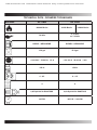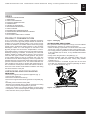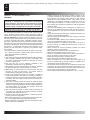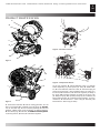
1
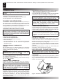
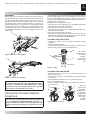
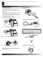
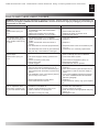
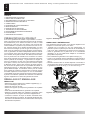
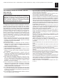
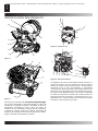
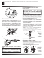
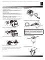
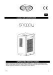
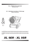
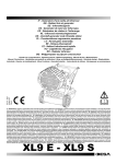
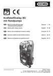
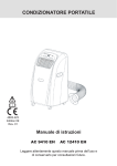
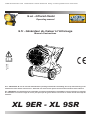
www.XL9Heater.com Distributor: North America Easy Clean Systems 916 638-0828
►en - Infrared Heater
Operating manual
►fr - Générateur de chaleur à l’infrarouge
Edition 12
4117.410
Manuel d’instructions
►en - IMPORTANT: Be sure to read and understand this operating manual before assembling, the set up and functioning or the
maintenance of this heater. The misuse of this heater can cause serious injuries. Conserve this manual for future reference.
►fr - IMPORTANT: Lire attentivement et comprendre ce manuel avant d’effecteur l’assemblage, la mise en marche ou l’entretien
du réchauffeur. Le mauvais usage de celui-ci peut provoquer de graves lésions. Conserver ce manuel comme futur objet de
référence.
XL 9ER - XL 9SR
www.XL9Heater.com Distributor: North America Easy Clean Systems 916 638-0828
TECHNICAL DATA - DONNÉES TECHNIQUES
MODEL
XL 9ER
146900 Btu/hr
XL 9SR
99300 Btu/hr
146900 Btu/hr
7.4 lb/hr
P1: 5 lb/hr
P2: 7.4 lb/hr
DIESEL / KEROSENE
DIESEL / KEROSENE
15.8 gal
15.8 gal
~110-120 V 50-60 Hz 1.2 A
~110-120 V 50-60 Hz 1.4 A
152 lb
152 lb
4 - 4.5
4 - 4.5
4
4
0,85 GpH 60°Hr DANFOSS
0,60 GpH 60°Hr DANFOSS
145 PSI
145 PSI / 260 PSI
www.XL9Heater.com Distributor: North America Easy Clean Systems 916 638-0828
1
en
INDEX
1. PRODUCT PRESENTATION
1. UNPACKING
2. SAFETY INFORMATION
3. PRODUCT IDENTIFICATION
4. COMBUSTIBLE
4. THEORY OF OPERATION
4. OPERATING INSTRUCTION
4. SAFETY DEVICE
4. MOVING AND TRANSPORTATION
5. PREVENTATIVE MAINTENANCE SCHEDULE
6. ACCESSORIES
7. FAULTS AND THEIR LIKELY CAUSES
PRODUCT PRESENTATION
XL 9 is a generator of heat by radiation. Radiation technology
is based on the same physical principle behind the warmth of
sunlight. The sun heats bodies without a flow of warm air but
by waves of radiation. The radiation method is becoming highly
popular among professional clients because of the countless
advantages it offers. XL 9 was designed on the basis of this
physical principle and has become irreplaceable in environments which require a constant, even source of heat for warmth,
defrosting and drying. In addition, its extremely low noise level
makes it suitable for working without having to put up with the
noise that other types of heater normally produce. The generator has rubber wheels for ease of movement and it can also
be raised and set at different heights by means of eyebolts. Its
extended autonomy and automatic thermostat function grant the
operator maximum freedom of use. The external fuel-tank indicator provides an easy check on whether fuel needs topping up.
The S model has a dual power device that enables a more efficient use of the machine under different conditions and during
the various seasons of the year.
Figur 1 - Packaging
ON PACKAGING AND STORING
If the generator needs to be placed in storage, or if it has suffered
major damage in transport, or needs to be repaired:
• Check for damage, in particular of a nature which could cause
loss of fuel. In this case, empty the tank of the remaining fuel.
• For storage, place the generator on the same pallet from which
it was unpacked and, for return, on any suitable EPA-branded
euro-pallet.
• Firmly anchor the generator to the pallet (Fig. 2).
•
Whenever possible, slide the cardboard packing from the
top down over the pallet and anchor it firmly using suitable
materials (Fig. 1).
• Store the machine in a suitable, dry place and do not stack
more than two. Despatch the generator preferably as shown
Fig. 1 or at least as shown in Fig. 2.
UNPACKING AND PACKAGING
UNPACKING
• Remove the supports used to pack the appliance (Fig. 1).
• Open top side of the box.
• Remove the cardboard from the top.
• Remove the supports that hold the generator to the pallet (Fig.
2).
• Delicately lower the heater off the pallet.
• Dispose of the material used to pack the generator according
to the current government regulations in your area.
• Check the machine for eventual damages incurred during
transportation, if the machine appears damaged immediately
inform the store where you purchased it.
Figur 2 - On pallett
www.XL9Heater.com Distributor: North America Easy Clean Systems 916 638-0828
2
en
SAFETY INFORMATION
WARNING
IMPORTANT: Read this entire manual carefully before
operating or effectuating any maintenance procedures
on this generator. The misuse of the generator can cause
serious of fatal injuries due to burns, fires, explosions,
electrical shock or asphyxiation from carbon monoxide.
DANGER: Carbon monoxide asphyxiation can be fatal.
Carbon Monoxide Asphyxiation - The first symptoms of carbon monoxide asphyxiation are similar to that of the flu, headaches, dizziness and/or nausea. These symptoms could be
caused by the malfunctioning of the generator. In this case go
outside immediately. Have the generator repaired. Then you
may start it again. Some people are more affected by the effects
of carbon monoxide than others, especially pregnant women,
those who suffer from heart or lung disease or anaemic people;
also those who have consumed alcoholic beverages, and those
who are at high altitudes. Be sure to read and understand all of
the warnings. Conserve this manual for future reference: it will
provide you with instructions to operate your generator safely
and correctly.
• Use only kerosene or diesel to diminish the risk of fire or explosion. Never use gasoline, naphtha, paint thinners, alcohol or
other highly flammable combustants.
• Filling the tank:
a) The personnel charged with filling the tank should be qualified
and completely familiar with the factory instructions and
the current governmental regulations regarding the secure
provision of generators.
b) Use only the type of fuel expressly specified on the
identification plate located on the generator.
c) B
efore filling the tank, extinguish all of the flames, including
the pilot light and wait for the generator to cool down.
d) While filling the tank inspect all of the fuel lines and their
junctions to check for fuel losses. Any losses must be
repaired before starting the generator again.
e) Under no circumstances should you conserve a quantity of
combustible superior to that which is necessary to maintain in
function the heater for one day in the same building or nearby
the heater. The fuel storage cisterns should be located in a
separate building.
f) All of the fuel tanks should be located a minimum safety
distance from the heater, (like current government regulation),
as well as oxyhydrogen blowpipe/ torches, welding equipment
and similar ignition sources (with the exception of the fuel
tank incorporated in the generator).
g) The fuel should be stored in areas where the flooring will
not soak up any fuel spills or any drips of fuel line, the flame
underneath that could cause a fire.
h) All fuel storage must be effectuated in compliance with the
current government regulations.
• Never use the generator in rooms where gasoline, paint thinner, or other highly flammable materials are located.
• While the heater is in use follow all of the local ordinances and
current government regulations.
• Heaters used close to large pieces of fabric, curtains or other similar materials must be situated at a safe distance from
these objects. The minimum safety distance is that which is
advised by the current regulations in the your country. It is also
advisable to use fireproof materials for coverings. Such materials should be fastened in a safe manner, so as to avoid
their catching fire and prevent interference with the generator
caused by wind.
• Use only well ventilated areas. Predispose an opening or at
least an air exchange system that meets the current governmental regulations in your area so that fresh air will be provided.
• Supply the generator with the proper voltage and frequency as
specified on the identification plate.
• Use only extension cords with three wires correctly connected
to a grounded plug.
• The minimum safety distance is the distance required by the
current governmental regulations in your area.
• Place the generator in a position so that when it is hot or in
function it will be on a stable and level surface, so that you
avoid starting a fire
• When you move or store the generator, maintain it in a level
position in order to avoid fuel loss.
• Keep children and animals away from the generator.
• Disconnect the generator when it is not in use.
• When it is controlled by another device (like a thermostat or a
timer), the heater could turn itself on at any time.
• Never place the generator in inhabited rooms.
• Never obstruct the aspiration or dissipation vents.
• When the heater is hot, connected to the power supply or in
function it should never be moved, handled, or refilled and no
maintenance should be performed on it.
• Smoke that is produced from the first combustion is due to the
evaporation of organic materials (ceramic) present in the combustion tank and anticorrosion oil present on the surface of the
burner. After a few minutes the smoke will stop.
• The environmental operating temperature is -22°F / +104°F.
www.XL9Heater.com Distributor: North America Easy Clean Systems 916 638-0828
3
en
PRODUCT IDENTIFICATION
A.
B.
A.
B.
H.
C.
I.
C.
D.
G.
D.
E.
F.
Figur 5 - Function controls
E.
S.
F.
R.
H.
T.
G.
Figur 3
R.
Q.
Q.
U1.
U1.
U2.
N2.
P.
P.
O.
I.
D.
L.
M. N1. O1.
N2.
O2.
Figur 6 - Components burner
N.
L.
M.
Figur 4
A. Combustion chamber, B. Hole for raising generator, C. Fuel
filter or pre-heated filter (optional), D. Fuel supply, E. Fuel
��������
Return, F. Fuel tank cap, G. Foot or wheel (optional), H. Fuel level
indicator, I. Block of the group combustion, L. Radiant deflector,
M. Fuel drain plug, N. Fuel tank, O. Handle
��������������������������
to move the generator, P. Hinge block, Q. Burner, R. Inclination regulator
A. Air vent regulator, B. Lighted ON/OFF button, C. ON/OFF
switch depending on power option (XL 9SR), D. RESET Button, E. Power indicator, F. Burner coffer, G. Thermostat plug, H.
Screw for burner block, I. Post-ventilation device, L. Flame control device, M. Transformer, N1. Pressure regulator (XL 9ER) of
the pump, N2. Pressure regulator (XL 9SR) of the pump, O1.
(XL 9ER) fuel pump, O2. (XL 9SR) fuel pump, P. Condenser, Q.
Motor, R. Burner tube, S. Combustion head regulator , T. Photoresistance, U1. Electrovalve 1° flame step (XL 9ER-SR), U2.
Electrovalve 2° flame step (XL 9SR)
www.XL9Heater.com Distributor: North America Easy Clean Systems 916 638-0828
4
en
COMBUSTIBLE
WARNING: The generator runs ONLY on kerosene or diesel fuel.
The use of impure combustible can cause:
• Blockage of the combustible filter and nozzle.
• Formation of carbonaceous deposits on the electrodes.
At low temperatures use non-toxic antifreeze.
THEORY OF OPERATION
The ventilation needed for proper combustion is produced by a
fan inside the burner. The air exits the burner sleeve and mixes
with the fuel which is nebulised by a high-pressure nozzle. The
fuel is aspirated from the fuel tank by a rotary pump which forces
it at high pressure up to the nozzle for nebulisation.
OPERATING INSTRUCTIONS
WARNING: Before putting the generator in function, and
therefore before connecting it to the electrical system,
you must check to see if the electrical systems technical
characteristics correspond to those on the identification
plate of the generator.
STARTING THE GENERATOR
1. Follow all of the safety information.
2. Fill the tank with diesel fuel or kerosene.
3. Close the fuel cap.
4. Plug the alimentation cord into a grounded wall plug with
the same tension as the one written on the generator’s
identification plate.
STARTING WITHOUT A THERMOSTAT
• XL 9ER
Set the switch (B Fig. 5) to the ON position (I). It begins the
period of pre-ventilation and after approximately 10 seconds
ones the combustion has beginning.
• XL 9SR
WARNING: Before starting the generator to make sure
that the button (C Fig. 5) is in position .
Set the switch (B Fig. 5) to the ON position (I). It begins the period of pre-ventilation and after approximately 10 second ones
the combustion has beginning.
For having the maximum potentiality portare set the switch (C
Fig. 5) to the
position.
If the machine isn’t working you should first control the following:
1. Make sure that the fuel tank (N Fig. 4) still contains fuel.
2. Press the Restart button (D Fig. 5 and 6).
If the generator still isn’t functioning consult the “FAULTS AND
THEIR LIKELY CAUSES” paragraph to identify the cause.
WARNING: Before the second ignition (machine extinguished and adequately cold) to assure the blocking of
the screws that block the anterior deflector (L Fig. 4).
WARNING: The electric power that feeds the generator
must be grounded and have a differential magneticthermal switch. The generator’s electric cord must be
attached to a plug equipped with a section switch.
TURNING THE GENERATOR OFF
Turn the switch (B Fig. 5) to the OFF position (O) or turn the thermostat or control device (Timer) off if there is one connected.
The flame will go out and the ventilation will continue until it has
finished its post-ventilation cycle (cooling down).
WARNING: Before unplugging the alimentation cord from
the wall, wait until the post-ventilation cycle is completely finished (it will take approximately 3 minutes to cool
down).
SAFETY DEVICE
The generator is equipped with a safety device (L Fig. 6), which
controls the flame. If one or more anomalies occur when the
generator is functioning, the device will block the burner and the
RESET button (D Fig. 5 or 6) will light up.
The generator also has a post-ventilation device which enables
optimal, automatic cooling of the combustion chamber for some
3 minutes.
Before turning the generator on again you must identify and
eliminate the cause that blocked the machine.
MOVING AND TRANSPORTATION
NOTICE: Before raising or moving the machine ensure
that the fuel tank caps (F and H Fig. 3) are firmly closed.
TRANSPORT
The generator is easy to move and it may be fixed in a raised
position thanks to its special eye-bolt mechanism (B Fig. 3 or
Fig. 7). This enables it to be set in the most suitable position for
heating, defrosting and drying.
STARTING WITH A THERMOSTAT
Regulate the thermostat or the control device (for example a
timer), if connected, so that it will allow the generator to function.
WARNING: The generator can ONLY function automatically
when the control device, for example a Thermostat or
a Timer, is connected to the generator. To connect the
control device to the machine consult the paragraph
entitled “ELECTRIC DIAGRAM”.
Before starting the machine or after the fuel line has been
completely emptied, the fuel flow to the nozzle should be
insufficient to cause the intervention of the security device which
controls the flame (see the “SAFETY DEVICE” paragraph)
that stops the generator. In this case, after having waited
approximately one minute, push the Reset button (D Fig. 5 and
6) and start the machine.
Figur 7 - Hooks in order to raise
www.XL9Heater.com Distributor: North America Easy Clean Systems 916 638-0828
MOVEMENT
Before picking up or moving the machine you must check to insure that the tank caps (G Fig. 3) are tightly shut. The generator
may be supplied with a rotating wheel. In this case, if the flooring allows it you may push the generator like a cart. In the case
the machine does not have rotating wheels it is necessary to
unblock the hinge (P Fig. 4) located on one of the lateral struts of
the generator. Lower the handle from its “resting position” (Fig.
8) Turn the handle to the “Transportation Position” (Fig. 9). Lift
the generator and position it so that it is resting on the two anterior wheels.
5
en
The instructions in this paragraph regarding the time between
service checks depend a lot on the cleanliness of the fuel and
the type of environment the generator is used in - the times given are for well-ventilated environments with little dust and considering the use of clean fuel.
Every 50 hours of operation you must:
• Dismantle the on-line cartridge (see “CLEANING THE FUEL
FILTER”) extract and clean the cartridge.
Every 200 hours of operation you must:
• Dismantle the pump filter (see “CLEANING THE PUMP FILTER) extract and clean it.
Every 300 hours of operation you must:
• Dismantle the burner and clean inside the burner’s tube, the
flame disk and the electrodes regulating, if necessary the distance (see “CLEANING OF THE BURNER”).
CLEANING THE FUEL FILTER
• Unscrew the plastic cup and extract the filtering element
(cartridge).
• Clean it well with kerosene.
• Insert the filter element back into its place and screw the cup
back into the main body of the combustion filter.
D.
Figur 8 - Position close handles
A.
C.
A. O-rings,
B. Plastic cup,
C. Filtering
element,
D. Body of
IN/OUT of the
fuel
B.
Figur 10 - Filter
CLEANING THE PUMP FILTER
Figur 9 - Position open handles
WARNING: Before moving the machine you must: turn
the machine off by following the indications provided in
paragraph “TURNING OFF THE GENERATOR”; unplug
the electrical source by pulling the plug out of the wall
and waiting for the generator to cool down.
PREVENTATIVE MAINTENANCE
SCHEDULE
WARNING: Before beginning any maintenance operation
you must: turn off the machine following the instructions
in the “TURNING OFF THE GENERATOR” paragraph; unplug the electrical alimentation by unplugging the cord
from the wall plug and waiting for the generator to cool
down.
• Dismantle the burner coffer (F. Fig. 5), to identify the pump of
the burner (O Fig. 6).
• Unscrew the nut (A Fig. 11) that blocking the filtering element
to the pump.
• Extract the filtering element (C Fig. 11) outside its place.
• Clean it well with kerosene.
• Insert the filtering element back into its place and screw the
nut to the pump.
A.
A. Nut for
A.
C.
blocking the
C.
B.
pump filter,
B.
B.
Single
elecD.
D.
trovalve for
XL 9ER doble
electrovalve
for XL 9SR,
C. Filter,
D. Pump
Figur 11 - Pomp of burner
www.XL9Heater.com Distributor: North America Easy Clean Systems 916 638-0828
6
en
CLEANING THE BURNER
• Remove the screw (H Fig. 5) that blocks the burner (A Fig. 3)
in the combustion chamber.
• Extract the burner from the combustion chamber (Fig. 3).
• Remove the three screws (B Fig. 12) that hold the burner tube
(A Fig. 12).
• Dismantle the tube.
• Remove the screw (C Fig. 13) that holds the group diskflameelectrodes and pull out the nozzle holder (F Fig. 14).
• Clean the flame disk (D Fig. 14) and the electrodes (E Fig. 14).
• Unscrew the nozzle (G Fig. 14) from the nozzle holder (F Fig.
14) clean it and if necessary replace it.
• Mount the nozzle (G Fig. 14) in its holder.
• Remount the group diskflame-electrodes placing it at a correct
distance as the illustration (Fig. 14) shows.
ACCESSORIES
THERMOSTAT
CONNECTING THE CONTROL DEVICE
A.
B.
C.
Figur 12 - Disassembly shell-burner
WARNING: Before beginning any maintenance operation
you must: stop the machine according to the instructions
provided in the paragraph “TURNING OFF THE GENERATOR”; disinsert the electrical supply by unplugging it and
waiting for the generator to cool down.
PRE-HEATING FILTER
C.
Figur 13 - Disassembly group diskflame-electrodes
4 mm
22 mm
D.
6-7 mm
E.
G.
4 mm
F.
H.
Figur 14 - Distances electrodes nozzle
A. Burner tube, B. Screw of the burner tube, C. Screw of the
group diskflame-electrodes, D. Flame disk, E. Electrodes, F.
Tube, G. Nozzle, H. Screw
ROTATING WHEEL WITH BRAKES
www.XL9Heater.com Distributor: North America Easy Clean Systems 916 638-0828
7
en
FAULTS AND THEIR LIKELY CAUSES
WARNING: Before beginning any maintenance operation you must: stop the machine according to the instructions provided in the paragraph “TURNING OFF THE GENERATOR”; disinsert the electrical supply by unplugging it and waiting for
the generator to cool down.
SYMPTOMS
POSSIBLE CAUSE
SOLUTION
The machine stops with
flame.
RESET button (D Fig. 5 o
6) on
1. Photo-resistance circuit is broken or the Photo-resistance is dirty with smoke residue
2. Dirty fuel filter
3. Flame Control device Circuit is broken
4. Flame disk or tube (Fig. 12, 13, 14) dirty
1. Clean or replace the Photo-resistance
The machine stops, spraying fuel without verifying the
flame. RESET button (D Fig.
5 o 6) on
1. The electrical system is not compatible
2. Ignition Transformer (M Fig. 6) disconnected or
broken
3. Ignition Transformer wires short circuit to
ground
4. The electrodes are not at the proper distance
1. Verify the entire circuit
2. Replace it
5. The electrodes short circuit to ground because
they are dirty or the insulation is damaged
The machine doesn’t spray
fuel and stops.
RESET button (D Fig. 5 o
6) on
1. Photo-electric cell sees a strong source of light
The burner doesn’t start
1. The control device (Thermostat or Timer) is on
2. Short circuit in Photo-resistance (T Fig. 6)
3. Power loss due to: disconnected switch (4) or
disconnected main switch due to power loss in
the line
4. The installation of the control device (Thermostat or Timer) is not correct
2. The power supply is missing a phase to the
motor
3. Fuel is not arriving to the pump
4. No fuel in the tank
5. Nozzle clogged
5. Break inside the flame control device
6. Fuse inside the burner bonnet
Flame is not well confirmed
with an unpleasant odour,
black smoke or flames coming out of the anterior deflector
1. Low pulverisation pressure
2. Insufficient combustible air
3. Nozzle clogged because it is dirty or old
4. Water in the fuel. Poor quality fuel
5. The tank is running out of fuel
2. Remove filter and clean it
3. Replace the flame control the circuit
4. Dismantle and clean it
3. Replace it
4. Reposition them at the correct distance (see
Fig. 14)
5. Clean them or, if necessary replace them
1. P
lace the machine so that the light source
does not directly face the front deflector
2. Control the electric system
3. Control the fuel supply lines (D Fig. 3)
4. Resupply the fuel tank
5. Dismantle and clean or replace it
1. Raise the value or control the Timer settings
2. Replace it
3. Turn off the electric system and then turn off
the switches or wait for the power supply to
return
4. C
ontrol the installation following the description in the “CONNECTING THE CONTROL
DEVICE” paragraph
5. Replace it
6. O
pen the burner coffer (F Fig. 5) and replace
it
1. Reestablish the correct value
2. Increase the combustible air
3. Clean or replace the nozzle
4. D
rain the fuel from the appropriate drain plug
(M Fig. 4)
5. Resupply the tank
www.XL9Heater.com Distributor: North America Easy Clean Systems 916 638-0828
10
1
fr
INDEX
1. PRÉSENTATION DU PRODUIT
1. DÉBALLAGE ET EMBALLAGE
2. INFORMATIONS AU SUJET DE LA SÉCURITÉ
3. IDENTIFICATION DES PRODUITS
4. COMBUSTIBLE
4. PRINCIPES DE FONCTIONNEMENT
4. MISE EN MARCHE
4. DISPOSITIFS DE SÉCURITÉ 4. TRANSPORT ET DÉPLACEMENT
5. PROGRAMME D’ENTRETIEN PRÉVENTIF
6. ACCESSOIRES
7. REPÉRAGE DES PANNES
PRÉSENTATION DU PRODUIT
XL 9 est un générateur de chaleur à rayonnement. La technologie à rayonnement suit le principe physique qui est à la base
du réchauffement par la lumière du soleil. En effet, le soleil
réchauffe les corps sans flux d’air chaud, mais à travers des
ondes irradiantes. Le système à rayonnement rencontre un succès croissant auprès de la clientèle professionnelle, en vertu
des nombreux avantages qu’offre ce type de technologie. XL 9
a été conçu sur la base de ce principe physique et il est ainsi devenu un générateur de chaleur indispensable dans les endroits
où l’on a besoin d’une source de chaleur homogène et uniforme
pour chauffer, décongeler et sécher. Par ailleurs, il est très silencieux et permet donc de travailler avec la machine en marche
sans devoir supporter les inconvénients causés par le bruit des
autres systèmes de chauffage. Le générateur est équipé de
roues en caoutchouc et peut donc être facilement transporté
d’une pièce à l’autre, tout comme il peut être soulevé et placé
à différents niveaux, grâce à des anneaux de fixage spéciaux.
Son autonomie de performance et la possibilité de l’utiliser en
automatique grâce à un thermostat offrent à l’opérateur une
grande liberté d’emploi. Un indicateur externe pour le contrôle
de la quantité de carburant contenue dans le réservoir permet
de vérifier rapidement s’il faut rajouter ou non du combustible.
La possibilité d’avoir deux degrés de puissance dans la version
S permet une utilisation optimale de la machine sous différents
régimes d’application et à toutes les périodes de l’année.
Figure 1 - Emballage
EMBALLAGE Y ENTREPOSAGE
Si le générateur doit être stocké, s’il a subi des dégâts lors du
transport ou s’il doit être réparé, vous devez:
• Contrôler que la machine ne soit pas endommagée, en
particulier qu’elle ne présente pas de fuite de combustible. Si
c’est le cas, vider complètement le réservoir de son carburant.
• Placer le générateur sur la plate-forme où il a été déballé
(stockage) ou sur une plate-forme adaptée à sa restitution
(europallet marqué EPA).
• Fixer solidement le générateur sur la plate-forme (Fig. 2).
• Lorsque c’est possible, placer l’emballage en carton depuis le
haut sur la plate-forme en le fixant avec des matériaux ad hoc
(Fig. 1).
• Stocker la machine dans un endroit adapté et non humide, et
ne pas placer plus de deux machines l’une sur l’autre. Expédier
le générateur comme sur la Fig. 1, ou du moins la Fig. 2.
DÉBALLAGE ET EMBALLAGE
DÉBALLAGE
• Éliminer les supports utiliser pour emballer l’appareil (Fig. 1).
• Ouvrir l’emballage à partir du haut.
• Enlever le carton par le haut.
• Enlever les supports qui bloquent le générateur sur la palette
(Fig. 2).
• Faire descendre délicatement le générateur de la palette.
• Éliminer le matériel utilisé pour emballer le générateur selon
les réglementations en vigueur dans l’État d’appartenance.
• Contrôler la machine de façon à déceler d’éventuels dommages subis durant le transport. Si l’appareil semble être abîmé, informer immédiatement le concessionnaire chez lequel a
été effectuée l’acquisition.
Figure 2 - Sur le palette
www.XL9Heater.com Distributor: North America Easy Clean Systems 916 638-0828
INFORMATIONS AU SUJET DE LA
SÉCURITÉ
AVERTISSEMENT
IMPORTANT: Lire attentivement et complètement le
manuel d’instructions avant d’allumer ou d’entretenir le
générateur. Un mauvais usage du générateur peut provoquer des lésions graves ou fatales à la suite de brûlures, d’incendie, d’explosion, de décharges électriques
ou d’asphyxie par hydroxyde de carbone.
DANGER: L’asphyxie par oxyde de carbone peut être fatale.
Asphyxie par oxyde de carbone - Les premiers symptômes
de l’asphyxie par oxyde de carbone ressemblent à ceux de la
grippe avec des maux de tête, des vertiges et/ou des nausées.
De tels symptômes pourraient être causés pas un fonctionnement défectueux du générateur. Dans ce cas, sortir immédiatement à l’air libre. Faire réparer le générateur. Certaines personnes ressentent davantage les effets de l’oxyde de carbone:
les femmes enceintes, ceux qui souffrent de maladies cardiaques ou pulmonaires, les anémiques, les alcooliques et ceux
qui se trouvent en altitude. S’assurer de lire et de comprendre
tous les avertissements. Conserver ce manuel comme future
référence: il fait en effet office de guide pour le fonctionnement
sûr et correct du générateur.
• Utiliser uniquement du kérosène ou du gas-oil afin d’éviter les
risques d’incendie ou d’explosion. Ne jamais utiliser d’essence,
de mazout, de solvants pour peintures, d’alcool ou d’autres
combustibles hautement inflammables.
• Réapprovisionnement:
a) Le personnel chargé du ravitaillement doit être qualifié et
familiarisé avec les instructions du fabricant et avec la réglementation en vigueur relative au réapprovisionnement en
toute sécurité des générateurs.
b) Utiliser uniquement le combustible expressément indiqué sur
l’étiquette d’identification du générateur.
c) Avant d’effecteur le réapprovisionnement, éteindre tous les
flammes, y compris celle de veille, et attendre que le générateur refroidisse.
d) Au cours du réapprovisionnement, inspecter toutes les
conduits du combustible et les raccordements à la recherche
d’éventuelles fuites. Toute fuite doit être réparée avant de
remettre en marche le générateur.
e) Une quantité de combustible supérieure à celle pour maintenir en fonction le générateur pendant une journée ne doit
en aucun cas être dans le même bâtiment et à proximité du
générateur. Les citernes de stockage du carburant doivent
être dans une structure séparée.
f) Tous les réservoirs du combustible doivent se trouver à une
distance minimum de sécurité des réchauffeurs, chalumeaux
oxhydriques, équipements pour la soudure et d’autres
sources inflammables (exception faite du réservoir de combustible incorporé dans le générateur).
g) Le combustible doit être conservé dans des locaux dont le sol
ne permet pas la pénétration et l’égouttement du combustible
lui-même sur des flammes sous-jacentes qui peuvent provoquer le départ d’un feu.
h) La conservation du combustible doit être réalisée conformément à la réglementation en vigueur.
11
2
fr
• Ne jamais utiliser le générateur dans des locaux où sont présents de l’essence, des solvants pour peintures ou d’autres
vapeurs hautement inflammables.
• Pendant l’utilisation du générateur, respecter toutes les ordonnances locales et les réglementations en vigueur.
• Les réchauffeurs utilisés à proximité de bâches, de tentures ou
d’autres matériels de couverture de même type doivent être
situés à une distance de sécurité de ces derniers. La distance
minimum de sécurité est celle recommandée par les réglementations en vigueur dans l’État d’appartenance. Il est également
conseillé d’avoir recours à des équipements de couverture ignifugés. De tels matériels doivent être fixés de façon sûre pour
éviter qu’ils ne prennent feu et qu’il y ait des interférences avec
le générateur à cause du vent.
• Utiliser seulement dans des espaces bien aérés. Prévoir une
ouverture ou au moins un échange d’air adéquat selon les réglementations en vigueur dans l’État d’appartenance de façon
à faire pénétrer de l’air frais depuis l’extérieur.
• Alimenter le générateur seulement avec un courant ayant la
tension et la fréquence indiquées sur l’étiquette d’identification.
• Utiliser uniquement des rallonges à trois fils, opportunément
reliées à la masse.
• Distance minimum de sécurité entre le réchauffeur et des
substances combustibles selon les réglementations en vigueur
dans l’État d’appartenance.
• Mettre le générateur chaud ou en marche sur une surface
stable et plane de façon à éviter les risques d’incendie.
• Quand le générateur est déplacé ou simplement conservé,
le maintenir horizontal pour éviter que le combustible ne
s’échappe.
• Mettre le générateur hors de portée des enfants et des animaux.
• Débrancher le générateur de la prise de courant quand il est
éteint.
• Quand le réchauffeur est muni d’un dispositif de contrôle (thermostat ou minuterie), il peut s’allumer à tout moment.
• Ne jamais utiliser le générateur dans des pièces fréquemment
habitées.
• Ne jamais boucher la grille d’aspiration et de dissipation.
• Quand le réchauffeur est chaud, relié au courant ou en marche,
il ne doit jamais être déplacé, manipulé, ravitaillé ou encore
sujet à une quelconque intervention d’entretien.
• La fumée qui s’échappe lors de la première combustion est
due à l’évaporation de matières organiques (céramiques) présentes dans la chambre de combustion et à l’huile anticorrosion présente à la surface des composants du brûleur. Après
quelques minutes, la fumée disparaîtra.
• Utiliser la machine à une température comprise entre -30°C
et +40°C.
www.XL9Heater.com Distributor: North America Easy Clean Systems 916 638-0828
12
3
fr
IDENTIFICATION DES PRODUITS
A.
B.
A.
B.
H.
C.
G.
I.
C.
D.
E.
D.
Figure 5 - Fonctions du
E.
F.
S.
R.
F.
Figure 3
T.
H.
G.
R.
Q.
U1.
Q.
U1.
U2.
N2.
P.
P.
I.
D.
L.
M. N1. O1.
O.
Figure 6 - Pièces du brûleur
N.
L.
Figure 4
M.
A. Chambre de combustion, B. ���������������������������������
Trou pour le transport de l’appareil, C. Filtre combustible ou filtre préchauffage (en option), D.
Refoulement combustible, E. Retour combustible, F. Bouchon
ravitaillement combustible, G. Pied ou Roue (en option), H.
Indicateur niveau combustible, I. Blocage groupe combustion,
L. Déflecteur antérieur, M. Bouchon vidange combustible, N.
Réservoir, O. Poignée pour le transport du générateur., P. Blocpoignée, Q. Brûleur, R. Régulateur inclinaison
N2.
O2.
A. Régulation volet d’air, B. Interrupteur ON/OFF lumineux, C.
Interrupteur ON/OFF seconde puissance (XL 9SR), D. Bouton
RESET, E. Voyant tension, F. Coffre brûleur, G. Branchement
thermostat, H. Vis, I. Fiche post-ventilation, L. Appareillage
contrôle flamme, M. Transformateur, N1. Réglage Pression (XL
9ER) de la pompe, N2. Réglage Pression (XL 9SR) de la pompe,
O1. Pompe à combustible (XL 9ER), O2. Pompe à combustible
(XL 9SR), P. Condensateur, Q. Moteur, R. Conduit du brûleur, S.
Réglage de la tête de combustion, T. Photorésistance, U1. Soupape électrique 1° stade de flamme (XL 9ER-SR), U2. Soupape
électrique 2° stade de flamme (XL 9SR)
www.XL9Heater.com Distributor: North America Easy Clean Systems 916 638-0828
COMBUSTIBLE
AVERTISSEMENT: Le générateur fonctionne SEULEMENT
avec du kérosène ou du gas-oil.
L’usage d’un combustible impur peut causer:
• L’engorgement du filtre du combustible et de l’injecteur.
• La formation de dépôts carbonés sur les électrodes.
À basse température, utiliser des additifs antigel non toxiques.
PRINCIPES DE FONCTIONNEMENT
L’air assurant une combustion correcte est produit par la rotation
d’un ventilateur à l’intérieur du brûleur. Le flux de l’air sort par le
tube du brûleur et se mélange avec le combustible qui est pulvérisé par une buse à haute pression. Le combustible pulvérisé
par la buse est contrôlé par une pompe rotative qui l’aspire hors
du réservoir et le pousse à haute pression jusqu’à la buse pour
la pulvérisation.
MISE EN MARCHE
ATTENTION: Avant de mettre en marche le générateur
et donc avant de le relier au courant électrique
d’alimentation, il faut contrôler si les caractéristiques du
courant électrique correspondent à celles reportées sur
l’étiquette d’identification du générateur.
ALLUMAGE DU GÉNÉRATEUR
1. Suivre toutes les instructions relatives à la sécurité.
2. Effectuer le ravitaillement avec du gas-oil ou du kérosène.
3. Fermer le bouchon du réservoir
4. Insérer la fiche du câble d’alimentation dans une prise murale
reliée à la masse et ayant une tension égale à celle reportée
sur l’étiquette d’identification de l’appareil.
ALLUMAGE SANS THERMOSTAT
• XL 9ER
Mettre l’interrupteur (B Fig. 5) sur la position ON; la période de
pré-ventilation démarre environ 10 secondes après le début de
la combustion.
• XL 9SR
AVERTISSEMENT: Avant d’actionner le générateur, vérifiez que l’interrupteur (C Fig. 5) soit éteint (position ).
Allumez (pièce B Fig. 5) dans la position ON (I). La phase de
pré-ventilation démarre, et après 10 secondes environ la combustion commence aussi. Pour obtenir une potentialité maximale il faut allumer (C Fig. 5) - position
.
ALLUMAGE AVEC THERMOSTAT
Régler le thermostat ou le dispositif de contrôle (par exemple
une minuterie), si connecté, de façon à en permettre le fonctionnement.
ATTENTION: Le générateur peut fonctionner de façon
automatique SEULEMENT quand un dispositif de
contrôle, par exemple un thermostat ou une minuterie, est
connecté au générateur. Pour connecter le dispositif de
contrôle à l’appareil, consulter le paragraphe «SCHÉMA
ÉLECTRIQUE».
13
4
fr
Lors de la première mise en marche ou après la vidange complète du circuit du gas-oil, le flux de gas-oil au niveau de l’injecteur peut être insuffisant et causer l’intervention du dispositif de
sécurité de contrôle de la flamme (voir le paragraphe «DISPOSITIFS DE SÉCURITÉ») qui arrête le générateur. Dans ce cas,
après avoir attendu pendant environ une minute, appuyer sur le
bouton Reset (D Fig. 5-6) et allumer de nouveau l’appareil.
En cas de non-fonctionnement, les premières opérations à faire
sont les suivantes:
1. Contrôler que le réservoir (N Fig. 4) contient encore du gas-oil.
2. Appuyer sur le bouton RESET de pour réenclencher le dispositif (D Fig. 5-6).
Si le générateur ne fonctionne toujours pas après de telles opérations, consulter le paragraphe «REPÉRAGE DES PANNES»
et comprendre la cause du non fonctionnement.
AVERTISSEMENT: Avant le deuxième allumage (générateur éteint et froid), il faut vérifier le blocage des vis bloquant le déflecteur antérieur (L Fig. 4).
AVERTISSEMENT: La ligne électrique d’alimentation du
générateur doit être pourvue de mise à terre et d’un interrupteur magnéto-thermique différentiel. La fiche électrique du générateur doit être branchée à une prise munie
d’un interrupteur coupe courant.
EXTINCTION DU GÉNÉRATEUR
Mettre l’interrupteur (B Fig. 5) sur la position OFF ou agir, si
connecté, sur le thermostat ou sur le dispositif de contrôle (minuterie), en le réglant de façon adéquate. La flamme s’éteint et
la ventilation persiste jusqu’à l’achèvement du cycle de postventilation (refroidissement).
AVERTISSEMENT: Avant de débrancher le câble d’alimentation de la prise, attendre l’achèvement du cycle de postventilation (refroidissement d’environ 3 minutes).
DISPOSITIFS DE SÉCURITÉ
Le générateur est doté d’un système de sécurité (L Fig. 6) pour
le contrôle de la flamme. Si on constate une ou plusieurs anomalies au cour du fonctionnement, cet appareillage provoque le
blocage du brûleur et l’allumage du voyant du bouton RESET
(D Fig. 5 o 6). Le générateur est aussi muni d’un équipement
de post-ventilation. Cet équipement permet un refroidissement
optimal et automatique de la chambre de combustion pendant
une durée d’environ 3 min. Avant de remettre en marche le générateur, repérer et éliminer la cause qui a provoqué le blocage.
TRANSPORT ET DÉPLACEMENT
ATTENTION: Avant de soulever ou de déplacer la machine, s’assurer que les bouchons du réservoir (F et H
Fig. 3) soient bien fermés.
TRANSPORT
Le générateur peut être facilement transporté d’une pièce à
l’autre, tout comme il peut être soulevé et placé à différents niveaux, grâce à des anneaux de fixage spéciaux (B Fig. 3 ou Fig.
7). Il est donc possible de fixer la machine et de la soulever pour
la placer aux endroits où l’on doit chauffer, décongeler et sécher.
www.XL9Heater.com Distributor: North America Easy Clean Systems 916 638-0828
14
5
fr
PROGRAMME D’ENTRETIEN
PRÉVENTIF
Figure 7 - Crochets afin d’augmenter
DÉPLACEMENT
Le générateur peut être muni de roues pivotantes (G Fig. 3).
Dans ce cas, si le terrain le permet, il convient de pousser le
générateur comme un chariot. Au cas où l’appareil n’a pas de
roues pivotantes, il convient de bloquer le pivot (P Fig. 4) placé
sur un des montants latéraux du générateur. Baisser la poignée
de la «position au repos» (Fig. 8). Tourner la poignée à la position «position de déplacement» (Fig. 9). Soulever le générateur
et le déplacer en le faisant rouler sur les roues antérieures.
AVERTISSEMENT: Avant de commencer une quelconque
opération d’entretien, arrêter la machine selon les indications décrites dans le paragraphe «EXTINCTION DU
GÉNÉRATEUR», arrêter l’alimentation électrique en débranchant la fiche de la prise électrique et attendre que le
générateur refroidisse.
Les instructions contenues dans ce paragraphe, qui concernent
les temps d’entretien, sont étroitement liées au nettoyage du
combustible et au type d’espace dans lequel le générateur est
utilisé. En particulier, les indications ci-dessous sont valables
pour des espaces de travail aérés et peu poussiéreux, et lorsque
le combustible employé est propre.
Toutes les 50 heures de fonctionnement, il faut:
• Démonter la cartouche du filtre en ligne (voir «NETTOYAGE
FILTRE GAS-OIL»), la sortir et la nettoyer.
Toutes les 200 heures de fonctionnement, il faut:
• Démonter la cartouche du filtre en ligne (voir «NETTOYAGE
FILTRE DE LA POMPE»).
Toutes les 300 heures de fonctionnement, il faut:
• Démonter le brûleur et nettoyer à l’intérieur du conduit du brûleur le disque-flamme et les électrodes en réglant si nécessaire
la distance (voir «NETTOYAGE DE ROUTINE DU BRÛLEUR»).
NETTOYAGE FILTRE GAS-OIL
• Dévisser le verre en plastique et sortir l’élément filtrant (cartouche).
• Le nettoyer de façon adéquate avec le kérosène.
• Remettre l’élément filtrant à sa place et visser le verre en plastique au corps fixe du filtre combustible.
A. Garnitures,
B. Verre en
plastique,
C. Élément
filtrant,
D. Corps fixe
du filtre
combustible
D.
A.
C.
Figure 8 - Position avec poignées fermées (au repos)
B.
Figure 10 - Filtre en ligne
NETTOYAGE FILTRE DE LA POMPE
• Démonter le coffre du brûleur (F Fig. 5), identifier la pompe du
brûleur (O Fig. 6).
•D
évisser l’écrou (A Fig. 11) fixant l’élément filtrant à la pompe.
• Extrayez l’élément filtrant (C Fig. 11).
• Nettoyez-le bien avec du kérosène.
• Insérez l’élément filtrant et vissez l’écrou à la pompe.
Figure 9 - Position avec poignées ouvertes (en déplacement)
AVERTISSEMENT: Avant de déplacer l’appareil, il faut arrêter la machine selon les indications décrites dans le paragraphe «EXTINCTION DU GÉNÉRATEUR», débrancher
l’alimentation électrique en ôtant la fiche de la prise électrique murale et attendre que le générateur refroidisse.
A.
B.
A.
C.
B.
D.
Figure 11 - Pompe du brûleur
C.
A. Écrou,
B. Electrovannesiple pour
D. XL 9ER, electrovanne double
pour XL 9SR,
C. Filtrant,
D. Pompe
www.XL9Heater.com Distributor: North America Easy Clean Systems 916 638-0828
NETTOYAGE DE ROUTINE DU BRÛLEUR
• Dévisser la vis (H Fig. 5) qui bloque le brûleur (A Fig. 3) à la
chambre de combustion.
• Extraire le brûleur de la chambre de combustion (Fig. 3).
• Dévisser les trois vis (B Fig. 12) qui bloquent le conduit du
brûleur (A Fig. 12).
• Démonter le conduit.
• Dévisser la vis (C Fig. 13) qui bloque le groupe disque flammeélectrodes et l’enlever du porte-injecteur (F Fig. 14).
• Nettoyer le disque flamme (D Fig.14) et les électrodes (E Fig.
14).
• Dévisser l’injecteur (G Fig. 14) du porte-injecteur (F Fig. 14).
Le nettoyer ou, si nécessaire, le remplacer.
• Remonter l’injecteur (G Fig. 14) à sa place.
• Remonter le groupe disque flamme-électrodes en réglant les
distances de façon adéquate d’après l’illustration (Fig. 14).
15
6
fr
ACCESSOIRES
THERMOSTAT
CONNEXION DU DISPOSITIF DE CONTRÔLE
A.
B.
C.
Figure 12 - Coquille-brûleur de démontage
AVERTISSEMENT: Avant de commencer une quelconque
opération d’entretien, arrêter la machine selon les indications décrites dans le paragraphe «EXTINCTION DU
GÉNÉRATEUR», arrêter l’alimentation électrique en débranchant la fiche de la prise électrique et attendre que le
générateur refroidisse.
C.
FILTRE DE PRÉCHAUFFAGE
Figure 13 - Démontage du groupe disque flame-électrodes
4 mm
22 mm
D.
4 mm
6-7 mm
E.
G.
F.
H.
Figure 14 - Distances électrodes - injecteur
A. Conduit du brûleur, B. Vis qui bloquent le conduit du brûleur,
C. Vis qui bloque, D. Flame disk, E. Électrodes, F. Tube, G.
Nozzel, H. Vis
ROULETTE PIVOTANTE
www.XL9Heater.com Distributor: North America Easy Clean Systems 916 638-0828
16
7
fr
REPÉRAGE DES PANNES
AVERTISSEMENT: Avant de commencer une quelconque opération d’entretien, arrêter la machine selon les indications
décrites dans le paragraphe «EXTINCTION DU GÉNÉRATEUR», arrêter l’alimentation électrique en débranchant la fiche de
la prise électrique et attendre que le générateur refroidisse.
PANNE OBSERVÉE
CAUSE POSSIBLE
L’appareil se bloque avec
une flamme.
Bouton RESET (D Fig. 5 o 6)
allumé
1. Circuit de la Photo-résistance en panne ou
Photo-résistance encrassée de fumée
2. Filtre à combustible sale
3. Circuit de la carte de contrôle de la flamme en
panne
4. Disque flamme ou conduit (Fig. 12, 13, 14)
sales
SOLUTION
1. N
ettoyer la Photo-résistance ou la emplacer
2. Démonter le filtre et le nettoyer
3. D
émontez le déflecteur antérieur et nettoyez
l’intérieur de la chambre de combustion
4. Les démonter et les nettoyer
L’appareil se bloque et crache 1. Installation électrique non conforme
du combustible sans flamme. 2. Transformateur d’allumage �����������������
(M Fig. 6)�������
interBouton RESET (D Fig. 5 o 6)
rompu
allumé
3. Les câbles du transformateur d’allumage sont
à la masse
4. Les électrodes ne sont pas à la bonne distance
5. Les électrodes sont à la masse parce qu’elles
sont sales ou parce que l’isolant est abîmé
1. Vérifier tout le circuit
2. Le remplacer
L’appareil ne crache pas de
combustible et se bloque.
Bouton RESET (D Fig. 5 o 6)
allumé
1. P
lacez la machine en évitant la source de
lumière sur le déflecteur antérieur
2. Contrôler l’installation électrique
3. C
ontrôler les tubes d’arrivée du gas-oil (D
Fig. 3)
4. Effectuer le ravitaillement
5. Le nettoyer ou le remplacer
1. La photorésistance détecte une source de
lumière intense
2. Il manque une phase au Moteur
3. Le gas-oil n’arrive pas à la pompe
4. Il manque du gas-oil dans le réservoir
5. Injecteur bouché
Brûleur bloqué
1. Dispositif de contrôle (Thermostat ou Minuterie) ouvert
2. Photo-résistance (T Fig. 6) en court-circuit
3. La tension manque à cause de l’interrupteur
débranché, de l’interrupteur du compteur
ayant sauté ou d’un manque de tension dans
la ligne électrique
4. L’installation du dispositif de contrôle (Thermostat ou Minuterie) n’est pas correcte
5. Panne interne à l’appareillage de contrôle de
la flamme
6. Fusible brûlé à l’intérieur du coffre
Flamme faible avec une mauvaise odeur, une fumée noire
et des flammes qui sortent du
déflecteur antérieur
1. Basse pression de pulvérisation
2. Air pour la combustion insuffisant
3. Injecteur bouché car sale ou abîmé
4. Eau dans le combustible. Carburant de mauvaise qualité
5. Le combustible est en train de finir
3. Les remplacer
4. Les remettre dans la position recommandée
(Fig. 14)
5. Les nettoyer ou, si nécessaire, les remplacer
1. E
n augmenter la valeur ou contrôler les
temps de la Minuterie
2. La remplacer
3. F
ermer l’installation électrique et fermer successivement les interrupteurs ou attendre le
retour de la tension
4. C
ontrôler l’installation selon la description
du «CONNECTUNG DU THERMOSTAT
D’AMBIANCE»
5. La remplacer
6. O
uvrez le coffre du brûleur (F Fig. 5) et remplacez-le
1. La remettre à la valeur prévue
2. Augmenter l’air pour la combustion
3. Nettoyer l’injecteur ou le changer
4. V
idanger le combustible à partir du bouchon
prévu à cet effet (M Fig. 4)
5. Effectuer le ravitaillement en combustible
www.XL9Heater.com Distributor: North America Easy Clean Systems 916 638-0828
CE CONFORMITY CERTIFICATE - DICHIARAZIONE DI CONFORMITÀ CE - EG-KONFORMITÄTSERKLÄRUNG - DECLARACIÓN DE CONFORMIDAD CE - DECLARATION DE CONFORMITE
CE - EG-CONFORMITEITVERKLARING - DECLARAÇÃO DE CONFORMIDADE CE - EU-OVERENSSTEMMELSESERKLÆRING - EY-VAATIMUSTENMUKAISUUSVAKUUTUS - CE-SAMSVARSERKLÆRING - EG-FÖRSÄKRAN OM ÖVERENSSTÄMMELSE - DEKLARACJA ZGODNOŚCI WE
- ДЕКЛАРАЦИЯ О СООТВЕТСТВИИ СЕ - PROHLÁŠENÍ O SHODĚ CE - EK MEGFELELŐSÉGI
NYILATKOZAT - IZJAVA O SKLADNOSTI IN OZNAKA CE - CE UYGUNLUK BEYANI - IZJAVA CE
O SUKLADNOSTI - ES ATITIKTIES DEKLARACIJA - EK ATBILSTĪBAS - DEKLARĀCIJA - EÜ VASTAVUSDEKLARATSIOON - DECLARAŢIE DE CONFORMITATE CE - PREHLÁSENIE O ZHODE
CE - ДЕКЛАРАЦИЯ ЗА СЪВМЕСТИМОСТ СЕ - ДЕКЛАРАЦІЯ ВІДПОВІДНОСТІ CE - IZJAVA CE O
PRIKLADNOSTI ΔΗΛΩΣΗ ΣΥΜΜΟΡΦΩΣΗΣ CE - CE 符合性声明
MCS ITALY S.p.A. Via Tione, 12 - 37010 - Pastrengo (VR) ITALY
Product: - Prodotto: - Produkt: - Producto: - Produit: - Product: - Produto: - Produkt: - Tuote: - Produkt: - Produkt: - Produkt: - Изделие: - Výrobek: - Termék: - Izdelek: - Ürün: - Proizvod: - Gaminys: - Ierīce: - Toode: - Produsul: - Výrobok:
- Продукт: - Виріб: - Proizvod: - Προϊόν: - 产品:
XL 9ER - XL 9SR
We declare that it is compliant with: - Si dichiara che è conforme a: - Es wird als konform mit den folgenden Normen
erklärt: - Se declara que está en conformidad con: - Nous déclarons sa conformité à: - Hierbij wordt verklaard dat het
product conform is met: - Declara-se que está em conformidade com: - Vi erklærer at produktet er i overensstemmelse med: - Vakuutetaan olevan yhdenmukainen: - Man erklærer at apparatet er i overensstemmelse med: - Härmed
intygas det att produkten är förenlig med följande: - Oświadcza się, że jest zgodny z: - Заявляем о соответствии
требованиям: - Prohlašuje se, že je v souladu s: - Kijelentjük, hogy a termék megfelel az alábbiaknak: - Izpolnjuje
zahteve: - Aşağıdaki standartlara uygun olduğunu beyan ederiz: - Izjavljuje se da je u skladu s: - Pareiškiame, kad
atitinka: - Tiek deklarēts, ka atbilst: - Käesolevaga deklareeritakse, et toode vastab: - Declarăm că este conform
următoarelor: - Prehlasuje sa, že je v súlade s: - Декларира се че отговаря на: - Відповідає вимогам: - Izjavljuje se
da je u skladu s: - Δηλώνουμε ότι είναι σύμφωνο με: - 兹证明符合:
2004/108 EEC, 2006/95 EEC
EN 55014-1 (2006) + A1 (2009), EN 61000-3-2 (2006), EN 61000-3-3 (2008), EN 55014-2 (1997) + A1
(2001) + A2 (2008), EN 62233 (2008), EN 60335-2-102 (2006), EN 60335-1 (2002) + A11 (2004) + A1
(2004) + A12 (2006) + A2 (2006) + A1/EC (2007) + A13 (2008)
Pastrengo, 10/10/2012
Stefano Verani (CEO MCS Group)
www.XL9Heater.com Distributor: North America Easy Clean Systems 916 638-0828
MCS Italy S.p.A.
Via Tione, 12 - 37010
Pastrengo (VR) - Italy
[email protected]
MCS Central Europe Sp. z o.o
ul Magazynowa 5A, 62-023
Gadki, Poland
[email protected]
MCS China LTD
Unit 11, No. 198, Changjian Rd.,
Shanghai, China
[email protected]