1
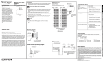
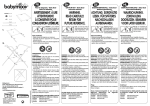
Eikon
Arké
Idea
Plana
20515
19515
16955
14515
Interfaccia per comandi tradizionali 230 V~, 12-24 V~ o
12‑24 V d.c. - 2 moduli.
Interface for traditional switches 230 V~, 12-24 V~ or
12-24 V d.c. - 2 modules.
Dispositivo per il collegamento di apparecchiature elettriche di tipo ON-OFF (esempio: anemometri, sensori pioggia, sensori umidità, ecc.) o tradizionali (interruttori,
pulsanti, ecc.) al sistema bus By-me.
Alimentazione dei contatti separata elettricamente dall’elettronica del dispositivo a
garanzia di immunità ai disturbi.
La chiusura dei contatti viene rilevata se rimangono chiusi per almeno 100 ms.
Non gestisce alcun scenario.
Device for connecting electrical equipment of the ON-OFF type (for example,
anemometers, rain sensors, humidity sensors, etc.) or conventional ones (switches,
push-buttons, etc.) to the By-me BUS system.
Contact power supply electrically separated from the device’s electronics to ensure
immunity from interference.
Contact closure is detected if they remain closed for at least 100 ms.
No scenarios are managed.
La lunghezza massima dei cavi per il collegamento dei contatti con l’interfaccia non deve superare i 100 m.
The maximum length of the cables for connecting the contacts to the interface must not exceed 100 m.
Nota: Nel caso in cui vengano utilizzati entrambi gli ingressi, la tensione dei contatti
ad essi collegati deve essere la stessa (230 V~, 12-24 V~ oppure 12-24 V d.c.).
CHARACTERISTICS.
CARATTERISTICHE.
•Tensione nominale di alimentazione: BUS 29 V
•Assorbimento: 10 mA
•Morsetti:
-bus TP
-ingressi per 2 contatti (230 V~, 12-24 V~, 12-24 V d.c.)
CONFIGURAZIONE.
PER LE OPERAZIONI DI INSTALLAZIONE E CONFIGURAZIONE, VEDERE IL
MANUALE ISTRUZIONI DEL SISTEMA By-me ALLEGATO ALLA CENTRALE
DI CONTROLLO.
•Blocchi funzionali:
-2 blocchi funzionali, ognuno associato a uno dei due contatti di ingresso
-ogni blocco funzionale può appartenere al massimo a 4 gruppi.
•Selezione del blocco funzionale (configurazione), quando la centrale, durante la
creazione dei gruppi, richiede di premere il pulsante dei dispositivi:
-premere una volta il pulsante di configurazione per selezionare il primo blocco
funzionale (lampeggio veloce per circa 3 s del led);
- premere due volte il pulsante di configurazione per selezionare il secondo blocco
funzionale (lampeggio lento per 3 s circa del led).
Al termine del lampeggio il led resta acceso fisso e il blocco funzionale viene
configurato dalla centrale. Al termine dell’operazione il led si spegne.
PARAMETRI.
Il funzionamento del dispositivo può essere impostato dalla centrale nelle modalità
indicate di seguito:
•Normale: invio di un messaggio di ON alla chiusura del contatto e di OFF all’apertura del contatto.
•Invertito: invio di un messaggio di OFF alla chiusura del contatto e di ON all’apertura del contatto.
•Toggle chiusura: invio alternato di un messaggio di ON o di OFF a ogni chiusura
del contatto.
•Toggle apertura: invio alternato di un messaggio di ON o di OFF a ogni apertura
del contatto.
•Possibilità di attivare o disattivare il led; quando attivo indica l’ultimo messaggio
inviato:
-led acceso se ultimo messaggio inviato ON
-led spento se ultimo messaggio inviato OFF (impostazione di default)
•Parametri di default:
-funzionamento: normale
-led: spento.
REGOLE DI INSTALLAZIONE.
L’installazione deve essere effettuata con l’osservanza delle disposizioni regolanti l’installazione del materiale elettrico in vigore nel paese dove i prodotti sono installati. Per
ulteriori istruzioni si faccia riferimento al manuale allegato alla centrale di controllo.
CONFORMITÀ NORMATIVA.
Direttiva BT
Direttiva EMC
Norma EN 50428.
Viale Vicenza, 14 - 36063 Marostica VI - Italy
Tel. +39 0424 488 600 - Fax (Italia) +39 0424 488 188
Fax (Export) +39 0424 488 709
www.vimar.com
•Rated supply voltage: BUS 29 V
•Input: 10 mA
•Terminals:
-TP bus
-inputs for 2 contacts (230 V~, 12-24 V~, 12-24 V d.c.)
CONFIGURATION.
FOR THE OPERATIONS OF INSTALLATION AND CONFIGURATION, SEE
THE By-me SYSTEM INSTRUCTIONS MANUAL ATTACHED TO THE
CONTROL UNIT.
•Functional blocks:
-2 functional blocks, each one associated with one of the two input contacts
-each functional block can belong to at most 4 different groups.
•Selecting the functional block (configuration), when the control unit, during group
creation, requires pressing the device button:
- press the configuration button once to select the first functional block (LED blinking fast for approximately 3 s);
-press the configuration button twice to select the second functional block (LED
blinking slowly for approximately 3 s).
After blinking, the LED will stay steady on red and the functional block will be
configured by the control unit. At the end of this operation the LED will go out.
PARAMETERS.
The operation of the device can be set by the control unit in the following manners:
•Normal: sending an ON message on closing the contact and OFF on opening the
contact.
•Reverse: sending an OFF message on closing the contact and ON on opening
the contact.
•Toggle closing: alternately sending an ON or OFF message each time the contact
is closed.
•Toggle opening: alternately sending an ON or OFF message each time the contact is opened.
•Possibility of turning the LED on or off; when it is on it indicates the last message
sent:
-LED on if last message sent ON
-LED off if last message sent OFF (default setting)
•Default parameters:
-operation: normal
-LED: off.
INSTALLATION RULES.
Installation should be carried out observing current installation regulations for
electrical systems in the country where the products are installed. For further
instructions,please see the manual attached to the control panel.
CONFORMITY.
LV directive
EMC directive
Standard EN 50428.
49400466B0 01 1406
VIMAR - Marostica - Italy
Eikon
Arké
Idea
Plana
20515
19515
16955
14515
Interface pour commandes traditionnelles 230 V~, 12-24 V~
ou 12-24 V c.c. - 2 modules.
Schnittstelle für herkömmliche Schalter, Spannungsversorgung
230 V~, 12-24 V~ oder 12-24 V d.c. - 2 Module.
Dispositif pour le raccordement des appareils électriques de type ON-OFF (exemple : anémomètres, capteurs pluie, capteurs humidité etc.) ou traditionnels (interrupteurs, boutons etc.) au système bus By-me.
Alimentation des contacts séparée électriquement de l’électronique du dispositif en
garantie d’immunité contre les perturbations.
La fermeture des contacts est relevée s’ils restent fermés pendant au moins 100 ms.
Ne gère aucune scénario.
Vorrichtung für den Anschluss von elektrischen Apparaten des Typs ON-OFF
(Beispiel: Anemometer, Niederschlagsensoren, Feuchtigkeitssensoren usw.) oder
herkömmlichen Apparaten (Schalter, Tasten usw.) an das By-me-BUS-System.
Zur Gewährleistung der Immunität gegen Störungen ist die Stromversorgung der
Kontakte elektrisch von der Elektronik der Vorrichtung getrennt.
Kontaktschließungen werden erfasst, wenn die Kontakte mindestens 100 ms
geschlossen bleiben.
Steuert keinerlei Szenarium.
La longueur maximum des câbles pour la connexion des contacts avec l’interface ne doit pas dépasser les 100 m.
CARACTÉRISTIQUES.
•Tension nominale d’alimentation : BUS 29 V
•Absorption : 10 mA
•Bornes :
-bus TP
-entrées pour 2 contacts (230 V~, 12-24 V~, 12-24 V c.c.)
CONFIGURATION.
POUR LES OPÉRATIONS D’INSTALLATION ET DE CONFIGURATION,
VOIR LE MANUEL D’INSTRUCTIONS DU SYSTÈME By-me ANNEXÉ À LA
CENTRALE DE CONTRÔLE.
•Blocs fonctionnels :
-2 blocs fonctionnels, chacun associé à l’un des deux contacts d’entrée
-chaque bloc fonctionnel peut appartenir au maximum à 4 groupes.
•Sélection du bloc fonctionnel (configuration), lorsque la centrale, pendant la création des groupes, demande d’appuyer sur le bouton des dispositifs :
- appuyer une fois sur le bouton de configuration pour sélectionner le premier bloc
fonctionnel (clignotement rapide pendant 3 s environ de la led) ;
- appuyer deux fois sur le bouton de configuration pour sélectionner le second bloc
fonctionnel (clignotement lent pendant 3 s environ de la led) ;
Die Kabel für den Anschluss der Kontakte an der Schnittstelle dürfen nicht
länger als 100 m sein.
EIGENSCHAFTEN.
•Nenn-Versorgungsspannung: BUS 29 V
•Stromaufnahme: 10 mA
•Klemmen:
-BUS TP
-Eingänge für zwei Schließer (230 V~, 12-24 V~, 12-24 VDC)
KONFIGURATION.
BZGL. INSTALLATION UND KONFIGURATION WIRD AUF DIE DER
STEUEREINHEIT BEILIEGENDE BETRIEBSANLEITUNG DES By-meSYSTEMS VERWIESEN.
A la fin du clignotement, la led reste allumée fixe et le bloc fonctionnel est configuré par la centrale. A la fin de l’opération, la led s’éteint.
•Funktionsblöcke:
-2 Funktionsblöcke, die jeweils einem der beiden Eingangskontakte zugeordnet
sind.
-Jeder Block kann maximal 4 Gruppen angehören.
•Anwahl des Funktionsblocks (Konfiguration). Während der Zusammenstellung
der Gruppen erscheint die Aufforderung der Steuereinheit, den Druckschalter der
Vorrichtungen zu betätigen:
- Den Konfigurations-Druckschalter einmal betätigen, um den ersten Funktionsblock
anzuwählen (schnelles Blinken der LED für ca. 3 s).
-Den Konfigurations-Druckschalter zweimal drücken, um den zweiten
Funktionsblock anzuwählen (langsames Blinken der LED für ca. 3 s).
PARAMÈTRES.
Nach Abschluss der Blinkfolge leuchtet die LED, ohne zu blinken, die Steuereinheit
führt die Konfiguration des Funktionsblocks aus. Anschließend erlischt die LED.
Le fonctionnement du dispositif peut être introduit par la centrale dans les modalités indiquées ci-après :
•Normal : envoi d’un message de ON à la fermeture du contact et de OFF à
l’ouverture du contact.
•Inversé : envoi d’un message de OFF à la fermeture du contact et de ON à
l’ouverture du contact.
•Toggle fermeture : envoi alterné d’un message de ON ou de OFF à chaque fermeture du contact.
•Toggle ouverture : envoi alterné d’un message de ON ou de OFF à chaque ouverture du contact.
•Possibilité d’activer ou de désactiver la led ; lorsqu’il est actif, il indique le dernier
message envoyé :
-led allumée si dernier message envoyé ON
-led éteinte si dernier message envoyé OFF (introduction par défaut)
•Paramètres par défaut :
-fonctionnement : normal
-led: éteint.
RÈGLES D’INSTALLATION.
L’installation doit être effectuée dans le respect des dispositions régulant l’installation
du matériel électrique en vigueur dans le pays d’installation des produits. Pour de plus
amples instructions, voir le manuel annexé à la centrale de contrôle.
CONFORMITÉ AUX NORMES.
Directive BT
Directive EMC
Norme EN 50428.
Viale Vicenza, 14 - 36063 Marostica VI - Italy
Tel. +39 0424 488 600 - Fax (Italia) +39 0424 488 188
Fax (Export) +39 0424 488 709
www.vimar.com
PARAMETER.
Die Vorrichtung kann von der Steuereinheit auf folgende Betriebsarten eingestellt
werden:
•Normal: Übertragung einer ON-Meldung bei Kontaktschließung bzw. einer OFFMeldung bei Kontaktöffnung.
•Invertiert: Übertragung einer OFF-Meldung bei Kontaktschließung bzw. einer ONMeldung bei Kontaktöffnung.
•Schließ-Toggle: Alternierte Übertragung einer ON- bzw. OFF-Meldung bei jeder
Kontaktschließung.
•Öffnungs-Toggle: Alternierte Übertragung einer ON- bzw. OFF-Meldung bei jeder
Kontaktöffnung.
•Mögliche Aktivierung oder Deaktivierung der LED. Ist sie aktiv, zeigt sie die letzte
übertragene Meldung an:
-LED an, falls zuletzt übertragene Meldung ON
-LED aus, falls zuletzt übertragene Meldung OFF (Standardeinstellung)
•Standardparameter:
-Betrieb: normal
-LED: aus.
INSTALLATIONSVORSCHRIFTEN.
Die Installation hat gemäß den im jeweiligen Verwendungsland der Produkte geltenden Vorschriften zur Installation elektrischer Ausrüstungen zu erfolgen. Für weitere
Anleitungen wird auf das Handbuch verwiesen, das dem Steuergerät beiliegt.
NORMKONFORMITÄT.
NS-Richtlinie
EMC-Richtlinie
Norme DIN EN 50428.
Eikon
Arké
Idea
Plana
20515
19515
16955
14515
Interfaz para mandos tradicionales 230 V~, 12-24 V~ o
12-24 Vcc - 2 módulos.
Interface για παραδοσιακές εντολές 230 V~, 12-24 V~ ή
12-24 V d.c. - 2 θέσεις.
Interfaz para mandos tradicionales 230 V~, 12-24 V~ o 12-24 Vcc - 2 módulos
Dispositivo para conectar aparatos eléctricos de tipo ON-OFF (ejemplo: anemómetros, sensores de lluvia, sensores de humedad, etc.) o tradicionales (interruptores,
pulsadores, etc.) al sistema bus By-me.
Alimentación de los contactos separada eléctricamente de la electrónica del dispositivo para garantizar la inmunidad contra las interferencias.
El cierre de los contactos sólo se detecta si permanecen cerrados durante 100
ms como mínimo.
No gestiona ningún escenario.
Μηχανισμός για τη σύνδεση ηλεκτρικών συσκευών του τύπου ON-OFF
(παράδειγμα: ανεμόμετρα, αισθητήρες βροχής, αισθητήρες υγρασίας, κτλ.) ή παραδοσιακούς (διακόπτες, μπουτόν, κτλ.) στο σύστημα bus Βy-Me.
Τροφοδοσία των επαφών ηλεκτρικά διαχωρισμένη απο το ηλεκτρονικό μέρος του
μηχανισμού που εγγυάται την πλήρη απουσία παρεμβολών.
Το κλείσιμο των επαφών ανιχνεύεται εάν παραμείνου κλειστές για τουλάχιστον 100 ms.
Δεν διαχειρίζεται κανένα σενάριο.
La longitud máxima de los cables para conectar los contactos con la interfaz
no tiene que ser superior a 100 m.
CARACTERÍSTICAS.
•Tensión nominal de alimentación: BUS 29 V
•Absorción: 10 mA
•Bornes:
-bus TP
-entradas para 2 contactos (230 V~, 12-24 V~ y 12-24 Vcc)
CONFIGURACIÓN.
PARA LAS OPERACIONES DE INSTALACIÓN Y CONFIGURACIÓN,
CONSULTAR EL MANUAL DE INSTRUCCIONES DEL SISTEMA By-me
SUMINISTRADO CON LA CENTRALITA DE CONTROL.
•Bloques funcionales:
-2 bloques funcionales, cada uno asociado a uno de los dos contactos de
entrada
-cada bloque funcional puede pertenecer a cuatro grupos como máximo.
•Selección del bloque funcional (configuración), cuando la centralita, durante la
creación de los grupos, solicita que se accione el pulsador de los dispositivos:
-accionar una vez el pulsador de configuración para seleccionar el primer bloque
funcional (el led parpadea velozmente durante unos tres segundos);
-accionar dos veces el pulsador de configuración para seleccionar el segundo
bloque funcional (el led parpadea lentamente durante unos tres segundos).
Al término del parpadeo, el led permanece encendido de forma fija y la centralita
configura el bloque funcional. Cuando termina la operación, el led se apaga.
Το μέγιστο μήκος των καλωδίων για τη σύνδεση των επαφών με το interface δεν
πρέπει να ξεπερνάει τα 100 m.
ΧΑΡΑΚΤΗΡΙΣΤΙΚΑ
•Ονομαστική τάση τροφοδοσίας: BUS 29 V
•Απορρόφηση: 10 mA
•Επαφές:
- bus TP
- εισόδους για 2 επαφές (230 V~, 12-24 V~, 12-24 V d.c.)
ΔΙΑΜΟΡΦΩΣΗ.
ΓΙΑ ΤΙΣ ΕΡΓΑΣΙΕΣ ΕΓΚΑΤΑΣΤΑΣΗΣ ΚΑΙ ΔΙΑΜΟΡΦΩΣΗΣ, ΒΛΕΠΕ ΤΟ ΦΥΛΛΑΔΙΟ
ΟΔΗΓΙΩΝ ΤΟΥ ΣΥΣΤΗΜΑΤΟΣ BY-ME ΠΟΥ ΣΥΝΟΔΕΥΕΙ ΤΗΝ ΚΕΝΤΡΙΚΗ
ΜΟΝΑΔΑ ΕΛΕΓΧΟΥ.
•Λειτουργικά μπλόκ:
- 2 λειτουργικά μπλόκ, κάθε ένα επισυνδεδεμένο σε μία απο τις δύο επαφές
- κάθε λειτουργικό μπλόκ μπορεί να συμμετέχει μέχρι σε 4 ομάδες
•Επιλογή του λειτουργικού μπλόκ (προγραμματισμός), όταν η κεντρική μονάδα ζητήσει την πίεση του μπουτόν των μηχανισμών:
- πιέστε μία φορά το μπουτόν προγραμματισμού για να επιλέξετε το πρώτο λειτουργικό μπλόκ (γρήγορο αναβόσβημα για περίπου 3 s led).
- πιέστε δύο φορές το μπουτόν προγραμματισμού για να επιλέξετε το δεύτερο λειτουργικό μπλόκ(αργό αναβόσβημα για περίπου 3 s του led).
Στο τέλος του αναβοσβήματος το led παραμένει σταθερά αναμμένο και το λειτουργικό μπλόκ προγραμματισμού στην κεντρική μονάδα. Στο τέλος της εργασίας το led
σβήνει.
ΠΑΡΑΜΕΤΡΟΙ.
El funcionamiento del dispositivo se puede configurar desde la centralita en las
modalidades indicadas a continuación:
•Normal: envío de un mensaje de ON al cerrar el contacto y de OFF al abrirlo.
•Invertido: envío de un mensaje de OFF al cerrar el contacto y de ON al abrirlo.
•Toggle cierre: envío alternado de un mensaje de ON o de OFF a cada cierre del
contacto.
•Toggle apertura: envío alternado de un mensaje de ON o de OFF a cada apertura
del contacto.
•Posibilidad de activar o desactivar el led; cuando está activado, indica el último
mensaje enviado:
-led encendido si el último mensaje enviado es ON
-led apagado si el último mensaje enviado es OFF (configuración preestablecida)
•Parámetros preestablecidos:
-funcionamiento: normal
-led: apagado.
Η λειτουργία του μηχανισμού μπορεί να ρυθμιστεί απο την κεντρική μονάδα με χρήσεις
όπως παρακάτω:
•κανονική: αποστολή ενός μηνύματος ON στο κλείσιμο της επαφής και ενός OFF στο
άνοιγμα της επαφής.
•ανάποδα: αποστολή ενός μηνύματος OFF στο κλείσιμο της επαφής και ενός ON στο
άνοιγμα της επαφής.
•Εναλλαγή κλεισίματος: εναλλασσόμενη αποστολή ενός μηνύματος ON ή OFF σε
κάθε κλείσιμο της επαφής.
•Εναλλαγή ανοίγματος: εναλλασσόμενη αποστολή ενός μηνύματος ON ή OFF σε
κάθε άνοιγμα της επαφής
•Δυνατότητα ενεργοποίησης ή απενεργοποίησης του led. Οταν είναι ενεργοποιημένο
δεικνύει το τελευταίο αποστελέν μήνυμα:
- led αναμμένο εάν το τελευταίο μήνυμα ON
- led σβηστό εάν το τελευταίο μήνυμα OFF (σταθερή ρύθμιση)
•Σταθερές παράμετροι:
- λειτουργία: κανονική
- led: σβηστό.
NORMAS DE INSTALACIÓN.
ΚΑΝΟΝΕΣ ΕΓΚΑΤΑΣΤΑΣΗΣ.
PARÁMETROS.
El aparato se ha de instalar en conformidad con las disposiciones sobre material
eléctrico vigentes en el país. Para más información, véase el manual de la centralita
de control.
CONFORMIDAD NORMATIVA.
Directiva BT
Directiva EMC
Norma EN 50428.
Viale Vicenza, 14 - 36063 Marostica VI - Italy
Tel. +39 0424 488 600 - Fax (Italia) +39 0424 488 188
Fax (Export) +39 0424 488 709
www.vimar.com
Η εγκατάσταση πρέπει να πραγματοποιείται σύμφωνα με τους κανόνες εγκατάστασης
ηλεκτρολογικού υλικού που ισχύουν στην χώρα που εγκαθίστανται τα προϊόντα. Για
περισσότερες οδηγίες συμβουλευθείτε το εγχειρίδιο της κεντρικής μονάδας ελέγχου.
ΣΥΜΜΟΡΦΩΣΗ ΠΡΟΔΙΑΓΡΑΦΩΝ.
Οδηγία BT
Οδηγία EMC
Προδιαγραφές EN 50428.
VISTA FRONTALE - FRONT VIEW - VUE FRONTALE
VORDERANSICHT - VISTA FRONTAL - ΕΜΠΡΟΣΘΙΑ ΟΨΗ
COLLEGAMENTI - CONNECTIONS - CONNEXIONS
ANSCHLÜSSE - CONEXIONES - ΣΥΝΔΕΣΜΟΛΟΓΙΕΣ.
230 V~
Dispositivi on-off
On-off devices
Dispositif on-off
Schalter on-off
Dispositivo on-off
Μηχανισμός on-off
2
Eikon
A B
Arké
A B
1
Morsetti bus TP
Terminals TP bus
Bornes bus TP
Klemmen bus TP
Bornes bus TP
Επαφές bus TP
Idea
A B
Plana
A B
Legenda - Caption - Légende - Legende - Legenda - Υπόμνημα.
L
N
A: LED
B: Pulsante di configurazione - Configuration button - Bouton de configuration
Konfigurationstaster - Pulsador de configuración - Μπουτόν προγραμματισμού.
12-24 V~
Dispositivi on-off
On-off devices
Dispositif on-off
Schalter on-off
Dispositivo on-off
Μηχανισμός on-off
2
1
Morsetti bus TP
Terminals TP bus
Bornes bus TP
Klemmen bus TP
Bornes bus TP
Επαφές bus TP
12-24 V d.c.
Dispositivi on-off
On-off devices
Dispositif on-off
Schalter on-off
Dispositivo on-off
Μηχανισμός on-off
2
1
Morsetti bus TP
Terminals TP bus
Bornes bus TP
Klemmen bus TP
Bornes bus TP
Επαφές bus TP