1
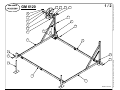
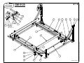
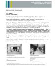
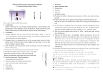
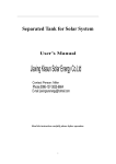
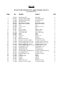
GM 6120
STRUCTURE PRINCIPALE / MAIN FRAME (60-0011)
(Novembre 2012)
ITEM
NO
1
2
3
4
5
6
7
8
9
10
11
12
13
14
15
16
17
18
19
20
21
22
23
24
25
26
27
28
29
30
31
32
33
34
40-0010
40-0011
21-3003
40-0006
40-0012
40-0013
20-3026
58-0002
40-2001
40-3001
21-3011
30-1002
58-0004
30-2003
21-3013
31-1007
31-1001
31-1003
31-0209
31-0213
31-0215
31-1010
31-1012
33-0003
33-0009
32-0011
32-0003
32-0015
30-1201
21-3014
30-0003
40-4011
21-3017
31-1004
PIÈCES
PARTS
Structure de Côté
Structure Avant & Arrière
Stabilisateur Secondaire
Structure en "H"
Structure du Lit (Avant)
Structure du Lit (Arrière)
Tube
Lit 2" x 6" x 10'
Patte
Roue du Treuil
Poignée de Roue
Treuil "DLB-1200"
Poulie
Cable
Tube 1.25"
Manille
Boulon œil 3/8 x 2.5"
Boulon en "U" 3/8 x 1.5 pipe
Boulon Hexagon 3/8-16 x 2-1/2"
Boulon Hexagon 3/8-16 x 3-1/2"
Boulon Hexagon 3/8-16 x 4"
Boulon à Épaulement 1/2 x 1-3/4"
Tire fond 3/8 x 1-1/4"
Rondelle plate 3/8
Rondelle Frein 3/8
Écrou Hexagon Galvanisé 3/8-16
Écrou Nylon 3/8-16
Écrou Hexagon 1/2-20
Ressort
Loquet de Patte
Goupille
Support
Plaque 3/8 x 2 x 4
Boulon en "U" 3/8 x 2 pipe
Side frame
Front & Back frame
Secondary brace
"H" frame
Bunks frame (Front)
Bunks frame (Back)
Tube
Bunks 2" x 6" x 10'
Leg
Wheel for winch
Spinner knob
Winch "DLB-1200"
Pulley
Cable
Spacer 1.25"
Shackle
Eye bolt 3/8 x 2.5"
"U" bolt 3/8 x 1.5 pipe
Hexagon bolt 3/8-16 x 2-1/2"
Hexagon bolt 3/8-16 x 3-1/2"
Hexagon bolt 3/8-16 x 4"
Shoulder bolt 1/2 x 1-3/4"
Lag bolt 3/8 x 1-1/4"
Flat washer 3/8
Lock washer 3/8
Hexagon nut Galvanize 3/8-16
Lock Nut 3/8-16
Hexagon nut 1/2-20
Spring
Leg pin
Hitch pin
Support
Plaque 3/8 x 2 x 4
"U" bolt 3/8 x 2 pipe
QTÉ.
2
2
2
2
1
1
2
2
4
1
1
1
2
1
2
2
2
1
18
12
4
1
8
10
2
2
45
1
1
4
4
4
4
4
DE L'ESTRIE
GM 6120
21
1
10
29
22
12
24
27
LAC BROME (QUÉBEC)
28
21
3
11
27
19
27
9
2
1
200812 / 60-0011
Ce dessin ne peut être reproduit sans notre autorisation
1/2
This drawing cannot be reproduce without our authorization
LES QUAIS
24
2
31
30
27
19
2/2
GM 6120
LAC BROME (QUÉBEC)
13
16
4
27
20
14
18
24
27
17
Ce dessin ne peut être reproduit sans notre autorisation
LES QUAIS
DE L'ESTRIE
15
25
24
DETAIL A
5
8
4
A
23
6
32
7
34
33
27
19
201211 / 60-0011
This drawing cannot be reproduce without our authorization
26
GM 6120
60 - 0011
03/2013
Français
Assemblage ;
* L’assemblage doit se faire de préférence sur un terrain plat.
* Évitez de serrer les boulons et les écrous avant de terminer l’assemblage.
* Afin de faciliter la recherche des pièces lors de l’assemblage, faites l’inventaire des boulons, des rondelles,
des écrous, etc.
* Lire le guide de Précautions avant l’utilisation de l’élévateur.
Page 1 / 2
1. Insérez les pattes réglables (# 9) dans les structures de coté (# 1).
2. Insérez les verrous de patte (# 30 et # 31).
3. Installez la structure avant et arrière (# 2) et insérez ensuite les boulons et les écrous.
4. Installez les stabilisateurs secondaires (# 3) et insérez ensuite les boulons et les écrous.
5. Serrez maintenant les boulons et les écrous.
6. Installation du treuil (# 12), de la roue (# 10) et de la poignée pour roue (# 11).
Page 2 / 2
1. Installez la structure en H (# 4) à la base avant et arrière (# 2) et insérez ensuite les boulons et les écrous.
2. Positionnez la structure du lit avant et arrière (# 5 et # 6) à la structure en H (# 4) et insérer ensuite les
boulons et les écrous.
3. Installez la structure de coté du lit (# 7) à la structure du lit avant et arrière (# 5 et # 6) et insérez ensuite les
boulons et les écrous.
4. Serrez maintenant les boulons et les écrous (serrez mais ne pas écraser le profilé en U).
5. Installez les poulies (# 13) à la structure du lit avant (# 5).
6. Installez le câble du treuil (# 14) : attachez l’extrémité du câble au boulon en U (# 18), insérez le câble dans
les poulies et attachez-le au treuil.
7. Soulevez le lit en tournant la roue dans le sens des aiguilles d’une montre.
8. Installez les tubes (# 32) des guides centralisateurs à la structure avant et arrière du lit et insérez ensuite les
boulons en U (# 34), plaque (# 33) et les
écrous.
9. Installez les deux guides centralisateurs (# 8) aux tubes des guides (# 32).
10. Ajustez les guides en fonction de la largeur de votre catamaran. Il est conseiller de laisser environ 1
pouces (25.4 mm) de chaque coté des flotteurs.
English
Assembly;
* Assembly must be done preferably on flat ground.
* Do not tighten the nuts and bolts before assembly is complete.
* To facilitate the search for parts at the time of assembly, make an inventory of the bolts, washers, nuts, etc.
* Read the Safety Precaution guidelines before using the hoist.
Page 1 / 2
1. Insert the adjustable legs (#9) in the side structures (#1).
2. Insert the leg locks (#30 and #31).
3. Install the forward and rear structure (#2) and then insert the bolts and the nylon nuts.
4. Install the secondary stabilizers (#3) and then insert the bolts and the nylon nuts.
5. Now tighten the bolts and the nylon nuts.
6. Installation of the winch (#12), wheel (#10) and wheel handle (#11).
Page 2 / 2
1. Install the structure in H (#4) at the forward and rear base (#2) and then insert the bolts and the nylon
nuts.
2. Place the forward and rear bunk structure (#5 and #6) on the structure in H (#4) and insert the bolts and
nylon nuts.
3. Install the structure on the side of the bunk (#7) on the forward and rear bunk structure (#5 and #6) and
insert the bolts and nylon nuts.
4. Now tighten the bolts and nylon nuts (tighten but do not crush the profile in U).
5. Install the pulleys (#13) on the front bunk structure (#5).
6. Install the winch cable (#14): attach the end of the cable to the bolt in U (#18), insert the cable in the
pulleys and attach it to the winch.
7. Raise the bunk, turning the wheel clockwise.
8. Install the tubes (#32) of the central guides on the forward and rear structure of the bunk and then insert
the bolts in U (#34), plate (#33) and the nylon nuts.
9. Install the two central guides (#8) on the tubes of the guides (#32).
10. Adjust the guides according to the width of your catamaran. It is recommended to leave about one inch
(25.4 mm) on each side of the floats.