1
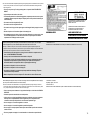
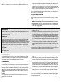
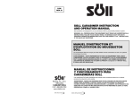
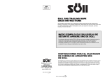
I112
9720018
INSPECTION AND MAINTENANCE LOG
I112
SERIAL NUMBER
MODEL NUMBER
DATE PURCHASED
INSPECTOR
8327 RETRACTABLE
LANYARD OPERATION AND
MAINTENANCE MANUAL
WARNING: ALL PERSONS USING THIS EQUIPMENT MUST READ AND
UNDERSTAND ALL INSTRUCTIONS. FAILURE TO DO SO MAY RESULT
IN SERIOUS INJURY OR DEATH.
DATE
The Miller 8327 Retractable Lanyards are self-contained retractable lanyards
designed to be used in applications where fall protection in combination with
unrestricted worker mobility is needed.
INSPECTION ITEMS NOTED
I. REQUIREMENTS
A. WARNINGS AND LIMITATIONS
Proper precautions should always be taken to remove any obstructions, debris
and other material from the work area that could cause injuries or interfere with
the operation of the unit. Caution should also be taken to insure that all
equipment will be clear of all other recognized hazards and that proper
ventilation has been provided in the work area.
MAINTENANCE PERFORMED
MANUEL D’INSTRUCTIONS
D’UTILISATION ET D’ENTRETIEN
FILIN DE SÉCURITÉ
RÉTRACTABLE 8327
REGISTRE D’INSPECTION ET D’ENTRETIEN
NUMÉRO DE SÉRIE
NUMÉRO DE MODÈLE
DATE D’ACHAT
INSPECTEUR
DATE
AVERTISSEMENT : TOUTE PERSONNE UTILISANT CET ÉQUIPEMENT
DOIT LIRE ET COMPRENDRE TOUTES LES INSTRUCTIONS.
L’ABSENCE DE TELLES PRÉCAUTIONS POURRAIT PROVOQUER DES
BLESSURES GRAVES OU MORTELLES.
DÉTAILS NOTÉS À L’INSPECTION
Les filins de sécurité rétractables Miller 8327 sont des filins rétractables
autonomes conçus pour l’utilisation par les travailleurs dans des conditions où
une protection antichute combinée à une mobilité totale est nécessaire.
ENTRETIEN EFFECTUÉ
I. EXIGENCES
A. AVERTISSEMENTS ET LIMITATIONS
Des précautions appropriées devraient toujours êtres prises pour éliminer de la
zone de travail tous les débris, obstructions et autres matériaux susceptibles de
provoquer des blessures ou d’entraver le fonctionnement du produit. Des
MANUAL DE FUNCIONAMIENTO
Y MANTENIMIENTO- CUERDA
DE SEGURIDAD RETRACTIL 8327
REGISTRO DE INSPECCION Y MANTENIMIENTO
NUMERO DE SERIE
NUMERO DE MODELO
FECHA DE COMPRA
INSPECTOR
DETALLES OBSERVADOS EN LA INSPECCION
MANTENIMIENTO EFECTUADO
ADVERTENCIA: TODAS LAS PERSONAS QUE UTILICEN ESTE EQUIPO
DEBEN LEER Y COMPRENDER TODAS LAS INSTRUCCIONES. DE LO
CONTRARIO SE PUEDEN PRODUCIR LESIONES GRAVES O
MORTALES.
FECHA
Franklin, PA U.S.A.
800-873-5242
FAX 800-892-4078
www.cdalloz.com
Las cuerdas de seguridad retráctiles 8327 de Miller son cuerdas retráctiles
autónomas diseñadas para ser usadas en tales aplicaciones donde se necesita
protección contra caídas junto con movilidad no restringida del trabajador.
I. REQUERIMIENTOS
A. ADVERTENCIAS Y LIMITACIONES
Siempre se deben tomar las precauciones apropiadas para eliminar del área de
trabajo cualquier obstrucción, escombros y otros materiales que puedan causar
lesiones o interferir con el funcionamiento del equipo. Asimismo, se deben
Note: users should be familiar with pertinent regulations governing this equipment. All individuals who use this product
must be correctly instructed on how to use the system, and must read and understand the following instructions
before using the unit.
• For use by one person only. The design working load is 310 pounds—DO NOT EXCEED THIS
WEIGHT.
• Only trained personnel should use this device.
• To minimize the potential for accidental disengagement, a competent person must ensure system
compatibility. Make sure snap hooks keepers completely close and are positioned so that they are
never load bearing.
AVERTISSEMENT : RETIRER DU SERVICE. CE
DISPOSITIF A ÉTÉ SOUMIS À DES FORCES
D’ARRÊT DE CHUTE.
• Do not use the unit if the lanyard doesn’t retract.
• Do not use the unit if the lanyard doesn’t lock.
ADVERTENCIA: PONER FUERA DE SERVICIO.
ESTE EQUIPO HA ESTADO SOMETIDO A
FUERZAS DE DETENCION DE CAIDAS.
• Do not use the unit if any part of the system appears to be damaged. Visually inspect prior to each
use.
• Discard and replace unit if it has been subject to fall arresting forces.
WARNING LABEL
• Do not attempt to service this device; if it does not operate satisfactorily or requires repairs, return
the unit to Miller Equipment or an authorized service center for repairs. Repairs are limited to
replacement of the webbing line and/or snap hook.
mesures devraient également êtres prises pour vérifier l’absence de tout autre risque connu susceptible
d’affecter l’équipement, et qu’une ventilation adéquate est assurée dans la zone de travail.
LOAD INDICATOR FLAG
SIGNE INDICATEUR DE CHARGE
BANDERA INDICADORA DE CARGA
FABRIQUÉ AUX U.S.A.
INDIQUER LA DATE DE PREMIÈRE UTILISATION (OU D’INSPECTION ANNUELLE PAR LA SUITE)
Remarque : L’utilisateur doit toujours avoir une bonne connaissance des règlements pertinents régissant cet
équipement. Toute personne utilisant ce produit doit avoir reçu les instructions adéquates concernant l’utilisation du
système et doit lire et comprendre les instructions suivantes avant l’utilisation.
• Pour utilisation par une seule personne. La charge de service définie à la conception est de 310
livres — NE PAS EXCÉDER CETTE CHARGE.
• Seul un personnel convenablement formé devrait utiliser ce dispositif.
• Pour minimiser les risques de séparation accidentelle, une personne compétente doit veiller à la
compatibilité des composants du système. S’assurer que les cliquets des mousquetons se
ferment entièrement et soient positionnés afin de ne jamais supporter de charge.
• Ne pas utiliser le dispositif si le filin ne se rétracte pas.
• Ne pas utiliser le dispositif si le filin ne se bloque pas.
• Ne pas utiliser le dispositif si un composant quelconque semble être endommagé. L’inspecter
visuellement avant chaque utilisation.
• Mettre le dispositif hors service et le remplacer s’il a été soumis à des forces d’arrêt de chute.
tomar medidas para asegurarse de que no existen otros riesgos comunes susceptibles de afectar el equipo y
que se ha provisto ventilación adecuada en el área de trabajo.
CAPACIDAD 310 LIBRAS
MATERIAL: NILON 1-3/4” X 3/64”
Nota: Los usuarios deben estar familiarizados con los reglamentos pertinentes que rigen este equipo. Todas las
personas que utilicen este producto deben recibir las instrucciones correctas sobre el uso de este sistema y deben
leer y comprender las siguientes instrucciones antes de usar este equipo.
HECHO EN EE.UU.
MARQUE LA FECHA DEL PRIMER USO (O DE LA INSPECCION ANUAL DE AHI EN ADELANTE)
• Para uso por una persona solamente. La carga nominal de trabajo es de 310 libras—NO EXCEDA
ESTE PESO.
• Solamente el personal entrenado debe usar este dispositivo.
• A fin de reducir a un mínimo la posibilidad de desenganche accidental, una persona competente
debe supervisar la compatibilidad del sistema. Asegúrese de que los mosquetones estén
colocados de manera que el dispositivo de cierre nunca esté soportando carga.
• No use este equipo si la cuerda de seguridad no se retracta.
• No use este equipo si la cuerda de seguridad no queda bien bloqueada.
• No use el equipo si cualquier pieza del sistema parece estar dañada. Inspecciónelo visualmente
antes de cada uso.
• Descarte y reemplace este equipo si ha estado sometido a las fuerzas de una parada de caída.
2
15
WARNING LABEL
• Do not lubricate this device.
MODEL: 8327 RETRACTABLE LANYARD
DATE:
LENGTH: 10 FT.
SERIAL NO.
BEFORE USE: CHECK LIFELINE RETRACTABLE BY PULLING OUT SEVERAL FEET OF WEBBING AND
ALLOWING IT TO RETRACT UNDER LIGHT TENSION. CHECK BRAKING ACTION BY APPLYING A SHARP
PULL TO THE LIFELINE. THE BRAKES MUST ENGAGE. RELEASE THE TENSION AND ALLOW THE LIFELINE
TO RETRACT SLOWLY INTO THE UNIT. THE LIFELINE SHOULD RETRACT COMPLETELY. REMOVE FROM
SERVICE IF ANY DAMAGE IS DETECTED.
• The lanyard must be kept clean and free of contaminants.
WARNING: CONNECTORS AND ANCHORAGE POINTS MUST BE COMPATIBLE AND ABLE TO SUPPORT A
5,000 LB. STATIC LOAD.
• Allow 3 feet of clearance in the event of a free fall.
WARNING: MANUFACTURER’S INSTRUCTIONS SUPPLIED WITH THIS PRODUCT AT TIME OF SHIPMENT
MUST BE FOLLOWED: FAILURE TO DO SO COULD RESULT IN SERIOUS INJURY OR DEATH. CONTACT
MILLER EQUIPMENT IF INSTRUCTION MANUAL IS NEEDED.
THIS PRODUCT MEETS ANSI Z359.1, A10.14 & OSHA REQUIREMENTS AT THE TIME OF SHIPMENT.
MAX. ARRESTING FORCE: 900 LBS.
MAX. ARRESTING DISTANCE: 3'
CAPACITY: 310 LBS.
MATERIAL: 1—3/4" X 3/64" POLYESTER
MADE IN USA
MARK DATE OF FIRST USE (OR ANNUAL INSPECTION THEREAFTER)
ÉTIQUETTE D’AVERTISSEMENT
MODÈLE : FILIN DE SÉCURITÉ RÉTRACTABLE 8327
DATE :
LONGUEUR : 10 PI
NO_DE SÉRIE
AVANT UTILISATION : VÉRIFIER LA RÉTRACTION DU FILIN EN TIRANT PLUSIEURS PIEDS DE SANGLE ET EN
LES LAISSANT SE RÉTRACTER SOUS UNE LÉGÈRE TENSION. VÉRIFIER LE MÉCANISME DE FREINAGE EN
TIRANT FORTEMENT LE FILIN. LES FREINS DEVRONT S’EMBRAYER. RELÂCHER LA TENSION ET LAISSER
LE FILIN SE RÉTRACTER LENTEMENT DANS LE DISPOSITIF. LE FILIN DEVRAIT SE RÉTRACTER
COMPLÈTEMENT. LE RETIRER DU SERVICE SI UN DOMMAGE QUELCONQUE EST DÉTECTÉ.
AVERTISSEMENT : LES CONNECTEURS ET LES POINTS D’ANCRAGE DOIVENT ÊTRE COMPATIBLES ET
POUVOIR SUPPORTER UNE CHARGE STATIQUE DE 5000 LB.
AVERTISSEMENT : LES INSTRUCTIONS DU FABRICANT FOURNIES AVEC CE PRODUIT AU MOMENT DE
L’EXPÉDITION DOIVENT ÊTRE SUIVIES. LE NON-RESPECT DE CES INSTRUCTIONS POURRAIT CAUSER
DES BLESSURES GRAVES OU MORTELLES. CONTACTEZ MILLER EQUIPMENT SI VOUS AVEZ BESOIN
D’UN NOUVEAU MANUEL.
CE PRODUIT EST CONFORME AUX NORMES ANSI Z359.1, A10.14 ET OSHA AU MOMENT DE L’EXPÉDITION.
FORCE D’ARRÊT MAX. 900 LB
DISTANCE D’ARRÊT MAX. 3 PI
CAPACITÉ : 310 LB
MATÉRIAU : NYLON 1-3/4 PO X 3/64 PO
ETIQUETA DE ADVERTENCIA
MODELO: CUERDA DE SEGURIDAD RETRACTIL 8327
FECHA:
LARGO: 10 PIES
NO. DE SERIE:
ANTES DEL USO
VERIFIQUE LA RETRACCION DE LA CUERDA DE SEGURIDAD TIRANDO HACIA AFUERA VARIOS PIES DE
CINCHA Y DEJANDOLA QUE SE RETRAIGA BAJO UNA TENSION LEVE. VERIFIQUE EL MECANISMO DE
FRENAJE DANDO UN TIRON FUERTE Y FIRME A LA CUERDA. LOS FRENOS DEBEN ENGANCHARSE. ALIVIE
LA TENSION Y DEJE QUE LA CUERDA SE RETRAIGA LENTAMENTE HACIA LA CAJA. LA CUERDA DEBE
RETRACTARSE COMPLETAMENTE. PONER FUERA DE SERVICIO SI SE DETECTA DAÑO.
ADVERTENCIA: LOS CONECTORES Y LOS PUNTOS DE ANCLAJE DEBEN SER COMPATIBLES Y CAPACES
DE SOPORTAR UNA CARGA ESTATICA DE 5.000 LIBRAS.
ADVERTENCIA: SE DEBEN SEGUIR LAS INSTRUCCIONES DEL FABRICANTE SUMINISTRADAS CON EL
EQUIPO AL MOMENTO DE SER DESPACHADO. DE LO CONTRARIO SE PUEDEN PRODUCIR LESIONES
GRAVES O MORTALES. PONGASE EN CONTACTO CON MILLER EQUIPMENT SI NECESITA UN MANUAL
DE INSTRUCCIONES.
ESTE PRODUCTO CUMPLE LAS NORMAS ANSI Z359.1, A10.14, Y OSHA 1926.502, OSHA 1910.66, MOMENTO
DEL EMBARQUE.
FUERZA DE PARADA DE CAIDA MAX. 900 LIBRAS
DISTANCIA DE PARADA MAX. 3’
14
• Anchor points must be capable of supporting 5000 lbs. per worker.
• The equipment should be installed and used in such a manner as to reduce the potential for a
swing fall.
• Never work above the device, unless mounted for use within a structure (e.g. lifts, in accordance
with installation instructions.
• Never use the device as a restraint or positioning device.
• Never allow the lanyard to become slack or to pass under or entwine around the user’s arms, legs,
or any other obstacle.
• Do not allow webbing lanyard to come in contact with high temperature surfaces, welding, heat
sources, electrical hazards, or moving machinery.
• Do not tie knots in lanyard, or wrap around sharp, rough edges, or small diameter structural
members.
• Ne pas tenter de réparer ce dispositif; s’il ne fonctionne pas de façon satisfaisante ou nécessite
des réparations, le retourner à Miller Equipment ou à un centre de service autorisé pour effectuer
les réparations. Les réparations sont limitées au remplacement de la sangle et/ou du mousqueton.
• Ne pas lubrifier ce dispositif.
• Le filin de sécurité doit être gardé propre et exempt de substances contaminantes.
• Les points d’ancrage doivent pouvoir supporter 5000 lb par travailleur.
• L’équipement devrait être installé et utilisé de façon à réduire le risque éventuel d’une chute pendulaire.
• Prévoir une distance libre de 3 pi pour une chute libre éventuelle.
• Ne jamais travailler au-dessus du dispositif, à moins qu’il ne soit installé pour utilisation au sein
d’une structure (élévateur p. ex.) conformément aux instructions d’installation ci-dessous.
• Ne jamais utiliser le dispositif comme système de positionnement ou de retenue.
• Ne jamais laisser le filin se détendre ou passer ou s’enrouler autour des bras ou des jambes de
l’utilisateur, ou de tout autre obstacle.
• Ne pas laisser la sangle du filin entrer en contact avec des surfaces très chaudes, de la soudure,
des sources de chaleur, des risques électriques, ou de la machinerie mobile.
• No intente reparar este equipo; si no funciona satisfactoriamente o necesita reparación, devuelva
el equipo a Miller Equipment o a un centro de servicio autorizado para su reparación. Las
reparaciones se limitan al reemplazo de la cuerda y/o el gancho de resorte.
• No lubrique este dispositivo.
• La cuerda de seguridad debe mantenerse limpia y libre de contaminantes.
• Los puntos de anclaje deben ser capaces de soportar 5000 libras por trabajador.
• El equipo debe ser instalado y usado de tal manera que se reduzca el potencial de una caída
oscilante.
• Deje un espacio libre de 3 pies en caso de una caída libre.
• Nunca trabaje más arriba del dispositivo, a menos que haya sido instalado para uso dentro de una
estructura (por ej. ascensores) de acuerdo con las instrucciones de instalación que se indican a
continuación.
• Nunca use el dispositivo como un mecanismo de restricción o posicionamiento.
• Nunca permita que la cuerda tenga flojedad o que pase debajo o se enrolle en los brazos, piernas
del usuario o en cualquier otro obstáculo.
3
• Use in highly corrosive or caustic environment dictates a more frequent inspection and servicing
program to ensure the integrity of the unit is maintained. Consult Miller if in doubt of chemical
effect.
MATERIALS
HOUSING:
WEBBING:
THREAD:
SNAPHOOK:
• Employers must provide for prompt rescue in the event of a fall.
• This product is designed for personal fall protection. Never use fall protection equipment for
purposes other than which it is designed.
B. SYSTEM COMPATIBILITY
Miller 8327 retractable lanyards are designed for use with Miller approved components. Substitution or
replacement with non-approved components could endanger the compatibility within the system and may
affect the reliability and safety of the total system. Substitution or replacement must be accomplished only
under the supervision of a qualified person. It is recommended that the worker wear a Miller full-body harness
to distribute the fall arresting forces over the body and to keep an unconscious or injured worker in an upright
position.
Proper use of fall arrest systems can save lives and reduce the potential of serious injuries from a fall. The
user must be aware that forces experienced during the arrest of a fall or prolonged suspension may cause
bodily injury. Consult a physician if there is any question about the user’s ability to use this product.
Pregnant women and minors must not use this product.
• Ne pas faire de noeud dans le filin, ni l’enrouler autour de bords aigus, rugueux, ou de pièces de
construction de petit diamètre.
TECHNICAL
MAX. WORKING LOAD:
ULTIMATE STRENGTH:
LIFELINE TENSION:
STOPPING DISTANCE:
310 LBS.
3000 LBS.
3 TO 4 LBS.
24"
(220 LB. — QUICK RELEASE)
ARRESTING FORCE: 900 LBS. (APPROX.)
STRENGTH TEST: 300 LB. 4' FREE FALL
WEIGHT: 3 LBS.
CERTIFICATION
THIS PRODUCT MEETS OSHA 1926.502, 1910.66, ANSI Z359.1, A10.14 AT THE TIME OF SHIPMENT.
MATÉRIAUX
CARTER :
SANGLE :
FIL :
MOUSQUETON :
• L’utilisation dans un environnement hautement corrosif ou caustique impose une inspection plus
fréquente et un programme d’entretien pour assurer le maintien de l’intégrité du produit. Contacter
Miller en cas de doute d’effets chimiques.
• Les employeurs doivent assurer un rapide secours en cas de chute.
• Ce produit est conçu pour la protection individuelle contre les chutes. Ne jamais utiliser un
équipement de protection antichute dans une application autre que celle pour laquelle il est conçu.
B.
COMPATIBILITÉ DES ÉLÉMENTS DU SYSTÈME
Les filins de sécurité rétractables Miller 8327 sont conçus pour l’utilisation avec des composants homologués
par Miller. La substitution ou le remplacement de composants par des composants non homologués pourrait
dégrader les caractéristiques de compatibilité au sein du système et peuvent affecter la fiabilité et la sécurité
de l’ensemble du système. La substitution ou le remplacement ne doit être effectué que sous la supervision
d’une personne qualifiée. Il est recommandé que le travailleur porte un harnais complet Miller pour répartir les
forces d’arrêt de chute dans tout le corps et garder un travailleur blessé ou inconscient en position verticale.
• No permita que la cuerda de seguridad tenga contacto con superficies a alta temperatura,
soldaduras, fuentes de calor, riesgos eléctricos o maquinaria en movimiento.
• No ate nudos en la cuerda de seguridad, ni la pase sobre bordes afilados o ásperos o por
miembros estructurales de diámetro pequeño.
• El uso en un ambiente corrosivo o cáustico requiere inspección más frecuente y un programa de
servicio para asegurar de que se mantenga la integridad del equipo. Póngase en contacto con
Miller Equipment en caso de duda sobre el efecto químico.
• Los empleadores deben proveer rescate inmediato en caso de una caída.
• Este equipo está diseñado para protección personal contra caídas. Nunca use el equipo de
protección contra caídas para propósitos que no sean aquellos para los cuales ha sido diseñado.
B. COMPATIBILIDAD DEL SISTEMA
Las cuerdas de seguridad retráctiles 8327 de Miller han sido diseñadas para ser usadas con los componentes
aprobados por Miller. La sustitución o reemplazo con componentes no aprobados puede dañar la
compatibilidad dentro del sistema y puede afectar la confiabilidad y seguridad del sistema total. La sustitución
o reemplazo debe ser efectuada solamente bajo la supervisión de una persona calificada. Se recomienda que
el trabajador use un arnés para todo el cuerpo para distribuir las fuerzas de parada de caída en todo el cuerpo
y mantener un trabajador inconsciente o lesionado en posición vertical.
4
STAMPED STEEL, THERMOPLASTIC COVER
1-3/4" POLYESTER
NO. 415 6 CORD BONDED, 3 STRAND POLYESTER
DROP FORGED STEEL
ACIER ESTAMPÉ, ENVELOPPE THERMOPLASTIQUE
POLYESTER 1-3/4 PO
CÂBLÉ 6 FILS, POLYESTER 3 BRINS Nº 415
ACIER ESTAMPÉ
CARACTÉRISTIQUES TECHNIQUES :
CHARGE DE SERVICE MAX. : 310 LB
RÉSISTANCE LIMITE : 3000 LB
TENSION AU FILIN : 3 À 4 LB
DISTANCE D’ARRÊT : 24 PO (220 LB - DÉGAGEMENT RAPIDE)
FORCE D’ARRÊT : 900 LB (APPROX.)
TEST DE RÉSISTANCE : 300 LB CHUTE LIBRE DE 4 PI
POIDS : 3 LB
CERTIFICATION
CE PRODUIT EST CONFORME AUX NORMES OSHA 1926.502, 1910.66, ANSI Z359.1, A10.14 AU MOMENT DE
L’EXPÉDITION.
MATERIALES
CAJA:
CINCHA:
CUERDA:
GANCHO DE RESORTE:
CARACTERÍSTICAS TÉCNICAS:
CARGA DE TRABAJO MÁXIMA:
RESISTENCIA LÍMITE:
TENSIÓN DE LA CUERDA:
DISTANCIA DE PARADA:
FUERZA DE PARADA:
PRUEBA DE RESISTENCIA:
PESO:
ACERO ESTAMPADO, CUBIERTA TERMOPLASTICA
POLIESTER DE 1-3/4”O, ACERO INOXIDABLE
CABLE LIGADO DE 6 HILOS, DE POLIESTER DE 3 TORONES NO. 415
ACERO FORJADO EN CALIENTE
310 LBS.
3000 LBS.
3 A 4 LBS.
24” (220 LB. - DESENGANCHE RAPIDO)
900 LBS. (APROX.)
300 LBS. CAÍDA LIBRE DE 4’
3 LIBRAS
CERTIFICACION
ESTE PRODUCTO CUMPLE LAS NORMAS OSHA 1926.502, OSHA 1910.66, ANSI A10.14, ANSI Z359.1 AL
MOMENTO DEL EMBARQUE.
13
MILLER 8327 RETRACTABLE LANYARD
FILIN DE SÉCURITÉ RÉTRACTABLE MILLER 8327
CUERDAS DE SEGURIDAD RETRACTILES MILLER 8327
II. INSTALLATION
The 8327 retractable lanyard must be mounted to an
anchorage capable of supporting a 5,000 pound tensile
load, or the anchorage must be designed, installed,
and used under the supervision of a qualified person
as part of a complete fall arrest system which
maintains a safety factor of two. The 8327 must be
used in one of the following arrangements.
1. Mounted to an overhead anchor by the swivel
attachment using a locking carabiner (see fig. 1), or
ANCHOR
ANCRAGE
ANCLAJE
CARABINER
MOUSQUETON
MOSQUETON
SWIVEL
ÉMERILLON
ESLABON
HOUSING
CARTER
CAJA
21” APPROX. WHEN FULLY
RETRACTED
APPROX. 21 PO QUAND
ENTIÈREMENT RÉTRACTÉ
APROX. 21” CUANDO ESTA
COMPLETAMENTE
RETRAIDO
LOAD INDICATOR
INDICATEUR DE CHARGE
INDICADOR DE CARGA
WEBBING
SANGLE
CINCHA
LOCKING SNAP
MOUSQUETON À VERROUILLAGE
MOSQUETON CON CIERRE
2. Mounted within a structure (e.g. lift) to an anchorage
designed, installed and used under the supervision
of a qualified person. Mounting the 8327 retractable
lanyard below the attachment point of the lanyard to
the user requires special provisions. The structure
must have support members (such as guard rails)
that will have the height and strength to function as
bearing points for the retractable line in the event of
a fall. These support members must have sufficient
FIG. 1
La bonne utilisation des systèmes d’arrêt de
chutes peut sauver des vies et réduire le risque de
blessures sérieuses à la suite d’une chute.
L’utilisateur doit être avisé que les forces exercées
lors de l’arrêt d’une chute ou d’une suspension
prolongée peuvent causer des blessures.
Consulter un médecin si vous avez des questions
concernant la capacité de l’utilisateur d’utiliser ce
produit. Les femmes enceintes et les enfants ne
doivent pas utiliser ce produit.
II. INSTALLATION
Le filin de sécurité rétractable 8327 doit être suspendu
à un dispositif d’ancrage en hauteur capable de
supporter une charge de traction de 5000 lb, ou le
dispositif d’ancrage doit être conçu, installé et utilisé
sous la supervision d’une personne qualifiée,
comme partie d’un système complet d’arrêt de chute
maintenant un facteur de sécurité de deux. Le filin
de sécurité 8327 doit être utilisé dans l’une des
dispositions suivantes.
4 1/4"
12
El uso correcto de los sistemas de protecciÛn
contra caÌdas puede salvar muchas vidas y reducir
el potencial de lesionamiento grave como
consecuencia de una caÌda. El usuario debe estar
consciente de que las fuerzas experimentadas
durante la supresiÛn de una caÌda o la suspensiÛn
prolongada pueden causar lesionamiento corporal.
Consulte a un mÈdico si existe cualquier pregunta
sobre la capacidad del usuario en utilizar este
producto. Las mujeres embarazadas y los menores
no deben hacer uso de este producto.
AVERTISSEMENT : Le mousqueton doit
être verrouillé.
II. INSTALACION
ADVERTENCIA: El mosquetón debe
estar firmemente cerrado.
Las cuerdas de seguridad retráctiles 8327 deben ser
instaladas en un punto de anclaje capaz de soportar
una carga de tracción de 5.000 libras, o el anclaje
debe ser diseñado, instalado y usado bajo la
supervisión de una persona calificada como parte de
un sistema completo de detención de caídas que
mantenga un factor de seguridad de dos. El modelo
8327 debe ser usado en una de las siguientes formas.
WARNING: Carabiner must be locked.
5
FIG. 2
SUPPORT MEMBER
(CROSS SECTION SHOWN,
COMPLETE ENCLOSURE
IN DIRECTION OF ALL
POSSIBLE FALLS
REQUIRED).
SUPPORT (VUE EN
COUPE; UN ENTOURAGE
COMPLET DANS TOUTES
LES DIRECTIONS DE
CHUTES POSSIBLES EST
NÉCESSAIRE)
SOPORTE (SECCION
TRANSVERSAL; ES
NECESARIO UN RECINTO
CERRADO EN TODAS LAS
DIRECCIONES DE CAIDAS
POSIBLES.)
C. REMISAGE
Remiser le produit dans un lieu propre et sec quand il n’est pas utilisé. Le filin devrait être entièrement rétracté
dans le dispositif quand il n’est pas utilisé. L’absence de telles précautions pourrait provoquer un
affaiblissement prématuré du grand ressort résultant en une perte de rétraction du filin.
C. ALMACENAMIENTO
Guarde el dispositivo en un lugar limpio y seco cuando no esté en uso. La cuerda debe estar totalmente
retraída dentro de la caja cuando el dispositivo no se está usando. El incumplimiento de esta advertencia
puede causar debilitamiento prematuro del resorte principal resultando en una pérdida de retracción de la
cuerda de seguridad.
FLOOR
PLANCHER
PISO
8327 RETRACTABLE LANYARD
FILIN DE SÉCURITÉ RÉTRACTABLE 8327
CUERDA DE SEGURIDAD RETRACTIL 8327
FIGURE 2: ILLUSTRATES AN EXAMPLE OF SUPPORT MEMBERS FOR THE STRUCTURE.
FIGURE 2 : ILLUSTRE UN EXEMPLE DE SUPPORT DE STRUCTURE.
FIGURA 2: ILUSTRA UN EJEMPLO DE SOPORTES PARA LA ESTRUCTURA.
6
11
C. STORAGE
Store in a clean, dry location when not in use. The lanyard should be fully retracted into the unit when not in
use. Failure to do so may cause premature weakening of the mainspring resulting in a loss of lifeline retraction.
strength to support the force of the line bearing against it at any point and direction possible in a fall. The
user must be surrounded by these support members in the direction of all possible falls. All edges of the
support members that may contact the line during a fall must be sufficiently smooth and rounded or
chamfered (free of burrs and sharp edges) as to permit the lanyard line to lock without damage to the line
and without excessive friction to slow line locking. The structure design must be adequate to prevent it from
toppling when subject to the forces applied by the line in the event of a fall (see fig. 2).
The 8327 retractable lanyard must be inspected and tested satisfactorily before each use as described in
section III. Operation & Inspection. Before the user is subject to a fall hazard, connect the snap hook of the
unit onto the back d-ring of the user’s harness.
III. OPERATION & INSPECTION
A. GENERAL INSPECTION
Before use, inspect device for loose fasteners, bent, cracked, distorted, worn, malfunctioning, or damaged
parts.
B. GENERAL OPERATION
WARNING: The following operation checkpoints and inspections must be done prior to each use:
1. Anchorage Connection: Make sure the carabiner is properly seated and in the locked position between
the attachment swivel on the unit and the anchor point. The anchorage connector and anchorage point
must be capable of supporting 5000 lbs.
IV. FORMATION
L’utilisateur a la responsabilité de s’assurer qu’il a lu, compris et suivi toutes les instructions, et a reçu une
formation pour utiliser et entretenir ce dispositif. La formation devrait être répétée périodiquement et chaque
fois qu’il y a un changement de composants dans le système. La formation doit être effectuée sans exposer
l’utilisateur à un risque de chute.
V. ENTRETIEN
A. ENTRETIEN ET RÉPARATIONS
L’entretien et les réparations ne doivent être effectués que par un technicien qualifié homologué par Miller
Equipment, ayant reçu la formation appropriée pour les réparations et l’entretien des filins de sécurité/
dispositifs d’arrêt de chute de Miller Equipment. Le responsable de la sécurité de la compagnie doit tenir à jour
un registre des opérations d’inspection et d’entretien de cet équipement, avec dates des opérations. Seules
les pièces de rechange d’origine Miller sont homologuées pour l’utilisation dans ce dispositif. Veuillez contacter
votre distributeur Miller ou appelez le service à la clientèle de Miller Equipment au 1-800-873-5242 pour
obtenir un numéro d’autorisation de retour de marchandise.
B. NETTOYAGE
Nettoyer périodiquement l’extérieur du dispositif et essuyer le filin avec un linge humide et un détergent doux.
Sécher avec une serviette.
IV. ENTRENAMIENTO
Es responsabilidad del usuario asegurarse de que se lean y observen todas las instrucciones y de obtener
entrenamiento en el cuidado y uso de este dispositivo. El entrenamiento debe repetirse periódicamente y
siempre que haya algún cambio en los componentes dentro del sistema. El entrenamiento debe llevarse a
cabo sin exponer a la persona que está siendo entrenada al riesgo de sufrir una caída.
V. MANTENIMIENTO
A. REPARACION
La reparaciones deben ser efectuadas solamente por un técnico de servicio aprobado de Miller Equipment,
entrenado en la reparación y servicio de los sistemas/dispositivos salvavidas de parada de caídas de Miller
Equipment. El funcionario de seguridad de la compañía debe llevar un registro de todas las reparaciones y
fechas de inspecciones de este dispositivo. En este dispositivo se deben usar solamente repuestos originales
Miller. Póngase en contacto con su distribuidor Miller o con el Departamento de Servicio a los Clientes de
Miller Equipment llamando al 1-800-873-5242 para obtener un número de autorización para retorno de
mercaderías.
B. LIMPIEZA
Limpie periódicamente el exterior del dispositivo y frote la cuerda de seguridad con un paño húmedo y
detergente suave. Seque con una toalla.
10
1. Suspendu à un point d’ancrage en hauteur par l’émerillon d’accrochage à l’aide d’un mousqueton à
verrouillage (voir fig. 1), ou
2. Fixé à l’intérieur d’une structure (élévateur p. ex.) à un dispositif d’ancrage conçu, installé et utilisé sous la
supervision d’une personne qualifiée. Le montage du filin de sécurité rétractable 8327 à un niveau inférieur
à celui du point d’attachement du filin à l’utilisateur, demande des dispositions spéciales. La structure doit
avoir des supports (tels que garde-corps) ayant la hauteur et la solidité nécessaires pour servir de point
d’appui pour le filin rétractable en cas de chute. Ces supports doivent être assez solides pour supporter la
force du filin s’appuyant contre eux, à n’importe quel point et dans n’importe quelle direction, en cas de
chute. L’utilisateur doit être entouré par ces supports en direction de toute chute possible. Tous les bords
des supports susceptibles d’entrer en contact avec le filin durant une chute doivent être suffisamment lisses
et arrondis ou biseautés (sans barbures ni arêtes aiguës) pour permettre au filin de se bloquer sans
s’endommager et sans friction excessive ralentissant le blocage. Le concept de la structure doit être
adéquat pour empêcher le basculement quand soumis aux forces appliquées par le filin en cas de chute
(voir fig. 2).
Le filin de sécurité rétractable 8327 doit être inspecté et testé de façon satisfaisante avant chaque utilisation
comme décrit à la section III - Utilisation et inspection. Avant que l’utilisateur soit exposé à un risque de chute,
connecter le mousqueton du dispositif à l’anneau en D du dos du harnais de l’utilisateur.
1. Instalado en un anclaje superior mediante el eslabón giratorio de fijación usando un mosquetón de cierre.
(Ver Fig. 1), o
2. Instalado dentro de una estructura ( por ej. ascensor) en un anclaje diseñado, instalado y usado bajo la
supervisión de una persona calificada. El montaje de la cuerda de seguridad 8327 retráctil debajo del punto
de fijación de la cuerda en relación al usuario, requiere provisiones especiales. La estructura debe tener
soportes (tales como barandillas) que tendrán la altura y resistencia para funcionar como puntos de apoyo
para la cuerda retráctil en el caso de una caída. Estos soportes deben tener suficiente resistencia para
soportar la fuerza de la cuerda que se apoya en ellos, en cualquier punto y dirección posible, en caso de
una caída. El usuario debe estar rodeado por estos soportes en la dirección de todas las caídas posibles.
Todos los bordes de los soportes que puedan tener contacto con la cuerda durante una caída, deben ser
suficientemente suaves y redondeados o biselados (sin rebabas ni bordes afilados) de manera que la
cuerda de seguridad actúe debidamente sin dañarse y sin demasiada fricción que retarde el cierre de ésta.
El diseño de la estructura debe ser adecuado para evitar que se derribe cuando esté sometida a las
fuerzas aplicadas por la cuerda en caso de una caída (ver Fig. 2).
Antes de cada uso la cuerda de seguridad retráctil 8327 debe ser inspeccionada y probada para verificar que
esté en condiciones satisfactorias, según se describe en la Sección III - Operación e Inspección. Antes de
que el usuario sea sometido al riesgo de sufrir una caída, conecte el gancho de resorte del equipo en el anillo
en D trasero del arnés del usuario.
7
2. Lanyard Retraction: With the device in the mounted position, test the lanyard retraction and tension by
pulling out several feet of the lanyard and allow it to retract back into the unit. Always maintain a light tension
on the lifeline as it retracts. The lifeline should pull out freely and retract all the way back into the unit.
a. If the lifeline does not pull out smoothly or sticks when retracting, pull all of the lifeline out of the housing
and allow it to retract slowly under tension.
b. The lifeline should be checked regularly for signs of damage. Inspect for cuts, burns, corrosion, kinks,
frays, or worn areas. Inspect any sewing for loose, broken, or damaged stitches.
3. Braking Mechanism: The braking mechanism can be tested by grasping the lanyard and applying a sharp
steady pull downward which will engage the brakes. There should be no slippage of the lifeline while the
brakes are engaged. Once tension is released, the brakes will disengage and the unit will return to the
retractable mode.
4. Snap hook: Check the snap hook to be sure that it operates freely, locks, and the swivel operates
smoothly. Inspect the snap hook for any signs of damage to the keepers and any bent, cracked, or distorted
components.
5. Load Indicator: A fold sewn into the webbing lifeline above the snap hook serves as the impact indicator. A
warning flag is included and will be exposed should the lifeline be subjected to fall arresting forces.
UNITS THAT DO NOT PASS THIS INSPECTION OR HAVE BEEN SUBJECTED TO FALL ARRESTING
FORCES MUST BE REMOVED FROM SERVICE.
IV. TRAINING
It is the responsibility of the user to assure that they read, understand, and follow all instructions and are trained
in the care and use of this device. Training should be repeated periodically and any time there is a change of
components within the system. Training must be conducted without exposing the trainee to a fall hazard.
V. MAINTENANCE
A. SERVICING
Servicing must only be carried out by a Miller Equipment approved service technician trained in the repair and
service of Miller Equipment fall arrest lifeline systems/devices. A record log of all servicing and inspection
dates for this device must be maintained by the company safety officer. Only original Miller replacement parts
are approved for use in this device. Contact your Miller distributor or call Miller Equipment’s Customer Service
Department at 1-800-873-5242 for a return goods authorization number.
B. CLEANING
Periodically clean the exterior of the device and wipe the lanyard using a damp cloth and mild detergent.
Towel dry.
Inspect the impact indicator for signs of activation, bent, cracked or distorted components before each use.
III. UTILISATION ET INSPECTION.
A. INSPECTION GÉNÉRALE
Avant l’utilisation, inspecter le dispositif pour détecter les fermetures lâches, les pièces faussées, fissurées,
tordues, usées ou abîmées, ou dont le fonctionnement est défectueux.
B. UTILISATION GÉNÉRALE
AVERTISSEMENT : Les vérifications et inspections de fonctionnement suivantes doivent être
effectuées avant chaque utilisation :
1. Connexion d’ancrage : S’assurer que le mousqueton est correctement placé et en position fermée entre
l’émerillon d’accrochage du dispositif et le point d’ancrage. Le connecteur d’ancrage et le point d’ancrage
doivent pouvoir supporter 5000 lb.
2. Rétraction du filin : Le dispositif étant en position installée, vérifier la rétraction du filin et la tension en en
tirant plusieurs pieds puis en les laissant se rétracter dans le carter. Maintenir toujours une légère tension
sur le filin pendant qu’il se rétracte. Le filin devrait s’extraire librement et se rétracter complètement dans le
dispositif.
a. Si le filin ne se dégage pas facilement quand on le tire ou s’il se coince en se rétractant, le sortir
complètement du carter et le laisser se rétracter lentement sous tension.
coupures, brûlures, corrosion, pliures, effilochures ou parties usées. Inspecter toutes les coutures pour
détecter les points lâches, rompus, ou abîmés.
3. Mécanisme de freinage : Le mécanisme de freinage peut être testé en saisissant le filin et en le tirant
fortement et fermement vers le bas, ce qui embrayera les freins. Le filin ne devrait pas glisser quand les
freins sont embrayés. Une fois la tension relâchée, les freins se débrayeront et le dispositif redeviendra
rétractable.
4. Mousqueton : Vérifier le mousqueton pour s’assurer qu’il fonctionne librement, se verrouille et pivote bien.
Inspecter le mousqueton pour détecter tout signe de dommage aux cliquets et d’éléments faussés, fissurés
ou tordus.
5. Indicateur d’impact : Un repli cousu dans la sangle au-dessus du mousqueton sert d’indicateur d’impact.
Un signe d’avertissement est inclus et sera exposé si le filin est soumis à des forces d’arrêt de chute.
Inspecter l’indicateur d’impact avant chaque utilisation pour détecter les signes d’activation, les éléments
faussés, fissurés ou tordus.
LES DISPOSITIFS DONT L’INSPECTION A RÉVÉLÉ DES DÉFECTUOSITÉS OU AYANT ÉTÉ SOUMIS
À DES FORCES D’ARRÊT DE CHUTE DOIVENT ÊTRE MIS HORS SERVICE.
b. Le filin devrait être inspecté régulièrement pour détecter tout signe de dommage. Vérifier l’absence de
III. OPERACION E INSPECCION
A. INSPECCION GENERAL
Antes del uso, inspeccione el dispositivo para verificar si hay sujetadores sueltos, doblados, agrietados,
deformados, usados, que funcionen mal o piezas dañadas.
B. FUNCIONAMIENTO GENERAL
ADVERTENCIA: Antes de cada uso se deben realizar las siguientes verificaciones del
funcionamiento e inspecciones:
1. Conexión de Sujeción: Asegúrese de que el mosquetón esté debidamente asentado y cerrado entre el
eslabón giratorio de sujeción en el dispositivo y el punto de anclaje. El conector de sujeción y el punto de
anclaje deben ser capaces de soportar 5.000 libras.
2. Retracción de la Cuerda de Seguridad: Con el dispositivo ya instalado, pruebe la tensión y retracción de
la cuerda de seguridad haciendo salir varios pies de cuerda y déjandola retraerse hacia la caja. Siempre
mantenga una leve tensión en la cuerda de seguridad a medida que se retrae. La cuerda debe salir
libremente y retraerse completamente hacia la caja.
a. Si la cuerda no sale hacia afuera suavemente o se atasca cuando se está retrayendo, saque toda la
cuerda de la caja y déjela que se retraiga lentamente bajo tensión.
8
b. La cuerda debe ser revisada regularmente para verificar si tiene señas de daño. Inspeccione si tiene
cortes, quemaduras, corrosión, torceduras, hilachas o áreas desgastadas. Inspeccione cualquier costura
para verificar si hay puntadas sueltas, rotas o dañadas.
3. Mecanismo de Frenaje: El mecanismo de frenaje puede ser probado sujetando la cuerda de seguridad y
aplicando una tracción constante y definida hacia abajo lo cual enganchará los frenos. La cuerda no debe
resbalarse cuando los frenos están aplicados. Una vez que se alivia la tensión, los frenos se
desengancharán y el dispositivo volverá al modo retráctil.
4. Gancho de Resorte: Examine el gancho de resorte para verificar si funciona libremente, si se cierra y si el
eslabón giratorio funciona debidamente. Inspeccione el gancho de resorte para verificar si los fijadores
están dañados o si cualquiera de los componentes está doblado, agrietado o deformado.
5. Indicador de Impacto: Un doblez hecho en la cuerda de seguridad de cincha más arriba del gancho de
resorte, sirve como el indicador de impacto. Se incluye una bandera de advertencia la cual quedará al
descubierto si la cuerda de seguridad está sujeta a fuerzas de parada de caídas.
Antes de cada uso inspeccione si el indicador de impacto tiene evidencia de activación o daño tales como
cortes, hilachas, quemaduras o cualquier puntada que esté suelta o rota.
LOS EQUIPOS QUE NO PASAN ESTA INSPECCION O QUE HAN ESTADO SOMETIDOS A LAS
FUERZAS DE UNA PARADA DE CAIDA DEBEN SER PUESTOS FUERA DE SERVICIO.
9
C. STORAGE
Store in a clean, dry location when not in use. The lanyard should be fully retracted into the unit when not in
use. Failure to do so may cause premature weakening of the mainspring resulting in a loss of lifeline retraction.
strength to support the force of the line bearing against it at any point and direction possible in a fall. The
user must be surrounded by these support members in the direction of all possible falls. All edges of the
support members that may contact the line during a fall must be sufficiently smooth and rounded or
chamfered (free of burrs and sharp edges) as to permit the lanyard line to lock without damage to the line
and without excessive friction to slow line locking. The structure design must be adequate to prevent it from
toppling when subject to the forces applied by the line in the event of a fall (see fig. 2).
The 8327 retractable lanyard must be inspected and tested satisfactorily before each use as described in
section III. Operation & Inspection. Before the user is subject to a fall hazard, connect the snap hook of the
unit onto the back d-ring of the user’s harness.
III. OPERATION & INSPECTION
A. GENERAL INSPECTION
Before use, inspect device for loose fasteners, bent, cracked, distorted, worn, malfunctioning, or damaged
parts.
B. GENERAL OPERATION
WARNING: The following operation checkpoints and inspections must be done prior to each use:
1. Anchorage Connection: Make sure the carabiner is properly seated and in the locked position between
the attachment swivel on the unit and the anchor point. The anchorage connector and anchorage point
must be capable of supporting 5000 lbs.
IV. FORMATION
L’utilisateur a la responsabilité de s’assurer qu’il a lu, compris et suivi toutes les instructions, et a reçu une
formation pour utiliser et entretenir ce dispositif. La formation devrait être répétée périodiquement et chaque
fois qu’il y a un changement de composants dans le système. La formation doit être effectuée sans exposer
l’utilisateur à un risque de chute.
V. ENTRETIEN
A. ENTRETIEN ET RÉPARATIONS
L’entretien et les réparations ne doivent être effectués que par un technicien qualifié homologué par Miller
Equipment, ayant reçu la formation appropriée pour les réparations et l’entretien des filins de sécurité/
dispositifs d’arrêt de chute de Miller Equipment. Le responsable de la sécurité de la compagnie doit tenir à jour
un registre des opérations d’inspection et d’entretien de cet équipement, avec dates des opérations. Seules
les pièces de rechange d’origine Miller sont homologuées pour l’utilisation dans ce dispositif. Veuillez contacter
votre distributeur Miller ou appelez le service à la clientèle de Miller Equipment au 1-800-873-5242 pour
obtenir un numéro d’autorisation de retour de marchandise.
B. NETTOYAGE
Nettoyer périodiquement l’extérieur du dispositif et essuyer le filin avec un linge humide et un détergent doux.
Sécher avec une serviette.
IV. ENTRENAMIENTO
Es responsabilidad del usuario asegurarse de que se lean y observen todas las instrucciones y de obtener
entrenamiento en el cuidado y uso de este dispositivo. El entrenamiento debe repetirse periódicamente y
siempre que haya algún cambio en los componentes dentro del sistema. El entrenamiento debe llevarse a
cabo sin exponer a la persona que está siendo entrenada al riesgo de sufrir una caída.
V. MANTENIMIENTO
A. REPARACION
La reparaciones deben ser efectuadas solamente por un técnico de servicio aprobado de Miller Equipment,
entrenado en la reparación y servicio de los sistemas/dispositivos salvavidas de parada de caídas de Miller
Equipment. El funcionario de seguridad de la compañía debe llevar un registro de todas las reparaciones y
fechas de inspecciones de este dispositivo. En este dispositivo se deben usar solamente repuestos originales
Miller. Póngase en contacto con su distribuidor Miller o con el Departamento de Servicio a los Clientes de
Miller Equipment llamando al 1-800-873-5242 para obtener un número de autorización para retorno de
mercaderías.
B. LIMPIEZA
Limpie periódicamente el exterior del dispositivo y frote la cuerda de seguridad con un paño húmedo y
detergente suave. Seque con una toalla.
10
1. Suspendu à un point d’ancrage en hauteur par l’émerillon d’accrochage à l’aide d’un mousqueton à
verrouillage (voir fig. 1), ou
2. Fixé à l’intérieur d’une structure (élévateur p. ex.) à un dispositif d’ancrage conçu, installé et utilisé sous la
supervision d’une personne qualifiée. Le montage du filin de sécurité rétractable 8327 à un niveau inférieur
à celui du point d’attachement du filin à l’utilisateur, demande des dispositions spéciales. La structure doit
avoir des supports (tels que garde-corps) ayant la hauteur et la solidité nécessaires pour servir de point
d’appui pour le filin rétractable en cas de chute. Ces supports doivent être assez solides pour supporter la
force du filin s’appuyant contre eux, à n’importe quel point et dans n’importe quelle direction, en cas de
chute. L’utilisateur doit être entouré par ces supports en direction de toute chute possible. Tous les bords
des supports susceptibles d’entrer en contact avec le filin durant une chute doivent être suffisamment lisses
et arrondis ou biseautés (sans barbures ni arêtes aiguës) pour permettre au filin de se bloquer sans
s’endommager et sans friction excessive ralentissant le blocage. Le concept de la structure doit être
adéquat pour empêcher le basculement quand soumis aux forces appliquées par le filin en cas de chute
(voir fig. 2).
Le filin de sécurité rétractable 8327 doit être inspecté et testé de façon satisfaisante avant chaque utilisation
comme décrit à la section III - Utilisation et inspection. Avant que l’utilisateur soit exposé à un risque de chute,
connecter le mousqueton du dispositif à l’anneau en D du dos du harnais de l’utilisateur.
1. Instalado en un anclaje superior mediante el eslabón giratorio de fijación usando un mosquetón de cierre.
(Ver Fig. 1), o
2. Instalado dentro de una estructura ( por ej. ascensor) en un anclaje diseñado, instalado y usado bajo la
supervisión de una persona calificada. El montaje de la cuerda de seguridad 8327 retráctil debajo del punto
de fijación de la cuerda en relación al usuario, requiere provisiones especiales. La estructura debe tener
soportes (tales como barandillas) que tendrán la altura y resistencia para funcionar como puntos de apoyo
para la cuerda retráctil en el caso de una caída. Estos soportes deben tener suficiente resistencia para
soportar la fuerza de la cuerda que se apoya en ellos, en cualquier punto y dirección posible, en caso de
una caída. El usuario debe estar rodeado por estos soportes en la dirección de todas las caídas posibles.
Todos los bordes de los soportes que puedan tener contacto con la cuerda durante una caída, deben ser
suficientemente suaves y redondeados o biselados (sin rebabas ni bordes afilados) de manera que la
cuerda de seguridad actúe debidamente sin dañarse y sin demasiada fricción que retarde el cierre de ésta.
El diseño de la estructura debe ser adecuado para evitar que se derribe cuando esté sometida a las
fuerzas aplicadas por la cuerda en caso de una caída (ver Fig. 2).
Antes de cada uso la cuerda de seguridad retráctil 8327 debe ser inspeccionada y probada para verificar que
esté en condiciones satisfactorias, según se describe en la Sección III - Operación e Inspección. Antes de
que el usuario sea sometido al riesgo de sufrir una caída, conecte el gancho de resorte del equipo en el anillo
en D trasero del arnés del usuario.
7
FIG. 2
SUPPORT MEMBER
(CROSS SECTION SHOWN,
COMPLETE ENCLOSURE
IN DIRECTION OF ALL
POSSIBLE FALLS
REQUIRED).
SUPPORT (VUE EN
COUPE; UN ENTOURAGE
COMPLET DANS TOUTES
LES DIRECTIONS DE
CHUTES POSSIBLES EST
NÉCESSAIRE)
SOPORTE (SECCION
TRANSVERSAL; ES
NECESARIO UN RECINTO
CERRADO EN TODAS LAS
DIRECCIONES DE CAIDAS
POSIBLES.)
C. REMISAGE
Remiser le produit dans un lieu propre et sec quand il n’est pas utilisé. Le filin devrait être entièrement rétracté
dans le dispositif quand il n’est pas utilisé. L’absence de telles précautions pourrait provoquer un
affaiblissement prématuré du grand ressort résultant en une perte de rétraction du filin.
C. ALMACENAMIENTO
Guarde el dispositivo en un lugar limpio y seco cuando no esté en uso. La cuerda debe estar totalmente
retraída dentro de la caja cuando el dispositivo no se está usando. El incumplimiento de esta advertencia
puede causar debilitamiento prematuro del resorte principal resultando en una pérdida de retracción de la
cuerda de seguridad.
FLOOR
PLANCHER
PISO
8327 RETRACTABLE LANYARD
FILIN DE SÉCURITÉ RÉTRACTABLE 8327
CUERDA DE SEGURIDAD RETRACTIL 8327
FIGURE 2: ILLUSTRATES AN EXAMPLE OF SUPPORT MEMBERS FOR THE STRUCTURE.
FIGURE 2 : ILLUSTRE UN EXEMPLE DE SUPPORT DE STRUCTURE.
FIGURA 2: ILUSTRA UN EJEMPLO DE SOPORTES PARA LA ESTRUCTURA.
6
11
MILLER 8327 RETRACTABLE LANYARD
FILIN DE SÉCURITÉ RÉTRACTABLE MILLER 8327
CUERDAS DE SEGURIDAD RETRACTILES MILLER 8327
II. INSTALLATION
The 8327 retractable lanyard must be mounted to an
anchorage capable of supporting a 5,000 pound tensile
load, or the anchorage must be designed, installed,
and used under the supervision of a qualified person
as part of a complete fall arrest system which
maintains a safety factor of two. The 8327 must be
used in one of the following arrangements.
1. Mounted to an overhead anchor by the swivel
attachment using a locking carabiner (see fig. 1), or
ANCHOR
ANCRAGE
ANCLAJE
CARABINER
MOUSQUETON
MOSQUETON
SWIVEL
ÉMERILLON
ESLABON
HOUSING
CARTER
CAJA
21” APPROX. WHEN FULLY
RETRACTED
APPROX. 21 PO QUAND
ENTIÈREMENT RÉTRACTÉ
APROX. 21” CUANDO ESTA
COMPLETAMENTE
RETRAIDO
LOAD INDICATOR
INDICATEUR DE CHARGE
INDICADOR DE CARGA
WEBBING
SANGLE
CINCHA
LOCKING SNAP
MOUSQUETON À VERROUILLAGE
MOSQUETON CON CIERRE
2. Mounted within a structure (e.g. lift) to an anchorage
designed, installed and used under the supervision
of a qualified person. Mounting the 8327 retractable
lanyard below the attachment point of the lanyard to
the user requires special provisions. The structure
must have support members (such as guard rails)
that will have the height and strength to function as
bearing points for the retractable line in the event of
a fall. These support members must have sufficient
FIG. 1
La bonne utilisation des systèmes d’arrêt de
chutes peut sauver des vies et réduire le risque de
blessures sérieuses à la suite d’une chute.
L’utilisateur doit être avisé que les forces exercées
lors de l’arrêt d’une chute ou d’une suspension
prolongée peuvent causer des blessures.
Consulter un médecin si vous avez des questions
concernant la capacité de l’utilisateur d’utiliser ce
produit. Les femmes enceintes et les enfants ne
doivent pas utiliser ce produit.
II. INSTALLATION
Le filin de sécurité rétractable 8327 doit être suspendu
à un dispositif d’ancrage en hauteur capable de
supporter une charge de traction de 5000 lb, ou le
dispositif d’ancrage doit être conçu, installé et utilisé
sous la supervision d’une personne qualifiée,
comme partie d’un système complet d’arrêt de chute
maintenant un facteur de sécurité de deux. Le filin
de sécurité 8327 doit être utilisé dans l’une des
dispositions suivantes.
4 1/4"
12
El uso correcto de los sistemas de protecciÛn
contra caÌdas puede salvar muchas vidas y reducir
el potencial de lesionamiento grave como
consecuencia de una caÌda. El usuario debe estar
consciente de que las fuerzas experimentadas
durante la supresiÛn de una caÌda o la suspensiÛn
prolongada pueden causar lesionamiento corporal.
Consulte a un mÈdico si existe cualquier pregunta
sobre la capacidad del usuario en utilizar este
producto. Las mujeres embarazadas y los menores
no deben hacer uso de este producto.
AVERTISSEMENT : Le mousqueton doit
être verrouillé.
II. INSTALACION
ADVERTENCIA: El mosquetón debe
estar firmemente cerrado.
Las cuerdas de seguridad retráctiles 8327 deben ser
instaladas en un punto de anclaje capaz de soportar
una carga de tracción de 5.000 libras, o el anclaje
debe ser diseñado, instalado y usado bajo la
supervisión de una persona calificada como parte de
un sistema completo de detención de caídas que
mantenga un factor de seguridad de dos. El modelo
8327 debe ser usado en una de las siguientes formas.
WARNING: Carabiner must be locked.
5
• Use in highly corrosive or caustic environment dictates a more frequent inspection and servicing
program to ensure the integrity of the unit is maintained. Consult Miller if in doubt of chemical
effect.
MATERIALS
HOUSING:
WEBBING:
THREAD:
SNAPHOOK:
• Employers must provide for prompt rescue in the event of a fall.
• This product is designed for personal fall protection. Never use fall protection equipment for
purposes other than which it is designed.
B. SYSTEM COMPATIBILITY
Miller 8327 retractable lanyards are designed for use with Miller approved components. Substitution or
replacement with non-approved components could endanger the compatibility within the system and may
affect the reliability and safety of the total system. Substitution or replacement must be accomplished only
under the supervision of a qualified person. It is recommended that the worker wear a Miller full-body harness
to distribute the fall arresting forces over the body and to keep an unconscious or injured worker in an upright
position.
Proper use of fall arrest systems can save lives and reduce the potential of serious injuries from a fall. The
user must be aware that forces experienced during the arrest of a fall or prolonged suspension may cause
bodily injury. Consult a physician if there is any question about the user’s ability to use this product.
Pregnant women and minors must not use this product.
• Ne pas faire de noeud dans le filin, ni l’enrouler autour de bords aigus, rugueux, ou de pièces de
construction de petit diamètre.
TECHNICAL
MAX. WORKING LOAD:
ULTIMATE STRENGTH:
LIFELINE TENSION:
STOPPING DISTANCE:
310 LBS.
3000 LBS.
3 TO 4 LBS.
24"
(220 LB. — QUICK RELEASE)
ARRESTING FORCE: 900 LBS. (APPROX.)
STRENGTH TEST: 300 LB. 4' FREE FALL
WEIGHT: 3 LBS.
CERTIFICATION
THIS PRODUCT MEETS OSHA 1926.502, 1910.66, ANSI Z359.1, A10.14 AT THE TIME OF SHIPMENT.
MATÉRIAUX
CARTER :
SANGLE :
FIL :
MOUSQUETON :
• L’utilisation dans un environnement hautement corrosif ou caustique impose une inspection plus
fréquente et un programme d’entretien pour assurer le maintien de l’intégrité du produit. Contacter
Miller en cas de doute d’effets chimiques.
• Les employeurs doivent assurer un rapide secours en cas de chute.
• Ce produit est conçu pour la protection individuelle contre les chutes. Ne jamais utiliser un
équipement de protection antichute dans une application autre que celle pour laquelle il est conçu.
B.
COMPATIBILITÉ DES ÉLÉMENTS DU SYSTÈME
Les filins de sécurité rétractables Miller 8327 sont conçus pour l’utilisation avec des composants homologués
par Miller. La substitution ou le remplacement de composants par des composants non homologués pourrait
dégrader les caractéristiques de compatibilité au sein du système et peuvent affecter la fiabilité et la sécurité
de l’ensemble du système. La substitution ou le remplacement ne doit être effectué que sous la supervision
d’une personne qualifiée. Il est recommandé que le travailleur porte un harnais complet Miller pour répartir les
forces d’arrêt de chute dans tout le corps et garder un travailleur blessé ou inconscient en position verticale.
• No permita que la cuerda de seguridad tenga contacto con superficies a alta temperatura,
soldaduras, fuentes de calor, riesgos eléctricos o maquinaria en movimiento.
• No ate nudos en la cuerda de seguridad, ni la pase sobre bordes afilados o ásperos o por
miembros estructurales de diámetro pequeño.
• El uso en un ambiente corrosivo o cáustico requiere inspección más frecuente y un programa de
servicio para asegurar de que se mantenga la integridad del equipo. Póngase en contacto con
Miller Equipment en caso de duda sobre el efecto químico.
• Los empleadores deben proveer rescate inmediato en caso de una caída.
• Este equipo está diseñado para protección personal contra caídas. Nunca use el equipo de
protección contra caídas para propósitos que no sean aquellos para los cuales ha sido diseñado.
B. COMPATIBILIDAD DEL SISTEMA
Las cuerdas de seguridad retráctiles 8327 de Miller han sido diseñadas para ser usadas con los componentes
aprobados por Miller. La sustitución o reemplazo con componentes no aprobados puede dañar la
compatibilidad dentro del sistema y puede afectar la confiabilidad y seguridad del sistema total. La sustitución
o reemplazo debe ser efectuada solamente bajo la supervisión de una persona calificada. Se recomienda que
el trabajador use un arnés para todo el cuerpo para distribuir las fuerzas de parada de caída en todo el cuerpo
y mantener un trabajador inconsciente o lesionado en posición vertical.
4
STAMPED STEEL, THERMOPLASTIC COVER
1-3/4" POLYESTER
NO. 415 6 CORD BONDED, 3 STRAND POLYESTER
DROP FORGED STEEL
ACIER ESTAMPÉ, ENVELOPPE THERMOPLASTIQUE
POLYESTER 1-3/4 PO
CÂBLÉ 6 FILS, POLYESTER 3 BRINS Nº 415
ACIER ESTAMPÉ
CARACTÉRISTIQUES TECHNIQUES :
CHARGE DE SERVICE MAX. : 310 LB
RÉSISTANCE LIMITE : 3000 LB
TENSION AU FILIN : 3 À 4 LB
DISTANCE D’ARRÊT : 24 PO (220 LB - DÉGAGEMENT RAPIDE)
FORCE D’ARRÊT : 900 LB (APPROX.)
TEST DE RÉSISTANCE : 300 LB CHUTE LIBRE DE 4 PI
POIDS : 3 LB
CERTIFICATION
CE PRODUIT EST CONFORME AUX NORMES OSHA 1926.502, 1910.66, ANSI Z359.1, A10.14 AU MOMENT DE
L’EXPÉDITION.
MATERIALES
CAJA:
CINCHA:
CUERDA:
GANCHO DE RESORTE:
CARACTERÍSTICAS TÉCNICAS:
CARGA DE TRABAJO MÁXIMA:
RESISTENCIA LÍMITE:
TENSIÓN DE LA CUERDA:
DISTANCIA DE PARADA:
FUERZA DE PARADA:
PRUEBA DE RESISTENCIA:
PESO:
ACERO ESTAMPADO, CUBIERTA TERMOPLASTICA
POLIESTER DE 1-3/4”O, ACERO INOXIDABLE
CABLE LIGADO DE 6 HILOS, DE POLIESTER DE 3 TORONES NO. 415
ACERO FORJADO EN CALIENTE
310 LBS.
3000 LBS.
3 A 4 LBS.
24” (220 LB. - DESENGANCHE RAPIDO)
900 LBS. (APROX.)
300 LBS. CAÍDA LIBRE DE 4’
3 LIBRAS
CERTIFICACION
ESTE PRODUCTO CUMPLE LAS NORMAS OSHA 1926.502, OSHA 1910.66, ANSI A10.14, ANSI Z359.1 AL
MOMENTO DEL EMBARQUE.
13
WARNING LABEL
• Do not lubricate this device.
MODEL: 8327 RETRACTABLE LANYARD
DATE:
LENGTH: 10 FT.
SERIAL NO.
BEFORE USE: CHECK LIFELINE RETRACTABLE BY PULLING OUT SEVERAL FEET OF WEBBING AND
ALLOWING IT TO RETRACT UNDER LIGHT TENSION. CHECK BRAKING ACTION BY APPLYING A SHARP
PULL TO THE LIFELINE. THE BRAKES MUST ENGAGE. RELEASE THE TENSION AND ALLOW THE LIFELINE
TO RETRACT SLOWLY INTO THE UNIT. THE LIFELINE SHOULD RETRACT COMPLETELY. REMOVE FROM
SERVICE IF ANY DAMAGE IS DETECTED.
• The lanyard must be kept clean and free of contaminants.
WARNING: CONNECTORS AND ANCHORAGE POINTS MUST BE COMPATIBLE AND ABLE TO SUPPORT A
5,000 LB. STATIC LOAD.
• Allow 3 feet of clearance in the event of a free fall.
WARNING: MANUFACTURER’S INSTRUCTIONS SUPPLIED WITH THIS PRODUCT AT TIME OF SHIPMENT
MUST BE FOLLOWED: FAILURE TO DO SO COULD RESULT IN SERIOUS INJURY OR DEATH. CONTACT
MILLER EQUIPMENT IF INSTRUCTION MANUAL IS NEEDED.
THIS PRODUCT MEETS ANSI Z359.1, A10.14 & OSHA REQUIREMENTS AT THE TIME OF SHIPMENT.
MAX. ARRESTING FORCE: 900 LBS.
MAX. ARRESTING DISTANCE: 3'
CAPACITY: 310 LBS.
MATERIAL: 1—3/4" X 3/64" POLYESTER
MADE IN USA
MARK DATE OF FIRST USE (OR ANNUAL INSPECTION THEREAFTER)
ÉTIQUETTE D’AVERTISSEMENT
MODÈLE : FILIN DE SÉCURITÉ RÉTRACTABLE 8327
DATE :
LONGUEUR : 10 PI
NO_DE SÉRIE
AVANT UTILISATION : VÉRIFIER LA RÉTRACTION DU FILIN EN TIRANT PLUSIEURS PIEDS DE SANGLE ET EN
LES LAISSANT SE RÉTRACTER SOUS UNE LÉGÈRE TENSION. VÉRIFIER LE MÉCANISME DE FREINAGE EN
TIRANT FORTEMENT LE FILIN. LES FREINS DEVRONT S’EMBRAYER. RELÂCHER LA TENSION ET LAISSER
LE FILIN SE RÉTRACTER LENTEMENT DANS LE DISPOSITIF. LE FILIN DEVRAIT SE RÉTRACTER
COMPLÈTEMENT. LE RETIRER DU SERVICE SI UN DOMMAGE QUELCONQUE EST DÉTECTÉ.
AVERTISSEMENT : LES CONNECTEURS ET LES POINTS D’ANCRAGE DOIVENT ÊTRE COMPATIBLES ET
POUVOIR SUPPORTER UNE CHARGE STATIQUE DE 5000 LB.
AVERTISSEMENT : LES INSTRUCTIONS DU FABRICANT FOURNIES AVEC CE PRODUIT AU MOMENT DE
L’EXPÉDITION DOIVENT ÊTRE SUIVIES. LE NON-RESPECT DE CES INSTRUCTIONS POURRAIT CAUSER
DES BLESSURES GRAVES OU MORTELLES. CONTACTEZ MILLER EQUIPMENT SI VOUS AVEZ BESOIN
D’UN NOUVEAU MANUEL.
CE PRODUIT EST CONFORME AUX NORMES ANSI Z359.1, A10.14 ET OSHA AU MOMENT DE L’EXPÉDITION.
FORCE D’ARRÊT MAX. 900 LB
DISTANCE D’ARRÊT MAX. 3 PI
CAPACITÉ : 310 LB
MATÉRIAU : NYLON 1-3/4 PO X 3/64 PO
ETIQUETA DE ADVERTENCIA
MODELO: CUERDA DE SEGURIDAD RETRACTIL 8327
FECHA:
LARGO: 10 PIES
NO. DE SERIE:
ANTES DEL USO
VERIFIQUE LA RETRACCION DE LA CUERDA DE SEGURIDAD TIRANDO HACIA AFUERA VARIOS PIES DE
CINCHA Y DEJANDOLA QUE SE RETRAIGA BAJO UNA TENSION LEVE. VERIFIQUE EL MECANISMO DE
FRENAJE DANDO UN TIRON FUERTE Y FIRME A LA CUERDA. LOS FRENOS DEBEN ENGANCHARSE. ALIVIE
LA TENSION Y DEJE QUE LA CUERDA SE RETRAIGA LENTAMENTE HACIA LA CAJA. LA CUERDA DEBE
RETRACTARSE COMPLETAMENTE. PONER FUERA DE SERVICIO SI SE DETECTA DAÑO.
ADVERTENCIA: LOS CONECTORES Y LOS PUNTOS DE ANCLAJE DEBEN SER COMPATIBLES Y CAPACES
DE SOPORTAR UNA CARGA ESTATICA DE 5.000 LIBRAS.
ADVERTENCIA: SE DEBEN SEGUIR LAS INSTRUCCIONES DEL FABRICANTE SUMINISTRADAS CON EL
EQUIPO AL MOMENTO DE SER DESPACHADO. DE LO CONTRARIO SE PUEDEN PRODUCIR LESIONES
GRAVES O MORTALES. PONGASE EN CONTACTO CON MILLER EQUIPMENT SI NECESITA UN MANUAL
DE INSTRUCCIONES.
ESTE PRODUCTO CUMPLE LAS NORMAS ANSI Z359.1, A10.14, Y OSHA 1926.502, OSHA 1910.66, MOMENTO
DEL EMBARQUE.
FUERZA DE PARADA DE CAIDA MAX. 900 LIBRAS
DISTANCIA DE PARADA MAX. 3’
14
• Anchor points must be capable of supporting 5000 lbs. per worker.
• The equipment should be installed and used in such a manner as to reduce the potential for a
swing fall.
• Never work above the device, unless mounted for use within a structure (e.g. lifts, in accordance
with installation instructions.
• Never use the device as a restraint or positioning device.
• Never allow the lanyard to become slack or to pass under or entwine around the user’s arms, legs,
or any other obstacle.
• Do not allow webbing lanyard to come in contact with high temperature surfaces, welding, heat
sources, electrical hazards, or moving machinery.
• Do not tie knots in lanyard, or wrap around sharp, rough edges, or small diameter structural
members.
• Ne pas tenter de réparer ce dispositif; s’il ne fonctionne pas de façon satisfaisante ou nécessite
des réparations, le retourner à Miller Equipment ou à un centre de service autorisé pour effectuer
les réparations. Les réparations sont limitées au remplacement de la sangle et/ou du mousqueton.
• Ne pas lubrifier ce dispositif.
• Le filin de sécurité doit être gardé propre et exempt de substances contaminantes.
• Les points d’ancrage doivent pouvoir supporter 5000 lb par travailleur.
• L’équipement devrait être installé et utilisé de façon à réduire le risque éventuel d’une chute pendulaire.
• Prévoir une distance libre de 3 pi pour une chute libre éventuelle.
• Ne jamais travailler au-dessus du dispositif, à moins qu’il ne soit installé pour utilisation au sein
d’une structure (élévateur p. ex.) conformément aux instructions d’installation ci-dessous.
• Ne jamais utiliser le dispositif comme système de positionnement ou de retenue.
• Ne jamais laisser le filin se détendre ou passer ou s’enrouler autour des bras ou des jambes de
l’utilisateur, ou de tout autre obstacle.
• Ne pas laisser la sangle du filin entrer en contact avec des surfaces très chaudes, de la soudure,
des sources de chaleur, des risques électriques, ou de la machinerie mobile.
• No intente reparar este equipo; si no funciona satisfactoriamente o necesita reparación, devuelva
el equipo a Miller Equipment o a un centro de servicio autorizado para su reparación. Las
reparaciones se limitan al reemplazo de la cuerda y/o el gancho de resorte.
• No lubrique este dispositivo.
• La cuerda de seguridad debe mantenerse limpia y libre de contaminantes.
• Los puntos de anclaje deben ser capaces de soportar 5000 libras por trabajador.
• El equipo debe ser instalado y usado de tal manera que se reduzca el potencial de una caída
oscilante.
• Deje un espacio libre de 3 pies en caso de una caída libre.
• Nunca trabaje más arriba del dispositivo, a menos que haya sido instalado para uso dentro de una
estructura (por ej. ascensores) de acuerdo con las instrucciones de instalación que se indican a
continuación.
• Nunca use el dispositivo como un mecanismo de restricción o posicionamiento.
• Nunca permita que la cuerda tenga flojedad o que pase debajo o se enrolle en los brazos, piernas
del usuario o en cualquier otro obstáculo.
3
Note: users should be familiar with pertinent regulations governing this equipment. All individuals who use this product
must be correctly instructed on how to use the system, and must read and understand the following instructions
before using the unit.
• For use by one person only. The design working load is 310 pounds—DO NOT EXCEED THIS
WEIGHT.
• Only trained personnel should use this device.
• To minimize the potential for accidental disengagement, a competent person must ensure system
compatibility. Make sure snap hooks keepers completely close and are positioned so that they are
never load bearing.
AVERTISSEMENT : RETIRER DU SERVICE. CE
DISPOSITIF A ÉTÉ SOUMIS À DES FORCES
D’ARRÊT DE CHUTE.
• Do not use the unit if the lanyard doesn’t retract.
• Do not use the unit if the lanyard doesn’t lock.
ADVERTENCIA: PONER FUERA DE SERVICIO.
ESTE EQUIPO HA ESTADO SOMETIDO A
FUERZAS DE DETENCION DE CAIDAS.
• Do not use the unit if any part of the system appears to be damaged. Visually inspect prior to each
use.
• Discard and replace unit if it has been subject to fall arresting forces.
WARNING LABEL
• Do not attempt to service this device; if it does not operate satisfactorily or requires repairs, return
the unit to Miller Equipment or an authorized service center for repairs. Repairs are limited to
replacement of the webbing line and/or snap hook.
mesures devraient également êtres prises pour vérifier l’absence de tout autre risque connu susceptible
d’affecter l’équipement, et qu’une ventilation adéquate est assurée dans la zone de travail.
LOAD INDICATOR FLAG
SIGNE INDICATEUR DE CHARGE
BANDERA INDICADORA DE CARGA
FABRIQUÉ AUX U.S.A.
INDIQUER LA DATE DE PREMIÈRE UTILISATION (OU D’INSPECTION ANNUELLE PAR LA SUITE)
Remarque : L’utilisateur doit toujours avoir une bonne connaissance des règlements pertinents régissant cet
équipement. Toute personne utilisant ce produit doit avoir reçu les instructions adéquates concernant l’utilisation du
système et doit lire et comprendre les instructions suivantes avant l’utilisation.
• Pour utilisation par une seule personne. La charge de service définie à la conception est de 310
livres — NE PAS EXCÉDER CETTE CHARGE.
• Seul un personnel convenablement formé devrait utiliser ce dispositif.
• Pour minimiser les risques de séparation accidentelle, une personne compétente doit veiller à la
compatibilité des composants du système. S’assurer que les cliquets des mousquetons se
ferment entièrement et soient positionnés afin de ne jamais supporter de charge.
• Ne pas utiliser le dispositif si le filin ne se rétracte pas.
• Ne pas utiliser le dispositif si le filin ne se bloque pas.
• Ne pas utiliser le dispositif si un composant quelconque semble être endommagé. L’inspecter
visuellement avant chaque utilisation.
• Mettre le dispositif hors service et le remplacer s’il a été soumis à des forces d’arrêt de chute.
tomar medidas para asegurarse de que no existen otros riesgos comunes susceptibles de afectar el equipo y
que se ha provisto ventilación adecuada en el área de trabajo.
CAPACIDAD 310 LIBRAS
MATERIAL: NILON 1-3/4” X 3/64”
Nota: Los usuarios deben estar familiarizados con los reglamentos pertinentes que rigen este equipo. Todas las
personas que utilicen este producto deben recibir las instrucciones correctas sobre el uso de este sistema y deben
leer y comprender las siguientes instrucciones antes de usar este equipo.
HECHO EN EE.UU.
MARQUE LA FECHA DEL PRIMER USO (O DE LA INSPECCION ANUAL DE AHI EN ADELANTE)
• Para uso por una persona solamente. La carga nominal de trabajo es de 310 libras—NO EXCEDA
ESTE PESO.
• Solamente el personal entrenado debe usar este dispositivo.
• A fin de reducir a un mínimo la posibilidad de desenganche accidental, una persona competente
debe supervisar la compatibilidad del sistema. Asegúrese de que los mosquetones estén
colocados de manera que el dispositivo de cierre nunca esté soportando carga.
• No use este equipo si la cuerda de seguridad no se retracta.
• No use este equipo si la cuerda de seguridad no queda bien bloqueada.
• No use el equipo si cualquier pieza del sistema parece estar dañada. Inspecciónelo visualmente
antes de cada uso.
• Descarte y reemplace este equipo si ha estado sometido a las fuerzas de una parada de caída.
2
15
I112
9720018
INSPECTION AND MAINTENANCE LOG
I112
SERIAL NUMBER
MODEL NUMBER
DATE PURCHASED
INSPECTOR
8327 RETRACTABLE
LANYARD OPERATION AND
MAINTENANCE MANUAL
WARNING: ALL PERSONS USING THIS EQUIPMENT MUST READ AND
UNDERSTAND ALL INSTRUCTIONS. FAILURE TO DO SO MAY RESULT
IN SERIOUS INJURY OR DEATH.
DATE
The Miller 8327 Retractable Lanyards are self-contained retractable lanyards
designed to be used in applications where fall protection in combination with
unrestricted worker mobility is needed.
INSPECTION ITEMS NOTED
I. REQUIREMENTS
A. WARNINGS AND LIMITATIONS
Proper precautions should always be taken to remove any obstructions, debris
and other material from the work area that could cause injuries or interfere with
the operation of the unit. Caution should also be taken to insure that all
equipment will be clear of all other recognized hazards and that proper
ventilation has been provided in the work area.
MAINTENANCE PERFORMED
MANUEL D’INSTRUCTIONS
D’UTILISATION ET D’ENTRETIEN
FILIN DE SÉCURITÉ
RÉTRACTABLE 8327
REGISTRE D’INSPECTION ET D’ENTRETIEN
NUMÉRO DE SÉRIE
NUMÉRO DE MODÈLE
DATE D’ACHAT
INSPECTEUR
DATE
AVERTISSEMENT : TOUTE PERSONNE UTILISANT CET ÉQUIPEMENT
DOIT LIRE ET COMPRENDRE TOUTES LES INSTRUCTIONS.
L’ABSENCE DE TELLES PRÉCAUTIONS POURRAIT PROVOQUER DES
BLESSURES GRAVES OU MORTELLES.
DÉTAILS NOTÉS À L’INSPECTION
Les filins de sécurité rétractables Miller 8327 sont des filins rétractables
autonomes conçus pour l’utilisation par les travailleurs dans des conditions où
une protection antichute combinée à une mobilité totale est nécessaire.
ENTRETIEN EFFECTUÉ
I. EXIGENCES
A. AVERTISSEMENTS ET LIMITATIONS
Des précautions appropriées devraient toujours êtres prises pour éliminer de la
zone de travail tous les débris, obstructions et autres matériaux susceptibles de
provoquer des blessures ou d’entraver le fonctionnement du produit. Des
MANUAL DE FUNCIONAMIENTO
Y MANTENIMIENTO- CUERDA
DE SEGURIDAD RETRACTIL 8327
REGISTRO DE INSPECCION Y MANTENIMIENTO
NUMERO DE SERIE
NUMERO DE MODELO
FECHA DE COMPRA
INSPECTOR
DETALLES OBSERVADOS EN LA INSPECCION
MANTENIMIENTO EFECTUADO
ADVERTENCIA: TODAS LAS PERSONAS QUE UTILICEN ESTE EQUIPO
DEBEN LEER Y COMPRENDER TODAS LAS INSTRUCCIONES. DE LO
CONTRARIO SE PUEDEN PRODUCIR LESIONES GRAVES O
MORTALES.
FECHA
Franklin, PA U.S.A.
800-873-5242
FAX 800-892-4078
www.cdalloz.com
Las cuerdas de seguridad retráctiles 8327 de Miller son cuerdas retráctiles
autónomas diseñadas para ser usadas en tales aplicaciones donde se necesita
protección contra caídas junto con movilidad no restringida del trabajador.
I. REQUERIMIENTOS
A. ADVERTENCIAS Y LIMITACIONES
Siempre se deben tomar las precauciones apropiadas para eliminar del área de
trabajo cualquier obstrucción, escombros y otros materiales que puedan causar
lesiones o interferir con el funcionamiento del equipo. Asimismo, se deben