1
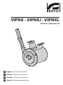
VIPNX - VIPNXJ - VIPNXL
Stainless steel wiper kit
EN English - Instructions manual
IT Italiano - Manuale di istruzioni
FR Français - Manuel d'instructions
DE Deutsch - Bedienungslanleitung
VIPNX - VIPNXJ - VIPNXL
EN
1 About this manual
3 Safety rules
Before installing and using this unit, please read this
manual carefully. Be sure to keep it handy for later
reference.
hh
1.1 Typographical conventions
DANGER!
High level hazard.
Risk of electric shock. Disconnect the
power supply before proceeding with any
operation, unless indicated otherwise.
gg
WARNING!
Medium level hazard.
This operation is very important for the
system to function properly. Please read
the procedure described very carefully and
carry it out as instructed.
hh
INFO
Description of system specifications.
We recommend reading this part carefully
in order to understand the subsequent
stages.
jj
The manufacturer declines all responsibility
for any damage caused by an improper use
of the appliances mentioned in this manual.
Furthermore, the manufacturer reserves
the right to modify its contents without any
prior notice. The documentation contained
in this manual has been collected with great
care, the manufacturer, however, cannot
take any liability for its use. The same thing
can be said for any person or company
involved in the creation and production of
this manual.
• The device must be installed only and exclusively
by qualified technical personnel.
• Before any technical work on the appliance,
disconnect the power supply.
• Do not use power supply cables that seem worn
or old.
• Never, under any circumstances, make any
changes or connections that are not shown in
this handbook: improper use of the appliance
can cause serious hazards, risking the safety of
personnel and of the installation.
2 Notes on copyright and
information on trademarks
• Use only original spare parts. Not original spare
parts could cause fire, electrical discharge or other
hazards.
The quoted names of products or companies are
trademarks or registered trademarks.
• Before proceeding with installation check the
supplied material to make sure it corresponds
to the order specification by examining the
identification labels ("4.2 Product markings", page 2).
1
EN - English - Instructions manual
Stainless steel wiper kit
EN - English - Instructions manual
4 Identification
4.1 Product description and type
designation
Wiper kit which can be directly installed on the
housing body. Wiperblade and enclosure constructed
from AISI 316 stainless steel. It includes the support
for the pump washing injector. Available in 24Vac and
230Vac versions, 7W max. Available for NXM, NXL,
NXJ series housings.
6 Assembling and
installing
Only specialised personnel should be
allowed to assemble and install the device.
hh
6.1 Installation
Before carrying out any operation
remember to disconnect the product from
the power supply.
hh
4.2 Product markings
See the label attached to the outside of the package.
For the version powered at 230Vac it is
necessary to insert a monopolar 1 0 switch
(open contact distance d>3 mm) upstream
of the appliance. This switch should be used
to disconnect the power supply before
carrying out any maintenance or opening
the appliance.
hh
5 Preparing the product
for use
Any change that is not expressly approved
by the manufacturer will invalidate the
guarantee.
hh
5.1 Contents and unpacking
When the product is delivered, make sure that the
package is intact and that there are no signs that it
has been dropped or scratched.
If there are obvious signs of damage, contact the
supplier immediately.
Keep the packaging in case you need to send the
product for repairs.
Check the contents to make sure they correspond
with the list of materials as below:
• Stainless steel wiper kit
• Instructions manual
5.2 Safely disposing of
packaging material
The packaging material can all be recycled. The
installer technician will be responsible for separating
the material for disposal, and in any case for
compliance with the legislation in force where the
device is to be used.
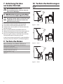
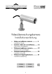
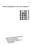
6.1.1 Glass window replacement (only
for NXM housing)
To install the kit on the NXM housing the standard
glass window should be replaced with the special
one supplied with the kit.
Remove the front flange (01) on the housing by
unscrewing the 4 screws (02).
Replace the standard glass (03) with the special glass
(04) and insert it in its special seating on the flange.
Reassemble the flange on the housing taking care
to insert the related seals (05) correctly in their
appropriate housing.
Fasten the front flange to the housing body by
tightening the 4 screws.
03
01
04
Bear in mind that if the material has to be returned
due to a fault, using the original packaging for its
transport is strongly recommended.
02
Fig. 01
2
05
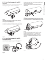
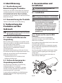
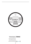
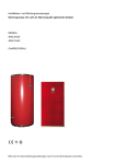
6.1.2 Installing the wiper kit on NXJ
housing
Tighten the band with a screwdriver, locking the
wiper body.
EN - English - Instructions manual
Position the wiper under the housing so that slots on
the body correspond with the fastening pins.
Position the wiper body (Fig. 3) by passing the band
round the housing body.
Fig. 05
Fig. 02
Assemble the wiper blade on the output shaft, fixing
it in the rest position on the left side of the glass front.
Fasten the wiper body to the housing by screwing
the nuts onto the fastening pins.
Assemble the wiper blade on the output shaft, fixing
it in the rest position on the left side of the glass front.
Fig. 06
Fig. 03
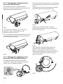
If necessary adjust the fastening band to set the
position of the wiper body so that it does not
interfere with the housing support. In this way
assembly is adaptable to the orientation of the
housing.
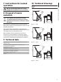
6.1.3 Installing the wiper kit on NXL
and NXM housing
Insert the open metal fastening band through the 2
slots on the wiper body as shown in the drawing.
Fig. 07
Fig. 04
3
EN - English - Instructions manual
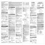
6.1.4 Installing the optional nozzle kit
(only for NXL housing)
Undo the nut (01) from the coupling, insert it into
the pipe (02) and insert the end of the pipe on the
nosecap (03).
01
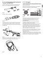
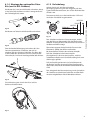
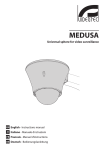
6.1.5 Wiring
Make sure the power supply voltage used is the
same as that shown on the plate on the back of the
appliance.
Make the electrical connections on the female 3+PE
connector as shown in the electrical diagram.
02
Fig. 08
Lock the nut to the coupling.
NEUTRAL
03
03
01
02
PHASE
PERM (01)
COM (02)
SW (03)
EARTH
SWITCH
Fig. 12
Power the wiper by connecting the phase to terminal
03 (SW) on the connector, neutral to terminal 02
(COM) on the connector and earth to the EARTH
terminal.
Fig. 09
Remove one of the 2 sunshield fastener screws (01)
located on the front of the housing. Slide the tube
(02) inside the clip (03) and use the screw (01) and
washer (02) to fasten in place.
02
04
03
Fig. 10
To adjust the jet direct the nozzle towards the glass of
the housing.
4
Keeping the external button pressed will cause
continuous operation (permanent) of the wiper.
Releasing the button will take the wiper blade back to
the rest position on the left of the housing window.
If a receiver is used, connect terminal 03 on the
connector to output SW on the receiver, 01 to PERM
and 02 to COM.
Connect the tube of the water supply system to the
spray nozzle of the wiper blade and fix it using the
plastic hose clamp supply for this purpose.
01
Fig. 11
Use an external button to connect the phase to
terminal 01 (PERM) on the connector.
R17
0
8 Disposal of waste
materials
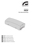
The values are in millimeters.
jj
This symbol mark and recycle system
are applied only to EU countries and not
applied to the countries in the other area of
the world.
nn
Please dispose of this equipment at your local
Community waste collection or Recycling centre.
104
191
VIPNX
2
Fig. 13
In the European Union there are separate collection
systems for used electrical and electronic products.
100
9 Technical data
Wiperblade and enclosure constructed from AISI 316
stainless steel
65
R20
This symbol means that electrical and electronic
equipment, at their end-of-life, should be disposed of
separately from your household waste.
100
258
Your product is designed and manufactured with
high quality materials and components which can be
recycled and reused.
EN - English - Instructions manual
Do not use the wiper when the outside
temperature is below 0°C or in case of ice.
hh
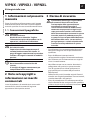
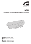
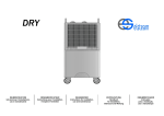
10 Technical drawings
226
7 Instructions for normal
operation
65
104
191
Fig. 14
VIPNXJ
4
Dimensions (ØxL): 100x169mm (3.9x6.6in), not
comprehensive of blade
IN 24Vac, consumption 7W max
270
IN 230Vac, consumption 7W max
R21
Connector 3+1 pins
Unit weight: 1.7kg / 3.7lb
IP66/67
100
65
104
191
Fig. 15
VIPNXL
5
VIPNX - VIPNXJ - VIPNXL
IT
IT - Italiano - Manuale di istruzioni
Kit tergicristallo inox
1 Informazioni sul presente
manuale
Prima di installare e utilizzare questa unità, leggere
attentamente questo manuale. Conservare questo
manuale a portata di mano come riferimento futuro.
1.1 Convenzioni tipografiche
PERICOLO!
Pericolosità elevata.
Rischio di scosse elettriche. Togliere
l'alimentazione prima di procedere con le
operazioni, salvo diversa indicazione.
gg
ATTENZIONE!
Pericolosità media.
L'operazione è molto importante per il
corretto funzionamento del sistema. Si
prega di leggere attentamente la procedura
indicata e di eseguirla secondo le modalità
previste.
hh
INFO
Descrizione delle caratteristiche del
sistema.
Si consiglia di leggere attentamente per
comprendere le fasi successive.
jj
2 Note sul copyright e
informazioni sui marchi
commerciali
I nomi di prodotto o di aziende citati sono marchi
commerciali o marchi commerciali registrati
appartenenti alle rispettive società.
1
3 Norme di sicurezza
Il produttore declina ogni responsabilità
per eventuali danni derivanti da un
uso improprio delle apparecchiature
menzionate in questo manuale. Si
riserva inoltre il diritto di modificarne il
contenuto senza preavviso. Ogni cura è
stata posta nella raccolta e nella verifica
della documentazione contenuta in questo
manuale, tuttavia il produttore non può
assumersi alcuna responsabilità derivante
dall'utilizzo della stessa. Lo stesso dicasi
per ogni persona o società coinvolta nella
creazione e nella produzione di questo
manuale.
hh
• L'installazione e la manutenzione del dispositivo
deve essere eseguita solo da personale tecnico
qualificato.
• Prima di effettuare interventi tecnici
sull'apparecchio togliere l'alimentazione elettrica.
• Non utilizzare cavi di alimentazione con segni di
usura o invecchiamento.
• Non effettuare per nessun motivo alterazioni o
collegamenti non previsti in questo manuale:
l'uso di apparecchi non idonei può portare a
gravi pericoli per la sicurezza del personale e
dell'impianto.
• Utilizzare solo parti di ricambio originali. Pezzi di
ricambio non originali potrebbero causare incendi,
scariche elettriche o altri pericoli.
• Prima di procedere con l'installazione controllare
che il materiale fornito corrisponda alle specifiche
richieste esaminando le etichette di marcatura ("4.2
Marcatura del prodotto", pagina 2).
4 Identificazione
4.1 Descrizione e designazione
del prodotto
4.2 Marcatura del prodotto
Vedere l’etichetta posta sull’esterno dell’imballo.
L'assemblaggio e l'installazione vanno
eseguiti solo da personale specializzato.
hh
6.1 Installazione
Prima di eseguire qualsiasi operazione
ricordarsi di togliere tensione al prodotto.
hh
Nella versione alimentata a 230Vac inserire
sulla linea di alimentazione, a monte
dell’apparecchiatura, un interruttore
generale unipolare 1 0 (distanza apertura
dei contatti d>3 mm). Tale interruttore
deve essere utilizzato come mezzo
di separazione dell’alimentazione
prima di eseguire qualsiasi operazione
di manutenzione o apertura
dell’apparecchiatura.
hh
5 Preparazione del
prodotto per l'utilizzo
Qualsiasi cambiamento non espressamente
approvato dal costruttore fa decadere la
garanzia.
hh
5.1 Contenuto e disimballaggio
Alla consegna del prodotto verificare che l'imballo
sia integro e non abbia segni evidenti di cadute o
abrasioni.
In caso di evidenti segni di danno all'imballo
contattare immediatamente il fornitore.
Conservare l'imballo nel caso sia necessario inviare il
prodotto in riparazione.
Controllare che il contenuto sia rispondente alla lista
del materiale sotto indicata:
• Kit tergicristallo inox
• Manuale di istruzioni
5.2 Smaltimento in sicurezza dei
materiali di imballaggio
I materiali d'imballo sono costituiti interamente da
materiale riciclabile. Sarà cura del tecnico installatore
smaltirli secondo le modalità di raccolta differenziata
o comunque secondo le norme vigenti nel Paese di
utilizzo.
6.1.1 Sostituzione del vetro (solo per
custodia NXM)
Per installare il kit sulla custodia NXM è necessario
sostituire il vetro standard con uno speciale in
dotazione al kit.
Smontare la flangia anteriore (01) della custodia
svitando le 4 viti (02).
Sostituire il vetro standard (03) con il vetro speciale
(04) inserendolo nell’apposita sede sulla flangia.
Rimontare la flangia sulla custodia facendo
attenzione che le relative guarnizioni (05) siano
inserite correttamente nelle apposite sedi.
Fissare la flangia anteriore al corpo custodia serrando
le 4 viti.
03
01
Si ricorda comunque che in caso di ritorno di
materiale con malfunzionamenti è consigliato
l'imballaggio originale per il trasporto.
04
02
05
Fig. 01
2
IT - Italiano - Manuale di istruzioni
Kit tergicristallo installabile direttamente sul corpo
custodia. Spazzola e corpo in acciaio. Integra il
supporto per l’iniettore di lavaggio proveniente dalla
pompa. Disponibile nelle versioni 24Vac e 230Vac,
7W max. Disponibile per le custodie della serie NXM,
NXL e NXJ.
6 Assemblaggio e
installazione
6.1.2 Installazione del kit tergicristallo
su custodia NXJ
IT - Italiano - Manuale di istruzioni
Posizionare il tergicristallo sotto alla custodia
mettendo le asole del corpo in corrispondenza dei
perni di fissaggio.
Posizionare il corpo tergicristallo facendo passare la
fascetta attorno al corpo della custodia.
Serrare la fascetta con un cacciavite bloccando il
corpo tergicristallo.
Fig. 05
Fig. 02
Montare la spazzola del tergicristallo sull’albero
d’uscita fissandola nella posizione di riposo sul lato
sinistro del vetro frontale.
Fissare il corpo tergicristallo alla custodia avvitando i
dadi sui perni di fissaggio.
Montare la spazzola del tergicristallo sull’albero
d’uscita fissandola nella posizione di riposo sul lato
sinistro del vetro frontale.
Fig. 06
Agendo sulla fascetta di fissaggio regolare
eventualmente la posizione del corpo del
tergicristallo in modo che questo non interferisca con
il supporto della custodia. Il montaggio risulta così
flessibile a seconda dell’orientamento della custodia.
Fig. 03
6.1.3 Installazione del kit tergicristallo
su custodia NXL e NXM
Inserire la fascetta metallica di fissaggio, aperta,
attraverso le 2 asole del corpo del tergicristallo come
mostrato in figura.
Fig. 07
Fig. 04
3
6.1.4 Installazione kit ugello opzionale
(solo per custodia NXL)
Svitare il dado (01) dal raccordo, inserirlo nel tubo
(02) e inserire l’estremità del tubo sull’ogiva (03).
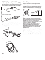
6.1.5 Cablaggio
Prestare attenzione che la tensione di alimentazione
usata sia quella indicata sulla targhetta posta sul retro
dell’apparecchiatura.
01
03
NEUTRAL
03
PHASE
02
Fig. 08
Serrare il dado al raccordo.
01
02
IT - Italiano - Manuale di istruzioni
Effettuare le connessioni elettriche sul connettore
femmina 3+PE come da schema elettrico.
PERM (01)
COM (02)
SW (03)
EARTH
SWITCH
Fig. 12
Alimentare il tergicristallo collegando la fase al
morsetto 03 (SW) del connettore, il neutro al
morsetto 02 (COM) del connettore e la terra al
morsetto EARTH.
Fig. 09
Svitare una delle 2 viti di fissaggio (01) del tettuccio
sulla parte anteriore della custodia. Inserire il tubo
(02) nella fascetta (03) e fissare il tutto con vite (01) e
rondella (04).
02
01
04
03
Collegare tramite un pulsante esterno la fase al
morsetto 01 (PERM) del connettore.
Mantenendo premuto il pulsante esterno si otterrà
un funzionamento continuo (permanente) del
tergicristallo. Rilasciando il pulsante la spazzola del
tergicristallo si porterà nella posizione di riposo al
lato sinistro del vetro della custodia.
Nel caso si utilizzi un ricevitore collegare il morsetto
03 del connettore all’uscita SW del ricevitore, 01 a
PERM e 02 a COM.
Collegare il tubo dell’impianto alimentazione acqua
all’ugello spruzzatore della spazzola del tergicristallo
e fissarlo con la fascetta plastica in dotazione.
Fig. 10
Per regolare il getto orientare l'ugello verso il vetro
della custodia e collegare il tubo di mandata.
Fig. 11
4
Questo simbolo e il sistema di riciclaggio
sono validi solo nei paesi dell'EU e non
trovano applicazione in altri paesi del
mondo.
nn
Il vostro prodotto è stato costruito da materiali e
componenti di alta qualità, che sono riutilizzabili o
riciclabili.
100
104
191
Fig. 13
VIPNX
258
R20
2
Prodotti elettrici ed elettronici che portano questo
simbolo alla fine dell'uso devono essere smaltiti
separatamente dai rifiuti casalinghi.
Vi preghiamo di smaltire questo apparecchio in un
Centro di raccolta o in un'Ecostazione.
65
Nell'Unione Europea esistono sistemi di raccolta
differenziata per prodotti elettrici ed elettronici.
100
9 Dati tecnici
65
Spazzola e corpo in acciaio Inox AISI 316
Dimensioni (ØxL): 100x169mm, non comprensivo di
spazzola
104
191
Fig. 14
VIPNXJ
Connettore 3+1 contatti
R21
4
IN 230Vac, consumo 7W max
IN 24Vac, consumo 7W max
Peso unitario: 1.7kg
270
IT - Italiano - Manuale di istruzioni
8 Smaltimento dei rifiuti
I valori espressi sono in millimetri.
jj
R17
0
Non utilizzare il tergicristallo quando la
temperatura esterna è inferiore agli 0°C o in
presenza di ghiaccio.
hh
10 Disegni tecnici
226
7 Istruzioni di
funzionamento ordinario
IP66/67
100
65
104
191
Fig. 15
5
VIPNXL
VIPNX - VIPNXJ - VIPNXL
FR
Kit essuie-glace inox
1 À propos de ce mode
d’emploi
1.1 Conventions typographiques
DANGER!
Risque élevé.
Risque de choc électrique. Sauf indication
contraire, sectionner l’alimentation avant
de procéder à toute opération.
gg
ATTENTION!
Risque moyen.
Opération extrêmement importante en vue
d’un fonctionnement correct du système;
lire avec attention les opérations indiquées
et s’y conformer rigoureusement.
hh
REMARQUE
Description des caractéristiques du
système.
Il est conseillé de procéder à une
lecture attentive pour une meilleure
compréhension des phases suivantes.
jj
2 Notes sur le copyright
et informations sur les
marques de commerce
Les noms de produit ou de sociétés cités sont des
marques de commerce ou des marques de commerce
enregistrées.
Le producteur décline toute responsabilité
pour les dommages éventuels dus à une
utilisation non appropriée des appareils
mentionnés dans ce manuel. On réserve
en outre le droit d’en modifier le contenu
sans préavis. La documentation contenue
dans ce manuel a été rassemblée et vérifiée
avec le plus grand soin, cependant, le
producteur ne peut pas s’assumer aucune
responsabilité dérivante de l’emploi de
celle là. La même chose vaut pour chaque
personne ou société impliquées dans la
création et la production de ce manuel.
hh
• L’installation et l’entretien du dispositif doivent
être exclusivement être effectués par un personnel
technique qualifié.
• Sectionner l’alimentation électrique avant toute
intervention technique sur l’appareil.
• Ne pas utiliser de câbles d’alimentation usés ou
endommagés.
• Ne procéder sous aucun prétexte à des
modifications ou des connexions non prévues
dans ce manuel: l’utilisation d’appareils non
adéquats peut comporter des dangers graves pour
la sécurité du personnel et de l’installation.
• Utiliser uniquement des pièces de rechange
d’origine. Les pièces non d’origine peuvent être
source d’incendies, de choc électrique ou autres.
• Avant de procéder à l’installation, contrôler que
le matériel fourni correspond à la commande
et examiner les étiquettes de marquage ("4.2
Marquage du produit", page 2).
1
FR - Français - Manuel d'instructions
Avant d’installer et d’utiliser cet appareil, veuillez
lire attentivement ce mode d’emploi. Conservez-le à
portée de main pour pouvoir vous y reporter en cas
de besoin.
3 Normes de securité
4 Identification
FR - Français - Manuel d'instructions
4.1 Description et désignation
du produit
Kit essuie-glace, à installer directement sur le corps
du caisson, comprenant le gliceur de lavage qui vient
de la pompe du lave glace. Balai et corps en acier
Inox AISI 316. Disponible dans les versions 24Vac et
230Vac, 7W max. Disponible pour les caissons de la
série NXM, NXL et NXJ.
4.2 Marquage du produit
Voir l’étiquette sur l’extérieur de l’emballage.
6 Assemblage et
installation
L’assemblage et l’installation doivent
exclusivement être effectués par un
personnel spécialisé.
hh
6.1 Installation
Avant toute intervention, mettre le produit
hors tension.
hh
Sur le modèle avec alimentation à 230Vac,
insérer un interrupteur général unipolaire
1 0 sur la ligne d'alimentation en amont de
l'appareil (distance ouverture des contacts
d>3 mm). Cet interrupteur doit être utilisé
pour séparer l'alimentation avant toute
opération d'entretien et toute ouverture de
l'appareil.
hh
5 Préparation du produit
en vue de l’utilisation
Toute modification non approuvée
expressément par le fabricant entraînera
l’annulation de la garantie.
hh
5.1 Contenu et déballage
Lors de la livraison du produit, vérifier que
l’emballage est en bon état et l’absence de tout signe
évident de chute ou d’abrasion.
En cas de dommages évidents, contacter
immédiatement le fournisseur.
Conserver l’emballage en cas de nécessité
d’expédition du produit pour réparation.
Contrôler que le contenu correspond à la liste
matériel indiquée ci-dessous:
• Kit essuie-glace inox
• Manuel d'instructions
5.2 Élimination sans danger des
matériaux d’emballage
Le matériel d’emballage est entièrement composé
de matériaux recyclables. Le technicien chargé de
l’installation est tenu de l’éliminer conformément aux
dispositions en matière de collecte sélective et selon
les normes en vigueur dans le pays d’utilisation.
6.1.1 Remplacement de la vitre
(seulement pour caisson NXM)
Pour installer le kit sur le caisson NXM, il est
nécessaire de remplacer la vitre standard par la vitre
spécial livré avec le kit.
Démonter la bride avant (01) du caisson en dévissant
les 4 vis (02)
Remplacer la vitre standard (03) par la vitre spécial
(04) en l'installant dans le logement prévu sur la
bride.
Remonter la bride sur le caisson en ayant soin que les
garnitures (05) soient correctement installées dans
leurs logements.
Fixer la bride avant au corps du caisson et serrer les
4 vis.
03
01
En cas de dysfonctionnement et de retour de
matériel, il est conseillé d’utiliser l’emballage original
pour le transport.
04
02
Fig. 01
2
05
6.1.2 Installation du kit essuie-glace sur
caisson NXJ
Positionner l'essuie-glace sous le caisson en faisant
correspondre les fentes du corps essuie-glace avec
les goujons de fixation.
Positionner le corps essuie-glace (Fig. 3) en faisant
passer le collier autour du corps du caisson.
Serrer le collier au moyen d'un tournevis et bloquer le
corps essuie-glace.
FR - Français - Manuel d'instructions
Fig. 05
Fig. 02
Monter le balai de l'essuie-glace sur l'arbre en sortie
en le fixant en position de repos sur le côté gauche
du verre frontal.
Fixer le corps essuie-glace au caisson en vissant les
écrous sur les goujons d'assemblage.
Monter le balai de l'essuie-glace sur l'arbre en sortie
en le fixant en position de repos sur le côté gauche
du verre frontal.
Fig. 06
Au moyen du collier de fixation, régler si nécessaire la
position du corps de l'essuie-glace de façon à ce que
ce dernier ne se trouve pas en contact avec le support
du caisson. Ce montage de type flexible s'adapte à
l'orientation du caisson.
Fig. 03
6.1.3 Installation du kit essuie-glaces
sur caisson NXL et NXM
Mettre en place le collier métallique de fixation,
ouvert, à travers les 2 fentes du corps essuie-glace,
comme indiqué à la figure.
Fig. 07
Fig. 04
3
6.1.4 Installation du kit de la buse
optional (seulement pour caisson NXL)
Desserrer l’écrou (01) du raccord, l’insérer dans le tube
(02) et introduire l’extrémité du tube sur l’ogive (03).
6.1.5 Câblage
Contrôler que la tension d'alimentation utilisée
corresponde à celle indiquée sur la plaque fixée à
l'arrière de l'appareil.
FR - Français - Manuel d'instructions
Procéder aux connexions électriques du connecteur
femelle 3+PE conformément au schéma électrique.
01
03
NEUTRAL
03
PHASE
02
Fig. 08
Serrer l’écrou au raccord
01
02
PERM (01)
COM (02)
SW (03)
EARTH
SWITCH
Fig. 12
Mettre l'essuie-glace sous tension en connectant la
phase à la borne 03 (SW) du connecteur, le neutre à la
borne 02 (COM), et la terre à la borne EARTH.
Fig. 09
Desserrer l'une des 2 vis de fixation (01) de l'auvent
placées à l'avant du caisson. Introduire le tube (02)
dans le collier (03) et fixer le tout avec vis (01) et
rondelle (04).
02
04
03
Fig. 10
Pour calibrer le jet orienter la buse vers la vitre du
caisson.
4
Maintenir le poussoir externe enfoncé pour un
fonctionnement de l'essuie-glace en continu.
Relâcher le poussoir pour placer le balai de l'essuieglace en position de repos sur le côté gauche du
verre du caisson.
En cas d'utilisation d'un récepteur, brancher la borne
03 du connecteur à la sortie SW du récepteur, la 01 à
PERM et la 02 à COM.
Connecter le tube de l’alimentation de l’eau à la
busette pour l’arrosage de la brosse de l’essuie-glace
et le fixer en utilisant le collier en plastique fourni.
01
Fig. 11
Au moyen d'un poussoir externe, connecter la phase
à la borne 01 (PERM) du connecteur.
Ce symbole et le système de recyclage ne
sont appliqués que dans les pays UE et non
dans les autres pays du monde.
nn
Votre produit est conçu et fabriqué avec des matèriels
et des composants de qualité supérieure qui peuvent
être recyclés et réutilisés.
100
104
191
Fig. 13
VIPNX
258
R20
2
Ce symbole signifie que les équipements électriques
et électroniques en fin de vie doivent être éliminés
séparément des ordures ménagères.
Nous vous prions donc de confier cet équipement à
votre Centre local de collecte ou Recyclage.
65
FR - Français - Manuel d'instructions
8 Élimination des déchets
Les valeurs sont entendues en millimètres.
jj
R17
0
Ne pas utiliser l’essuie-glace lorsque la
température extérieure est inférieure à 0°C
ou en cas de glace.
hh
10 Dessins techniques
226
7 Instructions de
fonctionnement courant
Dans l’Union Européenne, il existe des systèmes
sélectifs de collecte pour les produits électriques et
électroniques usagés.
100
9 Données techniques
65
Balai et corps en acier Inox AISI 316
Dimensions (ØxL): 100x169mm, sans balai
104
191
Fig. 14
VIPNXJ
Connecteur 3+1 contacts
IN 230Vac, consommation 7W max
R21
4
IN 24Vac, consommation 7W max
IP66/67
270
Poids net: 1.7kg
100
65
104
191
Fig. 15
VIPNXL
5
VIPNX - VIPNXJ - VIPNXL
DE
DE - Deutsch - Bedienungslanleitung
Scheibenwischer-Kit aus rostfreiem Stahl
1 Allgemeines
3 Sicherheitsnormen
Lesen Sie bitte vor dem Installieren und dem
Verwenden dieses Gerätes die Bedienungsanleitung
sorgfältig durch. Bewahren Sie sie zum späteren
Nachschlagen auf.
hh
1.1 Schreibweisen
GEFAHR!
Erhöhte Gefährdung.
Stromschlaggefahr. Falls nichts anderes
angegeben, unterbrechen Sie die
Stromversorgung, bevor die beschriebenen
Arbeiten durchgeführt werden.
gg
ACHTUNG!
Mittlere Gefährdung.
Der genannte Vorgang hat große
Bedeutung für den einwandfreien Betrieb
des Systems: es wird gebeten, sich die
Verfahrensweise anzulesen und zu
befolgen.
hh
ANMERKUNG
Beschreibung der Systemmerkmale.
Eine sorgfältige Lektüre wird empfohlen,
um das Verständnis der folgenden Phasen
zu gewährleisten.
jj
2 Anmerkungen
zum Copyright und
Informationen zu den
Handelsmarken
Die angeführten Produkt- oder Firmennamen sind
Handelsmarken oder eingetragene Handelsmarken.
1
Der Hersteller lehnt jede Haftung für
eventuelle Schäden ab, die aufgrund
unsachgemäßer Anwendung der in diesem
Handbuch erwähnten Geräte entstanden
ist. Ferner behält er sich das Recht vor, den
Inhalt ohne Vorkündigung abzuändern.
Die Dokumentation in diesem Handbuch
wurde sorgfältig ausgeführt und überprüft,
dennoch kann der Hersteller keine Haftung
für die Verwendung übernehmen. Dasselbe
gilt für jede Person oder Gesellschaft, die
bei der Schaffung oder Produktion von
diesem Handbuch miteinbezogen ist.
• Die Installation und Wartung der Vorrichtung ist
technischen Fachleuten vorbehalten.
• Vor technischen Eingriffen am Gerät muss die
Stromversorgung unterbrochen werden.
• Es dürfen keine Versorgungskabel mit Verschleißoder Alterungsspuren verwendet werden.
• Unter keinen Umständen dürfen Veränderungen
oder Anschlüsse vorgenommen werden, die
in diesem Handbuch nicht genannt sind: Der
Gebrauch ungeeigneten Geräts kann die Sicherheit
des Personals und der Anlage schwer gefährden.
• Es dürfen nur Original-Ersatzteile verwendet
werden. Nicht originale Ersatzteile können zu
Bränden, elektrischen Entladungen oder anderen
Gefahren führen.
• Vor der Installation ist anhand des
Kennzeichnungsschildes nachzuprüfen, ob das
gelieferte Material die gewünschten Eigenschaften
aufweist ("4.2 Kennzeichnung des Produkts", Seite 2).
4 Identifizierung
4.1 Beschreibung und
Bezeichnung des Produktes
Wischer-Kit, der direkt auf den Körper des Gehäuses
installiert werden kann. Der Wischer beinhaltet die
Waschspritzdüse der Pumpe. Bürste und Körper
aus rostfreiem Stahl AISI 316. 24Vac- und 230VacAusführung, 7W max, lieferbar. Für Gehäuse der Serie
NXM, NXL und NXJ.
Siehe das Schild außen auf der Verpackung.
Zusammenbau und Installation sind
Fachleuten vorbehalten.
hh
6.1 Installation
Vor jedweder Tätigkeit ist die Spannungsversorgung des Produktes zu unterbrechen.
hh
In der mit 230Vac gespeisten
Ausführung muß dem Gerät auf der
Versorgungsleitung ein einpoliger
Hauptschalter 1 0 vorgeschaltet werden
(Unterbrecherkontaktabstand d>3 mm).
Dieser Schalter ist als Trennvorrichtung
zum Abnehmen der Stromversorgung
einzusetzen, bevor Wartungsarbeiten
durchgeführt werden oder das Gerät
geöffnet wird.
hh
5 Vorbereitung des
Produktes auf den
Gebrauch
Jede vom Hersteller nicht ausdrücklich
genehmigte Veränderung führt zum Verfall
der Gewährleistungsrechte.
hh
5.1 Inhalt und Entfernen der
Verpackung
Bei der Lieferung des Produktes ist zu prüfen, ob die
Verpackung intakt ist oder offensichtliche Anzeichen
von Stürzen oder Abrieb aufweist.
Bei offensichtlichen Schadensspuren an der
Verpackung muss umgehend der Lieferant
verständigt werden.
Bewahren Sie die Verpackung auf für den Fall, dass
das Produkt zur Reparatur eingesendet werden muss.
Prüfen Sie, ob der Inhalt mit der nachstehenden
Materialliste übereinstimmt:
• Scheibenwischer-Kit aus rostfreiem Stahl
DE - Deutsch - Bedienungslanleitung
4.2 Kennzeichnung des Produkts
6 Zusammenbau und
Installation
6.1.1 Ersatz von Glas (nur für NXM
Gehäuse)
Das Standard-Glas durch ein mitgeliefertes
Spezialglas ersetzen, um das Kit auf dem NXM
Gehäuse zu installieren.
Den vorderen Gehäuseflansch (01) durch Lösen der 4
Schrauben (02) entfernen.
Das Normalglas (03) durch das Spezialglas ersetzen
(04). Es wird in die vorgesehene Aufnahmestelle am
Flansch eingesetzt.
Den Flansch wieder am Gehäuse anbringen. Achten
Sie darauf, daß die zugehörigen Dichtungen (05)
richtig sitzen.
Den vorderen Flansch mit den 4 Schrauben am
Gehäusekorpus befestigen.
• Bedienungslanleitungen
5.2 Sichere Entsorgung der
Verpackungsmaterialien
03
01
Die Verpackungsmaterialien sind vollständig
wiederverwertbar. Es ist Sache des
Installationstechnikers, sie getrennt, auf jeden
Fall aber nach den geltenden Vorschriften des
Anwendungslandes zu entsorgen.
Es wird nochmals empfohlen, mit Fehlfunktionen
behaftetes Material in der Originalverpackung
zurückzusenden.
04
02
05
Fig. 01
2
6.1.2 Montage des ScheibenwischerKits an das NXJ Gehäuse
DE - Deutsch - Bedienungslanleitung
Den Scheibenwischer so unter dem Gehäuse
positionieren, daß die Langlöcher im Korpus mit den
Befestigungsstiften übereinstimmen.
Den Korpus der Waschanlage (Fig. 3) so positionieren,
daß die Befestigungsschelle um den Gehäusekorpus
reicht.
Die Schelle mit einem Schraubendreher festziehen,
damit der Korpus der Waschanlage festsitzt.
Fig. 05
Fig. 02
Der Scheibenwischerkorpus wird am Gehäuse
befestigt, in dem man die Muttern an die
Befestigungsstiften schraubt.
Die Bürste des Scheibenwischers so auf die
Abtriebswelle montieren, daß sie in Ruhestellung
links vom Frontglas sitzt.
Nun die Scheibenwischerbürste auf die Abtriebswelle
montieren, indem man sie in der Ruhestellung links
vom vorderen Glas befestigt.
Fig. 06
Fig. 03
Durch Verstellen der Befestigungsschelle wird
die Position des Scheibenwischerkorpus bei
Bedarf so nachreguliert, daß dieser nicht mit der
Gehäusehalterung kollidiert. Die Montage läßt sich
auf diese Weise flexibel an die Ausrichtung des
Gehäuses anpassen.
6.1.3 Montage des ScheibenwischerKits an das NXL und NXM Gehäuse
Die geöffnete Metallschelle durch die beiden
Langlöcher im Korpus der Scheibenwaschanlage
führen, wie in der Abbildung gezeigt.
Fig. 07
Fig. 04
3
6.1.4 Montage des optionellen DüseKits (nur für NXL Gehäuse)
Die Mutter (01) vom Anschlußstück schrauben, dieses
in das Rohr (02) einführen und das Leitungsende auf
den Dichtkegel (03) setzen.
6.1.5 Verkabelung
Achten Sie darauf, daß die vorhandene
Versorgungsspannung mit den Angaben auf dem
Typenschild übereinstimmt, das auf der Rückseite des
Gerätes sitzt.
Die Stromanschlüsse an die Steckbuchse 3-PE wird
nach dem Schaltbild vorgenommen.
01
03
NEUTRAL
03
PHASE
02
Die Mutter auf dem Anschlußstück festschrauben.
01
02
PERM (01)
COM (02)
SW (03)
EARTH
Fig. 12
Den Scheibenwischer mit Strom versorgen, indem
man die Phase an Klemme 03 (SW) der Buchse, den
Nulleiter an Klemme 02 (COM) der Buchse und Erde an
die Klemme EARTH anlegt.
Fig. 09
Eine der beiden Befestigungsschrauben (01) des
Sonnenschutzdaches ausdrehen, die sich im
vorderen Teil des Gehäuses befinden. Das Rohr (02)
in die Schelle (03) einführen und das Ganze mit der
Schraube (01) und einer Unterlegscheibe (04) fixieren.
02
01
04
03
Über einen externen Knopf wird die Phase mit der
Klemme 01 (PERM) der Buchse verbunden.
Bei dauerhaftem Drücken des externen Knopfes
läuft der Scheibenwischer kontinuierlich
(durchgehend). Läßt man den Knopf los, wird die
Scheibenwischerbürste in ihre Ruhestellung links vom
Gehäuseglas geführt.
Falls ein Empfänger benutzt wird, wird Klemme 03
der Buchse mit dem Ausgang SW des Empfangsteils
verbunden, Klemme 01 mit PERM und Klemme 02 mit
COM.
Den Anlagerohr der Wasserspeisung an der Spritzdüse
der Scheiben-wischerbürste verbinden und den Rohr
mit dem mitgelieferten Plastik-Bändchen fixieren.
Fig. 10
Zur Kalibrierung des Strahls die Düse auf die
Gehäusescheibe richten.
Fig. 11
4
DE - Deutsch - Bedienungslanleitung
Fig. 08
SWITCH
Dieses Symbol und das entsprechende
Recycling-System gelten nur für EULänder
und finden in den anderen Ländern der
Welt keine Anwendung.
nn
104
191
VIPNX
2
Fig. 13
R20
Dieses Symbol bedeutet, daß elektrische und
elektronische Geräte am Ende ihrer Nutzungsdauer
von Hausmüll getrennt entsorgt werden sollen.
65
258
Ihr Produkt wurde entworfen und hergestellt
mit qualitativ hochwertigen Materialien und
Komponenten, die recycelt und wiederverwendet
werden können.
100
Bitte entsorgen Sie dieses Gerät bei Ihrer örtlichen
Sammelstelle oder im Recycling Centre.
In der Europäischen Union gibt es unterschiedliche
Sammelsysteme für Elektrik- und Elektronikgeräte.
100
65
9 Technische Daten
Bürste und Körper aus rostfreiem Stahl AISI 316
104
191
Fig. 14
VIPNXJ
Abmessungen (ØxL): 100x169mm, ohne Bürste
Verbinder 3+1 Kontakte
R21
4
IN 230Vac, Verbrauch 7W max
IN 24Vac, Verbrauch 7W max
Einheitsgewicht: 1.7kg
270
DE - Deutsch - Bedienungslanleitung
8 Müllentsorgungsstellen
Maßangabe in Millimeter.
jj
R17
0
Der Scheibenwischer ist bei
Aussentemperaturen unter 0°C oder bei
Glas nicht zu betätigen
hh
10 Technische Zeichnungen
226
7 Anleitung für den
normalen Betrieb
IP66/67
100
65
104
191
Fig. 15
5
VIPNXL
VIDEOTEC S.p.A.
www.videotec.com
Printed in Italy
MNVKVIPNX_1115