1
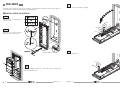
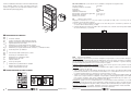
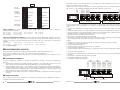
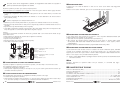
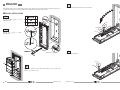
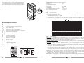
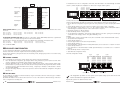
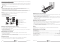
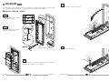
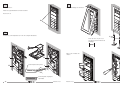
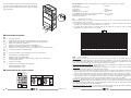
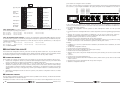
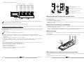
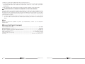
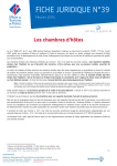
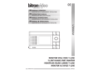
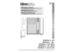
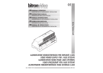
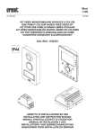
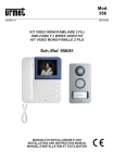
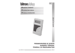
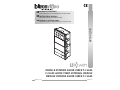
MANUALE ISTRUZIONI
CARATTERISTICHE DI FUNZIONAMENTO E INSTALLAZIONE
INSTRUCTIONS MANUAL
OPERATING AND INSTALLATION FEATURES
MANUEL D’INSTRUCTIONS
AV1001/08
CARATERISTIQUES DE FONCTIONNEMENT ET INSTALLATION
MODULO ESTERNO AUDIO VIDEO T-CLASS
T-CLASS AUDIO VIDEO EXTERNAL MODULE
MODULE EXTERNE AUDIO VIDÉO T-CLASS
DS901001-007
LBT 90321
ITALIANO
4
1
Il modulo esterno audio video AV1001/08 è dedicato al sistema B-Twin. Realizzato su meccanica T-Class a 2
moduli prevede 2 tasti di chiamata e telecamera grandangolare.
Ribaltare il telaio ed effettuare i cablaggi.
INSTALLAZIONE PULSANTIERA
1
1
Montare il telaio portamoduli sulla
scatola incasso.
2
A
1
B
1
C
2
1
B
Rimuovere le colonnine presenti
all’interno della scatola incasso.
A
A
5
1
Cerniera metallica
Regolare i livelli fonici.
II
3
1
Montare i moduli sul telaio con i tasti sulla destra procedendo dal
basso all’alto (da I a II).
I
2
DS901001-007
DS901001-007
3
6
1
8
1
Chiudere il telaio.
Montare la cornice sul telaio.
Regolare la corretta perpendicolarità della pulsantiera.
Avvitare le viti A.
A
7
1
Montare i cartellini portanome sul frontale estraibile.
C
Serrare le viti a brugola ø 2,5 mm
nella parte inferiore della cornice.
ø 2,5
Smontaggio dei moduli
dal telaio.
I
II
II
Cartellino trasparente
I
BIANCHI
Cartellino serigrafato stampabile
BIANCHI
4
DS901001-007
DS901001-007
5
Funzione “feedback di chiamata”: al momento della chiamata
da un qualsiasi modulo con tasti, viene emesso dal posto
esterno un segnale visivo che testimonia l’effettivo inoltro
della chiamata (led lampeggiante).
Valori di default: tutti i posti esterni escono di fabbrica configurati nel seguente modo:
Tipo di postazione:
principale
Indirizzo postazione secondaria:
0
Apriporta:
segreto
Interruzione:
Non abilitata
Illuminatori telecamera:
attivi
Rotary tempo comunicazione garantita: 30 sec. (pos 3)
Rotary tempo apriporta:
1 sec. (pos 0)
Numero posto esterno:
0
GV:
numero di posto esterno
Impostare un numero da 0 a 3 se il posto esterno è principale (v. FUN) o da 0 a 31 se il posto esterno è
secondario secondo la figura seguente.
• Non ci devono essere 2 postazioni principali con lo stesso GV, possono coesistere 2 postazioni secondarie
con stesso GV ma numero diverso (v. FUN).
• Il numero GV del posto esterno secondario deve coincidere con il codice di colonna impostato nell’adattatore
di colonna AV1001/05, se presente.
GV
ON
DESCRIZIONE DEI MORSETTI
BUS
BUS
AP+
APA[V
S
B[V
S
AD
AD
AP2
AP2
SW
SW
0
TA
SAP
L
L
+
}
Linea Bus entrante
}
}
Comando per commutatore video
Riferimento per commutatore video
Riferimento per TA e SAP
Pulsante androne
Sensore porta aperta
}
Negativo di alimentazione locale
Positivo di alimentazione locale
CONFIGURAZIONE DEI POSTI ESTERNI
78
4 56
78
DIP
1 2 3 4 5
ON
DIP
23
9 01
4 56
6
FUN
ON
23
9 01
1 2 3 4 5
CONV
TIME
GV
ON
ON
=
DIP
ON
DIP
ON
DIP
ON
DIP
ON
DIP
1 2 3 4 5
1 2 3 4 5
1 2 3 4 5
1 2 3 4 5
1 2 3 4 5
GV=1
GV=2
GV=3
GV=4
GV=5
GV=6
DIP
ON
DIP
ON
DIP
ON
DIP
ON
DIP
ON
DIP
ON
DIP
1 2 3 4 5
1 2 3 4 5
1 2 3 4 5
1 2 3 4 5
1 2 3 4 5
1 2 3 4 5
1 2 3 4 5
GV=8
GV=9
GV=10
GV=11
GV=12
GV=13
GV=14
DIP
ON
DIP
ON
DIP
ON
DIP
ON
DIP
ON
DIP
ON
DIP
1 2 3 4 5
1 2 3 4 5
1 2 3 4 5
1 2 3 4 5
1 2 3 4 5
1 2 3 4 5
1 2 3 4 5
GV=16
GV=17
GV=18
GV=19
GV=20
GV=21
GV=22
DIP
ON
DIP
ON
DIP
ON
DIP
ON
DIP
ON
DIP
ON
DIP
ON
DIP
1 2 3 4 5
GV=7
ON
DIP
1 2 3 4 5
GV=15
ON
DIP
1 2 3 4 5
GV=23
ON
DIP
1 2 3 4 5
1 2 3 4 5
1 2 3 4 5
1 2 3 4 5
1 2 3 4 5
1 2 3 4 5
1 2 3 4 5
1 2 3 4 5
GV=24
GV=25
GV=26
GV=27
GV=28
GV=29
GV=30
GV=31
FUN:
impostazioni ausiliarie
Tipo di postazione: il posto esterno può essere configurato come principale o come secondario. Dal posto esterno
principale è possibile chiamare tutti gli utenti dell’impianto, dal posto esterno secondario è possibile chiamare
solo gli utenti della colonna di appartenenza. L’utente che riceve la chiamata è in grado di distinguerne la
provenienza dalla temporizzazione con cui viene emesso lo squillo.
Indirizzo postazione di chiamata secondaria: in una stessa colonna possono essere presenti 2 postazioni di
chiamata secondarie che devono avere numero diverso.
Apriporta: l’elettroserratura può essere gestita in modalità ‘sotto segreto’ o ‘libero’. Il comportamento del posto
esterno è il seguente nei due casi:
• ‘Sotto segreto’: la pressione del pulsante apriporta di un posto interno può attivare l’elettoserratura della
postazione di chiamata solo se ha ricevuto una chiamata o è in conversazione fonica con essa o anche se,
in seguito ad autoinserzione, è comunque in connessione video con essa.
• ‘Libero’: la pressione del pulsante apriporta di un posto interno può attivare l’elettroserratura del posto
esterno solo se il posto esterno è configurato come principale o l’utente appartiene alla colonna dello stesso
posto esterno secondario. Tale colonna è definita dalla impostazione del GV del posto esterno secondario.
La prestazione è usata tipicamente sulle postazioni secondarie.
Interruzione: quando è in corso un’autoinserzione o una conversazione intercomunicante o la consultazione
della segreteria videocitofonica la colonna interessata o l’intero sistema è in stato di occupato che può essere,
a seconda della configurazione di questo switch, interrotto da una chiamata dal posto esterno oppure no.
Illuminatori telecamera: è possibile disattivare l’accensione degli illuminatori della telecamera laddove
l’illuminazione notturna dell’ambiente circostante sia ritenuta sufficiente.
Alimentazione per illuminazione cartellini
DOOR
TIME
ON
1 2 3 4 5
ON
Azionamento elettroserratura passo carraio
DIP
GV=0
ON
Uscita dispositivo per audiolesi
ON
1 2 3 4 5
ON
Positivo azionamento elettroserratura pedonale
Negativo azionamento elettroserratura pedonale
Segnale telecamera di controllo
Riferimento per segnale telecamera di controllo
Segnale telecamera di controllo 2 / commutatore video
Riferimento per segnale telecamera di controllo 2 / commutatore video
DIP
=
DS901001-007
DS901001-007
7
Secondaria
1 2 3 4 5
DIP
ON
DIP
Secondaria 0
DIP
1 2 3 4 5
ON
Apriporta
libero
DIP
Interruzione
ON
DIP
1 2 3 4 5
ON
DIP
Abilitata
1 2 3 4 5
ON
DIP
1 2 3 4 5
Apriporta
sotto segreto
C1 2 3 4
Non abilitata
OUTPUT
1 2 3 4 5
Illuminatori
telecamera
disattivi
ON
DIP
1 2 3 4 5
Illuminatori
telecamera
attivi
TEMPO APRIPORTA La posizione del rotary switch (DOOR TIME) determina il tempo di attivazione
dell’elettroserratura pedonale.
Pos. 0 = 1 sec.
Pos. 1 = 10 sec.
Pos. 2 = 20 sec.
Pos. 3 = 30 sec.
Pos. 4 = 40 sec.
Pos. 5 = 50 sec.
Pos. 6 = 60 sec.
Pos. 7 = 70 sec.
Pos. 8 = 80 sec.
Pos. 9 = 90 sec.
TEMPO DI COMUNICAZIONE GARANTITA La posizione del rotary switch (CONV TIME) determina il tempo di
comunicazione garantita, cioè il prolungamento del tempo di occupato dal momento della risposta in poi.
Il tempo di occupato è pari alla somma del tempo di risposta (max. 60s) e del tempo di comunicazione
garantita.
Pos. 0 = 1 sec.
Pos. 1 = 10 sec.
Pos. 2 = 20 sec.
Pos. 3 = 30 sec.
Pos. 4 = 40 sec.
Pos. 5 = 50 sec.
Pos. 6 = 60 sec.
Pos. 7 e 8 = 70 sec.
Pos. 9 = NON CONSENTITA
CONFIGURAZIONE AVANZATA
Per accedere alla configurazione avanzata posizionare entrambi i rotary switch alla posizione 9.
Il posto esterno emette un avviso acustico ed accende il led giallo di segnalazione.
Al termine delle operazioni riportare il posto esterno a riposo modificando la posizione di almeno uno dei
rotary switch.
TELECAMERE DI CONTROLLO
5 6 7 8
9 10 11 12 13 14 15 16
AV4005/016 (1)
C1 2 3 4
5 6 7 8
9 10 11 12
13 14
AV4005/016 (4)
OUTPUT
Se invece il posto esterno è configurato come principale e nell’impianto sono presenti più colonne, occorre
necessariamente creare un’associazione tra i pulsanti e gli utenti delle diverse colonne procedendo come
segue:
• Accedere alla configurazione avanzata ruotando sulla posizione ‘99’ i due rotary switch (si accende il led
giallo).
• Posizionare il dip-switch GV con il codice della prima colonna del sistema (tipicamente la colonna 0).
• Premere il pulsante corrispondente all’utente 0 della colonna selezionata. Tutti i pulsanti successivi sono
automaticamente associati agli utenti della stessa colonna in sequenza.
• Ripetere l’operazione per tutte le colonne presenti.
• Riposizionare i dip-switch GV nella posizione originale.
• Uscire dalla configurazione avanzata, riposizionando i due rotary switch sulle posizioni di impostazione del
tempo di apriporta e di comunicazione garantita: il led giallo si spegne.
Esempio:
• Impianto con 3 colonne, la prima con 4 utenti, la seconda con 6 utenti, la terza con 8 utenti.
• Accedere alla configurazione avanzata.
• Posizionare il dip-switch GV a 0.
• Premere il pulsante superiore del posto esterno (1° pulsante).
• Posizionare il dip-switch GV a 1.
• Premere il pulsante 3 del primo modulo tasti (5° pulsante) che viene così associato all’utente 0 della colonna
1.
• Posizionare il dip-switch GV a 2.
• Premere il primo pulsante del terzo modulo tasti (11° pulsante) che viene così associato all’utente 0 della
colonna 2.
• Riposizionare i dip-switch GV nella posizione originale.
• Uscire dalla configurazione avanzata.
La configurazione finale sarà la seguente:
4 UTENTI
Col= 0 UTENTE= 0
Col= 0 UTENTE= 1
Se in una postazione di chiamata sono presenti le telecamere di controllo, è necessario programmare la
funzione.
1. Accedere alla configurazione avanzata impostando entrambi i rotary switch alla posizione 9; il posto
esterno emette un bip ad indicare lo stato di programmazione ed accende il led giallo.
2. Premere il pulsante androne (TA – 0) per il numero di volte corrispondente al numero di telecamere di
controllo presenti. Il posto esterno, ad ogni pressione del tasto, emette un numero di bip corrispondente
al numero di telecamere programmate, (max 5); ripremendo il pulsante dopo i 5 bip viene emesso un bip
lungo ad indicare il ritorno a 0 telecamere connesse (default).
3. Riposizionare i rotary switch alla posizione corretta per uscire dalla configurazione avanzata. Il led giallo
si spegne.
C1 2 3 4
CODIFICA PULSANTI
6 UTENTI
DS901001-007
Inizio colonna 0
DS901001-007
8 UTENTI
5 6 7 8
9 10 11 12
13 14 15 16
OUTPUT
Al posto esterno possono essere collegati fino a 62 pulsanti (oltre quelli di base), utilizzando al massimo 4
moduli di espansione tasti AV4005/016.
8
IN
Col= 2 UTENTE= 4
Col= 2 UTENTE= 5
Col= 2 UTENTE= 6
Col= 2 UTENTE= 7
ON
Secondaria 1
1 2 3 4 5
Col= 2 UTENTE= 0
Col= 2 UTENTE= 1
Col= 2 UTENTE= 2
Col= 2 UTENTE= 3
1 2 3 4 5
UTENTE= 62
UTENTE= 63
1 2 3 4 5
Apriporta
Illuminatori
telecamera
DIP
Col= 1 UTENTE= 2
Col= 1 UTENTE= 3
Col= 1 UTENTE= 4
Col= 1 UTENTE= 5
ON
ON
Principale
Col= 0 UTENTE= 2
Col= 0 UTENTE= 3
Col= 1 UTENTE= 0
Col= 1 UTENTE= 1
Indirizzo
postazione
secondaria
DIP
UTENTE= 6
UTENTE= 7
UTENTE= 8
UTENTE= 9
ON
UTENTE= 0
UTENTE= 1
Tipo di
postazione
UTENTE= 2
UTENTE= 3
UTENTE= 4
UTENTE= 5
Per default i tasti sono associati agli utenti da 0 a 63 della colonna di appartenenza nel caso in cui il posto
esterno sia configurato come secondario.
Qualora invece il posto esterno sia configurato come principale, allora i tasti sono automaticamente associati
alla colonna 0, il che semplifica l’installazione di principali su impianti monocolonna.
FUN
Inizio colonna 1
AV4005/016
IN
Inizio colonna 2
9
Con posto esterno con la configurazione di fabbrica, la configurazione della colonna 0 è superflua in
quanto i pulsanti sono tutti assegnati a tale colonna.
Ripetere l’operazione per tutti i posti esterni principali presenti.
REGOLAZIONE FONIA
I livelli fonici sono tarati di fabbrica in modo da non dover essere variati nella maggioranza delle
installazioni.
Qualora fosse necessario modificarli, agire con un cacciavite sulle apposite regolazioni.
Se i posti esterni sono configurati come secondari ma si vuole che ognuno chiami un diverso gruppo di utenti
si può procedere nel seguente modo:
• Accedere alla configurazione avanzata ruotando sulla posizione ‘99’ i due rotare switch (si accende il led
giallo);
• Posizionare il dip-switch GV della postazione di chiamata con il codice dell’interno che sarà associato al
primo pulsante (offset);
Il codice di offset può essere compreso solo tra 0 e 31
• Cambiare la posizione del dip switch FUN n°5 (la postazione di chiamata emette un tono di conferma);
• Riposizionare il dip switch FUN n°5 nella posizione originale (la postazione di chiamata emette un tono di
conferma);
• Riposizionare i dip switch GV nella posizione originale;
• Uscire dalla configurazione avanzata, riposizionando i due rotary switch sulle posizioni di impostazione del
tempo di apriporta e di comunicazione garantita: il led giallo si spegne.
Esempio:
La postazione di chiamata secondaria “A” chiama solo gli utenti dallo 0 al 10 mentre la “B” chiama solo gli
utenti dall’ 11 al 18.
• Sulla postazione di chiamata “B” accedere alla configurazione avanzata;
• Posizionare il dip switch GV a 11;
• Spostare il dip switch FUN n°5;
• Riposizionare tutti i dip switch nella posizione originale;
• Uscire dalla configurazione avanzata.
AZIONAMENTO ELETTROSERRATURA PEDONALE
I posti esterni hanno due morsetti per la gestione a scarica capacitiva dell’elettroserratura (AP+, AP-).
L’elettroserratura viene pilotata nei casi seguenti:
• Ogni volta che viene premuto il pulsante androne (morsetti TA, 0).
• Alla ricezione del comando apriporta pedonale di un posto interno in funzione della configurazione
del dip-switch FUN relativo alla modalità di funzionamento “libero” o “sotto segreto” (vedere sezione
“Configurazione”).
Il tempo di attivazione dell’elettroserratura è programmabile tramite rotary switch.
“B”
Postazione di chiamata secondaria con 8 tasti
GV = n
FUN dip2 = 1
offset = 11
Chiama gli utenti da 11 a 18
BUS
Alimentatore
B-Twin
Adattatore di colonna
GV = n
Postazione di chiamata secondaria con 10 tasti
GV = n
FUN dip2 = 0
offset = 0
Chiama gli utenti da 0 a 10
“A”
I posti esterni hanno due morsetti connessi ai contatti di un relè di normalmente aperto, utilizzabile come
comando di una centralina apricancello (1). Il relè viene pilotato per 1 sec. alla ricezione del comando
apriporta passo carraio di un posto interno in funzione della configurazione della modalità di funzionamento
‘libero’ o ‘sotto segreto’ come per l’elettroserratura pedonale.
(1) Il relè in oggetto NON è adattato a pilotaggio diretto di carichi di potenza, ma è utilizzabile esclusivamente
come relè di comando.
AD
CONFIGURAZIONE PULSANTE PER FUNZIONE SPECIALE
È possibile configurare un pulsante per una funzione speciale, come ad esempio l’accensione luce scale.
Per configurare il pulsante procedere come segue:
• Accedere alla configurazione avanzata.
• Tenere premuto il pulsante prescelto per un tempo di 3 sec., il posto esterno genera un avviso acustico per
confermare l’avvenuta acquisizione.
CANCELLAZIONE DEI DATI DI PROGRAMMAZIONE
Per cancellare tutti i dati impostati in configurazione avanzata procedere come segue:
• Accedere alla configurazione avanzata.
• Tenere premuto un qualsiasi tasto per almeno 5 sec. Il posto esterno emette un primo avviso acustico dopo
3 sec. ed un altro più lungo 2 secondi dopo per confermare l’avvenuta cancellazione.
10
AZIONAMENTO ELETTROSERRATURA PASSO CARRAIO
DS901001-007
Pilotaggio dispositivo di ripetizione della fonia per audiolesi, in conformità alla legge europea
SOCU0611477A.
CARATTERISTICHE TECNICHE
Tensione di alimentazione (BUS): ......................................................................................... 36 ÷ 48Vdc
Tensione di alimentazione (+ -): .......................................................................................... 36 ÷ 48Vdc
Assorbimento a riposo: ........................................................................................................ 45mA max
Assorbimento max (videochiamata e cartellini accesi): ............................................................250mA max
Uscita L, L illuminazione cartellini: ...................................................................11 ÷ 13,8Vdc max 200mA
Uscita serratura AP+ e AP-: ............................................................................. 22 ÷ 24Vdc max 200mAdc
Temperatura di funzionamento:.......................................................................................-10°C ÷ + 50°C
Conformità normativa: ................................................................................ EN 61000-6-3, EN 61000-6-1
DS901001-007
11
ENGLISH
4
1
The external audio video module AV1001/08 has been designed to be used in B-Twin system. Designed on 2module T-Class style, it can be provided with 2 call buttons and a wide-angle camera.
Turn the module holder round and connect wires.
PANEL INSTALLATION
1
1
Fit the module holder in the
embedding box.
2
A
1
B
1
C
2
1
B
Remove the spacers
mounting box.
in
flush
A
A
5
1
Metal hinge
Adjust sound volume.
II
3
1
Mount the modules on the frame with buttons on the right, from
down to up. (from I to II).
I
12
DS901001-007
DS901001-007
13
6
1
8
1
Close the module holder.
Fit the frame on the module holder.
Adjust correct perpendicularity of push-button panel.
Fasten screws A.
A
7
1
Fit the name tags on the removable front.
C
Tighten the allen screws ø 2,5 mm in
the lower part of the frame.
ø 2,5
Module holder
disassembly.
I
II
II
Transparent name holder
I
BIANCHI
BIANCHI
14
Printable silk-screen
printed name holder
DS901001-007
DS901001-007
15
“Call feedback” function: A visual signal indicating that the
call is actually being placed (blinking LED) will be generated
by the door unit when a call is being made by any module
with buttons.
Default settings: default indoor station settings are:
Station type:
main
Secondary station address:
0
Door opener:
privacy
Interruption:
Not enabled
Camera lights:
active
Assured communication time rotary:
30 sec. (pos 3)
Door lock release time rotary:
1 sec. (pos 0)
Door unit number:
0
GV:
door unit number
Set a number from 0 to 3 if the door unit is a main unit (v. FUN) or from 0 to 31 if the door unit is a secondary
unit as shown in the following figure.
• There must not be two main stations with the same GV. Two secondary stations may coexist with the same
GV but with different address (v. FUN).
• The number GV of the secondary door unit must be the same as the column code configured in the column
adapter AV1001/05, if present.
GV
ON
DESCRIPTION OF TERMINALS
BUS
BUS
AP+
APA[V
S
B[V
S
AD
AD
AP2
AP2
SW
SW
0
TA
SAP
L
L
+
}
Bus line in
}
}
Command for video switch
Reference for video switch
Reference for TA and SAP
Hall button
Open door detector
}
Local power supply negative
Local power supply positive
DOOR UNITS CONFIGURATION
78
4 56
78
DIP
1 2 3 4 5
ON
DIP
23
9 01
4 56
16
FUN
ON
23
9 01
1 2 3 4 5
CONV
TIME
GV
ON
ON
=
DIP
ON
DIP
ON
DIP
ON
DIP
ON
DIP
1 2 3 4 5
1 2 3 4 5
1 2 3 4 5
1 2 3 4 5
1 2 3 4 5
GV=1
GV=2
GV=3
GV=4
GV=5
GV=6
DIP
ON
DIP
ON
DIP
ON
DIP
ON
DIP
ON
DIP
ON
DIP
1 2 3 4 5
1 2 3 4 5
1 2 3 4 5
1 2 3 4 5
1 2 3 4 5
1 2 3 4 5
1 2 3 4 5
GV=8
GV=9
GV=10
GV=11
GV=12
GV=13
GV=14
DIP
ON
DIP
ON
DIP
ON
DIP
ON
DIP
ON
DIP
ON
DIP
1 2 3 4 5
1 2 3 4 5
1 2 3 4 5
1 2 3 4 5
1 2 3 4 5
1 2 3 4 5
1 2 3 4 5
GV=16
GV=17
GV=18
GV=19
GV=20
GV=21
GV=22
DIP
ON
DIP
ON
DIP
ON
DIP
ON
DIP
ON
DIP
ON
DIP
ON
DIP
1 2 3 4 5
GV=7
ON
DIP
1 2 3 4 5
GV=15
ON
DIP
1 2 3 4 5
GV=23
ON
DIP
1 2 3 4 5
1 2 3 4 5
1 2 3 4 5
1 2 3 4 5
1 2 3 4 5
1 2 3 4 5
1 2 3 4 5
1 2 3 4 5
GV=24
GV=25
GV=26
GV=27
GV=28
GV=29
GV=30
GV=31
FUN:
auxiliary settings
Station type: the door unit can be configured either as a main or a secondary device. All the users in the
system may be called from the main door unit. A secondary door unit may only call the users of the column to
which it belongs. Users can identify the source of the call by the ring tone.
Secondary call station address: Two secondary calling stations may be present in a column and must have a
different address
Door opener: The electric lock can be managed in “privacy” or “free” mode. The door unit works as follows in
the two cases:
• “Privacy”: the electric lock may only be activated by pressing the door opening button on the calling station
when an audio conversation has been established or when after having received a call or auto-on function
either a video connection has been established.
• ‘Free’: when pressing the door lock release button of an apartment station, the door unit electric lock can
be activated only if the door unit is configured as main or the user belongs to the column of the same
secondary door unit. This column is defined by the GV setting of the secondary door unit. This function is
typically used for secondary stations.
Interruption: where is in progress an auto-on or an intercom conversation or the video door phone answering
machine browsing, the respective column or the whole system is in busy mode, which, according to the
configuration of this switch, can be interrupted or not by a call from the door unit.
Camera lights: the camera lights may be turned off if illumination in the surrounding environment is sufficient
at night.
Power supply for name tags lighting
DOOR
TIME
ON
1 2 3 4 5
ON
Driveway electric lock activation
DIP
GV=0
ON
Output of device for deaf people
ON
1 2 3 4 5
ON
Positive for pedestrian crossing electric lock
Negative for pedestrian crossing electric lock
Control camera signal
Reference for control camera signal
Control camera signal 2 / video switch
Reference for control camera signal 2 / video switch
DIP
=
DS901001-007
DS901001-007
17
1 2 3 4 5
DIP
ON
DIP
1 2 3 4 5
ON
Door opener
free
DIP
Interruption
ON
DIP
1 2 3 4 5
ON
ON
DIP
1 2 3 4 5
C1 2 3 4
OUTPUT
Off
1 2 3 4 5
Camera
lights
off
ON
DIP
1 2 3 4 5
Camera
lights
on
DOOR OPENING TIME The position of the rotary switch (DOOR TIME) determines the activation time of the
door lock.
Pos. 0 = 1 sec.
Pos. 1 = 10 sec.
Pos. 2 = 20 sec.
Pos. 3 = 30 sec.
Pos. 4 = 40 sec.
Pos. 5 = 50 sec.
Pos. 6 = 60 sec.
Pos. 7 = 70 sec.
Pos. 8 = 80 sec.
Pos. 9 = 90 sec.
GUARANTEED CONVERSATION TIME The position of the rotary switch (CONV TIME) determines a guaranteed
conversation time, i.e. extends the busy time from the answer onwards.
The busy time is equal to the reply time (max. 60s) added to the guaranteed conversation time.
Pos. 0 = 1 sec.
Pos. 1 = 10 sec.
Pos. 2 = 20 sec.
Pos. 3 = 30 sec.
Pos. 4 = 40 sec.
Pos. 5 = 50 sec.
Pos. 6 = 60 sec.
Pos. 7 e 8 = 70 sec.
Pos. 9 = NOT ALLOWED
ADVANCED CONFIGURATION
To go to advanced configuration, put both the rotary switches on position 9.
The door unit emits an acoustic signal and turns the signalling yellow led on.
At the end of operations, put again the door unit in stand-by mode, changing the position of one of the rotary
switches at least.
9 10 11 12 13 14 15 16
AV4005/016 (1)
IN
C1 2 3 4
5 6 7 8
9 10 11 12
13 14
AV4005/016 (4)
OUTPUT
Instead, if the door unit is configured as main unit and several columns are present in the system, an association
must be created between the buttons and the users of the different column proceed as follows:
• Access advanced configuration by turning the two rotary switches to position 99 (the yellow LED will light
up).
• Set the GV dip switch to the code of the first column in the system (column 0 typically).
• Press the button corresponding to user 0 of the selected column. All the subsequent buttons will be
automatically associated to the users of the column itself in sequence.
• Repeat the operation on all the columns.
• Reset the GV dip switch in start position.
• To quit advanced configuration, turn the two rotary switches to the door opening line and the guaranteed
conversation time setting positions. The yellow LED will go out.
Example:
• System with 3 columns, the first with 4 users, the second with 6 users and the third with 8 users.
• Access advanced configuration.
• Set the GV dip switch to 0.
• Press the upper button of the door unit (first button).
• Set the GV dip switch to 1.
• Press third button of the first button module (fifth button) to associate user 0 of column 1 in this manner.
• Set the GV dip switch to 2.
• Press first button of the third button module (eleventh button) to associate user 0 of column 2 in this
manner.
• Reset the GV dip switch in start position.
• Quit advanced configuration mode.
The final configuration will be:
4 USERS
CONTROL CAMERAS
If in a call module are present the control cameras, the function must be programmed.
1. Go to the advanced configuration, by setting both the rotary switches to position 9; the door unit emits
a beep to indicate the programming state and turns the yellow led on.
2. Press the hall button (TA – 0) for the same times number as the present control cameras number. Each
time the button is pressed, the door unit emits the same beep number as the programmed cameras number
(5 max); by pressing again the button after 5 beeps, a long beep is emitted, to indicate that 0 cameras
are connected (default).
3. Put again the rotary switches on the correct position to exit from the advanced configuration. The yellow
led turns off.
C1 2 3 4
Column 0 start
Up to 62 buttons (in addition to the basic buttons) may be connected to the door unit using up to 4 button
expansion modules 1038/17.
By default the buttons are associate to the users from 0 to 63 of the column to which it belongs if the door
unit is configured as secondary unit.
DS901001-007
6 USERS
8 USERS
5 6 7 8
9 10 11 12
13 14 15 16
OUTPUT
BUTTON CODES
18
5 6 7 8
DIP
On
1 2 3 4 5
Door opener
privacy
Col= 2 USER= 4
Col= 2 USER= 5
Col= 2 USER= 6
Col= 2 USER= 7
ON
Secondary 1
1 2 3 4 5
Col= 2 USER= 0
Col= 2 USER= 1
Col= 2 USER= 2
Col= 2 USER= 3
1 2 3 4 5
Door opener
Camera
lights
DIP
Secondary 0
Col= 1 USER= 2
Col= 1 USER= 3
Col= 1 USER= 4
Col= 1 USER= 5
ON
Secondary
1 2 3 4 5
Col= 0 USER= 2
Col= 0 USER= 3
Col= 1 USER= 0
Col= 1 USER= 1
Secondary
station
address
DIP
USER= 62
USER= 63
ON
Main
USER= 6
USER= 7
USER= 8
USER= 9
DIP
Col= 0 USER= 0
Col= 0 USER= 1
ON
USER= 0
USER= 1
Station type
USER= 2
USER= 3
USER= 4
USER= 5
If instead the door unit is configured as main unit, then the buttons are automatically associated to the
column 0, which simplifies the installation of main units in single column systems.
FUN
Column 1 start
AV4005/016
IN
Column 2 start
The configuration of column 0 is not required if the default settings of the door unit are maintained
because all buttons are assigned to this column.
Repeat the operation on all the main door units.
DS901001-007
19
If the door units are configured as secondary, but each one must call a different group of users, the following
steps can be performed:
• Access to advanced configuration by setting both the two rotary dip switches to position ‘9’ (the yellow led
turns on);
• Set the GV dip switch of the call module with the apartment station code that will be associated to the first
button (offset);
The offset code can only be included between 0 and 31
•
•
•
•
Change the position of FUN dip switch no. 5 (the call module emits a confirmation tone);
Set again the FUN dip switch no. 5 in its previous position (the call module emits a confirmation tone);
Set again the GV dip switches in their previous position;
Exit from the advanced configuration, by setting again the two rotary dip switches in the positions used to
program the door lock release time and the guaranteed conversation time: the yellow led turns off.
Example:
The secondary call module “A” only calls users form 0 to 10 and the “B” only users from 11 to 18.
• On the call module “B” access to advanced configuration;
• Set the GV dip switch to 11;
• Move the FUN dip switch no. 5;
• Set again all the dip switches in their previous position;
• Exit from the advanced configuration.
“B”
B-Twin
power supply
Riser adapter
GV = n
The door units have two terminals for managing the capacitance discharge and hold of the door electric lock
(AP+, AP-). The electric lock is operated in the following cases:
• Whenever the hall button is pressed (terminals TA, 0).
• When is received a pedestrian crossing door lock release command coming from an apartment station,
according to the configuration of the dip-switch FUN used to select operating mode “free” or “privacy” (see
“Configuration” section).
The electric lock activation time can be programmed by rotary switch.
Secondary call module with 8 buttons
GV = n
FUN dip 2 = 1
offset = 11
Called users: from 11 to 18
BUS
DOOR ELECTRIC LOCK MANAGEMENT
GARAGE DOOR LOCK MANAGEMENT
The doors have two terminals connected to the contacts of a normally open relay which can be used to control
a gate opening control unit (1). The relay is operated for 1 sec. after receiving the garage door opening
command according to the operating mode (“free” or “privacy”) as the door lock.
Secondary call module with 11 buttons
GV = n
FUN dip 2 = 0
offset = 0
Called users: from 0 to 10
(1) The relay is not suitable to control direct power loads and can only be used as control relay. Refer to the
calling station manual for electrical features.
“A”
AD
BUTTON CONFIGURATION FOR SPECIAL FUNCTION
It is possible to configure a button for a special function, for example to turn the stairs lights on.
To configure the button, perform as follows:
• Go to advanced configuration.
• Keep the selected button pressed for 3 sec., the door unit emits an acoustic signal to confirm that the
acquisition has been successfully performed.
PROGRAMMING DATA DELETING
To delete all the data programmed in the advanced configuration, follow the instructions below:
• Go to advanced configuration.
• Keep any button pressed for 5 sec. at least. The door unit emits a first acoustic signal after 3 sec. and
another one longer after 2 seconds, to confirm the deleting.
Audio repeater device for deaf people driving, in compliance with SOCU0611477A european law.
TECHNICAL SPECIFICATIONS
Power voltage (BUS): ......................................................................................................... 36 ÷ 48Vdc
Power voltage (+ -): ........................................................................................................... 36 ÷ 48Vdc
Stand-by consumption: ........................................................................................................ 45mA max
Max. consumption (video call in progress and name tags on): ..................................................250mA max
Name tags L, L output: ....................................................................................11 ÷ 13,8Vdc max 200mA
Lock output AP+ and AP-: ............................................................................... 22 ÷ 24Vdc max 200mAdc
Working temperature range:: ..........................................................................................-10°C ÷ + 50°C
Reference standards: .................................................................................. EN 61000-6-3, EN 61000-6-1
AUDIO ADJUSTING
The audio levels are trimmed in factory, so they don’t need to be changed in most installations.
If it is necessary to change them, use a screwdriver on the suitable adjusting points.
20
DS901001-007
DS901001-007
21
FRANÇAIS
4
1
Le module externe audio/vidéo AV1001/08 a été projeté pour le système B-Twin. Réalisé sur modèle T-Class
avec 2 modules, il peut être équipé de 2 touches d’appel et d’une caméra grand-angulaire.
Basculer le châssis et réaliser les câblages.
INSTALLATION DU CLAVIER
1
1
Installer le châssis porte-modules
sur le boîtier à encastrer.
2
A
1
B
1
C
2
1
B
Enlever les entretoises à l’intérieur
du boîtier en encastrement.
A
A
5
1
Charnière métallique
Régler les niveaux phoniques.
II
3
1
Monter les modules sur le châssis en mettant les touches à droite, en
partant du bas vers le haut. (du Ier au IIème).
I
22
DS901001-007
DS901001-007
23
6
1
8
1
Fermer le châssis.
Installer l’habillage sur le châssis.
Veiller à la perpendicularité correcte du clavier.
Visser les vis A.
A
7
1
Installer les porte-étiquettes des noms sur la façade extractible.
C
Serrer les vis à six pans ø 2,5
mm dans la partie inférieure de
l’habillage.
ø 2,5
Dépose des modules du
châssis.
I
II
II
Porte-étiquette transparent
I
BIANCHI
BIANCHI
24
Porte-étiquette sérigraphié
imprimable
DS901001-007
DS901001-007
25
Fonction “feedback d’appel”: lors d’un appel en provenance
de n’importe quel module muni de touches, le poste externe
émet un signal visuel témoignant l’envoi effectif de l’appel
(led clignotante).
Valeurs implicites: tous les postes externes sont configurés en usine de la façon suivante:
Type de poste:
principal
Adresse du poste secondaire:
0
Ouvre-porte:
secret
Interruption:
Non habilitée
Illuminateurs de la caméra:
actifs
Commutateur rotatif temps de communication garanti: 30 sec. (pos 3)
Commutateur rotatif temps d’ouvre-porte:
1 sec. (pos 0)
Numéro poste externe:
0
GV:
numéro du poste externe.
Saisir un nombre de 0 à 3 si le poste externe est principale ou de 0 à 31 si le poste externe est secondaire
conformément à la figure suivante.
• Il ne peut pas y avoir 2 postes principaux avec le même GV ; 2 postes secondaires avec même GV sont
possibles, mais leur adresse doit être différente (0 ou bien 1).
• Le numéro GV du poste externe secondaire doit être le même que le code de colonne configuré dans
l’adaptateur de colonne AV1001/05, si présent.
GV
ON
DESCRIPTION DES BORNES
BUS
BUS
AP+
APA[V
S
B[V
S
AD
AD
AP2
AP2
SW
SW
0
TA
SAP
L
L
+
}
Ligne Bus entrante
}
}
Commande pour commutateur vidéo
Référence pour commutateur vidéo
Référence pour TA (touche du hall d’entrée) et SAP (senseur de la porte)
Touche du hall d’entrée
Senseur porte ouverte
}
Négatif d’alimentation locale
Positif d’alimentation locale
CONFIGURATION DES POSTES EXTERNES
78
4 56
78
DIP
1 2 3 4 5
ON
DIP
23
9 01
4 56
26
FUN
ON
23
9 01
1 2 3 4 5
CONV
TIME
GV
ON
ON
=
DIP
ON
DIP
ON
DIP
ON
DIP
ON
DIP
1 2 3 4 5
1 2 3 4 5
1 2 3 4 5
1 2 3 4 5
1 2 3 4 5
GV=1
GV=2
GV=3
GV=4
GV=5
GV=6
DIP
ON
DIP
ON
DIP
ON
DIP
ON
DIP
ON
DIP
ON
DIP
1 2 3 4 5
1 2 3 4 5
1 2 3 4 5
1 2 3 4 5
1 2 3 4 5
1 2 3 4 5
1 2 3 4 5
GV=8
GV=9
GV=10
GV=11
GV=12
GV=13
GV=14
DIP
ON
DIP
ON
DIP
ON
DIP
ON
DIP
ON
DIP
ON
DIP
1 2 3 4 5
1 2 3 4 5
1 2 3 4 5
1 2 3 4 5
1 2 3 4 5
1 2 3 4 5
1 2 3 4 5
GV=16
GV=17
GV=18
GV=19
GV=20
GV=21
GV=22
DIP
ON
DIP
ON
DIP
ON
DIP
ON
DIP
ON
DIP
ON
DIP
ON
DIP
1 2 3 4 5
GV=7
ON
DIP
1 2 3 4 5
GV=15
ON
DIP
1 2 3 4 5
GV=23
ON
DIP
1 2 3 4 5
1 2 3 4 5
1 2 3 4 5
1 2 3 4 5
1 2 3 4 5
1 2 3 4 5
1 2 3 4 5
1 2 3 4 5
GV=24
GV=25
GV=26
GV=27
GV=28
GV=29
GV=30
GV=31
FUN:
saisies auxiliaires
Type de poste: le poste externe peut être configuré en tant que principal ou secondaire. Du poste externe
principale il est possible d’appeler tous les utilisateurs de l’installation, alors que du poste externe secondaire il
est possible d’appeler les utilisateurs de la colonne d’appartenance uniquement. L’utilisateur qui reçoit l’appel
est en mesure en d’en distinguer la provenance grâce au type de sonnerie.
Adresse du poste d’appel secondaire.: dans la même colonne 2 postes d’appel secondaires peuvent être présents,
à condition qu’ils aient une adresse différente (0 ou 1).
Ouvre-porte: la serrure électrique peut être gérée en modalité “ sous secret “ ou “ libre “. Dans les deux cas, le
comportement du poste externe est respectivement le suivant:
• ‘Sous secret’: l’actionnement de la touche ouvre-porte d’un poste interne ne peut activer la serrure électrique
du poste externe que s’il est en conversation phonique avec ce même poste externe ou si, à la suite d’un
appel (ou d’une auto-insertion sur poste externe), l’utilisateur n’a pas encore décroché le combiné.
• “ Libre “: l’actionnement de la touche ouvre-porte d’un poste interne peut activer la serrure électrique du
poste d’appel si celui-ci est configuré comme principal ou secondaire et l’utilisateur appartient à la même
colonne du poste d’appel. La fonction est généralement utilisée sur les postes secondaires.
Interruption: quand un appel ou une conversation intercom ou une inclusion automatique avec ou sans audio
ou encore la consultation du répondeur vidéophone sont en cours, la colonne concernée ou, plus généralement,
les parties de système en état de ligne occupée peuvent être interrompues par un appel d’un poste d’appel ou
non, selon de la configuration de cet interrupteur.
Dispositifs d’éclairage de caméra: il est possible de désactiver l’allumage des dispositifs d’éclairage de la
caméra là où l’éclairage nocturne de l’espace environnant est suffisant.
Alimentation pour l’éclairage des étiquettes
DOOR
TIME
ON
1 2 3 4 5
ON
Actionnement de la serrure électrique pour la sortie des voitures
DIP
GV=0
ON
Sortie du dispositif pour malentendants
ON
1 2 3 4 5
ON
Positif d’actionnement de la serrure électrique pour passage piéton
Négatif d’actionnement de la serrure électrique pour passage piéton
Signal de la caméra de surveillance
Référence pour le signal de la caméra de surveillance
Signal de la caméra de surveillance 2 / commutateur vidéo
Référence pour le signal de la caméra de surveillance 2 / commutateur vidéo
DIP
=
DS901001-007
DS901001-007
27
ON
1 2 3 4 5
Adresse de
poste
secondaire
ON
Secondaire
1 2 3 4 5
DIP
ON
DIP
Secondaire 0
1 2 3 4 5
ON
DIP
Ouvre-porte
1 2 3 4 5
ON
Secondaire 1
1 2 3 4 5
Ouvre-porte
libre
DIP
Interruption
ON
DIP
1 2 3 4 5
ON
ON
DIP
1 2 3 4 5
Ouvre-porte
sous secret
DIP
Habilitée
1 2 3 4 5
Dispositifs
d’éclairage
de caméra
DIP
Principal
C1 2 3 4
Non habilitée
OUTPUT
1 2 3 4 5
Dispositifs
d’éclairage de
caméra désactivés
ON
UTILISATEUR= 62
UTILISATEUR= 63
DIP
UTILISATEUR= 6
UTILISATEUR= 7
UTILISATEUR= 8
UTILISATEUR= 9
ON
UTILISATEUR= 0
UTILISATEUR= 1
Type de poste
UTILISATEUR= 2
UTILISATEUR= 3
UTILISATEUR= 4
UTILISATEUR= 5
poste externe est configuré comme secondaire.
Par contre, si le poste externe est configuré comme principal, alors les touches sont automatiquement associées
à la colonne 0, ce qui simplifie l’installation des postes principaux sur des installations à une seule colonne.
FUN
DIP
1 2 3 4 5
Dispositifs
d’éclairage de
caméra activés
TEMPS OUVRE-PORTE La position de l’interrupteur rotatif (DOOR TIME) détermine le temps d’activation de la
serrure électrique du passage pour piétons.
Pos. 0 = 1 sec.
Pos. 1 = 10 sec.
Pos. 2 = 20 sec.
Pos. 3 = 30 sec.
Pos. 4 = 40 sec.
Pos. 5 = 50 sec.
Pos. 6 = 60 sec.
Pos. 7 = 70 sec.
Pos. 8 = 80 sec.
Pos. 9 = 90 sec.
TEMPS DE COMMUNICATION GARANTIE La position de l’interrupteur rotatif (CONV TIME) détermine le temps
de communication garantie, c’est-à-dire la prolongation du temps d’occupation de ligne au-delà de la réponse.
Le temps d’occupation de ligne équivaut à la somme du temps de réponse (maximum 60s) et du temps de
communication garantie.
Pos. 0 = 1 sec.
Pos. 1 = 10 sec.
Pos. 2 = 20 sec.
Pos. 3 = 30 sec.
Pos. 4 = 40 sec.
Pos. 5 = 50 sec.
Pos. 6 = 60 sec.
Pos. 7 e 8 = 70 sec.
Pos. 9 = NON AUTORISÉE
CONFIGURATION AVANCÉE
Pour accéder à la configuration avancée, positionner les deux dip switch rotatifs sur 9. Le poste externe émet
un signal acoustique et la led de signalisation jaune s’allume. Quand les opérations ont été complétées, mettre
de nouveau le système au repos en modifiant la position d’au moins un des dip switch rotatifs.
CAMERAS DE CONTROLE
Si des caméras de contrôle sont prévues sur le poste d’appel, il est nécessaire de programmer cette fonction.
1. Accéder à la configuration avancée en portant les deux interrupteurs rotatifs sur 9; le poste externe émet
un bip pour indiquer la condition de programmation et allume la diode jaune.
2. Appuyer sur la touche du hall d’entrée (TA - 0) pour le nombre de fois correspondant au nombre de
caméras de contrôle présentes. Le poste externe, à toute pression de la touche, émet un nombre de bips
correspondant au nombre de caméras programmées, (maximum 5); en appuyant de nouveau sur la touche
après l’émission des 5 bips, un bip plus long est émis pour indiquer le retour à 0 caméras branchées (par
défaut).
3. Remettre les interrupteurs rotatifs sur la bonne position pour quitter la configuration avancée. La diode
jaune s’éteint.
5 6 7 8
9 10 11 12
AV4005/016 (1)
13 14 15 16
IN
C1 2 3 4
OUTPUT
5 6 7 8
9 10 11 12
13 14
AV4005/016 (4)
Si par contre, le poste externe est configuré comme principal et dans l’installation sont présentes plusieurs
colonnes, il est nécessaire de créer une association entre les touches et les utilisateurs des différentes colonnes
en procédant de la façon suivante:
• Accéder à la configuration avancée portant les deux interrupteurs rotatifs sur “99“ (la diode jaune
s’allume).
• Positionner le micro-interrupteur GV avec le code de la première colonne du système (typiquement la colonne
0).
• Appuyer sur la touche correspondante à l’utilisateur 0 de la colonne sélectionnée. Toutes les touches
suivantes sont automatiquement associées aux utilisateurs de la même colonne en séquence.
• Répéter l’opération pour toutes les colonnes présentes.
• Repositionner les micro-interrupteurs GV sur la position d’origine.
• Quitter la configuration avancée, reporter les deux interrupteurs rotatifs sur les positions de configuration
du temps d’ouvre-porte et de communication garantie: la diode jaune s’éteint.
Exemple:
• Installation à 3 colonnes, la première avec 4 utilisateurs, la deuxième avec 6 utilisateurs, la troisième avec
8 utilisateurs.
• Accéder à la configuration avancée.
• Positionner le micro-interrupteur GV sur 0.
• Appuyer sur la touche en haut du poste externe (1ère touche).
• Positionner le micro-interrupteur GV sur 1.
• Appuyer sur la touche 3 du premier module de touches (5ème touche) qui est ainsi associée à l’utilisateur
0 de la
• colonne 1.
• Positionner le micro-interrupteur GV sur 2.
• Appuyer sur la première du troisième module de touches (11ème touche) qui est ainsi associée à l’utilisateur
0 de la colonne 2.
• Repositionner les micro-interrupteurs GV sur la position d’origine.
• Quitter la configuration avancée.
CODAGE DES TOUCHES
Au poste externe peuvent être branchés jusqu’à 62 touches (au-delà de ceux de base), en utilisant au maximum
4 modules d’expansion de touches 1038/17.
Par défaut, les touches sont associées aux utilisateurs de 0 à 63 de la colonne d’appartenance au cas où le
28
DS901001-007
DS901001-007
29
La configuration finale sera la suivante:
“B”
Col= 2 UTILISATEUR= 4
Col= 2 UTILISATEUR= 5
Col= 2 UTILISATEUR= 6
Col= 2 UTILISATEUR= 7
Col= 2 UTILISATEUR= 0
Col= 2 UTILISATEUR= 1
Col= 2 UTILISATEUR= 2
Col= 2 UTILISATEUR= 3
8 UTILISATEURS
Col= 1 UTILISATEUR= 2
Col= 1 UTILISATEUR= 3
Col= 1 UTILISATEUR= 4
Col= 1 UTILISATEUR= 5
6 UTILISATEURS
Col= 0 UTILISATEUR= 2
Col= 0 UTILISATEUR= 3
Col= 1 UTILISATEUR= 0
Col= 1 UTILISATEUR= 1
Col= 0 UTILISATEUR= 0
Col= 0 UTILISATEUR= 1
4 UTILISATEURS
Poste d’appel secondaire avec 8 touches
GV = n
FUN dip 2 = 1
offset = 11
Appelle les utilisateurs à partir de 11 jusqu’à 18
BUS
Alimentation
B-Twin
C1 2 3 4
5 6 7 8
OUTPUT
Début de
colonne 0
Début de
colonne 1
9 10 11 12
AV4005/016
Adaptateur de colonne
GV = n
Poste d’appel secondaire avec 11 touches
GV = n
FUN dip 2 = 0
offset = 0
Appelle les utilisateurs à partir de 0 jusqu’à 10
“A”
13 14 15 16
CONFIGURATION DE LA TOUCHE POUR FONCTION SPÉCIALE
IN
Début de
colonne 2
Le poste externe ayant la configuration d’usine, la configuration de la colonne 0 est superflue puisque les
touches sont toutes assignées à cette colonne.
Il est possible de configurer une touche pour une fonction spéciale, comme par exemple l’allumage de la
lumière des escaliers.
Pour configurer la touche, suivre le procédé suivant:
• Accéder à la configuration avancée.
• Appuyer sur la touche sélectionnée pendant 3 secondes, le poste externe émet un signal pour confirmer que
l’acquisition a eu lieu.
Répéter l’opération pour tous les postes externes principaux présents.
EFFACEMENT DES DONNÉES DE PROGRAMMATION
Si les postes externes sont configurés comme secondaires, mais on veut que chacun appelle un groupe différent
d’utilisateurs, on peut procéder de la façon suivante:
• Accéder à la configuration avancée en tournant tous les deux dip switch rotatifs sur la position ‘9’ (la led
jaune s’allume);
• Positionner le dip switch GV du poste d’appel avec le code du poste interne qui sera associé à la première
touche (offset);
Pour effacer toutes les données programmées dans la configuration avancée, suivre le procédé suivant:
• Accéder à la configuration avancée.
• Appuyer sur une touche quelconque pendant au moins 5 sec. Le poste externe émet un premier signal après
3 sec. et un autre plus long 2 secondes après pour confirmer que l’effacement a eu lieu.
Le code d’offset ne peut être compris qu’entre 0 et 31
• Changer la position du dip switch FUN n°5 (le poste d’appel émet une tonalité de confirmation);
• Repositionnner le dip switch FUN n°5 sur la position précédente (le poste d’appel émet une tonalité de
confirmation);
• Repositionnner les dip switch GV sur la position précédente;
• Sortir de la configuration avancée, en repositionnant les deux dip switch rotatifs sur les positions de
programmation du temps ouvre-porte et de conversation garantie: la led jaune s’éteint.
RÉGLAGE PHONIE
Les niveaux audio sont configurés en usine de façon à ne pas demander de différents réglages dans la plupart
des installations.
S’il était nécessaire de les modifier, utiliser un tournevis sur les réglages prévus à cet effet.
Exemple:
Le poste d’appel secondaire “A” n’appelle que les utilisateurs à partir de 0 jusqu’à 10, tandis que le “B”
n’appelle que les utilisateurs à partir de 11 jusqu’à 18.
• Sur le poste d’appel “B” accéder à la configuration avancée;
• Positionner le dip switch GV sur 11;
• Déplacer le dip switch FUN n°5;
• Repositionner tous les dip switch sur la position précédente;
• Sortir de la configuration avancée.
ACTIONNEMENT DE LA SERRURE ELECTRIQUE DU PASSAGE PIÉTON
Les postes externes disposent de deux bornes pour la gestion par décharge capacitive de la serrure électrique
(AP+, AP-).
La serrure électrique est pilotée dans les cas suivants:
30
DS901001-007
DS901001-007
31
• Chaque fois que la touche du hall d’entrée est actionnée (bornes TA, 0).
• Lors de la réception de la commande ouvre-porte piétonne d’un poste interne, en fonction de la configuration
du dip-switch FUN relatif à la modalité de fonctionnement « libre » ou « sous secret » (voir section
“Configuration”).
Le temps d’activation de la serrure électrique peut être programmé en utilisant un dip switch rotatif.
ACTIONNEMENT DE LA SERRURE ELECTRIQUE DE LA SORTIE DES VOITURES
Les postes externes sont pourvus de deux bornes branchés aux contacts d’un relais normalement ouvert,
utilisable comme commande d’une centrale d’ouverture de grille (1). Le relais est piloté pendant 1 sec. lors
de la réception de la commande d’ouvre-porte du passage pour véhicules d’un poste interne en fonction de la
configuration de la modalité de fonctionnement “ libre “ ou “ sous secret “ comme pour la serrure électrique
pour le passage pour piétons.
(1) Le relais en objet N’EST PAS adapté au pilotage direct de charges de puissance, mais il n’est utilisable
que comme relais de commande. Pour les caractéristiques électriques, faire référence au manuel du poste
d’appel.
AD
Pilotage du dispositif de répétition de phonie pour malentendants, conforme à la loi européenne
SOCU0611477A.
CARACTERISTIQUES TECHNIQUES
Tension d’alimentation (LINE): ............................................................................................ 36 ÷ 48Vdc
Tension d’alimentation maximale (+ -): ................................................................................. 36 ÷ 48Vdc
Absorption au repos: ........................................................................................................... 45mA max
Absorption maximale (appel vidéo et étiquettes allumées): ......................................................250mA max
Sortie L, L éclairage étiquettes: ........................................................................11 ÷ 13,8Vdc max 200mA
Sortie serrure S+ et S-: ................................................................................... 22 ÷ 24Vdc max 200mAdc
Température de fonctionnement:.....................................................................................-10°C ÷ + 50°C
Conformité:............................................................................................... EN 61000-6-3, EN 61000-6-1
32
DS901001-007
DS901001-007
33
34
DS901001-007
DS901001-007
35
Bitron Video adotta una politica di continuo sviluppo. Bitron Video
si riserva il diritto di effettuare modifiche e miglioramenti a qualsiasi
prodotto descritto nel presente documento senza preavviso.
Bitron Video follows a policy of continuous evolution of its products.
Therefore Bitron Video reserves the right to introduce changes or
modifications all its products in any moment and without prior
notice.
Bitron Video applique une mèthode de dèveloppement continu.
Par conséquent, Bitron Video se réserve le droit d’apporter des
changements et des améliorations à tout produt décrit dans ce
document, sans aucun préavis.
BITRON VIDEO s.r.l.
http://www.bitronvideo.com
e-mail : [email protected]
DS901001-007
LBT 90321