1
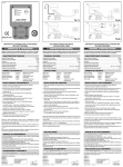
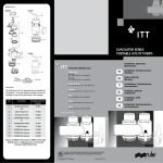
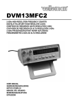
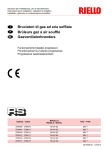
LD1/10/2012
Power on
Restart
Pump on
Failure
Fig. 2a
Fig. 1a
LOGIC-DROP
230 Vac 50 Hz Min 3 A Max. 8 A
Power on
Pump on
Restart
Power on
Pump on
Restart
Failure
Failure
g
MADE IN ITALY
Fig. 1b
DISPOSITIVO ELETTRONICO PER LA PROTEZIONE
DELL’ELETTROPOMPA
IT
MANUALE D’ ISTRUZIONI
Leggere le istruzioni prima di installare l’apparecchio e verificare che le catteristiche tecniche dell’ apparecchio e del motore della pompa siano compatibili.
CARATTERISTICHE TECNICHE
Tensione di linea monofase
Variazioni di tensione accettabili
Frequenza
Corrente minima motore pompa
Corrente massima motore pompa
Temperatura di funzionamento
Temperatura massima ambiente
“ Power on “
“ Pump on “
“ Failure “
“ Failure “
“ Restart “
GB
INSTRUCTION MANUAL
Read the instructions before installing the device and check that the technical
characteristics of the device are compatible with those of the pump motor.
TECHNICAL FEATURES
230 Vac
± 10%
50 Hz
3A
8A
min 5 °C - max 45 °C
55 °C
PANNELLO DI CONTROLLO
Led Verde acceso
Led Giallo acceso
Led Rosso intermittente
Led Rosso acceso fisso
Pulsante Rosso
ELECTRONIC PROTECTION DEVICE
FOR ELECTRICAL PUMP
INSTALLAZIONE E FUNZIONAMENTO
Green Led on
Yellow Led on
Blinking red Led
Red Led on
Red button
230 Vac
± 10%
50 Hz
3A
8A
min 5 °C - max 45 °C
55°C
4. Inserire l’ apparecchio nella presa di corrente.
Sul pannello dell’apparecchio si accendono il Led Verde “ Power on “
ed il Led Rosso intermittente “ Failure “ (Fig. 2b).
5. Premere il tasto Rosso “ Restart “ entro 10 secondi dall’inserimento
del cavo di alimentazione.
Il Led Verde “Power on “ resta acceso, il Led Giallo “ Pump on “ si
accende, il Led Rosso “ Failure “ passa da intermittente a acceso fisso e
l’apparecchio acquisisce i dati del motore (Fig. 3).
6. Attendere alcuni secondi che il Led Rosso “ Failure “ si spenga.
I dati del motore sono stati acquisiti e l’apparecchio è adesso in grado di
proteggere la pompa (Fig.4).
7. ! Chiudere l’utilizzo ed attendere la pompa si fermi (Fig.5).
E’ possibile adesso utilizzare l’impianto normalmente.
Staccare e inserire nuovamente la spina del cavo di alimentazione del motore
dall’ apparecchio, oppure l’apparecchio stesso dalla presa di corrente non compromette l’acquisizione dei dati del motore.
Qualora invece fosse necessario sostituire la pompa e/o spostare l’apparecchio su
altro impianto deve essere rifatta la procedura di acquisizione: vedere punti 2 - 3 - 4
- 5 - 6 - 7.
! In caso di sostituzione della pompa rispettare la tempistica indicata al punto 5,
diversamente l’apparecchio funzionera’ con dati non corretti.
Device energised
Pump running
Dry-running
Power surge
Acquisition motor data
Reset after fault
ANOMALIE DI FUNZIONAMENTO
DICHIARAZIONE DI CONFORMITÀ
La Ditta PENTAIR INTERNATIONAL S.a.r.l. dichiara sotto la propria responsabilita’ che
l’ apparecchio LOGIC-DROP è conforme ai Requisiti Essenziali di Sicurezza e di Tutela
della Salute di cui alle direttive:
EN60730-1
EN55014-1
PENTAIR INTERNATIONAL S.a.r.l.
EN545014-2
Avenue de Sevelin, 18
1004 LAUSANNE
EN61000-3-2
SWITZERLAND
EN61000-3-3
Vittorio
Brundu
Vitt
torio Bru
B
ndu
Lugnano ( PISA ) 11 / 02 / 2010
PLANT MANAGER
MANUEL D’INSTRUCTIONS
Lire les instructions avant d’installer l’appareil et vérifier que les caractéristiques
techniques de l’appareil et du moteur de la pompe soient compatibles.
Tension de ligne monophasée
Variations de tension acceptables
Fréquence
Courant minimum moteur pompe
Courant maximum moteur pompe
Température de fonctionnement
Température maximale environnement
230Vac
± 10%
50Hz
3A
8A
min 5 °C - max 45 °C
55°C
Voyant vert allumé
Voyant jaune allumé
Voyant rouge clignotant
Voyant rouge allumé fixe
Touche rouge
« Power on »
« Pump on »
« Failure »
« Failure »
« Restart »
Appareil sous tension
Pompe en marche
Marche à sec
Surtension
Acquisition données moteur
Reset après anomalie
INSTALLATION ET FONCTIONNEMENT
1. Check correct operation of the water system by running the pump with a tap open
(Figure 1a).
2. Disconnect the power supply plug of the pump from the power point leaving the tap
open and completely empty the system (Figure 1b).
3. Insert the power supply plug of the pump motor into the device (Figure 2a).
4. Reconnect the device to the power point.
The green “Power on” Led and the blin king red “Failure” Led will light up on the
panel of the device (Figure 2b).
5. Press the red “Restart” button within 10 seconds after connecting the power
supply cable.
The green “Power on” Led will remain on, the yellow “Pump on” Led will light up
and the red “Failure” Led will stop blinking and remain steady while the device ac
quires the motor data (Figure 3).
1. Une fois le fonctionnement correct de l’installation hydrique vérifié, faire
fonctionner la pompe en utilisation ouverte (Fig. 1a).
2. Débrancher la fiche du câble d’alimentation de la pompe de la prise de courant en
laissant l’utilisation ouverte et vidanger complètement l’installation (Fig. 1b).
3. Insérer la fiche du câble d’alimentation du moteur de la pompe dans l’appareil
(Fig.2a).
4. Bancher l’appareil à la prise de courant.
Sur le panneau de l’appareil s’allument le voyant vert « Power on » et le voyant
rouge clignotant « Failure » (Fig. 2b).
5. Appuyer sur la touche rouge « Restart » dans les 10 secondes après l’insertion du
câble d’alimentation.
Le voyant vert « Power on » reste allumé, le voyant jaune « Pump on » s’allume,
le voyant rouge « Failure » passe de clignotant à fixe et l’appareil acquiert les don
6. Wait a few seconds until the red “Failure” Led turns off.
The motor data have been acquired and the device is now capable of protecting
the pump (Figure 4).
7. ! Close the tap and wait for the pump to stop (Figure 5).
It is now possible to use the system normally.
nées du moteur (Fig. 3).
6. Attendre quelques secondes que le voyant rouge « Failure » s’éteigne.
Les données du moteur ont été acquises et l’appareil est désormais capable de
protéger la pompe (Fig. 4).
7. ! Fermer l’utilisation et attendre que la pompe s’arrête (Fig. 5).
Il est maintenant possible d’utiliser l’installation normalement.
Disconnect and reconnect the power supply cable of the motor from the device, or the
device itself from the mains power point, will not have any effect on the acquisition of
the motor data.
If instead you wish to the replace the pump and/or move the device to another pump,
please follow steps 2 – 3 – 4 -5 - 6 -7 indicated above.
! In case of replacing the pump, observe the times indicated in point 5, otherwise the
device will operate with incorrect data.
MALFUNCTIONING
In caso di funzionamento a secco il dispositivo arresta la pompa per limitare possibili
danni alla parte idraulica.
L’anomalia viene segnalata dal Led Rosso “Failure” acceso intermittente.
Se si verifica un assorbimento di corrente superiore a 8 Ampere l’ apparecchio ferma il
motore della pompa proteggendolo da sovracorrente.
L’anomalia viene segnalata dal Led Rosso “Failure” acceso fisso.
Per ripristinare il normale funzionamento dell’apparecchio e dell’ impianto è sufficiente
premere il tasto Rosso “ Restart “.
In caso di interruzione della corrente elettrica l’ apparecchio si riarma automaticamente
dopo alcuni secondi dal ritorno della stessa.
FR
PANNEAU DE CONTROLE
“Power on”
“Pump on”
“Failure”
“Failure”
“Restart”
INSTALLATION AND OPERATION
1. Verificato il corretto funzionamento dell’impianto idrico far funzionare
la pompa con un utilizzo aperto (Fig.1a).
2. Staccare la spina del cavo di alimentazione della pompa dalla presa
di corrente lasciando aperto l’ utilizzo e scaricare completamente
l’impianto (Fig. 1b).
3. Inserire la spina del cavo di alimentazione del motore della pompa
nell’apparecchio (Fig.2a).
DISPOSITIF ELECTRONIQUE POUR LA PROTECTION
DE L’ELECTROPOMPE
CARACTERISTIQUES TECHNIQUES
Single-phase mains voltage
Acceptable voltage fluctuations
Frequency
Minimum pump motor current
Maximum pump motor current
Operating temperature
Maximum ambient temperature
CONTROL PANEL
Apparecchio in tensione
Pompa in marcia
Funzionamento a secco
Sovracorrente
Acquisizione dati motore
Reset dopo anomalia
Fig. 2b
ANOMALIES DE FONCTIONNEMENT
In the case o running dry the device will stop the pump and limit possible damages to
the pump end.
This fault will be indicated by the blinking red “Failure” Led.
In the case of the input current exceeding 8 Amperes, the device will stop the pump
and protect it from power surges.
This fault will be indicated by the steady red “Failure” Led.
To restore normal operation to the device and the pump, just press the red “Restart”
button.
In the case of power supply cut-offs the device will automatically rearm a few seconds
after the power returns.
CERTIFICATE OF CONFORMITY
En cas de fonctionnement à sec, le dispositif arrête la pompe pour limiter des possibles dommages de la partie hydraulique.
L’anomalie est signalée par le voyant rouge « Failure » clignotant.
S’il y a une absorption de courant supérieure à 8 Ampères, l’appareil arrête le moteur
de la pompe en le protégeant d’une surtension.
L’anomalie est signalée par le voyant rouge « Failure » fixe.
Pour rétablir le fonctionnement normal de l’appareil et de l’installation, il suffit d’appuyer sur la touche rouge « Restart ».
En cas d’interruption du courant électrique, l’appareil se réamorce automatiquement
quelques secondes après le retour du courant.
DECLARATION CE DE CONFORMITE
The company PENTAIR INTERNATIONAL S.a.r.l. declares under its own responsibility
that the LOGIC-DROP device is compliant with the Essential Safety and Health Protection Requirements pursuant to the EN60370-1 Directives.
EN60730-1
EN55014-1
EN545014-2
PENTAIR INTERNATIONAL S.a.r.l.
Avenue de Sevelin, 18
EN61000-3-2
1004 LAUSANNE
SWITZERLAND
EN61000-3-3
Lugnano ( PISA ) 11 / 02 / 2010
Le fait de débrancher et insérer à nouveau la prise du câble d’alimentation du moteur
de l’appareil, ou bien l’appareil lui-même de la prise de courant ne compromet pas
l’acquisition des données du moteur.
S’il était par contre nécessaire de remplacer la pompe et/ou de déplacer l’appareil sur
une autre installation, il faut refaire l’acquisition : voir points 2-3-4-5-6-7.
! En cas de remplacement de la pompe, respecter la durée indiquée au point 5, sinon
l’appareil fonctionnera avec des données non correctes
Vittorio
Vitt
torio Bru
B
Brundu
ndu
PLANT MANAGER
La société PENTAIR INTERNATIONAL S.a.r.l. déclare sous sa propre responsabilité
que l’appareil LOGIC-DROP est conforme aux Critères Essentiels de Sécurité et de
Protection de la Santé des directives:
EN60730-1
EN55014-1
EN545014-2
PENTAIR INTERNATIONAL S.a.r.l.
Avenue de Sevelin, 18
EN61000-3-2
1004 LAUSANNE
SWITZERLAND
EN61000-3-3
Lugnano ( PISA ) 11 / 02 / 2010
Vittorio
Vitt
torio Bru
B
Brundu
ndu
PLANT MANAGER
Power on
Pump on
Power on
Restart
Pump on
Failure
ELEKTRONISCHE SCHUTZVORRICHTUNG
DER ELEKTROPUMPE
GEBRAUCHSANLEITUNG
Lesen Sie vor dem Einbau des Geräts die Gebrauchsanleitung und überprüfen
Sie, dass die technischen Eigenschaften des Geräts und des Pumpenmotors
kompatibel sind.
Fig. 4
ЭЛЕКТРОННОЕ ЗАЩИТНОЕ УСТРОЙСТВО
ДЛЯ ЭЛЕКТРИЧЕСКИХ НАСОСОВ
RU РУКОВОСТВО ПО ЭКСПЛУАТАЦИИ
Перед монтажом внимательно прочитайте инструкцию и проверьте
взаимное соответствие характеристик устройства и электродвигателя
ТЕХНИЧЕСКИЕ ХАРАКТЕРИСТИКИ
TECHNISCHE EIGENSCHAFTEN
Einphasige Leiterspannung
Zulässige Spannungsänderungen
Frequenz
Mindeststrom Pumpenmotor
Höchststrom Pumpenmotor
Betriebstemperatur
Maximale Umgebungstemperatur
230 Vac
± 10%
50 Hz
3A
8A
mind 5 °C - max 45 °C
55 °C
Однофазное напряжение
Допуск значения напряжения
Частота
Минимальный ток электродвигателя
Максимальный ток электродвигателя
Температура перекачиваемой водой
Температура окружающей среды
BEDIENFELD
„Power on“
„Pump on“
„Failure“
„Failure“
„Restart“
Gerät unter Spannung
Pumpe in Betrieb
Trockenlauf
Überspannung
Erfassung Motordaten
Zurücksetzen nach Störung
INSTALLATION UND BETRIEB
1. Nachdem der korrekte Betrieb der hydraulischen Anlage überprüft wurde, die Pum
pe mit offener Anwendung in Betrieb nehmen (Abb. 1a).
2. Den Stecker des Netzkabels der Pumpe herausziehen und die Anwendung offen
lassen; die Anlage vollständig entleeren (Abb. 1b).
3. Den Stecker des Netzkabels des Pumpenmotors an das Gerät anschließen (Abb.
2a).
4. Das Gerät an die Netzsteckdose anschließen. Auf dem Bedienfeld des Geräts
leuchtet die grüne Led „Power on“, und die rote Led „Failure“ blinkt (Abb. 2b).
5. Innerhalb von 10 Sekunden nach Anschluss des Netzkabels die rote Taste
„Restart“ betätigen. Die grüne Led „Power on“ leuchtet weiterhin, die gelbe Led
„Pump on“ leuchtet ebenfalls, die rote Led „Failure“ leuchtet jetzt durchgehend
und das Gerät erfasst die Motordaten (Abb. 3).
6. Warten Sie einige Sekunden, bis die rote Led „Failure“ erlischt. Die Motordaten wur
den erfasst und das Gerät ist jetzt in der Lage, die Pumpe zu schützen (Abb. 4).
7. ! Schließen Sie die Anwendung und warten Sie, bis die Pumpe ausgeht (Abb. 5).
Jetzt kann die Anlage normal verwendet werden.
Den Stecker des Netzkabels des Motors herauszuziehen und wieder einzustecken
oder das Gerät vom Strom abzunehmen, hat keinen Einfluss auf die Erfassung der
Motordaten.
Wenn die Pumpe ausgewechselt und/oder das Gerät auf einer anderen Anlage installiert werden muss, muss der Vorgang der Datenerfassung wiederholt werden: siehe
Punkte 2 – 3 – 4 – 5 – 6 – 7.
! Wenn die Pumpe ausgewechselt werden muss, beachten Sie die Zeitvorgaben in
Punkt 5, da das Gerät ansonsten mit nicht korrekten Daten läuft.
«Power on»
«Pump on»
«Failure»
«Failure»
«Restart»
Im Trockenlaufbetrieb wird die Pumpe von der Vorrichtung angehalten, damit die
Hydraulikanlage nicht beschädigt wird.
Die Störung wird durch die blinkende rote Led „Failure“ angezeigt. Wenn Strom von
mehr als 8A absorbiert wird, stoppt das Gerät den Pumpenmotor und schützt ihn so
vor Überspannung.
Zur Wiederherstellung des normalen Betriebs des Geräts und der Anlage betätigen Sie
einfach die rote Taste „Restart“. Bei Stromunterbrechungen startet das Gerät automatisch einige Sekunden, nach Ende der Stromunterbrechung.
МОНТАЖ И ЭКСПЛУАТАЦИЯ
Die Firma PENTAIR INTERNATIONAL S.a.r.l. erklärt unter eigener Haftung, dass das
Gerät LOGIC-DROP mit den wesentlichen Sicherheits- und Gesundheitsbestimmungen folgender Vorschriften konform ist:
EN60730-1
EN55014-1
EN545014-2
PENTAIR INTERNATIONAL S.a.r.l.
Avenue de Sevelin, 18
EN61000-3-2
1004 LAUSANNE
SWITZERLAND
EN61000-3-3
Vittorio
Vitt
torio Bru
B
Brundu
ndu
PLANT MANAGER
Lees de instructies alvorens het apparaat te installeren en controleer of de technische kenmerken van het apparaat en van de pompmotor overeenkomen.
Eenfase-netspanning
Toelaatbare spanningsschommelingen
Frequentie
Min. stroom pompmotor
Max. stroom pompmotor
Bedrijfstemperatuur
Max. omgevingstemperatuur
230 Vac
± 10%
50 Hz
3A
8A
min 5 °C - max 45 °C
55 °C
Groene led brandt
Gele led brandt
Rode led knippert
Rode led brandt
Rode knop
“Power on”
“Pump on”
“Failure”
“Failure”
“Restart”
Spanning apparaat ingeschakeld
Pomp in werking
Pomp loopt droog
Overbelasting
Overname motorgegevens
Reset na storing
1. Na controle van de werking van het waterleidingsysteem de pomp met een open
afnamepunt laten werken (Fig. 1a).
2. Haal de stekker van de voedingskabel van de pomp uit het stopcontact, laat het
afnamepunt open en laat het systeem geheel leeglopen (Fig. 1b).
3. Steek de stekker van de voedingskabel van de pompmotor in het apparaat (Fig.
2a).
4. Sluit het apparaat aan op het stopcontact.
Op het paneel van het apparaat gaan de groene led “Power on” en de knipperende
rode led “Failure” aan (Fig. 2b).
5. Druk binnen 10 seconden na het aansluiten van de voedingskabel op de rode toets
“Restart”.
De groene led “Power on” blijft branden, de gele led “Pump on” gaat aan, de knip
perende rode led “Failure” blijft continu branden en het apparaat neemt de motor
gegevens over (Fig. 3).
6. Wacht enkele seconden tot de rode led “Failure” uit gaat.
De gegevens van de motor zijn overgenomen en het apparaat is nu in staat om de
pomp te beschermen (Fig. 4).
7 ! Sluit het afnamepunt en wacht tot de pomp is gestopt (Fig. 5).
Nu kan het systeem normaal worden gebruikt.
In geval van af- en aankoppelen van de stekker van de voedingskabel van de motor
op het apparaat, of het apparaat op het stopcontact, blijft de overname van de motorgegevens onveranderd.
Indien het nodig is de pomp te vervangen en/of het apparaat naar een ander systeem
te verplaatsen, dan moet de overnameprocedure opnieuw worden uitgevoerd: zie de
punten 2 – 3 – 4 –5 – 6 – 7.
! In geval van vervanging van de pomp dient men zich aan de in punt 5 aangegeven
tijden te houden, anders werkt het apparaat met onjuiste gegevens.
STORINGEN
Если в насос перестает поступать вода, защитное устройство отключает
электродвигатель, защищая насосную часть от «сухого хода». При этом ошибка «Нет
воды» обозначается мигающим красным индикатором «Failure».
Если значение потребляемого тока превышает 8 А, защитное устройство отключает
электродвигатель, защищая от перегрева. Ошибка «Повышенный ток» обозначается
непрерывно горящим красным индикатором «Failure».
Для возобновления нормальной работы насосы после устранения условий,
вызывающих появление ошибки, следует нажать красную кнопку «Restart». В случае
перебоев с электропитанием защитное устройство автоматически включается
спустя несколько секунд после того, как электропитание появится вновь.
Indien de pomp droog loopt stopt het apparaat de pomp zodat eventuele schade aan
het hydraulisch gedeelte gelimiteerd wordt.
De storing wordt gemeld door de knipperende rode led “Failure”.
Indien een stroomopname boven de 8 Ampère optreedt stopt het apparaat de pompmotor om hem tegen overbelasting te beschermen.
De storing wordt gemeld door de continu brandende rode led “Failure”.
Om de normale werking van het apparaat en van het systeem te herstellen is een druk
op de rode toets “Restart” voldoende.
In geval van een stroomonderbreking wordt het apparaat enkele seconden na terugkeer van de stroom automatisch gereset.
VERKLARING VAN OVEREENSTEMMING
Компания PENTAIR INTERNATIONAL S.a.r.l декларирует под свою
ответственность, что защитное устройство LOGIC DROP соответствует основным
требованиям безопасности и защиты здоровья, указанных в Директивах:
EN60730-1
EN55014-1
EN545014-2
PENTAIR INTERNATIONAL S.a.r.l.
Avenue de Sevelin, 18
EN61000-3-2
1004 LAUSANNE
SWITZERLAND
EN61000-3-3
Lugnano ( PISA ) 11 / 02 / 2010
NL GEBRUIKERSHANDLEIDING
INSTALLATIE EN WERKING
1. Проверьте работоспособность системы при включенном насосе и открытом
водопроводном кране (рис.1а).
2. Отключите вилку насоса от электророзетки, оставив кран отрытым, и слейте
всю воду из напорной трубы (рис. 1 b).
3. Вставьте вилку насоса в защитное устройство (рис. 2 а).
4. Подключите защитное устройство к электророзетке. На контрольной панели
загорится зеленый индикатор «Power on» и мигающий красный индикатор
«Failure» (рис. 2 b).
5. После подключения питания нажмите красную кнопку «Restart»
и удерживайте ее в течение 10 секунд.
Зеленый индикатор «Power on» будет по-прежнему гореть,
дополнительно загорится желтый индикатор «Pump on» , а
красный индикатор «Failure» перестанет мигать, и будет гореть, пока
происходит сбор данных электродвигателя (рис.3).
6. Подождите несколько секунд, пока красный индикатор «Failure» не
погаснет. Данные электродвигателя собраны, защитное устройство готово к
работе (рис.4).
7. ! Закройте водопроводный кран и убедитесь, что насос выключится
(рис.5).Теперь система готова к использованию.
Повторное отключение вилки насоса от защитного устройства или самого
устройства от электророзетки не повлияет на его настройки, полученные в ходе
сбора данных электродвигателя.
Если Вам нужно будет переустановить это устройство на другой электронасос,
повторите описанные выше действия пунктов 2-3-4-5-6-7.
! При настройке защитного устройства на другом электронасосе в соответствии
с пунктом 5 обеспечьте время удержания кнопки «Restart», иначе настройки
устройства будут неправильными.
ДЕКЛАРАЦИЯ О СООТВЕТСТВИИ
EG-KONFORMITÄTSERKLÄRUNG
ELEKTRONISCHE BEVEILIGING VAN
DE ELEKTROPOMP
BEDIENINGSPANEEL
Напряжение подано
Насос работает
Нет воды
Повышенный ток
Сбор данных электродвигателя
Сброс ошибки
ОПРЕДЕЛЕНИЕ ОШИБОК
BETRIEBSSTÖRUNG
Lugnano ( PISA ) 11 / 02 / 2010
Зеленый индикатор
Желтый индикатор
Мигающий красный
Красный индикатор
Красная кнопка
Fig. 5
TECHNISCHE KENMERKEN
1 х 230В
± 10%
50 Гц
3А
8А
min +5°C – max +45°
55°C
КОНТРОЛЬНАЯ ПАНЕЛЬ
Grüne Led leuchtet
Gelbe Led leuchtet
Rote Led blinkt
Rote Led leuchtet
Rote Taste
Restart
Pump on
Failure
Fig. 3
DE
Power on
Restart
Vittorio
Vitt
torio Bru
B
Brundu
ndu
PLANT MANAGER
De firma PENTAIR INTERNATIONAL S.a.r.l. verklaart onder eigen verantwoordelijkheid
dat het apparaat LOGIC-DROP in overeenstemming is met de essentiële vereisten op
het gebied van veiligheid en bescherming van de gezondheid volgens de richtlijnen:
EN60730-1
EN55014-1
EN545014-2
PENTAIR INTERNATIONAL S.a.r.l.
Avenue de Sevelin, 18
EN61000-3-2
1004 LAUSANNE
SWITZERLAND
EN61000-3-3
Lugnano ( PISA ) 11 / 02 / 2010
Vittorio
Vitt
torio Bru
B
Brundu
ndu
PLANT MANAGER