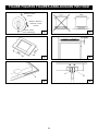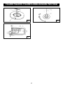
1
ISTRUZIONI PER L’ISTALLAZIONE E L’USO DEI PIANI DI COTTURA A GAS IN CRISTALLO IT GB INSTRUCTIONS FOR USE AND MAINTENANCE OF HOBS FR NOTICE D’INSTALLATION ET UTILISATION DE TABLES DE CUISSON DE ANLEITUNGEN FUR DEN EINBAU UND DEN GEBRAUCH DER KOCHMULDEN RUS BO 210 VB/N BO 219 VD/N BO 210 VC/N BO 219 VE/N BO 210 VC/L BO 292 VB/N BO 210 OM/L BO 293 VB/N BO 217 VD/A BO 297 VA/N BO 217 VB/N BO 297 VB/N BO 217 VB/L BO 297 VB/L BO 219 VB/N BO 297 VD/N BO 219 VC/N BO 297 VD/L COD. 208006-07 - 25.10.2011 itindice Avvertenze generalip. 3 Istruzioni per l’utentep. 4 Uso dei bruciatorip. 4 Puliziap. 5 Tabelle caratteristiche tecniche p. 4 Istruzioni per l’installatore p. 6 Installazionep. 6 Trasformazioni gas e regolazioni p. 7 Manutenzione p. 7 Descrizione piani cotturap. 32 Figurep. 33 Gentile Cliente, La ringraziamo e ci congratuliamo per la preferenza accordataci con l’acquisto di un nostro prodotto. Siamo certi che questo nuovo apparecchio, costruito con materiali di qualità, soddisferà nel modo migliore Le sue esigenze. L’uso di questa nuova apparecchiatura è facile, tuttavia La invitiamo a leggere attentamente questo libretto prima di installare ed usare l’apparecchio. Il libretto fornisce le indicazioni corrette sull’installazione, l’uso e la munutenzione oltre a dare utili consigli. IL COSTRUTTORE 2 IT AVVERTENZE GENERALI La invitiamo a leggere questo libretto istruzioni prima di installare e di utilizzare l’apparecchiatura. E’ molto importante che il libretto sia conservato assieme all’apparecchiatura per qualsiasi futura consultazione. Se l’apparecchiatura dovesse essere venduta o trasferita ad un’altra persona,assicurarsi che il libretto venga fornito assieme,in modo che il nuovo utente possa essere messo al corrente del funzionamento e delle relative avvertenze. Questo apparecchio è di classe 3 ed è stato concepito per un impiego non di tipo professionale da parte di privati all’interno di abitazioni. -- L’installazione deve essere eseguita da personale competente e qualificato secondo le norme vigenti. -- Quest’apparecchiatura è stata progettata per essere utilizzata da adulti. -- Questo apparecchio non è destinato all’ uso da parte di persone (inclusi i bambini) con ridotte capacità psichiche o motorie, o con mancanza di esperienza e conoscenza, a meno che ci sia una supervisione o istruzione sull’ uso dell’ apparecchio da parte di una persona responsabile per la loro sicurezza. -- I bambini devono essere sorvegliati per assicurarsi che non giochino con l’ apparecchio. -- Prima di alimentare l’apparecchiatura controllare che sia correttamente regolata per il tipo di gas a disposizione (vedi paragrafo “ installazione”). -- Prima della manutenzione o della pulizia disinserire elettricamente l’apparecchiatura e lasciarla raffreddare. -- Assicurarsi che ci sia una circolazione d’aria attorno all’apparecchiatura a gas . Una scarsa ventilazione produce carenza di ossigeno. -- Nel caso di un utilizzo intenso o prolungato dell’apparecchio può necessitare di una areazione supplementare, per esempio l’apertura di una finestra o aumentando la potenza di aspirazione meccanica se esiste. -- I prodotti della combustione devono essere scaricati all’esterno attraverso una cappa aspirante o elettroventilatore (vedi paragrafo “installazione”). -- Per eventuali interventi o modifiche rivolgersi ad un Centro di Assistenza Tecnica autorizzato ed esigere parti di ricambio originali. ll costruttore declina ogni responsabilità nel caso di eventuali danni a cose o persone, derivanti da una installazione non corretta o da un uso improprio,erroneo od irragionevole dell’apparecchio. Questo prodotto è conforme alla Direttiva EU 2002/96/EC. Il simbolo del cestino barrato riportato sull’apparecchio indica che il prodotto, alla fine della propria vita utile, dovendo essere trattato separatamente dai rifiuti domestici, deve essere conferito in un centro di raccolta differenziata per apparecchiature elettriche ed elettroniche oppure riconsegnato al rivenditore al momento dell’acquisto di una nuova apparecchiatura equivalente. L’utente è responsabile del conferimento dell’apparecchio a fine vita alle appropriate strutture di raccolta, pena le sanzioni previste dalla vigente legislazione sui rifiuti. L’adeguata raccolta differenziata per l’avvio successivo dell’apparecchio dismesso al riciclaggio, al trattamento e allo smaltimento ambientalmente compatibile contribuisce ad evitare possibili effetti negativi sull’ambiente e sulla salute e favorisce il riciclo dei materiali di cui è composto il prodotto. Per informazioni più dettagliate inerenti i sistemi di raccolta disponibili, rivolgersi al servizio locale di smaltimento rifiuti, o al negozio in cui è stato effettuato l’acquisto. I produttori e gli importatori ottemperano alla loro responsabilità per il riciclaggio, il trattamento e lo smaltimento ambientalmente compatibile sia direttamente sia partecipando ad un sistema collettivo 3 IT ISTRUZIONI PER L’UTENTE E’ necessario che tutte le operazioni relative all’installazione, alla regolazione, all’adattamento al tipo gas disponibile, vengano eseguite da personale qualificato, secondo le norme in vigore. Le istruzioni specifiche sono descritte nella parte del libretto riservate all’installatore. USO DEI BRUCIATORI La simbologia serigrafata a lato delle manopole,indica la corrispondenza tra manopola e bruciatore. Accensione automatica senza valvolatura Ruotare in senso antiorario la manopola corrispondente fino alla posizione di massimo (fiamma grande fig.1) e premere la manopola. Bruciatori Potenze W Ø Pentole Ausiliario 1000 10 - 14 cm Semirapido 1650 16 - 18 cm Rapido 3000 20 - 22 cm Tripla corona 3500 24 - 26 cm Avvertenze -- Controllare sempre che le manopole siano nella posizione di chiuso (vedi fig.1) quando l’apparecchiatura non è in funzione. -- In caso di spegnimento accidentale della fiamma ,la valvola di sicurezza,dopo qualche secondo, interromperà automaticamente l’erogazione del gas. Per ripristinare il funzionamento riportare la manopola al punto di accensione ( fiamma grande fig.1). -- Durante la cottura con grassi o olii, porre la massima attenzione in quanto gli stessi, surriscaldandosi, possono infiammarsi. -- Non utilizzare spray vicino all’apparecchio in funzione. -- Non devono essere poste sul bruciatore pentole instabili o deformate per evitare incidenti di rovesciamento o trabocco. -- Assicurarsi che le maniglie delle pentole siano posizionate correttamente. -- Quando si accende il bruciatore controllare che la fiamma sia regolare , abbassare sempre la fiamma o spegnerla prima di togliere le pentole. Accensione automatica con valvolatura Ruotare in senso antiorario la manopola corrispondente fino alla posizione di massimo (fiamma grande fig. 1) e premere la manopola. Ad accensione avvenuta mantenere premuta la manopola per circa 10 secondi. Uso dei bruciatori Per ottenere il massimo della resa senza spreco di gas è importante che il diametro della pentola sia adeguato alla potenzialità del bruciatore (vedi tabella seguente), in modo da evitare che la fiamma esca dal fondo della pentola (fig. 2). Utilizzare la portata massima per portare rapidamente in ebollizzione i liquidi e quella ridotta per riscaldare le vivande o per il mantenimento dell’ebollizione. Tutte le posizioni di funzionamento devono essere scelte tra quelle di massimo e quella di minimo, mai tra la posizione di massimo e il punto di chiusura. Per interrompere l’alimentazione gas ,ruotare la manopola in senso orario sulla posizione di chiusura. In mancanza di energia elettrica è possibile accendere i bruciatori con i fiammiferi posizionando la manopola al punto di accensione (fiamma grande fig. 1). 4 IT ISTRUZIONI PER L’UTENTE PULIZIA Bruciatori e griglie Questi pezzi possono essere tolti per facilitare la pulizia. I bruciatori devono essere lavati con una spugna ed acqua saponata o con detersivo leggero, ben asciugati e rimessi perfettamente nel loro alloggiamento. Controllare che i canali spartifiamma non siano ostruiti. Verificare che la sonda della valvola di sicurezza e l’elettrodo di accensione siano sempre ben puliti per garantire un funzionamento ottimale. Rubinetti a gas L’eventuale lubrificazione dei rubinetti deve essere eseguita esclusivamente da personale specializzato. In caso di indurimento o di anomalie di funzionamento dei rubinetti gas chiamare il Servizio di Assistenza. Prima di ogni operazione scollegare l’apparecchio dalla rete di alimentazione elettrica. Non utilizzare pulitori a vapore per la pulizia dell’apparecchio. Si consiglia di operare ad apparecchio freddo. Pianale vetro e parti smaltate Il pianale in vetro e tutte le parti smaltate devono essere lavate con una spugna ed acqua saponata o con detersivo leggero. Non usare prodotti abrasivi o corrosivi. Evitate che sostanze come succo di limone, pomodoro, acqua salina, aceto, caffè e latte rimangano a lungo sulle superfici smaltate. IT TABELLA CARATTERISTICHE TECNICHE BRUCIATORI N° 1 2 3 4 GAS DENOMINAZIONE RAPIDO SEMIRAPIDO AUSILIARIO TRIPLA CORONA PRESSIONE ESERCIZIO PORTATA TERMICA DIAMETRO UGELLO DIAMETRO BY PASS RUBINETTI PORTATA TERMICA (W) mbar g/h L/h 1/100 mm 1/100 mm Max. Min. G30 28-30 218 - 87 42 3000 950 G31 37 214 - 87 42 3000 950 G20 20 - 286 129 Reg. 3000 950 G30 28-30 120 - 65 31 1650 600 G31 37 118 - 65 31 1650 600 G20 20 - 157 97 Reg. 1650 600 G30 28-30 73 - 50 27 1000 450 G31 37 71 - 50 27 1000 450 G20 20 - 95 77 Reg. 1000 450 G30 28-30 255 - 94 60 3500 2100 G31 37 250 - 94 60 3500 2100 G20 20 - 334 141 Reg. 3500 2100 230 V~ 50/60 Hz 5 IT ISTRUZIONI PER L’INSTALLATORE AVVERTENZA IMPORTANTE LE OPERAZIONI DI SEGUITO RIPORTATE DEVONO ESSERE ESEGUITE, NEL RISPETTO DELLE NORME VIGENTI, ESCLUSIVAMENTE DA PERSONALE QUALIFICATO. LA DITTA COSTRUTTRICE DECLINA OGNI RESPONSABILITA’ PER DANNI A PERSONE ANIMALI O COSE DERIVANTI DALL’INNOSSERVANZA DI TALI DISPOSIZIONI. INSTALLAZIONE Locale di installazione Questo apparecchio non è provvisto di un dispositivo di scarico dei prodotti della combustione, è necessario quindi scaricare questi fumi all’esterno utilizzando una cappa o un elettroventilatore che entri in funzione ogni volta che si utilizza l’apparecchio. Il locale dove viene installato l’apparecchio deve avere un naturale afflusso d’aria per la regolare combustione del gas e per la ventilazione del locale ; il volume d’aria necessario non deve essere inferiore a 20 m3. L’afflusso dell’aria deve avvenire da aperture permanenti praticate sulle pareti del locale comunicanti con l’esterno. La ventilazione può provvenire anche da un locale attiguo , in questo caso attenersi a quanto prescritto dalle norme UNI-CIG 7129 e 7131. Le aperture dovranno avere una sezione minima di 200 cm2. Montaggio del piano L’apparecchio è costruito per essere incassato in mobili resistenti al calore. Le pareti dei mobili devono resistere ad una temperatura di 65°C oltre a quella ambientale secondo le normative europee EN 30 335-1-2-6. L’apparecchio è di tipo “ Y “ , ovvero può essere installato con una sola parete laterale a destra o a sinistra del piano cottura. Evitare l’installazione dell’apparecchiatura in prossimità di materiali infiammabili come tendaggi, canevacci, ecc. Praticare un’apertura nel piano del mobile delle dimensioni indicate nella fig.3 rispettando una distanza di almeno 50 mm dal bordo dell’apparecchio alle pareti adiacenti . L’eventuale presenza di un pensile al di sopra del piano cottura deve prevedere una distanza minima dal top di 760 mm. Si consiglia di isolare l’apparecchio dal mobile sottostante con un separatore lasciando uno spazio di depressione di almeno 10 mm. (fig.4). Questo apparecchio è di classe 3. Collegamento gas Accertarsi che l’apparecchio sia predisposto al tipo di gas disponibile, vedi l’etichetta sotto l’apparecchio o quella riportata all’ultima pagina di questo libretto. Operare secondo le istruzioni riportate al paragrafo “trasformazioni gas e regolazioni” per l’eventuale adattamento a gas diversi. L’apparecchio deve essere collegato all’impianto gas utilizzando tubi metallici rigidi conformi alla norma UNI-CIG 7129 o con tubi flessibili in acciaio a parete continua conformi alla norma UNI-CIG 9891. Il raccordo di entrata gas dell’apparecchio è filettato ½ gas cilindrico maschio. Il collegamento non deve provocare sollecitazioni alla rampa gas. Ad installazione ultimata controllare la tenuta dei collegamenti con una soluzione saponosa. Fissaggio del piano Ogni piano di cottura viene corredato di una speciale guarnizione con lato adesivo . -- Togliere dal piano griglie e bruciatori. -- Rovesciare l’apparecchio e stendere lungo il bordo esterno del vetro la guarnizione adesiva S (fig.5). -- Inserire e posizionare il piano cottura nell’apertura praticata nel mobile e bloccarlo con le viti V dei ganci di fissaggio G (fig. 6). 6 IT ISTRUZIONI PER L’INSTALLATORE Collegamento elettrico L’allacciamento alla rete elettrica deve essere eseguito da personale qualificato e secondo le norme vigenti. La tensione dell’impianto elettrico deve corrispondere a quelle indicata sulla etichetta sotto l’apparecchio. Verificare che l’impianto elettrico sia munito di un efficace collegamento di terra secondo le norme e le disposizioni di legge. La messa a terra è obbligatoria. Se l’apparecchio è sprovvisto di spina, applicare al cavo di alimentazione una spina normalizzata. Per il collegamento diretto alla rete, è necessario prevedere un dispositivo che assicuri la disconnessione dalla rete, con una distanza di apertura dei contatti che consenta la disconnessione completa nelle condizioni della categoria di sovratensione III, conformemente alle regole di installazione. MANUTENZIONE Sostituzione cavo alimentazione In caso di sostituzione del cavo di alimentazione si dovrà utilizzare un cavo a norme del tipo H05VV-F o H05RR-F di sezione 3 x 0,75 mm2. Il collegamento alla morsettiera va eseguito come illustrato in fig. 9: cavetto L marrone cavetto N blu verde-giallo cavetto TRASFORMAZIONI GAS E REGOLAZIONI Sostituzione ugelli Se l’apparecchiatura risulta predisposta per un diverso tipo di gas di quello disponibile è necessario sostituire gli ugelli dei bruciatori. La scelta degli ugelli da sostituire deve essere fatta secondo la tabella “caratteristiche tecniche”. Procedere quindi come segue: -- Togliere le griglie e i bruciatori. -- Con una chiave diritta L svitare l’ugello U (fig. 7) e sostituirlo con quello corrispondente. -- Bloccare energicamente l’ugello. Regolazione bruciatori La regolazione del minimo deve essere sempre corretta e la fiamma deve rimanere accesa anche con un brusco passaggio dalla posizione di massimo a quella di minimo. Se questo non avviene è necessario regolare il minimo come segue: -- Accendere il bruciatore; -- Ruotare il rubinetto fino alla posizione di minimo (fiamma piccola); -- Sfilare la manopola dall’asta del rubinetto; -- Introdurre un cacciavite a taglio C nel foro F del rubinetto (fig.8) e ruotare la vite by-pass fino ad una corretta regolazione del minimo. Per bruciatori funzionanti a gas G30 la vite bypass deve essere avvitata completamente. 7 (fase) (neutro) (terra) CENTRI ASSISTENZA TECNICA Per Assistenza Tecnica Autorizzata e Ricambi Originali rivolgersi al numero unico* Numero unico 848 99 87 03 Oppure visitare il sito www.bompani.it * al costo massimo di 2 centesimi di euro al minuto (iva inclusa) anche da cellulare. CONDIZIONI DI GARANZIA Le Condizioni di Garanzia sono consultabili sul nostro sito www.bompani.it 8 GB INDEX General notice p. 9 Instructions for the user p. 10 Using the burnersp. 10 Cleaningp. 11 Technical characteristic tablesp. 11 Instructions for the installerp. 12 Installationp. 12 Gas transformations and adjustments p. 13 Maintenance p. 13 Description of the cook-topsp. 32 Figuresp. 33 Dear Customer, We thank you and congratulate you on granting us your preference, by purchasing one of our products. We are sure that this new appliance, manufactured with quality materials, will meet your requirements in the best possible way. The use of this new equipment is easy. However, we invite you to read this booklet carefully, before installing and using the appliance. This booklet gives the right information on the installation, use and maintenance, as well as useful advice. THE MANUFACTURER 9 GB GENERAL NOTICE We invite you to read this instruction booklet carefully, before installing and using the equipment. It is very important that you keep this booklet together with the equipment for any future consultation. If this equipment should be sold or transferred to another person, make sure that the new user receives the booklet, so that he can learn how to operate the appliance and read the corresponding notice. -- The installation must be carried out by experienced and qualified personnel, in conformity with the regulations in force. -- This equipment has been designed to be used by adults. -- This appliance is not intended for use by person (including children) with reduced physical, sensory or mental capabilities, or lack of experience and knowledge, unless they have been given supervision or instruction cencerning use of the appliance by a person responsible for their safety. -- Children should be supervised to ensure that they do not play with the appliance. -- Before powering the equipment, check that it is properly adjusted for the type of gas at disposal (see the “installation” paragraph). -- Before carrying out the maintenance or cleaning the equipment, cut power supply off and make it cool down. -- Make sure that air circulates around the gas equipment. Insufficient ventilation produces a lack of oxygen. -- In case of an intense or prolonged use of the equipment, it may be necessary to improve aeration, for example by opening a window or increasing the mechanical suction power, if it exists. -- The products of combustion must be discharged outside through a suction hood or an electric fan (see the “installation” paragraph). -- For any possible operation or modification, apply to an authorized Technical Assistance Centre and demand original spare parts. The manufacturer refuses all responsibility for possible damages to things or people, resulting from a wrong installation or from an improper, incorrect or unreasonable use of this equipment. This product complies with EU Directive 2002/96/EC. The crossed-out dustbin symbol reported on the appliance indicates that the appliance must be disposed of separately from other domestic refuse at the end of its useful life. It must therefore be delivered to a waste recycling centre specifically for electric and electronic equipment or returned to the retailer at the moment of purchase of a new equivalent appliance. The user is responsible for delivering the appliance to the appropriate collection centre at the end of its useful life, Failure to do so may result in a fine, as provided for by laws governing waste disposal. Differential collection of waste products for eventual recycling, treatment and environmentally friendly disposal helps reduce possible negative effects on the environment and health, and also enables the materials making up the product to be recycled. For more detailed information on the available refuse collection systems, refer to the local Municipal Solid Waste disposal centre or the shop where the product was purchased. Producers and importers are responsible for fulfilling their obligations as regards recycling, treatment and environmentally friendly disposal by directly or indirectly participating in the collection system. 10 GB INSTRUCTIONS FOR THE USER It is necessary that all the operations regarding the installation, adjustment and adaptation to the type of gas available are carried out by qualified personnel, in conformity with the regulations in force. The specific instructions are described in the booklet section intended for the installer. USING THE BURNERS The symbols silk-screen printed on the side of the knob indicate the correspondence between the knob and the burner. Start-up without valves Turn the corresponding knob anticlockwise up to the maximum position (large flame, fig.1) and press start-up button P (fig.1). Burners Power W Ø of pots Auxiliary 1000 10 - 14 cm Semi-rapid 1650 16 - 18 cm Rapid 3000 20 - 22 cm Triple ring 3500 24 - 26 cm Notice -- When the equipment is not working, always check that the knobs are in the closing position (see fig.1). -- If the flame should blow out accidentally, the safety valve will automatically stop the gas supply, after a few seconds. To restore operation, set the knob to the lighting point (large flame, fig.1). -- While cooking with fat or oil, pay the utmost attention as these substances can catch fire when overheated. -- Do not use sprays near the appliance in operation. -- Do not place unstable or deformed pots on the burner, so as to prevent them from overturning or overflowing. -- Make sure that pot handles are placed properly. -- When the burner is started up, check that the flame is regular and, before taking pots away, always lower the flame or put it out. Automatic start-up with valves Turn the corresponding knob anticlockwise up to the maximum position (large flame, fig. 1) and press the knob. Once the burner has been started up, keep the knob pressed for about 10 seconds. Using the burners In order to obtain the maximum yield without waste of gas, it is important that the diameter of the pot is suitable for the burner potential (see the following table), so as to avoid that the flame goes out of the pot bottom (fig. 2). Use the maximum capacity to quickly make the liquids reach the boiling temperature, and the reduced capacity to heat food or maintain boiling. All of the operating positions must be chosen between the maximum and the minimum ones, never between the minimum position and the closing point. The gas supply can be interrupted by turning the knob clockwise up to the closing position. If there is no power supply, it is possible to light the burners with matches, setting the knob to the startup point (large flame, fig. 1). 11 gb Instructions for the user CLEANING Burners and racks These parts can be removed to make cleaning easier. The burners must be washed with a sponge and soapy water or with a light detergent, wiped well and placed in their housing perfectly. Make sure that the flame-dividing ducts are not clogged. Check that the feeler of the safety valve and the start-up electrode are always perfectly cleaned, so as to ensure an optimum operation. Before any operation, disconnect the appliance from the electric grid. Don’t use a steam cleaner for the cleaning the hob. It is advisable to clean the appliance when it is cold. Glass platform and enamelled part The glass platform and all of the enamelled parts must be washed with a sponge and soapy water or with a light detergent. Do not use abrasive or corrosive products. Do not leave substances, such as lemon or tomato juice, salt water, vinegar, coffee and milk on the enamelled surfaces for a long time. gb TECHNICAL CARACTERISTIC TABLES BURNERS GAS N° DESCRIPTION 1 RAPID 2 3 4 Gas taps The possible lubrication of the taps must be carried out by specialized personnel, exclusively. In case of hardening or malfunctions in the gas taps, apply to the Customer Service. SEMI-RAPID AUXILIARY TRIPLE RING NORMAL PRESSURE NOMINAL RATE INJECTOR DIAMETER TAP BY PASS DIAMETER NOMINAL HEAT INPUT (W) mbar g/h L/h 1/100 mm 1/100 mm Max. Min. G30 28-30 218 - 87 42 3000 950 G31 37 214 - 87 42 3000 950 G20 20 - 286 129 Reg. 3000 950 G30 28-30 120 - 65 31 1650 600 G31 37 118 - 65 31 1650 600 G20 20 - 157 97 Reg. 1650 600 G30 28-30 73 - 50 27 1000 450 G31 37 71 - 50 27 1000 450 G20 20 - 95 77 Reg. 1000 450 G30 28-30 255 - 94 60 3500 2100 G31 37 250 - 94 60 3500 2100 G20 20 - 334 141 Reg. 3500 2100 230 V~ 50/60 Hz 12 GB INSTRUCTIONS FOR THE USER IMPORTANT NOTICE THE OPERATIONS INDICATED BELOW MUST BE FOLLOWED BY QUALIFIED PERSONNEL EXCLUSIVELY, IN CONFORMITY WITH THE REGULATIONS IN FORCE. THE MANUFACTURING FIRM REFUSES ALL RESPONSIBILITY FOR DAMAGES TO PEOPLE, ANIMALS OR THINGS, RESULTING FROM THE FAILURE TO COMPLY WITH SUCH PROVISIONS. INSTALLATION Installation room This appliance is not provided with a device for exhausting the products of combustion. Therefore, it is necessary to discharge these smokes outside. The room where this appliance is installed must have a natural air inflow, so as to ensure a regular gas combustion and room ventilation: the necessary air volume must not be lower than 20m3. Air must come from permanent openings made on the room walls that communicate with the outside. The section of these openings shall correspond to at least 200 cm2. Installing the top The appliance is designed to be embedded into heat-resistant pieces of furniture. The walls of the pieces of furniture must resist a temperature of 65°C besides the room one. The equipment must not be installed near inflammable materials, such as curtains, cloths, etc. Make a hole in the top of the piece of furniture, with the dimensions indicated in fig.3, at a distance of at least 50 mm from the appliance border to the adjacent walls. Any possible wall unit over the cook-top must be placed at a distance of at least 760 mm from the top. It is advisable to isolate the appliance from the piece of furniture below with a separator, leaving a depression space of at least 10 mm (fig.4). Gas connection Make sure that the appliance is adjusted for the gas type available (see the label under the appliance). Follow the instructions indicated in the chapter “gas transformations and adjustments” for the possible adaptation to different gases. The appliance must be connected to the gas system by means of still metal pipes or flexible steel pipes having continuous walls, in compliance with the regulations in force. Gas enters the appliance through a cylindrical threaded male gas union (1/2”). The connection must not stress the gas ramp. Once the installation is over, check the connection seal with a soapy solution. Fastening the top Every cook-top is equipped with a special washer having an adhesive side. -- Remove the racks and burners from the top -- Turn the appliance upside down and lay the adhesive washer S along the external border of the glass (fig.5). -- Introduce and place the cook-top in the hole made in the piece of furniture, then block it with the V screws of the fastening hooks G (fig.6). 13 GB INSTRUCTIONS FOR THE INSTALLER MAINTENANCE Electric connection The connection to the electric grid must be carried out by qualified personnel and in conformity with the regulations in force. The voltage of the electric system must correspond to the value indicated in the label under the appliance. Make sure that the electric system is provided with an effective ground connection in compliance with the regulations and provisions of the law. Grounding is compulsory. Replacing the power supply cable If the power supply cable should be replaced, it is necessary to use a cable with a section of 3x0.75m2, type H05VV-F or H05RR-F, complying with the regulations in force. The connection to the terminal board must be effected as shown in fig. 9: brown cable L blue cable N green-yellow cable GAS TRANSFORMATIONS AND ADJUSTMENTS Replacing the nozzles If the equipment is adjusted for a type of gas that is different from the one available, it is necessary to replace the burner nozzles. The choice of the nozzles to replace must be made according to the table of the “technical characteristics”. Act as follows: -- Remove the racks and burners. -- by means of a straight spanner L, unscrew the nozzle U (fig.7) and substitute it with the corresponding one. -- tighten the nozzle strongly. Adjusting the burners The lowest flame point must always be properly adjusted and the flame must remain on even if there is an abrupt shift from the maximum to the minimum position. If this is not so, it is necessary to adjust the lowest flame point as follows: -- start the burner up -- turn the tap up to the minimum position (small flame) -- remove the knob from the tap rod -- introduce a flat-tip screwdriver C in the hole F of the tap (fig.8) and turn the by-pass screw up to a proper adjustment of the lowest flame point. As regards propane gas burners, the by-pass screw must be tightened completely. 14 (phase) (neutral) (ground) FR INDEX Avertissements généraux p. 15 Instructions pour l’utilisateur p. 16 Utilisation des brûleurs p. 16 Nettoyage p. 17 Tableau des caractéristiques techniques p. 17 Instructions pour l’installateur p. 18 Installation p. 18 Transformations gaz et réglages p. 19 Description des tables de cuisson p. 32 Figures p. 33 Cher Client, Nous vous remercions pour la préférence que vous avez bien voulu nous accorder en achetant notre produit et vous félicitons pour votre choix. Nous sommes certains que ce nouvel appareil, fabriqué avec des matériaux de qualité, satisfera entièrement vos exigences. L’utilisation de ce nouvel appareil est simple, nous vous invitons cependant à lire attentivement ce manuel avant de l’installer et de l’utiliser. En effet, ce manuel fournit les indications nécessaires pour l’installation, l’utilisation et l’entretien ainsi que des conseils pratiques. LE FABRICANT 15 FR AVERTISSEMENTS GENERAUX Nous vous invitons à lire ce manuel d’instructions avant d’installer et d’utiliser l’appareil. Il est très important que ce manuel soit conservé avec l’appareil afin de pouvoir être consulté en cas de besoin. Si l’appareil est vendu ou donné à une autre personne, il faut s’assurer que ce manuel est donné en même temps, de façon à ce que le nouvel utilisateur soit informé sur son fonctionnement et prenne connaissance des avertissements correspondants. Cet appareil est de classe 3 et a été conçu pour une utilisation de type non professionnel par des particuliers à l’intérieur d’habitations. -- L’installation doit être effectuée par du personnel compétent et qualifié conformément aux normes en vigueur. -- Cet appareil a été conçu pour être utilisé par des adultes. -- Cet appareil n’est pas prévu pour être utilisé par des personnes (y compris les enfants) dont les capacités physiques, sensorielles ou mentales sont réduites, ou des personnes dénuées d’expérience ou de connaissance, sauf si elles ont pu bénéficier, par l’intermédiaire d’une personne responsable de leur sécurité, d’une surveillance ou d’instructions préalables concernant l’utilisation de l’appareil. -- Il convient de surveiller les enfants pour s’assurer qu’ils ne jouent pas avec l’appareil. -- Avant d’alimenter l’appareil, contrôler qu’il est correctement réglé pour le type de gaz à disposition (voir paragraphe “Installation”). -- Avant l’entretien et le nettoyage, débrancher électriquement l’appareil et le laisser refroidir. -- S’assurer qu’il y a une circulation d’air autour de l’appareil au gaz. Une faible ventilation entraîne une carence d’oxygène. -- Si l’appareil est utilisé de manière intense ou prolongée, il peut être nécessaire de prévoir une aération supplémentaire, en ouvrant par exemple une fenêtre ou en augmentant la puissance de l’aspiration mécanique si celle-ci existe. -- Les produits de la combustion doivent être évacués à l’extérieur avec une hotte aspirante ou un ventilateur électrique (voir paragraphe “Installation”). -- Pour les éventuelles interventions ou modifications, s’adresser à un Centre d’Assistance Technique agréé et exiger des pièces de rechange originales. Le fabricant décline toute responsabilité en cas de dommages aux choses ou aux personnes dûs à une installation incorrecte ou à une utilisation inadéquate, erronée ou non raisonnable de l’appareil. Ce produit est conforme à la Directive EU 2002/96/EC. Le logo «poubelle barrée» figurant sur l’appareil indique qu’au terme de son cycle de vie, cet appareil doit être, non seulement traité séparément des déchets domestiques, mais aussi remis à un centre de récupération pour équipements électriques et électroniques ou bien au revendeur lors de l’achat d’un appareil neuf équivalent. Une fois l’appareil au terme de son cycle de vie, l’utilisateur est tenu de le remettre aux structures de récupération prévues à cet effet, sous peine des sanctions prévues par la législation en vigueur en matière de déchets. Une collecte sélective adéquate permettant d’envoyer l’équipement éliminé au recyclage, au traitement et à l’élimination compatible sur le plan environnemental contribue à éviter de possibles effets négatifs sur l’environnement et la santé et facilite le recyclage des matériaux dont le produit est constitué. Pour plus de détails quant aux systèmes de récupération disponibles, s’adresser au service local chargé de l’élimination des déchets ou au magasin où l’équipement a été acheté. Les producteurs et les importateurs respecteront leurs obligations en vue du recyclage, du traitement et de l’élimination compatible sur le plan environnemental aussi bien directement qu’en participant à un système collectif. 16 FR INSTRUCTIONS POUR L’UTILISATEUR Toutes les opérations relatives à l’installation, au réglage et à l’adaptation au type de gaz disponible doivent être effectuées par du personnel qualifié, conformément aux normes en vigueur. Les instructions spécifiques sont reportées dans la partie du manuel réservée à l’installateur. UTILISATION DES BRULEURS Le symbole appliqué par sérigraphie à côté du bouton indique à quel brûleur celui-ci correspond. Allumage automatique sans soupape de sécurité Tourner dans le sens inverse des aiguilles d’une montre le bouton correspondant jusqu’à la position de maximum (grande flamme, fig. 1) et appuyer sur le bouton. Brûleurs Puissante W Ø Casseroles Auxiliaire 1000 10 - 14 cm Semi-rapide 1650 16 - 18 cm Rapide 3000 20 - 22 cm Triple couronne 3500 24 - 26 cm Avertissements -- Contrôler toujours que les boutons sont sur la position “fermé” (voir fig. 1) quand l’appareil ne fonctionne pas. -- Si la flamme s’éteint accidentellement, après quelques secondes, la soupape de sécurité interrompt automatiquement l’arrivée du gaz. -- Pour rétablir le fonctionnement, reporter le bouton au point d’allumage (grande flamme, fig. 1). -- Pendant la cuisson avec des graisses et des huiles, faire particulièrement attention car cellesci, si elles sont surchauffées, peuven s’enflammer. -- Ne pas utiliser de vaporisateurs près de l’appareil en fonction. -- Il ne faut pas poser sur les brûleurs des casseroles instables ou déformées afin d’éviter des accidents de renversement ou de débordement. -- S’assurer que les poignées des casseroles soient positionnées correctement. -- Quand on allume le brûleur, contrôler que la flamme est régulière; abaisser toujours la flamme ou l’éteindre avant d’enlever la casserole. Allumage automatique avec soupape de sécurité Tourner dans le sens inverse des aiguilles d’une montre le bouton correspondant jusqu’à la position de maximum (grande flamme, fig. 1) et appuyer sur le bouton. Une fois l’allumage obtenu, maintenir le bouton appuyé pendant environ 10 secondes. Utilisation des brûleurs Pour obtenir un rendement optimal sans gaspillage de gaz, il est important que le diamètre de la casserole soit adapté au potentiel du brûleur (voir tableau ci-après), de façon à éviter que la flamme sorte du fond de la casserole (fig. 2). Utiliser le débit maximal pour amener rapidement à ébullition les liquides et le débit réduit pour réchauffer les aliments ou pour maintenir l’ébullition. Toutes les positions de fonctionnement doivent être choisies entre celles de maximum et de minimum et jamais entre celle de maximum et le point de fermeture. Pour interrompre l’alimentation en gaz, tourner le bouton dans le sens des aiguilles d’une montre jusqu’à la position de fermeture. En cas d’absence d’énergie électrique, il est possible d’allumer les brûleurs avec des allumettes en positionnant le bouton sur le point d’allumage (grande flamme, fig. 1). 17 FR Instructions POUR L’UTILISATEUR NETTOYAGE Brûleurs et grilles Ces parties peuvent être enlevées pour faciliter le nettoyage. Les brûleurs doivent être nettoyés avec une éponge et de l’eau savonneuse ou avec un détergent léger, bien essuyés et remis parfaitement dans leur siège. Contrôler que les canaux de répartition des flammes ne sont pas bouchés. Vérifier que la sonde de la soupape de sécurité et l’électrode d’allumage sont toujours bien propres afin de garantir un fonctionnement optimal. Avant toute opération de nettoyage, débrancher l’appareil du réseau d’alimentation électrique. N’utilisez jamais d’appareils à vapeur ou à haute pression pour nettoyer le four (exigences relatives à la sécurité électrique). Il est conseillé d’opérer quand l’appareil est froid. Plan en verre et parties émaillées Le plan en verre et les parties émaillées doivent être nettoyés avec une éponge et de l’eau savonneuse ou avec un détergent léger. Ne pas utiliser de produits abrasifs ou corrosifs. Eviter que les substances comme le jus de citron, la tomate, l’eau salée, le vinaigre, le café et le lait restent pendant longtemps sur les surfaces émaillées. FR TABLE DE CARATERISTIQUES TECHNIQUES BRULEURS GAZ N° 1 2 3 4 Robinets de gaz L’éventuel graissage des robinets doit être effectué exclusivement par du personnel spécialisé. Si les robinets de gaz deviennent difficiles à tourner ou ont un fonctionnement anormal, appeler le Service d’Assistance. mbar DESIGNATION RAPIDE SEMI-RAPIDE AUXILIAIRE TRIPLE COURONNE PRESSION DE SERVICE DEBIT g/h L/h DIAMÈTRE INJECTEUR DIAMÈTRE BY PASS ROBINET DEBITS CALORIFIQUES (W) 1/100 mm 1/100 mm Max. Min. G30 28-30 218 - 87 42 3000 950 G31 37 214 - 87 42 3000 950 G20 20 - 286 129 Reg. 3000 950 G25 25 - 332 132 Reg. 3000 950 G30 28-30 120 - 65 31 1650 600 G31 37 118 - 65 31 1650 600 G20 20 - 157 97 Reg. 1650 600 G25 25 - 183 100 Reg. 1650 600 G30 28-30 73 - 50 27 1000 450 G31 37 71 - 50 27 1000 450 G20 20 - 95 77 Reg. 1000 450 G25 25 - 111 80 Reg. 1000 450 G30 28-30 255 - 94 60 3500 2100 G31 37 250 - 94 60 3500 2100 G20 20 - 334 141 Reg. 3500 2100 G25 25 - 388 141 Reg. 3500 2100 230 V~ 50/60 Hz 18 FR INSTRUCTIONS POUR L’UTILISATEUR AVERTISSEMENT IMPORTANT LES OPERATIONS REPORTEES CI-APRES DOIVENT ETRE EXECUTEES DANS LE RESPECT DES NORMES EN VIGUEUR, EXCLUSIVEMENT PAR DU PERSONNEL QUALIFIE. LE FABRICANT DECLINE TOUTE RESPONSABILITE POUR LES DOMMAGES AUX PERSONNES, ANIMAUX ET CHOSES DERIVANT DU NON-RESPECT DE CES DISPOSITIONS. INSTALLATION Pièce d’installation Cet appareil n’est pas équipé d’un dispositif d’évacuation des produits de la combustion ; il est donc nécessaire d’évacuer les fumées vers l’extérieur en utilisant une hotte ou un ventilateur électrique qui soit mis en marche à chaque fois que l’on utilise l’appareil. La pièce où est installé l’appareil doit avoir un afflux d’air naturel pour la combustion régulière du gaz et pour la ventilation de la pièce: le volume d’air nécessaire ne doit pas être inférieur à 20m3. L’afflux d’air doit s’effectuer par une ouverture permanente pratiquée sur les murs de la pièce et communicante avec l’extérieur. La ventilation peut également provenir d’une pièce contiguë, dans ce cas respecter les normes en vigueur à ce sujet. Les ouvertures doivent avoir une section minimale de 200 cm2. Montage de la table de cuisson L’appareil est fabriqué pour être encastré dans des meubles résistant à la chaleur. Les parois des meubles doivent résister à une température de 65°C en plus de la température ambiante, conformément aux normes européennes EN 30 335-1-2-6. L’appareil est de type “Y”, c’est-à-dire qu’il peut être installé avec une seule paroi latérale, à droite ou à gauche de la table de cuisson. Eviter d’installer l’appareil à proximité de matériaux inflammables comme des rideaux, des torchons, etc.. Pratiquer une ouverture, dans le plateau du meuble, des dimensions indiquées en fig. 3, en respectant une distance d’au moins 50 mm entre le bord de l’appareil et les parois voisines. En cas de présence d’une armoire murale audessus de la table de cuisson, il faut prévoir une distance minimale de 760 mm entre celle-ci et le plan de travail. Il est conseillé d’isoler l’appareil du meuble se trouvant au-dessous avec un séparateur en laissant un espace de dépression d’au moins 10 mm (fig. 4). Cet appareil est de classe 3. Branchement gaz S’assurer que l’appareil est adéquat pour le type de gaz disponible; pour cela se référer à l’étiquette placée sous l’appareil ou à celle reportée sur la dernière page de ce manuel. Opérer conformément aux instructions reportées au paragraphe “transformations gaz et réglages” pour l’éventuelle adaptation à des gaz différents. L’appareil doit être raccordé à l’installation du gaz en utilisant des tubes métalliques rigides ou avec des tuyaux flexibles en acier à paroi continue conformes aux normes en vigueur. Le raccord d’entrée gaz de l’appareil est fileté ½ gaz cylindrique mâle. Le raccordement ne doit pas provoquer de sollicitations à la rampe de gaz. Une fois l’installation terminée, contrôler l’étanchéité des raccordements avec une solution savonneuse. Fixation de la table de cuisson Chaque table de cuisson est accompagnée d’un joint spécial avec côté adhésif. -- Enlever les grilles et les brûleurs de la table de cuisson. -- Retourner l’appareil et appliquer le joint adhésif S le long du bord externe du verre (fig. 5). -- Insérer et positionner la table de cuisson dans l’ouverture pratiquée dans le meuble et la bloquer avec les vis V des crochets de fixation G (fig. 6). 19 FR INSTRUCTIONS POUR L’UTILISATEUR ENTRETIEN Branchement électrique Le branchement au réseau électrique doit être exécuté par du personnel qualifié conformément aux normes en vigueur. La tension de l’installation électrique doit correspondre à celle indiquée sur l’étiquette située sous l’appareil. Vérifier que l’installation est équipée d’un branchement à la terre efficace conformément aux normes et aux dispositions de loi. La mise à la terre est obligatoire. Si l’appareil est sans fiche, appliquer au câble d’alimentation une fiche normalisée. Cet appareil doit être place à une distance raisonnable afin de pouvoir être débranché en cas de survoltage (catégorie III), en accord avec les règles d’installation. Remplacement câble d’alimentation En cas de remplacement du câble d’alimentation, il faut utiliser un câble conforme aux normes du type H05VV-F ou H05RR-F de section 3 x 0,75 mm2. Le branchement au bornier doit être effectué comme indiqué en fig. 9: câble L marron câble N bleu vert-jaune câble TRANSFORMATIONS GAZ ET REGLAGES Remplacement des buses Si l’appareil est prévu pour un type de gaz différent de celui disponible, il faut remplacer les buses des brûleurs. Le choix des buses à remplacer doit être fait selon le tableau “caractéristiques techniques”. Procéder ensuite de la manière suivante : -- Enlever les grilles et les brûleurs. -- Avec une clé droite L, dévisser la buse U (fig. 7) et la remplacer par la buse adéquate. -- Bloquer énergiquement la buse. Réglage des brûleurs Le réglage du minimum doit toujours être correct et la flamme doit toujours rester allumée même en cas de passage rapide de la position de maximum à celle de minimum. Si ce n’est pas le cas, il faut régler le minimum de la manière suivante : -- Allumer le brûleur ; -- Tourner le robinet jusqu’à la position de minimum (petite flamme) ; -- Enlever le bouton de la tige du robinet ; -- Introduire un tournevis à pointe plate C dans le trou F du robinet (fig. 8) et tourner la vis by-pass jusqu’au réglage correct du minimum. Pour les brûleurs fonctionnant au gaz G30, la vis by-pass doit être complètement vissée. 20 (phase) (neutre) (terre) de INhalt Allgemeine Hinweise seite 21 Anleitungen für den Gebraucher seite 22 Gebrauch der Brennerseite 22 Reinigung seite 23 Tabelle der technischen Daten seite 23 Anleitungen für den Installateur seite 24 Einbau seite 24 Gasumstellung und Einstellungenseite 25 Beschreibung der Kochmulden seite 32 Abbildungen seite 33 Verehrter Kunde, wir danken Ihnen für Ihren Vorzug und beglückwünschen Sie zum Kauf unseres Produkts. Wir sind sicher, daß dieses neue, aus hochwertigen Baustoffen hergestellte Gerät, allen Ihren Anforderungen entsprechen wird. Der Gebrauch des Geräts ist einfach. Trotzdem bitten wir Sie, die vorliegenden Anleitungen vor dem Einbau und dem Gebrauch aufmerksam durchzulesen. In den Anleitungen sind die korrekten Anweisungen für den Einbau, den Gebrauch und die Wartung sowie weitere, nützliche Empfehlungen enthalten. DER HERSTELLER 21 DE ALLGEMEINE HINWEISE Wir bitten Sie, die vorliegenden Anleitungen vor dem Einbau und Gebrauch des Geräts zu lesen. Es ist sehr wichtig, daß das Handbuch auch in Zukunft verfügbar ist; deshalb sollte es in der Nähe des Geräts aufbewahrt werden. Bei Weiterverkauf oder Drittabtretung des Geräts sind die Anleitungen mitzuliefern, damit sich der neue Gebraucher über den Betrieb und die entsprechenden Hinweise informieren kann. Das vorliegende Gerät gehört zur Klasse 3 und wurde für einen nicht berufsmäßigen Hausgebrauch durch Privatpersonen entwickelt. -- Die Installation muß von qualifiziertem Fachpersonal nach den geltenden Vorschriften vorgenommen werden. -- Das Gerät ist von Erwachsenen zu bedienen. -- Dieses Gerät ist nicht bestimmt für die Benutzung durch Personen (einschließlich Kinder) mit eingeschränkten psychischen oder motorischen Fähigkeiten, oder mit fehlender Erfahrung und fehlendem Wissen, außer dass sie bezüglich der Benutzung des Geräts der Aufsicht und Anleitung einer Person unterliegen, die für ihre Sicherheit verantwortlich ist. -- Kinder müssen überwacht werden, um sicher zu gehen, dass sie nicht mit dem Gerät spielen. -- Vor der Speisung des Geräts ist die Übereinstimmung mit der verfügbaren Gasart der Zuleitung zu kontrollieren (siehe Abschnitt “Einbau”). -- Vor allen Wartungs- und Reinigungseingriffen muß das Gerät ausgesteckt und abgekühlt werden. -- Stellen Sie eine ausreichende Luftzirkulation rund um das Gasgerät sicher. Bei unzureichender Entlüftung kann es zu einem Sauerstoffmangel kommen. -- Bei intensivem oder lang anhaltendem Gebrauch des Geräts kann eine zusätzliche Entlüftung erforderlich werden, die beispielsweise durch Öffnen eines Fensters oder Erhöhen der Leistung der eventuell vorhandenen, mechanischen Entlüftungsanlage erzielt werden kann. -- Die Verbrennungsprodukte müssen durch eine Abzugshaube oder einen Elektrobelüfter ins Freie abgeleitet werden (siehe Abschnitt “Einbau”). -- Alle Eingriffe und Änderungen dürfen ausschließlich von einer ermächtigten Kundendienststelle durchgeführt werden.Verlangen Sie nur Original-Ersatzteile! Der Hersteller weist jegliche Haftung für eventuelle Schäden an Personen und Sachen von sich, die auf den nicht korrekten Einbau oder uneigenen oder unvernünftigen Gebrauch des Geräts zurückgehen. Dieses Produkt ist konform mit der EG-Richtlinie 2002/96/EG. Das Symbol des durchgestrichenen Abfallbehälters weist darauf hin, dass das Produkt am Ende seines Lebens als Sondermüll durch ein Entsorgungsunternehmen für elektrische und elektronische Altgeräte entsorgt oder beim Einkauf eines neuen, gleichwertigen Geräts dem Händler übergeben werden muss. Der Benutzer ist dafür verantwortlich, dass das Gerät am Ende seines Lebens den entsprechenden Sammelstellen übergeben wird, andernfalls können laut einschlägigem Abfallbeseitigungsgesetz Geldstrafen verhängt werden. Die differenzierte Sammlung von Altgeräten und deren Weiterverwertung, Behandlung und umweltverträgliche Beseitigung trägt dazu bei, die Schadstoffbelastungen von Umwelt und Gesundheit zu verringern und die Weiterverwendung der Baumaterialien zu fördern. Für nähere Informationen zu den verfügbaren Sammelverfahren wenden Sie sich bitte an die lokale Entsorgungsstelle oder an den Händler, der Ihnen das Gerät verkauft hat. Hersteller und Importeure üben ihre Verantwortung für die Weiterverwertung, Behandlung und umweltverträgliche Beseitigung direkt aus, oder indem sie an einem kollektiven Sammelverfahren teilnehmen. 22 DE ANLEITUNGEN FÜR DEN GEBRAUCHER ALLE EINBAU-, EINSTELL- UND UMSTELLVORGÄNGE AUF DIE VERFÜGBARE GASART MÜSSEN VON FACHPERSONAL NACH DEN GELTENDEN VORSCHRIFTEN VORGENOMMEN WERDEN. DIE SPEZIFISCHEN ANLEITUNGEN SIND IM ABSCHNITT DIESES HANDBUCHES ENTHALTEN, WELCHER DEM INSTALLATIONSPERSONAL VORBEHALTEN IST. GEBRAUCH DER BRENNER Brenner Die mit Siebdruck seitlich an den Bedienungsknöpfen angebrachten Symbole zeigen die Übereinstimmung zwischen Brenner und Knopf an. Automatische Zündung ohne Sicherheitsventil Gewünschten Bedienungsknopf entgegen dem Uhrzeigersinn auf die große Flamme drehen (Abb. 1) und Knopf drücken. Leistung in W Pfannen Ø Hilfsbrenner 1000 10 - 14 cm Mittlerer Brenner 1650 16 - 18 cm Schnell Brenner 3000 20 - 22 cm Ultra-stark 3500 24 - 26 cm Hinweise -- S t e l l e n S i e i m m e r s i c h e r, d a ß d i e Bedienungsknöpfe auf Null stehen (siehe Abb. 1), wenn das Gerät nicht in Betrieb ist. -- Beim zufälligen Erlöschen der Flamme wird die Gaszufuhr durch das Sicherheitsventil nach einigen Sekunden automatisch unterbrochen. Um den Betrieb wieder herzustellen, wird der Bedienungsknopf wieder auf die große Flamme (Abb. 1) gedreht. -- Beim Kochen mit Fetten und Ölen ist Vorsicht walten zu lassen, weil sich diese bei großer Hitze entzünden könnten. -- Verwenden Sie keine Sprays in der Nähe des betriebenen Geräts. -- Stellen Sie keine verformten oder unstabilen Pfannen auf die Brenner, die kippen oder überlaufen könnten. -- Versichern Sie sich, daß die Handgriffe der Pfannen korrekt positioniert sind. -- Beim Zünden eines Brenners ist zu prüfen, daß die Flamme regelmäßig brennt; Flamme zurückbzw. abschalten, wenn man die Pfannen abnimmt. Automatische Zündung mit Sicherheitsventil Gewünschten Bedienungsknopf entgegen dem Uhrzeigersinn auf die große Flamme drehen (Abb. 1) und Knopf drücken. Nach erfolgter Zündung muß der Bedienungsknopf noch 10 Sekunden lang gedrückt bleiben. Gebrauch der Brenner Um maximale Leistungen ohne Energieverschwendung zu erzielen, muß der fannendurchmesser der Leistung des Brenners angepaßt sein (siehe nachstehende Tabelle). Die Flamme sollte möglichst nicht über den Pfannenrand hinaus reichen (Abb. 2). Die große Flamme wird zum Erhitzen von Flüssigkeiten verwendet, die kleine zum Aufwärmen oder Warmhalten von Speisen. Alle Betriebspositionen sind zwischen der großen und kleinen Flamme zu wählen und auf keinen Fall zwischen der großen Flamme und dem Ausschaltpunkt. Die Gaszufuhr wird durch Drehen des Bedienungsknopfes im Uhrzeigersinn auf die Nullanzeige unterbrochen. Bei Stromausfall können die Brenner mit Streichhölzern gezündet werden, indem man den Bedienungsknopf auf die große Flamme (Abb. 1) dreht. 23 DE ANLEITUNGEN FÜR DEN GEBRAUCHER REINIGUNG Brenner und Topfroste Diese Teile können zur Reinigung problemlos abgenommen werden. Die Brenner sind mit einem Schwamm und Seifenwasser bzw. mit einem leichten Reinigungsmittel zu reinigen, gut zu trocknen und wieder perfekt in ihren Sitzen einzurasten. Kontrollieren Sie, daß die Flammenkränze nicht verstopft sind. Kontrollieren Sie auch, daß die Sonde des Sicherheitsventils und die Einschaltelektrode immer sauber sind, um einen optimalen Betrieb zu gewährleisten. Vor jedem Eingriff ist die elektrische Versorgung des Geräts auszuschalten. Keine Dampfreiniger zur Reinigung des Geräts verwenden. Es empfiehlt sich, erst mit dem Eingriff zu beginnen, wenn das Gerät abgekühlt ist. Glasfläche und emaillierte Teile Die Glasoberfläche und alle emaillierten Teile müssen mit einem Schwamm und Seifenwasser bzw. mit einem leichten Reinigungsmittel gereinigt werden. Verwenden Sie keine schleifenden oder korrosiven Produkte. Verhindern Sie, daß Substanzen wie Zitronensaft, Tomaten, Salzwasser, Essig, Kaffee oder Milch lange auf den emaillierten Flächen bleiben. Gashähne Die Schmierung der Gashähne darf ausschließlich von Fachpersonal vorgenommen werden. Bei Verhärtungen oder Betriebsstörungen der Gashähne wenden Sie sich bitte an den Kundendienst. detabelle der technischen daten GASBRENNER N° BEZEICHNUNG 1 SCHNELL 2 3 4 MITTLERER HILFSL ULTRASTARK GAS DRUCK mbar g/h G30/G31 50 218 G20 20 THERMISCHE LEISTUNG (W) DURCHMESSER DÜSE DURCHMESSER BY PASS GASHAHN L/h 1/100 mm 1/100 mm 79 42 3000 950 286 129 Adjust. 3000 950 332 138 Adjust. 3000 950 58 31 1650 600 THERMISCHER DRUCK Max. Min. G25 20 G30/G31 50 G20 20 167 97 Adjust. 1650 600 G25 20 194 105 Adjust. 1650 600 G30/G31 50 G20 20 G25 20 G30/G31 50 G20 20 G25 20 127 73 46 27 1000 450 95 77 Adjust. 1000 450 111 85 Adjust. 1000 450 83 60 3500 2100 361 141 Adjust. 3500 2100 421 150 Adjust. 3500 2100 276 230 V~ 50/60 Hz 24 DE ANLEITUNGEN FÜR DEN INSTALLATEUR WICHTIGER HINWEIS! ALLE NACHSTEHENDEN VORGÄNGE DÜRFEN NACH DEN GELTENDEN VORSCHRIFTEN AUSSCHLIESSLICH VON FACHPERSONAL VORGENOMMEN WERDEN. DIE HERSTELLERFIRMA WEIST JEGLICHE VERANTWORTUNG FÜR SCHÄDEN AN PERSONEN, TIEREN ODER SACHEN BEI NICHTBEACHTUNG DIESER ANWEISUNGEN VON SICH. EINBAU entstehenden Abgase durch eine Abzugshaube oder einen Elektroentlüfter ins Freie abgeleitet werden, die immer dann in Betrieb genommen werden, wenn man das Gerät verwendet. Das Installationslokal muß über einen natürlichen Luftzufluß zur regelmäßigen Gasverbrennung und Entlüftung des Lokals verfügen. Das erforderliche Luftvolumen darf nicht unter 20 m3 liegen. Der Luftzufluß muß durch permanente Öffnungen in den Wänden des Lokals gewährleistet werden, die ins Freie führen. Die Entlüftung kann auch von einem Nebenlokal kommen. In diesem Fall sind die geltenden Vorschriften zu berücksichtigen. Die Öffnungen muüssen einen Mindestschnitt von 200 cm2 aufweisen. Montage der Kochmulde Das Gerät ist für den Einbau in hitzebeständige Untermöbel bestimmt. Die Möbelwände müssen einer Temperatur standhalten, die 65°C über der Umgebungstemperatur liegt (europäische Normen EN 30 335-1-2-6). Das Gerät entspricht dem Typ “Y” und kann also nur mit einer Seite rechts oder links der Kochmulde installiert werden. Vermeiden Sie den Einbau des Geräts in der Nähe von brennbaren Materialien, wie Vorhängen, Küchentüchern, usw. Möbeloberfläche gemäß den in Abb. 3 angeführten Abmessungen ausschneiden. Dabei ist ein Mindestabstand von 50 mm vom Geräterand zu den umliegenden Wänden einzuhalten. D a s e v e n t u e l l e Vo r h a n d e n s e i n e i n e s Hängeschrankes über der Kochfläche setzt einen Mindestabstand von 760 mm voraus. Das Gerät muß vom darunterliegenden Möbel durch eine Trennung isoliert werden, bei welcher ein Depressionsraum von mindestens 10 mm vorzusehen ist (Abb. 4). Das vorliegende Gerät entspricht der Klasse 3. Gasanschluß Versichern Sie sich, daß das Gerät für die verfügbare Gasart vorbereitet ist - siehe Schild unter dem Gerät oder auf der letzten Seite dieser Anleitungen. Die eventuelle Anpassung an verschiedene, andere Gasarten ist gemäß den Anleitungen des Absatzes “Gasumstellung und Einstellungen” vorzunehmen. Das Gerät ist an die Gasanlage durch steife Metallrohre oder flexible Stahlrohre mit durchgehenden Wänden gemäß den geltenden Vorschriften anzuschließen. Der Gasanschluß des Geräts ist ein Gas- GewindeZylindersteckanschluß. D i e Ve r b i n d u n g d a r f z u k e i n e n Gasrampenbeanspruchungen führen. Nach erfolgtem Anschluß ist die Dichtheit der Anschlüsse mit einer Seifenlösung zu prüfen. Festmachen der Kochmulde Jeder Kochmulde liegt eine Spezialdichtung mit Klebeseite bei. -- Roste und Brenner von der Kochplatte abnehmen -- Den Apparat umdrehen und die Haftdichtung S entlang des äußeren Rands der Glasplatte anbringen (Abb. 5) -- Die Kochplatte innerhalb der im Möbel ausgeschnittenen Öffnung einsetzen und positionieren und sie mit den V- Schrauben der Befestigungshaken G feststellen (Abb. 6) Einbaulokal Dieses Gerät verfügt über keine Auslaßvorrichtung der Verbrennungsprodukte. Daher müssen die 25 DE ANLEITUNGEN FÜR DEN INSTALLATEUR WARTUNG Elektrischer Anschluß Der Stromanschluß ist von Fachpersonal nach den geltenden Vorschriften vorzunehmen. Die Spannung der Stromanlage muß mit der Angabe auf dem Schild unter dem Gerät übereinstimmen. Sicherstellen, daß die Stromanlage gemäß den gesetzlichen Vorschriften und Verordnungen mit einer effizienten Erdungsanlage ausgestattet ist. Die Erdung ist bindend vorgeschrieben. Wenn das Gerät ohne Stecker geliefert wird, ist ein Standardstecker am Speisekabel anzubringen. Zum Direktanschluss an das Stromnetz ist es erforderlich, dass ein Schalter vorgesehen ist, der die völlige Trennung von Stromnetz sicherstellt, mit einer Kantaktöffnungsweite die der Überspannungskategorie III entspricht und den örtlichen Installationsvorschriften entsprechend angebracht wird. GASUMSTELLUNGEN EINSTELLUNGEN Austausch des Speisekabels Bei Austausch des Speisekabels muß ein Normkabel des Typs H05VV-F oder H05RR-F mit einem Schnitt von 3 x 0,75 mm2 verwendet werden. Der Anschluß an das Klemmenbrett wird gemäß Abb. 9 vorgenommen: Braunes Kabel L Blaues Kabel N Gelb-grünes Kabel UND Austausch der Düsen Wenn das Gerät für eine andere als der verfügbaren Gasart vorbereitet ist, müssen die Düsen der Brenner ersetzt werden. Die Wahl der auszutauschenden Düsen ist aus der Tabelle der “Technischen Daten” ersichtlich. Vorgehensweise: -- Topfroste und Brenner abnehmen. -- Mit einem geraden Schlüssel L Düse U aufdrehen (Abb. 7) und durch die entsprechende Düse ersetzen. -- Düse fest zudrehen. Einstellung der Brenner Die Einstellung der kleinen Flamme muß immer korrekt vorgenommen werden: die Flamme muß auch bei einer schnellen Bewegung von der großen auf die kleine Flamme eingeschaltet bleiben. Sollte dies nicht der Fall sein, muß die kleine Flamme wie folgt eingestellt werden: -- Brenner einschalten. -- Bedienungsknopf vom Stab des Hahnes abziehen; -- Schraubenzieher C in die Öffnung F des Hahnes einführen (Abb. 8) und das Umleitventil solange drehen, bis eine korrekte Einstellung der kleinen Flamme erzielt ist. Für die Brenner mit Gas G30 - Betrieb muß die Umleitschraube kann zugeschraubt werden. 26 (Phase) (Nulleiter) (Erde) RUS ÎÃËÀÂËÅÍÈÅ Îáùèå çàìå÷àíèÿ ........................................................................................... ñòð. 27 Èíñòðóêöèè äëÿ ïîëüçîâàòåëÿ ................................................................... ñòð. 28 Ïîëüçîâàíèå ãîðåëêàìè ................................................................................. ñòð. 28 ×èñòêà ............................................................................................................ ñòð. 29 Òàáëèöû òåõíè÷åñêèõ õàðàêòåðèñòèê ...................................................... ñòð. 29 Èíñòðóêöèè äëÿ óñòàíîâùèêà .................................................................... ñòð. 30 Óñòàíîâêà ....................................................................................................... ñòð. 30 Èçìåíåíèå ãàçà è ðåãóëèðîâàíèå .................................................................. ñòð. 31 Óõîä .................................................................................................................. ñòð. 31 Îïèñàíèå ïëèò ............................................................................................... ñòð. 32 Ðècóíkè ............................................................................................................ ñòð. 33 Óâàæàåìûé êëèåíò, áëàãîäàðèì Âàñ è ïîçäðàâëÿåì çà ïðåäïî÷òåíèå ïðåäîñòàâëåííîå íàì ïðè ïîêóïêå íàøåé ïðîäóêöèè. Ìû óâåðåíû, ÷òî ýòî íîâîå óñòðîéñòâî, âûïîëíåííîå èç êà÷åñòâåííûõ ìàòåðèàëîâ, óäîâëåòâîðèò íàèëó÷øèì îáðàçîì Âàøèì òðåáîâàíèÿì. Óïîòðåáëÿòü ýòó íîâóþ ïðîäóêöèþ ëåãêî, íåñìîòðÿ íà ýòî ìû Âàñ ïðèãëàøàåì âíèìàòåëüíî ïðî÷åñòü ýòó êíèãó äî óñòàíàâëèâàíèÿ è èñïîëüçîâàíèÿ óñòðîéñòâà. Êíèãà ïðåäîñòàâëÿåò òî÷íûå óêàçàíèÿ ïî óñòàíàâëèâàíèþ, óïîòðåáëåíèþ è óõîäó, ïîìèìî ïðåäîñòàâëåíèÿ ïîëåçíûõ ñîâåòîâ. ÈÇÃÎÒÎÂÈÒÅËÜ 27 RUS ÎÁÙÈÅ ÇÀÌÅ×ÀÍÈß Ïðèãëàøàåì Âàñ ïðî÷èòàòü ýòó êíèãó èíñòðóêöèé ïåðåä òåì, êàê óñòàíîâèòü è èñïîëüçîâàòü óñòðîéñòâà. Î÷åíü âàæíî, ÷òîáû êíèãà ñîõðàíèëàñü âìåñòå ñ óñòðîéñòâàìè äëÿ ëþáîé ïîñëåäóþùåé êîíñóëüòàöèè. Åñëè óñòðîéñòâà äîëæíû áûòü ïðîäàíû èëè ïåðåäàíû äðóãîìó ïîëüçîâàòåëþ, óäîñòîâåðèòüñÿ â òîì, ÷òîáû êíèãà áûëà ïîñòàâëåíà âìåñòå, ÷òîáû òàêèì îáðàçîì íîâûé ïîëüçîâàòåëü ìîã áûòü îñâåäîìë¸í î ôóíêöèîíèðîâàíèè è î ñîîòâåòñòâóþùèõ ïðèìå÷àíèÿõ. Óñòàíàâëèâàíèå äîëæíî áûòü ïðîèçâåäåíî îïûòíûìè è êâàëèôèöèðîâàííûìè ðàáîòíèêàìè, â ñîîòâåòñòâèè ñ ñóùåñòâóþùèìè íîðìàìè. Äàííûå óñòðîéñòâà áûëè ñîçäàíû äëÿ âçðîñëûõ ïîëüçîâàòåëåé. Òàêèì îáðàçîì, áóäüòå âíèìàòåëüíû, ÷òîáû äåòè íå ïðèáëèæàëèñü ñ öåëüþ èãðû. Ñìîòðåòü çà äåòüìè âî âðåìÿ ôóíêöèîíèðîâàíèÿ óñòðîéñòâà, ÷òîáû îíè íå íàõîäèëèñü âáëèçè è íå äîòðàãèâàëèñü äî åù¸ íå îõëàæä¸ííûõ ïîâåðõíîñòåé. Ïåðåä óïîòðåáëåíèåì óñòðîéñòâà ïðîêîíòðîëèðîâàòü, ÷òîáû áûëî ïðàâèëüíî îòðåãóëèðîâàíî ïî òèïó ãàçà èìåþùåìóñÿ â ðàñïîðÿæåíèè (ñì. ïàðàãðàô "óñòàíàâëèâàíèå") Ïåðåä ïðîèçâåäåíèåì óõîäà èëè ÷èñòêè îòêëþ÷èòü óñòðîéñòâî èç ýëåêòðè÷åñêîé ñåòè è îñòàâèòü åãî äëÿ îõëàæäåíèÿ. Óäîñòîâåðèòüñÿ â íàëè÷èè öèðêóëÿöèè âîçäóõà âîêðóã ãàçîâûõ óñòðîéñòâ. Ïëîõàÿ âåíòèëÿöèÿ ïðîèçâîäèò íåäîñòàòîê êèñëîðîäà.  ñëó÷àå èíòåíñèâíîãî èëè äëèòåëüíîãî óïîòðåáëåíèÿ, óñòðîéñòâî ìîæåò íóæäàòüñÿ â äîïîëíèòåëüíîé âåíòèëÿöèè, íà ïðèìåð â îòêðûòèè îêíà èëè óâåëè÷åíèè ìîùíîñòè ìåõàíè÷åñêîãî îòñîñà, åñëè èìååòñÿ. Ïðîäóêòû îò ñæèãàíèÿ äîëæíû áûòü âûáðîøåíû íàðóæó ÷åðåç âûòÿæíîé çîíò èëè ýëåêòðîâåíòèëÿòîð (ñì. ïàðàãðàô "óñòàíàâëèâàíèå"). Äëÿ ïðîâåäåíèÿ ðåìîíòà èëè ìîäèôèêàöèé îáðàùàòüñÿ â îäèí èç Öåíòðîâ Òåõíè÷åñêîãî Îáñëóæèâàíèÿ èìåþùèõ ïðàâî íà ïîëó÷åíèå îðèãèíàëüíûõ çàïàñíûõ ÷àñòåé. Èçãîòîâèòåëü óêëîíÿåòñÿ îò ëþáîé îòâåòñòâåííîñòè â ñëó÷àå íàíåñåíèÿ óùåðáà, ïðåäìåòàì èëè ëþäÿì, ïðîèçîøåäøåãî èççà íåïðàâèëüíîé óñòàíîâêè èëè èççà íåïðàâèëüíîãî, îøèáî÷íîãî, ëèáî íåðàçóìíîãî èñïîëüçîâàíèÿ óñòðîéñòâà. 28 RUS ÈÍÑÒÐÓÊÖÈÈ ÄËß ÏÎËÜÇÎÂÀÒÅËß ÍÅÎÁÕÎÄÈÌÎ, ×ÒÎÁÛ ÂÑÅ ÄÅÉÑÒÂÈß ÎÒÍÎÑßÙÈÅÑß Ê ÓÑÒÀÍÎÂÊÅ, Ê ÐÅÃÓËÈÐÎÂÀÍÈÞ, Ê ÏÐÈÑÏÎÑÀÁËÈÂÀÍÈÞ Ê ÈÌÅÞÙÅÌÓÑß ÒÈÏÓ ÃÀÇÀ ÁÛËÈ ÏÐÎÈÇÂÅÄÅÍÛ ÊÂÀËÈÔÈÖÈÐÎÂÀÍÍÛÌÈ ÐÀÁÎÒÍÈÊÀÌÈ,  ÑÎÎÒÂÅÒÑÒÂÈÈ Ñ ÄÅÉÑÒÂÓÞÙÈÌÈ ÍÎÐÌÀÌÈ. ÑÏÅÖÈÀËÜÍÛÅ ÈÍÑÒÐÓÊÖÈÈ ÎÏÈÑÀÍÛ Â ÐÀÇÄÅËÅ ÊÍÈÃÈ ÇÀÐÅÇÅÐÂÈÐÎÂÀÍÍÎÌ ÄËß ÓÑÒÀÍÎÂÙÈÊÀ. ÈÑÏÎËÜÇÎÂÀÍÈÅ ÃÎÐÅËÎÊ Ãîðåëêè Óñëîâíûå îáîçíà÷åíèÿ îòïå÷àòàííûå ðÿäîì ñ ðó÷êàìè óêàçûâàþò ñîîòâåòñòâèå ìåæäó ðó÷êîé è ãîðåëêîé. Âñïîìîãàòåëüíàÿ Àâòîìàòè÷åñêîå çàæèãàíèå áåç ïîìîùè êëàïàíà Ïîâåðíóòü ïðîòèâ ÷àñîâîé ñòðåëêè ñîîòâåòñòâóþùóþ ðó÷êó äî ìàêñèìàëüíîé ïîçèöèè (áîëüøîé îãîíü ðèñ. 1) è íàæàòü íàðó÷êó. Ìîùíîñòü, Âàòò Ø êàñòðþëü 1000 10 - 14 cm Ïîëóáûñòðîäåéñòâóþùàÿ 1650 16 - 18 cm Áûñòðîäåéñòâóþùàÿ 20 - 22 cm 3000 Ïðåäóïðåæäåíèÿ Êîíòðîëèðîâàòü, ÷òîáû ðó÷êè íàõîäèëèñü â ïîçèöèè çàêðûòî (ñì. ðèñ. 1), êîãäà óñòðîéñòâî íå ôóíêöèîíèðóåò. Åñëè ñëó÷àéíî ïîòóõíåò îãîíü, òî êëàïàíáåçîïàñíîñòè àâòîìàòè÷åñêè ïåðåêðîåòâûäåëåíèå ãàçà ÷åðåç íåñêîëüêî ñåêóíä. Äëÿ âîçîáíîâëåíèÿ ôóíêöèîíèðîâàíèÿ ïåðåâåñòè ðó÷êó íà òî÷êó çàæèãàíèÿ (áîëüøîé îãîíü ðèñ. 1). Ïðè ïðèãîòîâëåíèè ñ æèðàìè èëè ìàñëàãðåâàíèè îíè ìîãóò âîñïëàìåíèòüñÿ. Íå óïîòðåáëÿòü àýðîçîëè âáëèçè ôóíêöèîíèðóþùåãî óñòðîéñòâà. Íå äîëæíû ñòàâèòüñÿ íà ãîðåëêó íåóñòîé÷èâûå èëè äåôîðìèðîâàííûå êàñòðþëè âî èçáåæàíèå ñëó÷àåâ ïåðåâîðà÷èâàíèÿ èëè ðàçëèâà. Óáåäèòüñÿ â ïðàâèëüíîì ðàñïîëîæåíèè ðó÷åê êàñòðþëü. Êîãäà ãîðåëêà çàæèãàåòñÿ ïðîêîíòðîëèðîâàòü, ÷òîáû îãîíü áûë ðåãóðÿðíûé, ïîíèæàòü îãîíü ëèáî âûêëþ÷èòü åãî ïåðåä òåì êàê óáðàòü êàñòðþëè. Àâòîìàòè÷åñêîå çàæèãàíèå ïðè ïîìî ùè êëàïàíà Ïîâåðíóòü ïðîòèâ ÷àñîâîé ñòðåëêè ñîîòâåòñòâóþùóþ ðó÷êó äî ìàêñèìàëüíîé ïîçèöèè (áîëüøîé îãîíü ðèñ. 1) è íàæàòü íàðó÷êó. Ïðè ïîëó÷åííîì çàææåíèè äåðæàòüðó÷êó íàæàòîé îêîëî 10 ñåêóíä. Èñïîëüçîâàíèå ãîðåëîê Äëÿ ïîëó÷åíèÿ ìàêñèìàëüíîé îòäà÷è áåç ïîòåðü ãàçà, âàæíî ÷òîáû äèàìåòð êàñòðþëè ñîîòâåòñòâîâàë ìîùíîñòè ãîðåëêè (ñì.òàáëèöó), ÷òîáû èçáåæàòü âûõîäà îãíÿ èç-ïîä îñíîâàíèÿ êàñòðþëè (ðèñ. 2). Óïîòðåáëÿòü ìàêñèìàëüíóþ ìîùíîñòü äëÿáûñòðîãî ïðèâåäåíèÿ æèäêîñòåé â êèïÿùåå ñîñòîÿíèå è ìèíèìàëüíóþ äëÿ ïîäîãðåâà áëþä èëè äëÿ ïîääåðæèâàíèÿ êèïåíèÿ.Âñå ïîçèöèè ôóíêöèîíèðîâàíèÿ äîëæíû áûòü âûáðàíû ìåæäó ïîçèöèåé ìàêñèìóìàè ìèíèìóìà è íèêîãäà ìåæäó ïîçèöèåé ìàêñèìóìà è òî÷êîé çàêðûòèÿ.Äëÿ ïðåêðàùåíèÿ ïîäà÷è ãàçà ïîâåðíóòüðó÷êó ïî ÷àñîâîé ñòðåëêå íà ïîçèöèþ çàêðûòèÿ. Ïðè îòñóòñòâèè ýëåêòðîåíåðãèè ãîðåëêèìîæíî çàæå÷ü ñïè÷êàìè ïîçèöèîíèðóÿ ðó÷êó íà òî÷êó çàæèãàíèÿ (áîëüøîé îãîíüðèñ. 1). 29 RUS ÈÍÑÒÐÓÊÖÈÈ ÄËß ÏÎËÜÇÎÂÀÒÅËß ×ÈÑÒÊÀ Ãîðåëêè è ðåø¸òêè Ýòè äåòàëè ìîãóò áûòü ñíÿòû äëÿ îáëåã÷åíèÿ ïðîöåññà ÷èñòêè.Ãîðåëêè äîëæíû áûòü âûìûòû ãóáêîé è âîäîé ñ ìûëîì èëè ñ ë¸ãêèì ìîþùèì ñðåäñòâîì, õîðîøî ïðîñóøåíû è òî÷íî ïîñòàâëåíû íà èõ ìåñòî. Ïðîêîíòðîëèðîâàòü, ÷òîáû êàíàëû ðàçäåëÿþùèå îãîíü íåáûëè çàñîðåíû. Êîíòðîëèðîâàòü, ÷òîáû çîíä êëàïàíà áåçîïîñíîñòè è ýëåêòðîä çàæèãàíèÿ áûëè âñåãäà ÷èñòûìè äëÿ ãàðàíòèè îïòèìàëüíîãî ôóíêöèîíèðîâàíèÿ. Ðåø¸òêè ìîãóò áûòü âûìûòû â ïîñóäîìîå÷íîé ìàøèíå. Ïåðåä ëþáûì äåéñòâèåì îòñîåäèíèòü óñòðîéñòâî îò ýëåêòðè÷åñêîé ñåòè.Ñîâåòóåòñÿ ðàáîòàòü ñ îõëàæä¸ííîì óñòðîéñòâîì. Ñòåêëÿííàÿ ïîâåðõíîñòü è ýìàëèðîâàííûå ÷àñòè Ñòåêëÿííàÿ ïîâåðõíîñòü è âñå ýìàëèðîâàííûå ÷àñòè äîëæíû áûòü î÷èùåíû ïðè ïîìîùè ãóáêè è âîäû ñ ìûëîì èëè ñ ë¸ãêèì ìîþùèì ñðåäñòâîì. Íå óïîòðåáëÿòü àáðàçèâíûå èëè êîððîçèâíûå ñðåäñòâà.Íå äîïóñêàòü, ÷òîáû òàêèå âåùåñòâà, êàêëèìîííûé ñîê, ïîìèäîð, ñîë¸íàÿ âîäà, óêñóñ, êîôå è ìîëîêî äîëãî îñòàâàëèñü íà ýìàëèðîâàííûõ ïîâåðõíîñòÿõ. Ãàçîâûå êðàíû Âîçìîæíîå ñìàçûâàíèå êðàíîâ äîëæíî áûòü ïðîèçâåäåíî òîëüêî ñïåöèàëèçèðîâàííûìè ðàáîòíèêàìè. ñëó÷àå æ¸ñòêîãî èëè àíîìàëüíîãî ôóíêöèîíèðîâàíèÿ ãàçîâûõ êðàíîâ âûçâàòü îáñëóæèâàþùèé ñåðâèñ. RUS ÒÀÁËÈÖÛ ÒÅÕÍÈ×ÅÑÊÈÕ ÕÀÐÀÊÒÅÐÈÑÒÈÊ Ãîðåëêè Ãàç Äàâëåíèå â ðàáîòå Òåïëîïðîèç âîäèòåëüíîñòü Äèàìåòð ñîïëà Òåïëîïðî Äèàìåòð èçâîäè áàéïàñíîãî òåëüíîñòü Âàòò êðàíà 1/100 ìì Ìàê. Ìèí. mbar g/h L/h 1/100 ìì G30 G31 G20 28 37 20 218 214 - 274 85 85 128 40 40 Ðåãóë. 3000 3000 3000 900 900 900 Ïîëóáûñ òðîäåéñò âóþùàÿ G30 G31 G20 28 37 20 120 118 - 154 65 65 94 29 29 Ðåãóë. 1650 1650 1650 600 600 600 Âñïîìîãà òåëüíàÿ G30 G31 G20 28 37 20 73 72 - 95 50 50 76 27 27 Ðåãóë. 1000 1000 1000 450 450 450 ¹ Íàçâàíèå 1 Áûñòðîäåéñòâóþ ùàÿ 2 3 êàòåãîðèÿ II 2H3+ ðàñõîä 531 g/h 7,3Kw 30 íàïðÿæåíèå 230 VAC 50Hz RUS ÈÍÑÒÐÓÊÖÈÈ ÄËß ÓÑÒÀÍÎÂÙÈÊÀ ÂÀÆÍÎÅ ÏÐÅÄÓÏÐÅÆÄÅÍÈÅ ÍÈÆÅÎÏÈÑÀÍÍÛÅ ÄÅÉÑÒÂÈß ÄÎËÆÍÛ ÁÛÒÜ ÏÐÎÈÇÂÅÄÅÍÛ Â ÑÎÎÒÂÅÒÑÒÂÈÈ Ñ ÄÅÉÑÒÂÓÞÙÈÌÈ ÍÎÐÌÀÌÈ È ÒÎËÜÊÎ ÊÂÀËÈÔÈÖÈÐÎÂÀÍÍÛÌÈ ÐÀÁÎÒÍÈÊÀÌÈ. ÔÈÐÌÀ ÏÐÈÇÂÎÄÈÒÅËÜ ÎÒÊËÎÍßÅÒ ËÞÁÓÞ ÎÒÂÅÒÑÒÂÅÍÍÎÑÒÜ ÇÀ ÓÙÅÐÁ, ÏÐÈ×ÈͨÍÍÛÉ ËÞÄßÌ, ÆÈÂÎÒÍÛÌ ÈËÈ ÏÐÅÄÌÅÒÀÌ, ÏÐÎÈÑÕÎÄßÙÈÉ ÈÇÇÀ ÍÅÑÎÁËÞÄÅÍÈß ÒÀÊÈÕ ÏÐÀÂÈË. ÓÑÒÀÍÀÂËÈÂÀÍÈÅ Ïîìåùåíèå äëÿ óñòàíîâêè Ýòî óñòðîéñòâî íå ñíàáæåíî ìåõàíèçìîìâû ñáðîñà îòõîäîâ ñãîðàíèÿ, òàêèì îáðàçîì íåîáõîäèìî âûáðàñûâàòü ýòè äûìû íàðóæó èñïîëüçóÿ äûìîóëîâèòåëü èëè ýëåêòðîâåíòèëÿòîð, êîòîðûé áóäåò âêëþ÷àòüñÿ êàæäûé ðàç ïðè èñïîëüçîâàíèè óñòðîéñòâà. Ïîìåùåíèå, â êîòîðîì áóäåò óñòàíîâëåíî óñòðîéñòâî, äîëæíî èìåòü ñïîíòàííûé ïðèòîê âîçäóõà äëÿ ðåãóëèðîâàíèÿ ñãîðàíèÿ ãàçà è äëÿ âåíòèëÿöèè; íåîáõîäèìîå êîë-âî âîçäóõà íå äîëæíî áûòü ìåíåå 20ì3. Ïðèòîê âîçäóõà äîëæåí ïðîèñõîäèòü èçîòâåðñòèé ïîñòîÿííî íàõîäÿùèõñÿ â ñòåíàõ ïîìåùåíèÿ âûõîäÿùèõ íàðóæó. Âåíòèëÿöèÿ ìîæåò òàêæå, ïðîèñõîäèòü èçñìåæíîãî ïîìåùåíèÿ, â ýòîì ñëó÷àå ïðèäåðæèâàòüñÿ òîãî, ÷òî ïðåäïèñàíî äåéñòâóþùèìè íîðìàìè. Îòâåðñòèÿ äîëæíûèìåòü ìèíèìàëüíóþ ñåêöèþ 200 ñì2. Ìîíòàæ ïëèòû Óñòðîéñòâî ñêîíñòðóèðîâàííî äëÿ âñòðîéêè â òåïëîóñòîé÷èâóþ ìåáåëü. Ñòåíêè ìåáåëè äîëæíû áûòü ñòîéêè ê òåìïåðàòóðå 65° Öåëüñèÿ ïîìèìî óñòîé÷èâîñòè òåìïåðàòóðå îêðóæàþùåé ñðåäû, â ñîîòâåòñòâèè ñ åâðîïåéñêèìè íîðìàìè ÅÍ 60 336126. Ýòî óñòðîéñòâî òèïà "Y", òàêæå, ìîæåò áûòü óñòàíîâëåíî òîëüêî ñ îäíîé áîêîâîéñòåíîé ñïðàâà èëè ñëåâà îò ðàáî÷åé ïîâåðõíîñòè. Íå äîïóñêàòü óñòàíàâëèâàíèå óñòðîéñòâà ðÿäîì ñ ëåãêîâîñïëàìåíÿþùèìèñÿ ìàòåðèàëàìè òàêèìè êàê øòîðû, êàíâà è ò.ä. Èñïîëüçîâàòü îòâåðñòèå â ïîâåðõíîñòè ìåáåëè ñîîòâåòñò. ðàçìåðàì óêàçàííûì íà ðèñ. 3 ñîáëþäàÿ ðàññòîÿíèå ìèíèìóì 50ìì îò êðàÿ óñòðîéñòâà äî áëèçëåæàùèõñòåí. Ïîëêà, êîòîðàÿ ìîæåò íàõîäèòüñÿ íàä ðàáî÷åé ïîâåðõíîñòüþ äîëæíà áûòü íà ðàññòîÿíèè íå ìåíåå 760 ìì îò ïîâåðõíîñòè. Ñîâåòóåòñÿ èçîëèðîâàòü óñòðîéñòâî, îò íèæåñòîÿùåé ìåáåëè, ïåðåãîðîäêîé, îñòàâèâ ðàññòîÿíèå óãëóáëåíèÿ, êàê ìèíèìóì10 ìì (ðèñ. 4). Äàííîå óñòðîéñòâî ÿâëÿåòñÿ óñòðîéñòâîì 3 êëàññà. Ïîäêëþ÷åíèå ãàçà Óäîñòîâåðèòüñÿ,÷òî óñòðîéñòâî ïðåäðàñïîëîæåíî ê òèïó ãàçà èìåþùåìóñÿ â íàëè÷èè, ïîñìîòðåòü íà ýòèêåòêó ïîä óñòðîéñòâîì èëè íà ïîñëåäíåé ñòðàíèöå ýòîé êíèãè Äåéñòâîâàòü ïî èíñòðóêöèÿì ïðèâåäåííûì â ïàðàãðàôå "èçìåíåíèå ãàçà è ðåãóëèðîâàíèå" äëÿ âîçìîæíîãî ïðèñïîñàáëèâàíèÿ ê äðóãèì ãàçàì. Óñòðîéñòâî äîëæíî áûòü ïðèñîåäèíåíî êãàçîâîé ñèñòåìå èñïîëüçóÿ æ¸ñòêèå ìåòàëëè÷åñêèå òðóáû èëè èñïîëüçóÿ ãèáêèå ñòàëåâûå òðóáû ñîîòâåòñòâóþùèå äåéñòâóþùèì íîðìàì. Ñîåäèíåíèå ãàçîâîãî âõîäà óñòðîéñòâà íàðåçàíî ðåçüáîé ãàçîâûé öèëèíäðè÷åñêèé ñòåðæåíü. Ñîåäèíåíèå íå äîëæíî âûçûâàòü íàãðóçêó íà ãàçîâóþ ðàìïó.  êîíöå óñòàíàâëèâàíèÿ ïðîêîíòðîëèðîâàòü ïðî÷íîñòü ñîåäèíåíèé ïðè ïîìîùè ìûëüíîãî ðàñòâîðà. Çàêðåïëåíèå ïëèòû Êàæäàÿ ïëèòà îñíàùåíà ñïåöèàëüíîé ïðîêëàäêîé ñ êëåéêîé ñòîðîíîé. Ñíÿòü ñ ïëèòû ðåø¸òêè è ãîðåëêè. Ïåðåâåðíóòü óñòðîéñòâî è ðàçëîæèòü âäîëü âíåøíåé ñòåêëÿííîé êðîìêè êëåéêóþ ïðîêëàäêó S (ðèñ. 5). Âñòàâèòü è ïîçèöèîíèðîâàòü ïëèòó â îòâåðñòèè óñòàíîâëåííîì â ìåáåëè è çàêðåïèòü ïëèòó âèíòàìè êðþ÷êîâ ôèêñèðîâàíèÿ V (ðèñ. 6). 31 RUS ÈÍÑÒÐÓÊÖÈÈ ÄËß ÓÑÒÀÍÎÂÙÈÊÀ ÓÕÎÄ Ýëåêòðè÷åñêîå ñîåäèíåíèå Ïîäñîåäèíåíèå ê ýëåêòðè÷. ñåòè äîëæíî áûòü ïðîèçâåäåíî êâàëèôèöèðîâàííûìè ðàáîòíèêàìè è â ñîîòâåòñòâèè ñ äåéñòâóþùèìè íîðìàìè. Íàïðÿæåíèå ýëåêòðè÷åñêîé ñåòè äîëæíî ñîîòâåòñòâîâàòü íàïðÿæåíèþ óêàçàííîìó íà ýòèêåòêå ïîä óñòðîéñòâîì. Ïðîâåðèòü, ÷òîáû ýëåêòðè÷åñêàÿ ñåòü áûëà ñíàáæåíà ýôôåêòèâíûì çàçåìëåíèåì âñîîòâåòñòâèè ñ íîðìàìè è ïðåäïèñàíèÿìè çàêîíà. Íàëè÷èå çàçåìëåíèÿ îáÿçàòåëüíî. Åñëè óñòðîéñòâî íå èìååò øòåïñåëüíîé âèëêè ïðèñîåäèíèòü ê êàáåëþ ïèòàíèÿ ñòàíäàðòíóþ âèëêó. Ìîæíî ïðîèçâåñòè ïîäñîåäèíåíèå ïðÿìî ê ýëåêòðè÷åñêîé ñåòè èñïîëüçóÿ ìíîãîïîëþñíûé âûêëþ÷àòåëü, èìåþùèé ðàññòîÿíèå ìåæäó êîíòàêòàìè, êàê ìèíèìóì 3ìì. ÈÇÌÅÍÅÍÈÅ ÃÀÇÀ ÐÅÃÓËÈÐÎÂÀÍÈÅ Ñìàçûâàíèå êðàíîâ  ñëó÷àå, åñëè êðàí ïðîÿâëÿåò æ¸ñòêîñòü â ðàáîòå, íåîáõîäèìî ðàçîáðàòü åãî è ñìàçàòü. Äåéñòâèè äëÿ ïðîâåäåíèÿ, ñëåäóþùèå: Îòâèíòèòü äâà âèíòà, êîòîðûå áëîêèðóþò ôëàíåö ãîëîâêè êðàíà Ïîäíÿòü êîíóñ ðåãóëèðîâàíèÿ ãàçà è àêêóðàòíî ïî÷èñòèòü åãî áåíçèíîì èëè ðàñòâîðèðåëåì Ñìàçàòü åãî íåáîëüøèì êîëè÷åñòâîì ãóñòîé ñìàçêè äëÿ âûñîêèõ òåìïåðàòóðîáðàùàÿ âíèìàíèå íà òî, ÷òîáû íå çàñîðèòü îòâåðñòèÿ ïðîõîäà ãàçà Ñîáðàòü òùàòåëüíî âñå äåòàëè. Çàìåíà êàáåëÿ ïèòàíèÿ  ñëó÷àå çàìåíû êàáåëÿ ïèòàíèÿ äîëæåíáûòü óïîòðåáë¸í êàáåëü ïî íîðìàì, òèïà ÊÎ5VVF èëè ÍÎ5RRF íàñûùåíèåì 3´ 0,75 ìì².Ïîäñîåäèíåíèå ê êëåììíîé êîðîáêå äîëæíî áûòü ñäåëàíî, êàê ïîêàçàíî íà ðèñ. 9: È ïðîâîä L êîðè÷íåâûé (õîä) ïðîâîä N ñèíèé (íåéòðàëüíûé) ïðîâîä çåë¸íîæ¸ëòûé (çàçåìëåíèå) Çàìåíà ñîïåë Åñëè ó ñòðîéñòâî ïðåäðàñïîëîæåíî ê òèïó ãàçà îòëè÷àþùåìóñÿ îò èìåþùåãîñÿ, òî íåîáõîäèìî çàìåíèòü ñîïëà ãîðåëîê. Âûáîð ñîïåë äëÿ çàìåíû äîëæåí áûòü ñäåëàí ïî òàáëèöå "òåõíè÷åñêèå õàðàêòåðèñòèêè". Äåéñòâîâàòü â ñëåäóþùåé ïîñëåäîâàòåëüíîñòè: Ñíÿòü ðåø¸òêè è ãîðåëêè. Ñ ïîìîùüþ ïðÿìîãî êëþ÷à L îòâèíòèòüñîïëî U (ðèñ. 7) è çàìåíèòü åãî äðóãèì ñîîòâåòñòâóþùèì. Áëîêèðîâàòü ýíåðãè÷íî ñîïëî. Ðåãóëèðîâàíèå ãîðåëîê Ðåãóëèðîâàíèå ìèíèìóìà äîëæíî áûòüâñåãäà êîððåêòíî è îãîíü äîëæåí îñòàâàòüñÿ çàææ¸ííûì äàæå ïîñëå ðåçêîãî ïåðåõîäà îò ïîçèöèè ìàêñèìóì äî ïîçèöèèìèíèìóì. Åñëè ýòîãî íå ñëó÷àåòñÿ, íåîáõîäèìî îòðåãóëèðîâàòü ìèíèìóì â ñëåäóþùåé ïîñëåäîâàòåëüíîñòè: Çàæå÷ü ãîðåëêó; Ïîâåðíóòü ðó÷êó êðàíà äî ïîçèöèè ìèíèìóì (ìàëåíüêèé îãîíü); Ñíÿòü ðó÷êó êðàíà ñî ñòåðæíÿ; Âñòàâèòü îòâ¸ðòêó Ñ â îòâåðñòèå êðàíà F (ðèñ. 8) è ïîâîðà÷èâàòü áàéïàñíûé âèíò äî êîððåêòíîãî îòðåãóëèðîâàíèÿ ìèíèìóìà. Äëÿ ãîðåëîê ôóíêöèîíèðóþùèõ ñ ãàçîì G 30 áàéïàñíûé âèíò äîëæåí áûòü çàâèí÷åí ïîëíîñòüþ. 32 FIGURE FIGURES FIGURES ABBILDUNGEN РИСУНКИ DESCRIZIONE PIANI COTTURA 1 Bruciatore rapido 3000 W 2 Bruciatore semirapido 1650 W 3 Bruciatore ausiliario 1000 W 4 Bruciatore tripla corona 3500 8 Manopola comando bruciatore BESCHREIBUNG DER KOCHMULDEN 1 Schnellbrenner 3300 W 2 Mittelschneller Brenner 1650 W 3 Zusatzbrenner 1000 W 4 Dreifacher Brennkranz 3500W 8 Bedienungsknopf für Brenner oder Elektroplatte DESCRIPTION OF THE COOK-TOPS 1 Rapid burner 3000 W 2 Semi-rapid burner 1650 W 3 Auxiliary burner 1000 W 4 Triple ring burner 3500 W 8 Control knob for burner DESCRIPTION DE TABLES DE CUISSON 1 Brûleur rapide de 3000 W 2 Brûleur semi-rapide de 1650 W 3 Brûleur auxiliaire de 1000 W 4 Brûleur triple couronne de 3500 W 8 Bouton commande brûleur 33 FIGURE FIGURES FIGURES ABBILDUNGEN РИСУНКИ Minimo / Minimum Minimum / Kleine Flamme Massimo / Maximum Maximum / Große Flamme Chiuso / Fermé Close / Nullanzeige 1 2 3 4 5 6 34 FIGURE FIGURES FIGURES ABBILDUNGEN РИСУНКИ 7 8 9 35 G20 20 mbar COD. 205024 FOX s.p.a. di R. BOMPANI & C. via Emilia est, 1465 41100 Modena - ITALY www.bompani.it 36