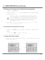
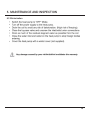
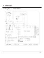
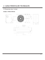
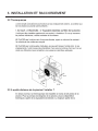
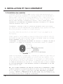
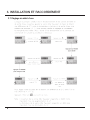
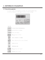
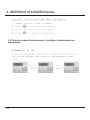
1
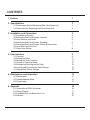
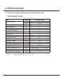
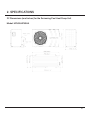
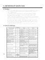
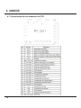
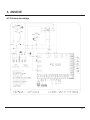
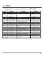
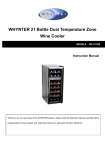
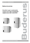
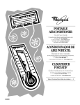
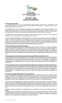
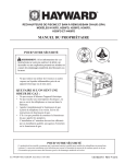
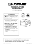
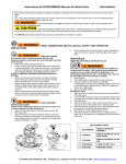
SWIMMING POOL HEAT PUMP UNIT
Installation & Instruction Manual
Models
Hayward Pool Products
620 Division St., Elizabeth, NJ 07207
www.hayward.com / 1-888-HAYWARD
HP50A
HP50HA
Hayward Canada, Inc.
2880 Plymouth Dr., Oakville, ON L6H 5R4
www.haywardpool.ca / 1-888-238-7665
CONTENTS
1. Preface1
2. Specifications2
2.1 Performance Data of Swimming Pool Heat Pump Unit
2.2 Dimensions for Swimming Pool Heat Pump Unit
2
3
3. Installation and Connection4
3.1 Installation of System4
3.2 Swimming Pool Heat Pumps: Location
5
3.3 How Close to your Pool?5
3.4 Swimming Pool Heat Pumps: Plumbing
6
3.5 Swimming Pool Heat Pumps: Electrical Connection
7
3.6 Initial Start-Up of the Unit7
3.7 Water Flow Setting8
4. User Interface9
4.1 Overview9
4.2 Setting the Clock11
4.3 Setting the Timer Function11
4.4 Choice of Operating Mode12
4.5 Settings and Viewing the Set Point
13
4.6 Locking and Unlocking the Touch Screen
13
4.7 Temperature Display Change13
5. Maintenance and Inspection14
5.1 Maintenance14
5.2 Troubleshooting Guide14
5.3 Winterization15
6. Appendix16
6.1 Connection of PCB: Illustration16
6.2 Wiring Diagram17
6.3 Exploded View and Spare Parts List
18
6.4 Warranty20
1. PREFACE
In order to provide our customers with quality, reliability and versatility, this product has
been made to strict production standards. This manual contains installation, service and
maintenance. Please read this manual carefully before you open or maintain the unit. The
manufacturer of this product will not be held responsible if someone is injured or the unit
is damaged as a result of improper installation, service or unnecessary maintenance. It is
vital that the instructions within this manual are adhered to at all times. The unit must be
installed by qualified personnel.
The unit can only be repaired by qualified installer center personnel or an authorized
dealers (HVAC).
• Maintenance and operation must be carried out according to the recommended time
and frequency, as stated in this manual.
• Use genuine standard spare parts only.
• Failure to comply with these recommendations will invalidate the warranty.
• The Swimming Pool Heat Pump Unit heats the swimming pool water and keeps the temperature constant.
This type of heat pump has the following characteristics:
1. Durable
The heat exchanger is made of PVC & titanium; the tube can withstand prolonged exposure to corrosives such as chlorine.
2. Quiet operation
The unit contains efficient rotary compressor and a low noise fan motor, which assures
its quiet operation
3. Electronic control board
The unit is controlled by an internal micro-controller, allowing all operation parameters to
be set. Operation status can be displayed on the control panel.
1
2. SPECIFICATIONS
2.1 Performance Data of Swimming Pool Heat Pump Unit
*** REFRIGERANT: R410A
Unit
Heating Capacity
Heating Power Input
Running Current
Power Supply
Compressor Quantity
Compressor(s)
Fan Quantity
Fan Power Input
Fan Rotate Speed
Fan Direction
Noise (at 1 meter)
Water Connection
Water Flow Volume Imperial/US
Water Pressure Drop (max)
Unit Net Dimensions (L/W/H)
Unit Shipping Dimensions (L/W/H)
Net Weight/Shipping Weight
Heating:
2
Model
kW
BTU/h
kW
A
V/Hz
W
RPM
dB(A)
inch
3
m /h/gpm
kPa/psi
mm/in
mm
kg/lbs
HP50A/HP50HA
14.7
45,000
2.68
12
208-230V~/60Hz
1
Rotary
1
120
850
Horizontal
54
1.5
4.5 / 20
10 / 1.5
1053x420x650 / 41.5x16.5x25.6
1110x470x670 / 43.7x18.5x26.4
58 / 128
Ambient temp (DB/WB): 75ºF (24ºC) / 66ºF (19ºC)
Water temp (in/out): 79ºF (26ºC) / 82ºF (28ºC)
2. SPECIFICATIONS
2.2 Dimensions (mm/inches) for the Swimming Pool Heat Pump Unit
Model: HP50A/HP50HA
3
3. INSTALLATION AND CONNECTION
3.1 Installation Illustration
4
3. INSTALLATION AND CONNECTION
3.2 Swimming Pool Heat Pumps: Location
3.3 How Close To Your Pool?
Normally, the pool heat pump is installed within 24.6ft (7.5 metres) of the pool. The longer
the distance from the pool, the greater the heat loss from the piping.
5
3. INSTALLATION AND CONNECTION
3.4 Swimming Pool Heat Pumps: Plumbing
The titanium heat exchanger requires no special plumbing except bypass (please set the flow
rate according to the nameplate). The water pressure drop is less than 1.5psi (10KPa) at maximum flow rate. Since there are no residual heat or flame temperatures, the unit does not need
copper heat sink piping. PVC pipes can be run straight into the unit.
Location: connect the unit in the pool pump discharge (return) line downstream of all filter and
pool pumps, and upstream of any chlorinators, ozonators or chemical pumps. Install the rubber
feet onto the bottom of the unit.
*You will need to use 1½” male PVC adapter to connect to the heat pump.
Consider adding a quick coupler fitting at the unit inlet and outlet to allow easy draining of the
unit for winterizing and to provide easier access should servicing be required (coupler supplied
with unit).
Condensation: since the heat pump cools the air down about 4-5ºC water may condense on
the fins of the horseshoe shaped evaporator. If the relative humidity is
very high, this could be as much as several gallons/litres an hour. Verify the unit is level so that
water will run down the fins into the basepan and drain out through the barbed plastic condensation drain fitted on the side of the basepan. This fitting is designed to accept 3/4” clear vinyl
tubing and run to a suitable drain. It is easy to mistake the condensation for a water leak inside
the unit.
NB: a quick way to verify that the water is condensation is to shut off the unit and keep the
pool pump running. If the water stops running out of the basepan, it is condensation. An EVEN
QUICKER WAY IS TO TEST THE DRAIN WATER FOR CHLORINE - if there is no chlorine present, then it’s condensation.
6
3. INSTALLATION AND CONNECTION
3.5 Swimming Pool Heat Pumps: Electrical Connection
3.6 Initial Start-Up
7
3. INSTALLATION AND CONNECTION
3.7 Water Flow Setting
While the heat pump is running and the water inlet and outlet valves are open, adjust the bypass valve to obtain a difference of 2ºC between the water inflow and outflow temperatures (see
Functional Diagram Section 3.1). You can check the setting by viewing the inflow (T02)/outflow
(T03) temperatures directly on the control panel by following the procedure below.
Then adjust the by-pass to obtain a difference of 2ºC between T03 and T02
8
4. USER INTERFACE
4.1 Overview
9
4. USER INTERFACE (continued)
OFF Mode
When the heat pump is on standby (OFF Mode), the time and operating mode
are displayed on the control screen.
10
4. USER INTERFACE (continued)
4.2 Setting the Clock
4.3 Setting the Timer Function
11
4. USER INTERFACE (continued)
4.4 Choice of Operating Mode: Heating, Cooling or Automatic
12
4. USER INTERFACE (continued)
4.5 Settings and viewing the set point (Desired water temperature)
4.6 Locking and unlocking the touch screen
4.7 Temperature Display Change
13
5. MAINTENANCE AND INSPECTION
5.1 Maintenance
• Check the water supply device and the release often. You should avoid the condition of no water or air entering into
the system as this will influence the unit’s performance and reliability. You should clear the pool/spa filter regularly to
avoid damage to the unit as a result of a clogged filter.
• The area around the unit should be dry, clean and well ventilated. Clean the side heating exchanger regularly to
maintain good heat exchange and conserve energy. Do not pressure wash or use undue force in cleaning as this
may damage fins and reduce efficiency and capacity of heat pump.
• The operation pressure of the refrigerant system should only be serviced by a certified technician.
• Check the power supply and cable connection often. Should the unit begin to operate abnormally, switch it off and
contact your qualified technician.
• Discharge all water in the water pump and water system so that freezing of the water-inlet the pump or water
system does not occur. You should discharge the water at the bottom of the water pump if the unit will not be used
for an extended period of time. You should check the unit thoroughly and fill the system with water fully before
using it for the first time after a prolonged period of no usage.
• Installation must be performed in accordance with the NEC/CEC by authorized person only.
5.2 Troubleshooting Guide
14
5. MAINTENANCE AND INSPECTION
5.3 Winterization
15
6. APPENDIX
6.1 Connection of PCB Illustration
16
6. APPENDIX
6.2 Wiring Diagram - HP50A/HP50HA
17
6. APPENDIX
6.3 Exploded View and Spare Parts
18
6. APPENDIX
6.3 Spare Parts List & Spare Parts - HP50A/HP50HA
SN
1
2
3
4
5
6
7
8
9
10
11
12
13
14
15
16
17
18
19
20
21
Part Code
32012-120020
20000-220188
20000-330124
3500-2701
2001-1418
20000-110041
20000-360005
32012-120014
2001-3605
32012-220044
32012-220045
2001-3907
2000-2111
20000-350012
95005-310188
35005-310145
2000-3603
2000-3505
20000-360006
20000-140153
2000-3242
Part Name
Evaporator
Fan Net
Fan Motor
Axis Blower Fan
4 Way Valve
Compressor
Water Flow Switch
Titanium Tube Heat Exchanger
High Pressure Switch
Front Panel
Cover
Terminal
Water proof cover
Fan Capacitor
LCD Controller
Main Control Board
Low Pressure Switch
Compressor Capacitor
AC Contactor
Needle Valve
Sensor, water, air
Part Number
HPX32012-120020
HPX20000-220188
HPX20000-330124
HPX3500-2701
HPX2001-1418
HPX20000-110041
HPX20000-360005
HPX32012-120014
HPX2001-3605
HPX32012-220044
HPX32012-220045
HPX2001-3907
HPX2000-2111
HPX20000-350012
HPX95005-310188
HPX35005-310145
HPX2000-3603
HPX2000-3505
HPX20000-360006
HPX20000-140153
HPX2000-3242
19
6. APPENDIX
6.4 Warranty
THERMOPOMPE POUR PISCINE
Manuel d’instructions et d’installation
Modèle
Hayward Pool Products
620 Division St., Elizabeth, NJ 07207
www.hayward.com / 1-888-HAYWARD
HP50A
HP50HA
Hayward Canada, Inc.
2880 Plymouth Dr., Oakville, ON L6H 5R4
www.haywardpool.ca / 1-888-238-7665
SOMMAIRE
1. Préface1
2. Caractéristiques techniques2
2.1 Données techniques de la pompe à chaleur
2
2.2 Dimensions3
3. Installation et raccordement4
3.1 Illustration de lìnstallation4
3.2 Thermopompe5
3.3 A quelle distance de la piscine l’installer
5
3.4 Installation des conduites6
3.5 Raccordement électrique7
3.6 Premier démarrage7
3.7 Réglage du debit d’eau8
4. Interface Utilisateur9
4.1 Présentation générale9
4.2 Réglage de l’horloge11
4.3 Réglage de la fonction timer11
4.4 Choix du mode de fonctionnement12
4.5 Réglage et visualisation du point de consigne
13
4.6 Verrouillage et déverrouillage de l’écran tactile
13
4.7 Charger la température sur l’affichage
13
5. Entretien et inspection14
5.1 Entretien14
5.2 Guide de dépannage14
5.3 Hivernage15
6. Annexe16
6.1 Schématique de raccordement du PCB
16
6.2 Schéma de câblage17
6.3 Vue éclatée et liste des pièces
18
6.4 Garantie20
1. PREFACE
1
2. CARACTERISTIQUES TECHNIQUES
2.1 Données techniques de la thermopompe
*** REFRIGERANT: R410A
Unit
Capacité calorifique
Puisssance calorifique à l’entrée
Courant de fonctionnement
Alimentation électrique
Modèle
kW
BTU/h
kW
A
V/Hz
Nombre de compresseurs
Type de compresseur
Nombre de ventilateurs
Puissance du ventilateur
Vitesse de rotation du ventilateur
W
RPM
Direction du ventilateur
Niveau de pression sonore (à 1 mètre)
Raccordement hydraulique
Débit d’eau
Perte de charge sur l’eau (max)
Dimensions nettes de l’unité (L/l/h)
Dimensions de l’unité emballée (L/l/h)
Poids net/poids de l’unité emballée
Chauffage:
2
dB(A)
inch
3
m /h/gpm
kPa/psi
mm/in
mm/in
kg/lb
HP50A
14,7
45 000
2,68
12
208-230V~/60Hz
1
Rotatif
1
120
850
Horizontale
54
1,5
4,5 / 20
10 / 1,5
1053x420x650 / 41.5x16.5x25.6
1110x470x670 / 43.7x18.5x26.4
58 / 128
Température Ambiante (BS/BM): 24ºC (75ºF) / 19ºC (66ºF)
Temérature de l’eau (entrer/sortie): 26ºC (79ºF) / 28ºC (82ºF)
2. CARACTERISTIQUES TECHNIQUES
2.2 Dimensions (mm / inches)
Modèle: HP50A/HP50HA
3
3. INSTALLATION ET RACCORDEMENT
3.1 Illustration de l’installation
4
3. INSTALLATION ET RACCORDEMENT
3.2 Thermopompe
3.3 A quelle distance de la piscine l’installer ?
5
3. INSTALLATION ET RACCORDEMENT
3.4 Installation des conduites
6
3. INSTALLATION ET RACCORDEMENT
3.5 Raccordement électrique
3.6 Premier démarrage
7
3. INSTALLATION ET RACCORDEMENT
3.7 Réglage du débit d’eau
8
4. INTERFACE UTILISATEUR
4.1 Présentation générale
9
4. INTERFACE UTILISATEUR (suite)
10
4. INTERFACE UTILISATEUR (suite)
4.2 Réglage de l’horloge
4.3 Réglage de la fonction timer
11
4. INTERFACE UTILISATEUR (suite)
4.4 Choix du mode de fonctionnement : chauffage, refroidissement ou
automatique
12
4. INTERFACE UTILISATEUR (suite)
4.5 Réglage et visualisation du point de consigne (Température d’eau
souhaitée)
4.6 Verrouillage et déverrouillage de l’écran tactile
4.7 Charger température sur l’affichage
13
5. ENTRETIEN ET INSPECTION
5.1 Entretien
5.2 Guide de dépannage
14
5. ENTRETIEN ET INSPECTION
5.3 Hivernage
15
6. ANNEXE
6.1 Schématique de raccordement du PCB
16
6. ANNEXE
6.2 Schéma de cablage
17
6. ANNEXE
6.3 Vue éclatée
18
6. ANNEXE
6.3 Liste des pièces principales et pièces détachées - HP50A/HP50HA
SN
1
2
3
4
5
6
7
8
9
10
11
12
13
14
15
16
17
18
19
20
21
Part Code
32012-120020
20000-220188
20000-330124
3500-2701
2001-1418
20000-110041
20000-360005
32012-120014
2001-3605
32012-220044
32012-220045
2001-3907
2000-2111
20000-350012
95005-310188
35005-310145
2000-3603
2000-3505
20000-360006
20000-140153
2000-3242
Part Name
Evaporateur
Plastique de protection du ventilateur
Moteur de ventilateur
Ventilateur axial
Vanne 4 voies
Compresseur
Détecteur de debit d’eau
Echangeur de chaleur en Titane
Pressostat haute pression
Panneau de façade
Couvercle
Bornier
Couvercle étanche
Condensateur de ventilateur
Unité de commande de l’ACL
Carte de contôle
Pressostat basse pression
Condensateur du compresseur
AC Contacteur
Vanne à aiguille
Capteur (d’eau et de l’air)
Part Number
HPX32012-120020
HPX20000-220188
HPX20000-330124
HPX3500-2701
HPX2001-1418
HPX20000-110041
HPX20000-360005
HPX32012-120014
HPX2001-3605
HPX32012-220044
HPX32012-220045
HPX2001-3907
HPX2000-2111
HPX20000-350012
HPX95005-310188
HPX35005-310145
HPX2000-3603
HPX2000-3505
HPX20000-360006
HPX20000-140153
HPX2000-3242
19
6. ANNEXE
6.4 Garantie
Hayward Pool Products
620 Division St., Elizabeth, NJ 07207
www.hayward.com / 1-888-HAYWARD
Hayward Canada, Inc.
2880 Plymouth Dr., Oakville, ON L6H 5R4
www.haywardpool.ca / 1-888-238-7665