1
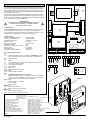
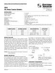
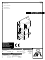
I
D811224
06-06-98
Ver. 01
CENTRALINA DI COMANDO
GB CONTROL UNIT
F
UNITÉ DE COMMANDE
D
STEUERZENTRALE
E
CENTRAL DE MANDO
ELMEC2
ISTRUZIONI
INSTRUCTIONS
INSTRUCTIONS
MONTAGEANLEITUNG
INSTRUCCIONES
BFT
U.K.
SWIFT Automation Ltd
Hindley Street, Stockport
SK1 3LF England
Tel.
0 161 480 6677
Fax.
0 161 477 6675
BFT
FRANCE
Parc Club des Aygalades
35 bd capitaine GEZE
13333 MARSEILLE Cedex 14
Tel.
Fax
04 91.98.13.82
04 91.98.11.27
BFT
DEUTSCHLAND
Vertretung und Lager
Johannisstr. 14,D-90763 Fürth
Tel.
Fax
BFT
0049 911 773323
0049 911 773324
ESPAÑA
BERMATIC BFT S.L.
Poligono GARONA NAVE Q
19200 AZUQUECA DE
HENARES (GUADALAJARA)
Tel.
949/263200
Fax
949/262451
BFT S.r.l.
ITALIA
Via Lago di Vico, 44
36015 SCHIO (VICENZA)
Tel. naz.
(0445) 696511
Tel. int.
+39 (445) 696533
Fax
(0445) 696522
INTERNET
www.bft.it
E-MAIL
[email protected]
I
GB
Nel ringraziarVi per la preferenza accordata a questo prodotto, la ditta è certa che
da esso otterrete le prestazioni necessarie al Vostro uso.
Leggete attentamente l’opuscolo ”Libretto istruzioni” che lo accompagna in quanto esso fornisce importanti indicazioni riguardanti la sicurezza, l’installazione, l’uso
e la manutenzione.
Questo prodotto risponde alle norme riconosciute della tecnica e delle disposizioni relative alla sicurezza.
Confermiamo che esso è conforme alle seguenti direttive europee: 89/336/CEE,
73/23/CEE (modificata da RL 91/263/CEE, 92/31/CEE e 93/68/CEE).
Thank you for buying this product, our company is sure that you will be more than
satisfied with the product’s performance.
The product is supplied an “INSTRUCTION MANUAL” which provides important
information about safety, installation, operation and maintenance.
This product complies with the recognised technical standards and safety regulations.
We declare that this product is in conformity with the following European Directives: 89/336/EEC and 73/23/EEC (amended by RL 91/263/EEC, 92/31/EEC and
93/68/EEC).
AVVERTENZE
Nelle operazioni di cablaggio ed installazione riferirsi alle
norme vigenti e comunque ai principi di buona tecnica.
IMPORTANT NOTE
For wiring and installation operations, refer to the
current standards and follow the main technical principles
ensuring good performance.
1) Generalità
ELMEC2 è adatta a controllare un motore trifase fino a 750 W di potenza.
La centralina è dotata di Dip-FIX che ne consentono la configurazione.
Le funzioni dei Dip-FIX vengono spiegate nei paragrafi seguenti e il collegamento
ai morsetti è illustrato dallo schema di figura 1.
2) Dati tecnici
Tensione di alimentazione trifase
Isolamento rete/bassa tensione
Rigidità dielettrica rete/bt
Corrente a vuoto
Alimentazione accessori
Corrente max relè
Potenza max assorbita dal motore
Finecorsa
Dimensione quadro
Temperatura di utilizzo
400V±10% 50Hz.
> 2MOhm 500Vdc
3750Vac per 1 minuto
0.05A max
24Vac 8VA max
1.6A
750W
contatto N.C.
183x225x120
-20/+55 °C
3) Collegamento morsettiera
JP1
1-2-3 Alimentazione trifase: 400V ±10% 50/60 Hz. Attenzione: prevedere il
sezionamento della linea a monte e 3 fusibili da 2A.
4-5-6 Collegamenti motore
JP3
7
Comune
7-8
Pulsante di STOP (N.C.). In caso di non utilizzo, lasciare ponticellato.
7-9
Finecorsa apertura (SWO)
7-10
Finecorsa chiusura (SWC)
9-11
Pulsante apertura
10-12 Pulsante chiusura
13-14 Uscita 24Vac 0.3A max (8VA)
JP4 (opzionale)
15-16 Antenna (15 segnale, 16 calza)
JP2
17-18 ATTENZIONE: Tensione di rete ai morsetti
Pulsante di EMERGENZA (N.C.). Utilizzare un pulsante di arresto con
ritenuta e con due contatti N.C. con almeno 8 mm di distanza in aria.
In caso di non utilizzo, lasciare ponticellato.
JP5 (opzionale)
Connettore ricevente 1-2 canali.
Canale 1 - Apre (opzionale)
Canale 2 - Chiude
DIP-FIX J1
ON
Comando chiusura automatica.
OFF
Comando chiusura ad uomo presente.
DIP-FIX J2
ON
Comando apertura automatica.
OFF
Comando apertura ad uomo presente.
2 - ELMEC2
1) General outline
The ELMEC2 control unit has been designed to control one three-phase motor
with a power up to 750 W.
The control unit is equipped with Dip-FIX which allow configuration of the unit.
The functions of the Dip-FIX are described in the following paragraphs while the
connection to the terminals is shown in the diagram of fig. 1.
2) Technical specifications
Three-phase main power supply
Mains insulation/low voltage
Dielectric strength/low voltage
No-load current
Power supply to accessories
Relay max current
Max power absorbed by motor
Limit switches
Control board dimensions
Working temperature
400V±10% 50Hz.
> 2MOhm 500Vdc
3750Vac per 1 minute
0.05A max
24Vac 8VA max
1.6A
750W
N.C. contact
183x225x120
-20/+55 °C
3) Terminal board connection
JP1
1-2-3 Three-phase power supply: 400V ±10% 50/60 Hz. WARNING: break the
line upstream and fit three 2A fuses.
4-5-6 Motor connections
JP3
7
Common wire
7-8
STOP push button (N.C.). If not used, leave jumped.
7-9
Opening limit switch (SWO)
7-10
Closing limit switch (SWC)
9-11
Opening push button
10-12 Closing push button
13-14 Output 24Vac 0.3A max (8VA)
JP4 (on request)
15-16 Antenna (15 signal, 16 braid)
JP2
17-18 WARNING: Mains current to terminals
EMERGENCY push button (N.C.). Use a stop hold-to-run push button
and two N.C. contacts having at least 8 mm air distance. If not used,
leave jumped.
JP5 (on request).
1-2 channel receiver connector.
Channel 1 - Opens
Channel 2 - Closes
DIP-FIX J1
ON
Automatic closing control.
OFF
Hold-to-run closing control.
DIP-FIX J2
ON
Automatic opening control.
OFF
Hold-to-run opening control.
F
D
Nous vous remercions pour avoir choisi ce produit. Nous sommes certains qu’il
vous offrira les performances que vous souhaitez.
Lisez attentivement le “Manuel d’instructions” qui accompagne ce produit, puisqu’il fournit d’importantes indications concernant la sécurité, l’installation, l’utilisation et l’entretien.
Ce produit est conforme aux règles reconnues de la technique et aux dispositions
de sécurité. Nous certifions sa conformité avec les directives européennes suivantes: 89/336/CEE, 73/23/CEE (amendée par les directives RL 91/263/CEE,
92/31/CEE et 93/68/CEE).
Wir danken Ihnen, daß Sie sich für diese Anlage entschieden haben. Sicherlich
wird sie mit ihren Leistungen Ihren Ansprüchen gerecht werden.
Lesen Sie aufmerksam die beiliegende Broschüre “GEBRAUCHSANWEISUNGEN” durch. Sie enthält wichtige Hinweise zur Sicherheit, Installation, Bedienung
und Wartung der Anlage.
Dieses Produkt genügt den anerkannten technischen Normen und Sicherheitsbestimmungen. Wir bestätigen, daß es mit folgenden Europäischen Richtlinien
übereinstimmt: 89/336/EWG, 73/23/EWG (geändert durch RL 91/263/EWG, 92/
31/EWG und 93/68/EWG).
AVERTISSEMENTS
Pour les opérations de câblage et d’installation, se référer
aux normes en vigueur et aux principes de bonne technique.
HINWEISE
Bei Verkablung und Installation halten Sie sich bitte an die
geltenden Vorschriften und anerkannten technischen Regeln
1) Généralités
La centrale ELMEC2 est indiquée pour commander un moteur triphasé jusqu’à
750 W de puissance.
La centrale est dotée de Dip-FIX qui en permettent la configuration.
Les fonctions des Dip-FIX sont expliquées aux paragraphes suivants et la connexion aux bornes est illustrée dans le schéma de la figure 1.
1) Allgemeine Informationen
ELMEC2 ist zur Kontrolle von Drehstrommotoren bis zu einer Leistung von 750W
ausgelegt.
Die Steuerung wird über Dip-FIX konfiguriert. Die einzelnen Funktionen der DipFIX werden in den folgenden Abschnitten erläutert. Der Anschluß an die Klemmen wird durch die schematische Darstellung in Abbildung 1 verbildlicht.
2) Caractéristiques techniques
Tension d’alimentation triphasée
Isolement ligne/basse tension
Rigidité diélectrique ligne/bt
Courant à vide
Alimentation des accessoires
Courant maxi relais
Puissance maxi absorbée par le moteur
Fin de course
Dimensions du tableau
Température d’utilisation
2) Technische Daten
Versorgungsspannung Drehstrom
Netzisolierung/Niederspannung
Netzdurchschlagsfestigkeit /Niederspannung
Leerlaufstrom
Speisung Zubehör
Max. Relaisstrom
Max. Leistungsaufnahme des Motors
Endschalter Öffnung-Schließung
Gehäuseabmessungen
Betriebstemperatur
400V±10% 50Hz (triphasé).
> 2MOhm 500Vdc
3750Vac pendant 1 minute
0,05A maxi
24Vac 8VA maxi
1,6A
750W
contact N.F.
183x225x120
-20/+55 °C
3) Connexion bornier
JP1
1-2-3 Alimentation triphasée 400V ±10% 50/60 Hz. ATTENTION: prévoir la
disjonction de la ligne en amont et 3 fusibles de 2 A.
4-5-6 Connexions moteur
JP3
7
Commun
7-8
Bouton de STOP (N.F.).
En cas de non utilisation, il faut laisser le pontet inseré.
7-9
Fin de course ouverture (SWO)
7-10
Fin de course fermeture (SWC)
9-11
Bouton ouverture
10-12 Bouton fermeture
13-14 Sortie 24Vac 0,3A maxi (8VA)
JP4 (en option)
15-16 Antenne (15 signal, 16 gaine)
JP2
17-18 ATTENTION: Tension de ligne aux bornes
Bouton d’URGENCE (N.F.). Utiliser un bouton de stop à action maintenue et deux contacts N.F. avec au moins 8 mm de distance en l’air.
En cas de non utilisation, il faut laisser le pontet inserè.
JP5 (en option)
Connecteur récepteur 1-2 canaux
Canal 1 - Ouvre
Canal 2 - Ferme
DIP-FIX J1
ON
Commande fermeture automatique
OFF
Commande fermeture à action maintenue
DIP-FIX J2
ON
Commande ouverture automatique
OFF
Commande ouverture à action maintenue
400 V±10% 50Hz.
> 2MOhm 500Vdc
3750Vac pro Minute
0.05A max
24Vac 8VA max
1,6 A
750W
Ruhekontakt (N.C.)
183x225x120
-20/+55 °C
3) Anschluß des Klemmbrettes
JP1
1-2-3 Drehstrom: 400V ±10% 50/60 Hz. ACHTUNG: Bringen Sie am Anfang
der Leitung eine Trennvorrichtung und 3x2 Amp. Sicherungen an.
4-5-6 Motoranschlüsse
JP3
7
Gemeinsam
7-8
STOP -Knopf (N.C.). Falls nicht verwendet, überbrückt lassen.
7-9
Endschalter Öffnung (SWO)
7-10
Endschalter Schließung (SWC)
9-11
Druckknopf Öffnung
10-12 Druckknopf Schließung
13-14 Ausgang 24Vac 0.3A max (8VA)
JP4 (Sonderausstattung)
15-16 Antenne (15 Signal, 16 Abschirmung)
JP2
17-18 ACHTUNG: Klemmen stehen unter Netzspannung
NOT-AUS-Knopf (N.C.). Einen Not-Knopf mit Rückhaltemechanik und
zwei Ruhekontakten (Öffner) mit mind. 8mm Luftabstand voneinander.
Falls nicht verwendet, überbrückt lassen.
JP5 (Sonderausstattung).
Steckverbinder 1-2-Kanal-Empfänger.
Kanal 1 - Öffnen
Kanal 2 - Schließen
DIP-FIX J1
ON
Definierter ZU - Befehl.
OFF
ZU in Totmannfunktion.
DIP-FIX J2
ON
Definierter AUF - Befehl.
OFF
AUF in Totmannfunktion.
ELMEC2 - 3
T1
E
La empresa le agradece la preferencia que ha manifestado por este producto y
está segura de que de él obtendrá las prestaciones necesarias para sus exigencias. Lea atentamente el ”Manual de instrucciones” que lo acompaña, pues proporciona importantes indicaciones referentes a la seguridad, la instalación, el uso
y el mantenimiento del mismo.
Este producto cumple los requisitos establecidos por las normas reconocidas de
la técnica y las disposiciones relativas a la seguridad. Confirmamos su conformidad con las siguientes directivas europeas: 89/336/CEE, 73/23/CEE (modificada
por RL 91/263/CEE, 92/31/CEE y 93/68/CEE).
Cavallotto di messa a terra
U-link for earth connection
Crampillon de mise à la terre
Erdanschlussklemmen
Perno de U de toma de tierra
La centralina viene fornita completa
di cablaggi e pulsanti su coperchio di
OPEN - CLOSE - STOP.
The control unit is supplied with cables
and OPEN - CLOSE - STOP push
buttons on the cover.
La centrale est fournie équipée de
câblage et de boutons sur le couvercle
de OPEN - CLOSE - STOP.
Die Steuerung wird komplett mit verkabelten
OPEN - CLOSE - STOP Taster geliefert.
La central se suministra provista de cableados
y botones en la tapa de OPEN - CLOSE - STOP.
Fig.1
4 - ELMEC2
K4
F1
K1
JP4
K3
ELMEC2
OFF Open D. M.
ON Open
J2
J2
J1
OFF Close D. M.
J1
ON Close
JP2
JP3
3
4
5
6
7
T
M
JP2
17 18
STOP
JP4
15 16
ANT.
Disponibilità di raccordi tubo - cassetta:
CRTR (raccordo con tubo rigido)
CRTL (raccordo con guaina flessibile)
Available couplings connecting the pipes to the box:
CRTR (coupling with rigid pipe)
CRTL (coupling with flexible sheath)
Disponibilité de raccords tube - boîte:
CRTR (raccord avec tube rigide)
CRTL (raccord avec tuyau souple)
Erhältliche Rohrverschraubungen für Steuerungsgehäuse:
CRTR (Verbindungsstück für starres Rohr)
CRTL (Verbindungsstück für flexibles Rohr)
Disponibilidad de uniones tubo - caja:
CRTR (unión con tubo rígido)
CRTL (unión con vaina flexible)
6
7
8
9
9
10 11 12 13 14
10 11 12 13 14
SWC
S
5
SWO
R
4
COM
3
2
STOP
1
8
JP3
JP1
OPEN
2
CLOSE
1
24Vac
NO NO
NC NC NC
EMERGENCY
3) Conexión tablero de bornes
JP1
1-2-3 Alimentación trifásica: 400V ±10% 50/60 Hz. ATENCION: es preciso
prever el seccionamiento de la línea al principio y 3 fusibles de 2A.
4-5-6 Conexiones motor
JP3
7
Común
7-8
Botón de STOP (N.C.). En caso de no utilización, déjese puenteado.
7-9
Fin de carrera apertura (SWO)
7-10
Fin de carrera cierre (SWC)
9-11
Botón apertura
10-12 Botón cierre
13-14 Salida 24Vac 0,3A máx. (8VA)
JP4 (opcional)
15-16 Antena (15 señal, 16 trenza)
JP2
17-18 ATENCION: Tensión de red en los bornes
Botón de EMERGENCIA (N.C.). Debe utilizarse un botón de parada con
retención y con dos contactos N.C. con al menos 8 mm de distancia en
el aire. En caso de no utilización, déjese puenteado.
JP5 (opcional).
Conector receptor 1-2 canales
Canal 1 - Abre
Canal 2 - Cierra
DIP-FIX J1
ON
Mando cierre automático.
OFF
Mando cierre con hombre presente.
DIP-FIX J2
ON
Mando apertura automática.
OFF
Mando apertura con hombre presente.
18
K1
400V±10% 50Hz.
> 2MOhm 500Vdc.
3.750Vac por 1 minuto.
0,05A máx.
24Vac 8VA máx.
1,6A
750W
contacto N.C.
183x225x120
-20/+55 °C
17
JP1
2) Datos técnicos
Tensión de alimentación trifásica
Aislamiento red/baja tensión
Rigidez dieléctrica red/bt
Corriente en vacío
Alimentación accesorios
Corriente máx. relés
Potencia máx. absorbida por el motor
Fines de carrera
Dimensiones cuadro
Temperatura de funcionamiento
230V T 0.1A
ADVERTENCIAS
En las operaciones de cableado e instalación, ténganse en
cuenta las normas vigentes y, en cualquier caso, los
principios de buena técnica.
1) Generalidades
La central ELMEC2 puede controlar un motor trifásico de hasta 750 W de potencia. La central está dotada de Dip-FIX, que permiten su configuración.
Las funciones de los Dip-FIX se explican en los apartados siguientes y la conexión a los bornes está ilustrada en el esquema de la figura 1.
JP5
DL1
Dip-Fix: ON
Dip-Fix: OFF
ELMEC2
OP
ST
E
OS
CL
EN
OP