1
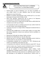
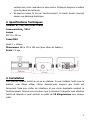
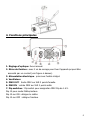
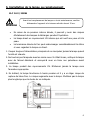
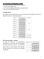
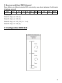
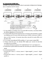
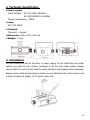
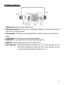
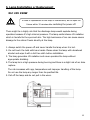
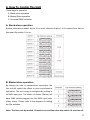
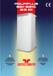
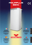
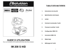
1 SOMMAIRE 1. Instructions de sécurité 2. Spécifications techniques 3. Installation 4. Fonctions principales 5. Installation ou Remplacement de la lampe 6. Comment contrôler l'unité 7. Configuration DMX 512 8. Connection DMX 512 9. Nettoyage 2 1. Instructions de sécurité LISEZ CES INSTRUCTIONS AVANT LA PREMIERE WARNING • UTILISATION ET A CHAQUE MAINTENANCE Veuillez garder ce manuel d'utilisateur pour une future consultation. Si vous vendez l'unité à un autre utilisateur, soyez sûr qu'ils reçoivent également ce livret d'instruction. • Déballez et contrôlez soigneusement l'unité, vérifiez qu'il n'y a eu aucun • Avant toute opération, assurez-vous que la tension et la fréquence dommage de transport avant d'utiliser l'unité. correspondent à l'alimentation électrique de l'unité. • L'unité est conçue pour un usage avec une MSD 250W ou NSD 250W. Elle n'emploie aucun autre type de lampe. • Il est important de relier le conducteur jaune/vert pour mettre l'unité à la terre afin d'éviter toute décharge électrique. • L'unité est conçue pour un usage intérieur. Employez-la seulement dans un endroit sec. • L'unité doit être installée dans un endroit ayant ventilé, à au moins 50cm des surfaces adjacentes. Assurez-vous qu'aucune fente de ventilation ne soit bloquée. • Débranchez l'unité avant de changer fusible ou lampe. • Remplacez les fusible/lampe par ceux de même type. • Assurez-vous qu'il n'y ait aucun matériau inflammable près de l'unité en fonctionnement car ceci peut être un risque d'incendie. • La température ambiante est au maximum TA : 40°C. N'actionnez pas l'unité à une température plus élevée que cela. • La température de surface de l'unité peut atteindre jusqu'à 80°C. Ne pas toucher à mains nues. Coupez le courant et attendez environ 15 minutes pour que l'unité refroidisse avant de remplacer l'ampoule. • En cas de problème de fonctionnement, cessez d'utiliser l'unité immédiatement. N'essayez jamais de réparer l'unité par vous-même. les réparations effectuées par les personnes non qualifiées peuvent mener à des dommages ou des défauts de fonctionnement. Veuillez entrer en 3 contact avec votre revendeur le plus proche. Employez toujours le même type de pièces de rechange. • Ne touchez aucun fil lors du fonctionnement. La haute tension pourrait causer une décharge électrique. 2. Specifications Techniques Tension: AC 230/240/250V~50Hz Consommation:250W Lampe ELC 24 v 250 w Canal DMX Canal 1 = vitesse Dimensions: 285 x 275 x 200 mm (avec étrier de fixation) Poids: 7,3 kgs 3. Installation Vous pouvez installer l'unité au sol ou au plafond. Si vous installez l'unité sous le plafond, vous devez utiliser l'étrier. Assurez-vous toujours que l'unité est fermement fixée pour éviter les vibrations et une chute éventuelle pendant le fonctionnement. Assurez-vous toujours que la structure à laquelle vous attachez l'unité est bloquée et peut soutenir un poids de 10 kilogrammes pour chaque unité. 4 4. Fonctions principales 1. Réglage d'optique: focus manuel. 2. Etrier de fixation : avec 2 vis de serrage pour fixer l’appareil qui peut être accroché par un crochet (voir figure ci-dessus). 3. Alimentation électrique:prise avec fusible intégré. 4. Ventilateur 5. DMX OUT:Sortie DMX sur XLR 3 points femelle. 6. DMX IN:entrée DMX sur XLR 3 points mâle 7. Dip switches:Dip switch pour assignation DMX Dip de 1 à 9. Dip 10 pour mode Maître/esclave Dip 10 sur ON : désigne le maître Dip 10 sur OFF : désigne l'esclave 5 5. Installation de la lampe ou remplacement ELC 24 V/ 250W Avant tout remplacement de lampe ou toute maintenance, veuillez WARNING débrancher l’appareil et le laissez refroidir durant 15 mn. • En raison de sa pression interne élevée, il pourrait y avoir des risques • La lampe émet un rayonnement UV intense qui est nocif aux yeux et à la d’éclatement des lampes à décharges pendant l’opération. peau. • La luminance élevée de l'arc peut endommager considérablement la rétine si vous regardez la lampe en direct. 1. Coupez toujours l'alimentation principale et ne manipulez jamais la lampe quand l’unité est chaude. 2. Ne touchez pas l'ampoule avec les mains nues. Si c’était le cas, nettoyez la lampe avec de l'alcool dénaturé et essuyez-là avec un tissu non pelucheux avant installation. 3. La lampe produit des rayonnements UV. N’allumez jamais la lampe sans l’armature appropriée. 4. En brûlant, la lampe fonctionne à haute pression et il y a un léger risque de rupture de tube d'arc. Le risque augmente avec le temps. N'utilisez pas la lampe plus longtemps que la durée de vie indiquée. 6 6. Comment commander l'unité Vous pouvez actionner l'unité de trois manières : 1. avec le mode Stand Alone 2. par fonction intégrée master/slave préprogrammée 3. par un contrôleur DMX universel. A. Stand-alone Pour utiliser le mode Stand Alone vous devez utiliser les Dip switches à l'arrière de l'appareil comme sur le schéma suivant. B. En mode maître / esclave En liant les unités par un raccordement master/slave, la première unité commandera les autres unités pour donner une exposition légère active et synchronisée. Cette fonction est bonne quand vous voulez une utilisation instantanée. 7 C. Avec un contrôleur DMX Universel Pour utiliser une télécommande DMX universelle, vous devez adresser l'unité selon le tableau suivant: Dip #1 Value 1 • Exemples: #2 2 #3 4 #4 8 #5 16 #6 32 #7 64 #8 128 #9 256 #10 M/S Canal 1: dip / on: #1 (1) Canal 2: dip / on: #2 (2) Canal 3: dip / on: #1, #2 (1 + 2 =3) Canal 4: dip / on: #3 (4) 7. Configuration DMX 512 8 8. Connection DMX 512 Le DMX512 est employé couramment dans la commande intelligente de l'éclairage, avec un maximum de 512 canaux. 1. Si vous utilisez un contrôleur avec une sortie DMX 5 broches, vous devez utiliser des câbles adaptateurs 5/3 broches XLR. 2. Les lignes DMX doivent être terminées avec un bouchon de terminaison. Soudez une résistance de 120 ohms 1/4W entre la borne 2 (DMX-) et la borne 3 (DMX+) dans un XLR 3 broches. Ce bouchon devra être raccordé à la sortie DMX de la dernière unité. 3. Il n’y a aucun raccordement DMX possible en Y, ceci coupe le signal DMX 4. Chaque unité doit avoir une adresse DMX réglée pour recevoir les données envoyées par le contrôleur. Le nombre d'adresse est entre 0-511 (habituellement 0 et 1 sont égaux à 1). 5. l’extrémité du système DMX512 devrait être terminée pour réduire les erreurs de signal. 6. Les branchements XLR - 3 broches XLR : Borne 1 : La terre, borne 2 : Signal négatif (-), borne 3 : Signal positif (+) - 5 broches XLR : Borne 1 : La terre, borne 2 : Signal négatif (-), borne 3 : Signal positif (+) 9 9. Nettoyage du montage Le nettoyage des objectifs et/ou des miroirs optiques internes et externes doit être effectué périodiquement afin d’optimiser le rendement lumineux. La fréquence de nettoyage dépend de l'environnement dans lequel le montage fonctionne : humide, fumeux ou en particulier l'entourage sale peut causer une plus grande accumulation de la saleté sur le système optique. • Nettoyez avec un tissu ne pluchant pas en utilisant le liquide de nettoyage de verre normal. • Séchez toujours les pièces soigneusement. • Nettoyez le système optique externe au moins tout les mois. Nettoyez le système optique interne tout les 2 mois. 10 11 TABLE OF CONTENTS 1. Safety Instruction 2. Technical Specification 3. Installation 4. Main Function 5. Lamp Installation or Replacement 6. How To Control the Unit 7. DMX 512 Configuration 8. DMX 512 Connection 9. Fixture Cleaning 12 1. Safety Instruction Please read the instruction carefully which including important information about the installation, operation and maintenance. WARNING ♦ Please keep this User Manual for future consultation. If you sell the unit to another user, be sure that they also receive this instruction booklet. ♦ Unpack and check carefully there is no transportation damage before using the unit. ♦ Before operating, ensure that the voltage and frequency of power supply match the power requirements of the unit. ♦ It’s important to ground the yellow/green conductor to earth in order to avoid electric shock. ♦ The unit is for indoor use only and use only in a dry location. ♦ The unit must be installed in a location with adequate ventilation, at least 50cm from adjacent surfaces. Be sure that no ventilation slots are blocked. ♦ Disconnect mains power before fuse/lamp replacement or servicing. ♦ Replace fuse/lamp only with the same type. ♦ Make sure there are not flammable materials close to the unit while operating as it is fire hazard. ♦ Use safety cable when fixes this unit. ♦ Maximum ambient temperature is TA: 40℃ and don’t operate it where the temperature is higher than this. ♦ Unit surface temperature may reach up to 60℃. Don’t touch the housing bare-hand during its operation. Turn the power off and wait for 15 minutes for cool down before replacing bulb or serving. ♦ In the event of serious operating problem, stop using the unit immediately. Never try to repair the unit by yourself. Repair carried out by unskilled people can lead to damage or malfunction. Please contact the nearest authorized technical assistance center and always use the same type spare parts. ♦ Don’t connect the device to any dimmer pack or power pack. ♦ Do not touch any wire during operation as high voltage might be causing electric shock. 13 2. Technical Specification Power supply Input Voltage: AC 100/120V~50/60Hz AC 230/240/250V~50/60Hz Power consumption:250W Lamp ELC 24V 250W Channels Channel 1 = Speed Dimension: 285 x 275 x 200 mm Weight: 7.3 kg 3. Installation You can install the unit on the floor or under ceiling. If you install the unit under ceiling, you have to use a clamp (optional) to fix the unit under ceiling. Always ensure that the unit is firmly fixed to avoid vibration and slipping while operating. Always ensure that the structure to which you are attaching the unit is secure and is able to support a weight of 10 kgs for each unit. 14 4. Main Function 1. Optical lens: Manual focus adjustment. 2. Hanging bracket: with 2 knobs on both sides to fasten the unit and a mounting hole to fix a mounting hook. 3. Mains input:IEC socket and integrated fuse holder, connect to main power cable. 4. Cooling fan: Cool down the working temperature. 5. DMX OUT:Transmit DMX signals by XLR female socket. 6. DMX IN:Receive DMX signals by XLR male socket. 7. Dip switches:Enable DMX address setting by pin 1~9, when Dip switch 10 is off. Enable stand-alone model: pin 9 for motor direction & pins 1~8 for speed adjustable when Dip 10 is on. 15 5. Lamp Installation or Replacement ELC 24V 250W In case of replacement of the lamp or maintenance, do not open the WARNING fixture within 15 minutes after switching the power off. There might be a highly risk that the discharge lamp would explode during operation because it’s high internal pressure. The lamp emits intense UV radiation which is harmful to the eyes and skin. The high luminance of arc can cause severe damage to the retina if looks directly at the lamp. 1. Always switch the power off and never handle the lamp when it is hot. 2. Do not touch the bulb with bare hands. Please clean the lamp with denatured alcohol and wipe it with a lint free cloth before installation. 3. The lamp generates UV radiation and never operates the lamp without appropriate shielding. 4. The lamp lie in a high pressure during burning and there is a slight risk of arc tube rupture. The risk increases with age, temperature and improper handling of the lamp. Do not use the lamp any longer than its specified life. 5. Pull off the lamp and do not pull in the wires. 16 6. How To Control The Unit Three ways to operation: A. Stand-alone operation B. Master/Slave operation C. Universal DMX controller A. Stand-alone operation Enable stand-alone model: by pin 9 for motor direction & pins 1~8 for speed from slow to fast when Dip switch 10 is on. B. Master/slave operation By linking the units in master/slave connection, the first unit will control the others to give a synchronous light show .The unit is easy to recognize by nothing in its DMX input jack. The others of chains (Slaves) will have DMX cables plugged into the DMX input jacks (daisy chain). Please refer to the diagram on setting the Dip switches. Note: The first unit dip switch 10 must be on and the other dip switch 10 must be off. 17 C. Universal DMX controller When using a universal DMX controller to control the chain of units, you have to set DMX address by Dip switches from 1 to 9 to make sure all the units will receive its DMX signal. Please refer to the following diagram to know how to address your DMX 512 system in the binary code. DMX 512 Address Chart: Dip #1 #2 #3 #4 #5 #6 #7 #8 #9 #10 Value 1 2 4 8 16 32 64 128 256 M/S • Examples: Channel 1 : dip / on : #1 ( 1 ) Channel 2 : dip / on : #2 ( 2 ) Channel 3 : dip / on : #1, #2 ( 1 + 2 =3 ) Channel 4 : dip / on : #3 ( 4 ) 7. DMX 512 Configuration 18 8. DMX 512 Connection The DMX 512 is widely used in intelligent lightings and with a maximum of 512 channels. 1. If you using a controller with 5 pins DMX output, you need to use a 5 to 3 pin adapter-cable. 2. At last unit, the DMX cable has to be terminated with a terminator. Solder a 120 ohm 1/4W resistor between pin 2(DMX-) and pin 3(DMX+) into a 3-pin XLR-plug and plug it in the DMX-output of the last unit. 3. Connect the unit together in a ‘daisy chain’ by XLR plug from the output of the unit to the input of the next unit. The cable can not be branched or split to a ‘Y’ cable. DMX 512 is a very high-speed signal. Inadequate or damaged cables, solder joints or corroded connectors can easily distort the signal and shut down the system. 4. The DMX output and input connectors are pass-through to maintain the DMX circuit, when power is disconnected to the unit. 5. Each lighting unit needs to have an address set to receive the data sent by the controller. The address number is between 0-511 (usually 0 & 1 are equal to 1). 6. The end of the DMX 512 system should be terminated to reduce signal errors. 7. 3 pin XLR connectors are more popular than 5 pin XLR. 3 pin XLR: Pin 1: GND, Pin 2: Negative signal (-), Pin 3: Positive signal (+) 5 pin XLR: Pin 1: GND, Pin 2: Negative signal (-), Pin 3: Positive signal 19 9. Fixture Cleaning The cleaning of internal and external optical lenses and/or mirrors must be carried out periodically to optimize light output. Cleaning frequency depends on the environment in which the fixture operates: damp, smoky or particularly dirty surrounding can cause greater accumulation of dirt on the unit’s optics. Ÿ Clean with soft cloth using normal glass cleaning fluid. Ÿ Always dry the parts carefully. Ÿ Clean the external optics at least every 20 days. Clean the internal optics at least every 30/60 days. 20