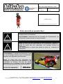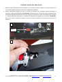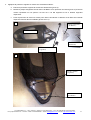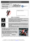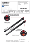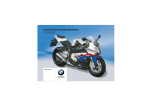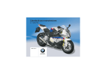
1
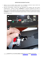
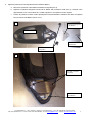
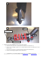
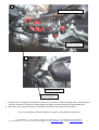
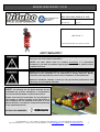
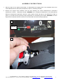
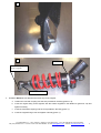
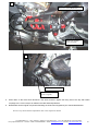
ISTRUZIONI DI MONTAGGIO XXF 11/31/B1
Codice/Code: D0038 XXF 11-31-B1
DUCATI 1199 PANIGALE 2012
Rev. 00
Mod. ISTR. MONT. XX
del 12/04/12
Pag. 1/6
N. DI MATRICOLA
DA INDICARE IN CASO DI RECLAMO
PRIMA LA TUA SICUREZZA !
L’ Ammortizzatore è un importante componente della Moto e in questo manuale
è descritto il metodo corretto per il montaggio di esso sulla moto.
NOTA BENE: l’Ammortizzatore deve essere installato unicamente presso
un’officina specializzata; in caso di dubbi sulle istruzioni qui contenute, Vi
preghiamo di contattare subito un tecnico Bitubo.
Bitubo non potrà essere responsabile di modifiche apportate Prodotto che non
sono contenute in questo manuale, e che non sono autorizzate per iscritto.
Bitubo inoltre non potrà essere responsabile di una non corretta installazione
del Prodotto.
Leggete attentamente questo manuale, per ottenere dall’Ammortizzatore il
massimo delle prestazioni e del rendimento.
NOTA BENE: la garanzia dell’Ammortizzatore cessa
nel caso in cui venga montato in maniera errata, o
modificato, senza l’approvazione scritta da Bitubo.
Bitubo non potrà essere responsabile di danni al
prodotto o alle persone, in caso le istruzioni contenute
in questo manuale non vengano seguite esattamente,
o in caso il montaggio dell’Ammortizzatore non venga
effettuato presso una officina specializzata, e da
personale qualificato.
BITUBO RACCOMANDA
Le immagini e le indicazioni riportate sono a titolo indicativo; C.d.a. Bitubo si riserva la facoltà apportare qualsiasi modifica o variazione senza alcun
preavviso.
C.D.A. BITUBO s.n.c. – Via A. Volta,24 – 35037 Z.I. Teolo (PD) ITALY – Tel. (+39) 049-990.34.75 (2 linee ISDN)
Fax (+39) 049-990.34.47 – Cod Fisc. e Part. IVA 02007650282 – E-mail: [email protected] - Internet: http://www.bitubo.com
1
ISTRUZIONI DI MONTAGGIO
1. Mettere la moto sul cavalletto centrale originale. Per lo smontaggio dei particolari originali, attenersi alle
indicazioni della Casa (Libretto Uso/Manutenzione – Manuale di Officina).
2. Rimuovere l’ammortizzatore originale dalla moto attendendosi alle indicazioni della Casa (Libretto
Uso/Manutenzione – Manuale di Officina). ATTENZIONE: la conseguente disabilitazione del sistema di
gestione elettronica delle sospensioni DES (Ducati Electronic Suspension) determina accensione spia sul
cruscotto (foto 1): tale anomalia può essere ignorata utilizzando sospensioni non gestite da tale sistema.
ATTENZIONE: una volta rimosso l’ammortizzatore originale rivestire con nastro isolante entrambi i connettori
del sistema DES (foto 2).
1
Anomalia
DES
2
C.D.A. BITUBO s.n.c. – Via A. Volta,24 – 35037 Z.I. Teolo (PD) ITALY – Tel. (+39) 049-990.34.75 (2 linee ISDN)
Fax (+39) 049-990.34.47 – Cod Fisc. e Part. IVA 02007650282 – E-mail: [email protected] - Internet: http://www.bitubo.com
2
3. Applicare protezione molla originale all’ammortizzatore Bitubo:
a. Rimuovere protezione molla dall’ammortizzatore originale (foto 3)
b. Applicare la piastrina triangolare fornita nel kit Bitubo alla protezione molla (foto 3), e fissarla come
rappresentato in foto 4-5 mediante le 2 viti M5 originali e le 2 rispettive boccole originali.
c.
Fissare la protezione molla al collare predisposto nell’ammortizzatore mediante vite M6 e la rispettiva
boccola fornite nel kit Bitubo (foto 2-4-6-7).
3
Piastrina triangolare
(kit Bitubo)
Protezione molla
Vite M6 + boccola
(kit Bitubo)
Vite M5 + boccola
(originali)
4
Vite M5 + boccola
(originali)
Vite M6 + boccola
(kit Bitubo)
C.D.A. BITUBO s.n.c. – Via A. Volta,24 – 35037 Z.I. Teolo (PD) ITALY – Tel. (+39) 049-990.34.75 (2 linee ISDN)
Fax (+39) 049-990.34.47 – Cod Fisc. e Part. IVA 02007650282 – E-mail: [email protected] - Internet: http://www.bitubo.com
3
5
6
Collare
Vite attacco
lato stelo (originale)
Rondella (kit Bitubo)
4. Installare l’ammortizzatore Bitubo allo stesso modo di quello originale:
a. Posizionare attacco lato stelo in corrispondenza del rispettivo foro a telaio (foto 7-8);
b. Inserire la vite di fissaggio originale con la rondella sostitutiva fornita nel kit Bitubo (foto 6-7-8), e
serrare a mano;
c.
Inserire attacco lato testina in corrispondenza della rispettiva forcella a telaio (foto 7);
d. Inserire la vite di fissaggio originale e serrare a mano (foto 7);
C.D.A. BITUBO s.n.c. – Via A. Volta,24 – 35037 Z.I. Teolo (PD) ITALY – Tel. (+39) 049-990.34.75 (2 linee ISDN)
Fax (+39) 049-990.34.47 – Cod Fisc. e Part. IVA 02007650282 – E-mail: [email protected] - Internet: http://www.bitubo.com
4
7
Vite M6 + boccola (kit Bitubo)
Vite attacco
lato testina (originale)
8
Rondella (kit Bitubo)
Vite attacco
lato stelo (originale)
5. Eseguire alcuni molleggi sulla sospensione posteriore, poi serrare i dadi di fissaggio delle viti degli attacchi
superiore ed inferiore, secondo la corretta coppia di serraggio indicata nel Manuale di Officina della moto.
6. Rimontare i tutti i componenti originali, seguendo le indicazioni fornite dalla Casa Costruttrice.
N.B. Per le regolazioni dell’ammortizzatore, consultare il manuale della sospensione.
C.D.A. BITUBO s.n.c. – Via A. Volta,24 – 35037 Z.I. Teolo (PD) ITALY – Tel. (+39) 049-990.34.75 (2 linee ISDN)
Fax (+39) 049-990.34.47 – Cod Fisc. e Part. IVA 02007650282 – E-mail: [email protected] - Internet: http://www.bitubo.com
5
MOUNTING INSTRUCTION XXF 11/31/B1
Codice/Code: D0038 XXF 11-31-B1
DUCATI 1199 PANIGALE 2012
Rev. 00
Mod. ISTR. MONT. XX
del 12/04/12
Pag. 3/6
SERIAL N.
(SEE PAGE 1)
TO BE MENTIONED IN CASE OF CLAIM
FIRST YOUR SAFETY !
The rear Shock is an important component of the motorcycle and this manual
describes the correct way to assemble it.
NOTE: The Rear Shock must be installed exclusively in a specialised
workshop; if you have any doubts regarding these instructions, please contact
a Bitubo technician.
Bitubo cannot be held responsible for any modifications to the Rear Shock not
described in this handbook or not authorised in writing. Moreover Bitubo
cannot be held responsible for the incorrect installation of shock absorber.
Read this handbook carefully so that you can get the best performance and
efficiency out of the Shock absorber.
NOTE: The warranty for the Shock absorber will be
invalidated by incorrect installation or modifications
carried out without Bitubo’s written authorisation.
Bitubo cannot be held responsible for any damages to
the product or injuries to people if the instructions of
this handbook are not followed to the letter or if the
Shock absorber is not fitted in a specialised workshop
or by qualified personnel.
BITUBO RECOMMENDS
Pictures and notes reported are purely as an indications; C.d.a. Bitubo reserves the faculty to make any modification or changes.
C.D.A. BITUBO s.n.c. – Via A. Volta,24 – 35037 Z.I. Teolo (PD) ITALY – Tel. (+39) 049-990.34.75 (2 linee ISDN)
Fax (+39) 049-990.34.47 – Cod Fisc. e Part. IVA 02007650282 – E-mail: [email protected] - Internet: http://www.bitubo.com
6
ASSEMBLY INSTRUCTIONS
1. Place the bike on the original central stand. To disassemble the original parts of the motorbike refer to the
vehicle Manufacturer’s instructions (Use/Service manual – Workshop manual)..
2. Remove the original shock absorber from the bike following the vehicle Manufacturer’s instructions
(Use/Service manual – Workshop manual). WARNING: the consequent disablement of the DES (Ducati
Electronic Suspension) suspension electronic control system causes the light on the dashboard to light up
(photo 1): this fault can be ignored by using suspensions not controlled by this system. WARNING: once the
original shock absorber has been removed, cover both DES connectors with tape (photo2).
1
DES fault
2
C.D.A. BITUBO s.n.c. – Via A. Volta,24 – 35037 Z.I. Teolo (PD) ITALY – Tel. (+39) 049-990.34.75 (2 linee ISDN)
Fax (+39) 049-990.34.47 – Cod Fisc. e Part. IVA 02007650282 – E-mail: [email protected] - Internet: http://www.bitubo.com
7
3. Apply the original spring guard to the Bitubo shock absorber:
a. Remove the spring guard from the original shock absorber (photo 3)
b. Apply the triangular plate supplied in the Bitubo kit onto the spring guard (photo 3) and fix it as shown
in photos 4-5 using the 2 M5 original screws and the 2 respective original bushes.
c.
Fix the spring guard to the shock absorber collar using the M6 screw and respective bush supplied in
the Bitubo kit (photos 2-4-6-7).
3
Triangular plate
(Bitubo kit)
Spring guard
M6 screw + bush
(Bitubo kit)
M5 screw + bush
(original)
4
M5 screw + bush
(original)
M6 screw + bush
(Bitubo kit)
C.D.A. BITUBO s.n.c. – Via A. Volta,24 – 35037 Z.I. Teolo (PD) ITALY – Tel. (+39) 049-990.34.75 (2 linee ISDN)
Fax (+39) 049-990.34.47 – Cod Fisc. e Part. IVA 02007650282 – E-mail: [email protected] - Internet: http://www.bitubo.com
8
5
6
Collar
Rod-side coupling
screw (original)
Washer (Bitubo kit)
4. Install the Bitubo shock absorber the same way as the original:
a. Position the rod-side coupling onto the hole provided in the body (photos 7-8);
b. Insert the original fixing screw together with the washer supplied in the Bitubo kit (photos 6-7-8) and
tighten manually;
c.
Insert the head-side coupling onto the fork provided in the body (photo 7);
d. Insert the original fixing screw and tighten manually (photo 7);
C.D.A. BITUBO s.n.c. – Via A. Volta,24 – 35037 Z.I. Teolo (PD) ITALY – Tel. (+39) 049-990.34.75 (2 linee ISDN)
Fax (+39) 049-990.34.47 – Cod Fisc. e Part. IVA 02007650282 – E-mail: [email protected] - Internet: http://www.bitubo.com
9
7
M6 screw + bush (Bitubo kit)
Head-side coupling
screw (original)
8
Washer (Bitubo kit)
Rod-side coupling
screw (original)
5. Press down on the back shock absorber a few times and then tighten the fixing nuts of the top and bottom
couplings to the correct torque as stated in the bike Workshop Manual.
6. Reassemble all the original components following the instructions supplied by the vehicle Manufacturer.
N.B. For any shock absorber adjustments refer to the suspension manual.
C.D.A. BITUBO s.n.c. – Via A. Volta,24 – 35037 Z.I. Teolo (PD) ITALY – Tel. (+39) 049-990.34.75 (2 linee ISDN)
Fax (+39) 049-990.34.47 – Cod Fisc. e Part. IVA 02007650282 – E-mail: [email protected] - Internet: http://www.bitubo.com
10
Codice/Code: D0038 XXF 11-31-B1
DUCATI 1199 PANIGALE 2012
Rev. 00
Mod. ISTR. MONT. XX
del 12/04/12
Pag. 5/6
N. DE SERIE
(VOIR PAGE 1)
A INDIQUER EN CAS DE RECLAMATION
Votre sécurité en premier lieu !
L’amortisseur est un composant fondamental de la moto. Ce manuel décrit le
montage correct de l’amortisseur.
AVERTISSEMENT: l’amortisseur doit être assemblé par un professionnel. En
cas de doute, veuillez consulter un technicien Bitubo.
Bitubo ne pourra être tenu responsable de toute modification apportée au
produit qui n’est pas décrite dans ce manuel, ou n’a pas été autorisée par écrit.
Bitubo ne pourra être tenu responsable d’un montage incorrect de
l’amortisseur.
Lisez attentivement ce manuel pour profiter au mieux du rendement de
l’amortisseur.
AVERTISSEMENT: la garantie de l’amortisseur cesse
en cas de montage incorrect et/ou de modifications
apportées sans approbation écrite de Bitubo.
Bitubo ne pourra être tenu responsable des
dommages au produit et/ou aux personnes si les
instructions de montage n’ont pas été suivies
exactement, ou si le montage n’a pas été effectué
dans un garage spécialisé par un personnel qualifié.
BITUBO RECOMMANDER
Les images et les indications sont indicatives; C.d.a. Bitubo se réserve le droit de modifier ce manuel sans préavis.
C.D.A. BITUBO s.n.c. – Via A. Volta,24 – 35037 Z.I. Teolo (PD) ITALY – Tel. (+39) 049-990.34.75 (2 linee ISDN)
Fax (+39) 049-990.34.47 – Cod Fisc. e Part. IVA 02007650282 – E-mail: [email protected] - Internet: http://www.bitubo.com
11
INSTRUCTIONS DE MONTAGE
1. Mettez la moto sur la béquille centrale originale. Pour démonter les pièces originales, suivez les indications du
constructeur (Manuel d’utilisation et d’entretien – Manuel de réparation).
2. Enlevez l’amortisseur original de la moto en suivant les indications du constructeur (Manuel d’utilisation et
d’entretien – Manuel de réparation). ATTENTION : la désactivation du système de gestion électronique des
suspensions DES (Ducati Electronic Suspension) provoque l’allumage du voyant sur le tableau de bord (photo
1) : cette anomalie peut être ignorée en utilisant des suspensions non gérées par ce système. ATTENTION :
après avoir enlevé l’amortisseur original, recouvrez les deux connecteurs du système DES (photo 2) de
chatterton.
1
Anomalie
DES
2
C.D.A. BITUBO s.n.c. – Via A. Volta,24 – 35037 Z.I. Teolo (PD) ITALY – Tel. (+39) 049-990.34.75 (2 linee ISDN)
Fax (+39) 049-990.34.47 – Cod Fisc. e Part. IVA 02007650282 – E-mail: [email protected] - Internet: http://www.bitubo.com
12
3. Appliquez la protection originale du ressort sur l’amortisseur Bitubo :
a. Enlevez la protection originale du ressort de l’amortisseur (photo 3).
b. Montez la plaque triangulaire fournie dans le kit Bitubo sur la protection du ressort (photo 3) et fixez-la
comme représenté sur les photos 4-5 avec les 2 vis M5 originales et les 2 douilles originales
respectives.
c.
Fixez la protection du ressort au collier prévu dans l’amortisseur à l’aide de la vis M6 et de la douille
respective fournies dans le kit Bitubo (photos 2-4-6-7).
3
Plaque triangulaire
(kit Bitubo)
Protection ressort
Vis M6 + douille
(kit Bitubo)
Vis M5 + douille
(originales)
4
Vis M5 + douille
(originales)
Vis M6 + douille
(kit Bitubo)
C.D.A. BITUBO s.n.c. – Via A. Volta,24 – 35037 Z.I. Teolo (PD) ITALY – Tel. (+39) 049-990.34.75 (2 linee ISDN)
Fax (+39) 049-990.34.47 – Cod Fisc. e Part. IVA 02007650282 – E-mail: [email protected] - Internet: http://www.bitubo.com
13
5
6
Collier
Vis embout
côté tige (originale)
Rondelle (kit Bitubo)
4. Montez l’amortisseur Bitubo de la même façon que celui original :
a. Positionnez l’embout côté tige à la hauteur du trou correspondant sur le cadre (photos 7-8) ;
b. Introduisez la vis de fixation originale et la rondelle de remplacement fournie dans le kit Bitubo (photos
6-7-8) et serrez à la main ;
c.
Placez l’embout côté tête à la hauteur de la fourche respective sur le cadre (photo 7) ;
d. Introduisez la vis de fixation originale et serrez à la main (photo 7) ;
C.D.A. BITUBO s.n.c. – Via A. Volta,24 – 35037 Z.I. Teolo (PD) ITALY – Tel. (+39) 049-990.34.75 (2 linee ISDN)
Fax (+39) 049-990.34.47 – Cod Fisc. e Part. IVA 02007650282 – E-mail: [email protected] - Internet: http://www.bitubo.com
14
7
Vis M6 + douille (kit Bitubo)
Vis embout
côté tête (originale)
8
Rondelle (kit Bitubo)
Vis embout
côté tige (originale)
5. Faîtes quelques manœuvres sur la suspension arrière et serrez les écrous de fixation des vis des embouts
supérieur et inférieur au couple de serrage indiqué dans le Manuel de réparation de la moto.
6. Remontez tous les composants originaux, en suivant les indications fournies par le constructeur.
N.B. Pour régler l’amortisseur, consultez le manuel de la suspension.
C.D.A. BITUBO s.n.c. – Via A. Volta,24 – 35037 Z.I. Teolo (PD) ITALY – Tel. (+39) 049-990.34.75 (2 linee ISDN)
Fax (+39) 049-990.34.47 – Cod Fisc. e Part. IVA 02007650282 – E-mail: [email protected] - Internet: http://www.bitubo.com
15