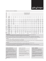
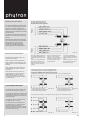
1
Schrittmotor ZSS 19-56
Stepper motor ZSS 19-56
Moteur pas à pas ZSS 19-56
¸
ZSS/98-1
Präzisions-Schrittmotoren ZSS
ZSS precision stepper motors
Moteurs pas à pas de précision ZSS
”
Zweiphasen-Hybrid-Schrittmotoren
für unipolare und bipolare Ansteuerung
”
Two-phase hybrid stepper motors
for unipolar and bipolar control
” Moteurs pas à pas biphasés hybrides
Haltemomente 3,8 bis 700 mNm
”
Holding torques 3.8 to 700 mNm
”
Sizes ZSS 19 through 56
”
Baugrößen ZSS 19 bis 56
”
”
Bis zu 3 verschiedene Motortypen
und 3 Standardwicklungen pro Baugröße
”
Up to 3 motor types and 3 different
standard windings per size
”
Standard number of steps: 200
Special numbers of steps depending
on the motor size: 8, 24, 56, 72 and
500
”
Standardschrittzahl 200
Sonderschrittzahlen je nach Baugröße: 8, 24, 56, 72, 500
”
Schutzart mindestens IP 40
Baugröße ZSS 56 enthält in der
Standardbaureihe zusätzlich unter
der Typenbezeichnung ZSS 59
einen Schrittmotor in IP 65-Ausführung.
”
Isolierstoffklasse F
”
Zulässige Oberflächentemperatur
–20 gC bis +120 gC
”
Phytron Präzisions-Schrittmotoren
ZSS werden in den unterschiedlichsten Bereichen eingesetzt, z.B. in
der Fertigung, im Apparatebau oder
in optischen Geräten.
”
Informationsmaterial zum EMVgerechten Anschluß von Schrittmotoren auf Anfrage. Beachten Sie
die Unterlagen der eingesetzten
Steuerung bzw. Endstufe.
pour commande unipolaire ou bipolaire
” Couples de maintien : 3,8 à 700 mmN
” Taille ZSS 19 à 56
” Jusqu’à 3 types de moteur et 3 enrou-
lements standards par taille
” Nombre de pas en version standard : 200
Nombres de pas spéciaux selon la
taille du moteur : 8, 24, 56, 72 et 500
”
Minimum protection mode IP 40
Size ZSS 56 includes, for the standard types, a stepper motor with IP
65 protection: ZSS 59.
” Mode de protection minimal IP 40
”
Insulation class: F
” Classe d’isolation : F
”
Permissible surface temperature:
–20 gC to +120 gC
” Température de surface admissible :
”
Phytron ZSS precision stepper
motors are used for various applications, e.g. for automated production
equipment, for measuring and
optical instruments.
” Les moteurs pas à pas de précision
”
Information on stepper motor
connection in conformity with EMC
requirements on request.
Please, refer to the instruction
manuals of the corresponding power
stages and control units.
En série standard, la taille ZSS 56
intègre un moteur pas à pas avec
mode de protection IP 65 : ZSS 59.
–20 gC à +120 gC
Phytron de la série ZSS sont utilisés
pour de nombreuses applications, par
exemple, les équipements de production automatisée, les appareils de
mesure et d’optique.
” Informations pour le raccordement
des moteurs pas à pas conforme à la
compatibilité électromagnétique
(CEM) sur demande.
Reportez-vous aux manuels d’utilisation de l’étage de puissance et de
l’unité de commande correspondants.
Bestellschlüssel / Ordering data / Références de commande
ZSS 42 . 200 . 1,2 - E - K1 - HD 11 / 50 - FD
Schrittmotorbauform
Stepper motor series
Moteur pas à pas, série
Typ / Type / Type 1)
Schrittzahl / Number of steps/rev. / Nombre de pas/tour
8 / 24 / 56 / 72 / 200 / 500
Wicklung / Winding / Enroulement
0,3 / 0,6 / 1,2 / 2,5 / 5 A
Optionen / Options
– 2. Wellenende E / 2nd shaft end E / 2e arbre de sortie E (IP 40)
– Inkrementalgeber / Incremental encoder / Codeur incrémental HEDL 5540 (IP20)
ZSS 59: auf Anfrage / on request / sur demande (IP 65)
– Bremse / Brake / Frein moteur KEB 02 (IP 00)
Kühlkörper / Heat sink / Radiateur
K1 radial / radial / radiale – K2 axial / axial / axiale
Getriebe/Untersetzung
Gearing/Reduction ratio
Réducteur/rapport de réduction
PLG / GPL / HD
Option freie Drahtenden FD (IP 40) für Baugröße 42-56 ohne Bremse
FD free wire end option (IP 40) for size 42 to 56 without brake
Option fils libres FD (IP 40) pour tailles 42 à 56 sans frein
1)
ZSS 19 bis 43: Bemessungsspannung nach EN 60034/1: [ 100 V (Motor ohne Erdungsschraube)
ZSS 41/1 bis ZSS 43/1, ZSS 52 bis ZSS 59: [ 200 V (Motor mit Erdungsschraube)
ZSS 19 to 43: Design voltage acc. to EN 60034/1: [ 100 V (motor without earthing screw)
ZSS 41/1 to ZSS 43/1, ZSS 52 to ZSS 59: [ 200 V (motor with earthing screw)
ZSS 19 à 43 : Tension de dimensionnement selon EN 60034/1 : [ 100 V (moteur sans vis de terre)
ZSS 41/1 à ZSS 43/1, ZSS 52 à ZSS 59 : [ 200 V (moteur avec vis de terre)
2
ZSS
Optionen
Options
Options
”
Zweites Wellenende
”
Second shaft end
” Deuxième arbre de sortie
”
Kühlkörper mit radialen (K1) oder
axialen Rippen (K2)
”
Heat sink with radial (K1) or axial
fins (K2)
” Radiateur avec ailettes radiales (K1)
”
Planetengetriebe PLG für Baugrößen
ZSS 25 - 56
”
PLG planetary gearing for motor
sizes ZSS 25 through 56
” Réducteur planétaire PLG pour
”
Spielarme Planetengetriebe GPL für
Baugrößen ZSS 19 - 56
”
GPL low backlash planetary gearing
for motor sizes ZSS 19 through 56
” Réducteur planétaire à faible jeu GPL
”
Harmonic Drive Getriebe HD für
Baugrößen ZSS 25 - 52
”
Inkrementalgeber HEDL 5540 für
Baugrößen ZSS 25 - 56
”
”
Motorbremse KEB 02 für Baugrößen
ZSS 52 und 56
”
KEB 02 brake for motor sizes ZSS
52 and 56
”
Sonderbauformen für Extremanwendungen:
” Vakuum bis 10–11 hPa
” Reinraum
” Erweiterte Temperaturbereiche
von –270 gC bis +300 gC
” Strahlenresistent bis 106 J/kg
”
Special versions for applications
under extreme environmental
conditions:
” Vacuums up to 10–11 hPa
” Clean rooms
” Extended temperature ranges:
–270 gC to +300 gC
” Radiation-resistant up to 106 J/kg
”
Die Schrittmotoren ZSS 19 - 56
werden für den jeweiligen Extrembereich – auch Kombinationen sind
möglich – speziell aufgebaut. Die
Abmessungen der Sonderbauformen können geringfügig von den
Standardmaßen abweichen.
”
HD Harmonic Drive gearing for
motor sizes ZSS 25 through 52
HEDL 5540 incremental encoder for
motor sizes ZSS 25 through 56
Depending on the environmental
conditions, even combined, ZSS 19 56 stepper motors include specific
materials and components. Therefore, the dimensions of special
versions may differ slightly from
those of the standard types.
Informationsmaterial auf Anfrage
”
Further information on request
ou axiales (K2)
moteurs de taille ZSS 25 à 56
pour moteurs ZSS 19 à 56
” Réducteur ”Harmonic Drive” HD
pour moteurs ZSS 25 à 52
” Codeur incrémental HEDL 5540
pour moteurs ZSS 25 à 56
” Frein KEB 02 pour moteurs de taille
ZSS 52 et 56
” Versions spéciales pour applications
dans des conditions d’environnement
extrêmes :
” pour le vide jusqu’à 10–11 hPa
” pour salles blanches
” pour températures extrêmes :
–270 gC à +300 gC
” résistants aux radiations jusqu’à
106 J/kg
En fonction des conditions d’environnement éventuellement combinées, les
moteurs pas à pas ZSS 19 - 56 comportent des composants et matériaux
spécifiques. Les dimensions des
versions spéciales peuvent ainsidifférer de celles des versions standards.
” Documentation sur demande
Option: Motorbremse KEB 02
Option: KEB 02 motor brake
Option : F rein moteur KEB 02
Für vertikale Positioniereinheiten
stehen Schrittmotoren mit angebauter
Motorbremse zur Verfügung.
For vertical positioning units, stepper
motors with built-in brake are available.
Pour les systèmes de positionnement
verticaux il existe des moteurs pas à pas
avec frein.
Die Bremswirkung der Permanentmagnet-Motorbremse tritt ein, wenn
die Versorgungsspannung der Bremse
ausgeschaltet wird. Der Permanentmagnet zieht eine eingebaute Ankerscheibe in axialer Richtung an die
Gegenreibfläche. Es entsteht eine reibschlüssige, drehspielfreie Verbindung.
Ist der Strom eingeschaltet, wird die
Kraftwirkung auf den Anker aufgehoben. Die Reibflächen werden unabhängig von der Einbaulage durch eine
angenietete Feder restmomentfrei
getrennt.
]
Versorgungsspannung: 24 VDC
]
Elektrischer Anschluß der Motorbremse über Steckverbinder
The brake effect of the permanent
magnet brakes becomes effective
when the supply current of the brake is
interrupted. The permanent magnet
pulls a built-in armature disk in the
axial direction against the friction disk,
creating a tight, torsion-free connection.
When the current is switched on, the
force acting on the armature is
suppressed. The friction surfaces are
separated without any residual torque,
by means of a riveted spring, whatever
the mounting position.
]
Supply voltage: 24 VDC
]
Electrical connection of the brake by
means of a connector
]
Current consumption: approx.
350 mA
]
Strombedarf: ca. 350 mA
]
Leistung: 8 W
]
Power: 8 W
]
Nennmoment: 0,75 Nm
]
Nominal torque: 0.75 Nm
]
Abmessungen auf Anfrage
]
Dimensions on request
ZSS
Le freinage est obtenu lorsque l’alimentation du frein est interrompue. L’aimant
permanent attire alors le disque d’induit
intégré dans le sens axial et le plaque
contre un disque de friction. Une liaison
ferme, sans jeu rotationnel, est ainsi
créée.
Lorsque le courant est rétabli, la force
d’attraction est annulée. Les surfaces de
friction sont séparées à l’aide d’un
ressort riveté, sans couple résiduel, quelque soit la position de montage.
] Tension d’alimentation : 24 VDC
] Raccordement électrique du frein par
connecteur
] Consommation en courant :
env. 350 mA
] Puissance : 8 W
] Couple normal : 0,75 Nm
] Dimensions sur demande
3
Option:
Inkrementalgeber HEDL 5540
Option: HEDL 5540
incremental encoder
Option : Codeur incrémental
HEDL 5540
ZSS-Schrittmotoren mit angebautem
Inkrementalgeber sind für Einsatzgebiete sinnvoll, in denen eine schrittgenaue Überwachung der Positioniervorgänge erforderlich ist.
ZSS stepper motors with built-in
incremental encoders are used in all
applications where each step must be
monitored during positioning.
Les moteurs pas à pas ZSS avec codeur
incrémental intégré sont utilisés pour les
applications nécessitant une surveillance
de chaque pas pendant le positionnement.
]
Optischer Inkrementalgeber
]
Standardauflösung 500 Strich
]
Ausgangssignale:
]
Kanal A und B
Die Signale A und B sind um 90g
phasenverschoben.
]
Referenzimpuls 0
/
]
Versorgungsspannung 5 VDC
]
Elektrischer Anschluß des Inkrementalgebers: Flachbandkabel mit
10pol. Steckverbinder
]
Mit kurzschlußfestem DifferentialLeitungstreiber
]
Output signals:
] Channel A and B
The A and B signals are shifted
by 90g
] 0
/ -reference pulse
] Codeur incrémental optique
] Résolution standard :
500 traits
] Signaux de sortie :
] Voies A et B
Les signaux A et B sont décalés
de 90g.
] Impulsion de référence 0
/
]
Supply voltage: 5 VDC
]
Electrical connection of the
incremental encoder: flat cable with
10-point connector
] Alimentation : 5 VDC
Dimensions on request
] Raccordement électrique du codeur
]
La complémentation de ces signaux
est également disponible.
incrémental : câble plat avec connecteur 10-pôles
Incremental encoder for ZSS 59:
] Dimensions sur demande
]
With short-circuit proof differential
line driver
Codeur incrémental pour ZSS 59 :
]
Soldered connection with cable
gland
Elektrischer Anschluß: Lötanschluß
und Kabelverschraubung
Anmerkungen zur Typenübersicht:
4
Standard resolution: 500 lines
Abmessungen auf Anfrage
Inkrementalgeber für ZSS 59:
]
Optical incremental encoder
]
These outputs are also available as
inverted signals.
Alle Ausgangssignale sind auch
invertiert verfügbar.
]
]
”
2)
Durchmesser Kabelauslaß:
max. 4,5 mm bei Baugröße 42
max. 5 mm bei Baugröße 52-56
3)
AWG 28, freie Drahtenden 250 mm
4)
AWG 26, freie Drahtenden 250 mm
5)
siehe separate Datenblätter
6)
Option Inkrementalgeber:
ZSS 32-57: Motoranschluß über
freie Drahtenden, Inkrementalgeberanschluß Flachbandkabel mit 10pol.
ICD-Steckverbinder (IP 20)
ZSS 59: Motor- und Inkrementalgeberanschluß über Anschlußkasten
mit Lötanschluß und Kabelverschraubung (IP 65)
7)
Option Bremse (IP 00):
Motoranschluß: Anschlußkasten mit
Lötanschluß und Kabelverschraubung
Anschluß der Motorbremse: Rundsteckverbinder
8)
[100
[200
9)
ZSS 52-57 mit 5 A-Wicklung:
Motoranschluß mit Anschlußkasten,
Lötanschluß und Kabelverschraubung (IP 50)
10)
HEDL 5540
– Vorzugstypen
]
– Option
V: Motor ohne Erdungsschraube
V: Motor mit Erdungsschraube
tiel, protégé contre les courts-circuits
] Raccordement soudé avec passage par
presse-étoupe
Remarks to the list oftypes:
1)
1)
] Avec amplificateur de ligne différen-
”
– Popular types ] – Option
2)
Cable outlet diameter:
max. 4.5 mm for size 42
max. 5 mm for sizes 52-56
3)
AWG 28, free wires 250 mm
4)
AWG 26, free wires 250 mm
5)
Refer to separate data sheets
6)
Incremental encoder option
ZSS 32-57: Motor connection via
free wire ends, incremental encoder
via flat cable with 10-point ICD-connector (IP 20)
ZSS 59: Motor and incremental
encoder connection via terminal box
(soldered connection) and cable
gland (IP 65)
7)
Brake option (IP 00)
Motor connection via terminal box
(soldered connection) and cable
gland
Brake connection via a round connector
8)
[ 100 V: Motor without earthing screw
[ 200 V: Motor with earthing screw
9)
ZSS 52-57 with 5 A-winding: Motor
connection via terminal box
(soldered connection) and cable
gland (IP 50)
10)
HEDL 5540
11)
All dimensions are written with
comma (German style) instead of a
point.
Remarques à la liste des types :
1)
” – Type préférentiel
2)
Diamètre du câble de sortie :
max. 4.5 mm pour taille 42
max. 5 mm pour tailles 52-56
3)
AWG 28, fils libres de 250 mm
4)
AWG 26, fils libres de 250 mm
5)
Voir fiches techniques séparées
6)
Option codeur incrémental
ZSS 32-57 : raccordement du moteur
par fils libres, raccordement du
codeur incrémental par câble plat et
connecteur ICD 10-pôles (IP 20)
ZSS 59 : raccordement du moteur et
du codeur incrémental dans un boîtier
de raccordement (soudure) avec
presse-étoupe (IP 65)
7)
Option frein moteur (IP 00)
Raccordement du moteur dans un
boîtier de raccordement (soudure)
avec presse-étoupe
Raccordement du frein par connecteur rond
8)
[ 100 V : Moteur sans vis de terre
[ 200 V : Moteur avec vis de terre
9)
ZSS 52-57 avec enroulement 5 A :
raccordement du moteur dans un
boîtier de raccordement (soudure)
avec presse-étoupe (IP 50)
10)
HEDL 5540
] – Option
ZSS
52
56
ZSS
8 24 56 72 200 500
ZSS 19
ZSS 25
ZSS 20
25
ZSS 32
32
ZSS 33
42
ZSS 42
ZSS 42/1
ZSS 52
ZSS 56
]
”
] ]
”
ZSS 26
ZSS 41/1
ZSS41
ZSS 43/1
ZSS 43
”
”
”
”
”
”
”
”
”
]
ZSS 57
”
]
ZSS 59
”
]
] ”
”
”
”
”
]
”
0,3 0,6 1,2
”
]
”
]
0,3 0,6 1,2
0,6 1,2 2,5
0,6 1,2 2,5
1,2
2,5
1,2 2,5
2,5
5
5
”
”
”
”
”
”
”
”
”
”
”
”
1)
Wicklungen
Windings
Enroulements
]
]
]
]
]
7)
]
10)
]
10)
]
”
”
]
”
”
10)
]
10)
]
]
]
] ]
] ]
] ]
] ]
] ]
] ] ]
] ]
] ]
5)
] ]
] ]
]
]
]
]
]
]
]
]
]
]
]
]
]
]
]
Harmonic Drive Getriebe HD / HD Harmonic Drive gearing / Réducteur Harmonic Drive HD
]
]
]
] ]
” 9)
”
” 4)
F
2)
” 3)
” 3)
”
] ]
” 9)
3,8
mNm mNm
mNm mNm
0,9
kg cm2
N
Gewicht (Motor) / Weight (motor) / Poids (moteur)
Elektr. Anschluß
Wiring
Raccordement
radial / radial / radiale
1)
axial / axial / axiale
Massenträgheitsmoment / Mass inertia / Inertie de masse
Selbsthaltemoment / Detent torque / Couple d’auto-maintien
Haltemoment im bipolaren Betrieb (Schrittzahl 200) / Holding torque in the bipolar mode (Number of steps: 200)
Couple de maintien en mode bipolaire (Nombre de pas : 200)
Prüfspannung / Test voltage / Tension d’essai
Isolierstoffklasse nach EN 60034/1 / Insulating material class acc. to EN 60034/1 / Classe de l’isolant selon EN 60034/1
Anschlußkasten (Schutzart IP 65) / Terminal box (IP 65 protection) / Boî tier avec press-étoupe (Protection IP 65)
Anschlußkappe (Schutzart IP 50) / Terminal block with protective cover (IP 50 protection) / Boî tier avec passe-câble (Protection IP 50)
Freie Drahtenden (Schutzart IP 40) / Free wire ends (IP 40 protection) / Fils libres (Protection IP 40)
5)
Spielarme Planetengetriebe GPL / GPL Low backlash planetary gearing / Réducteur planétaire à faible jeu GPL
K1 K2
5)
Planetengetriebe PLG / PLG Planetary gearing / Réducteur planétaire PLG
Kühlkörper / Heat sink / Radiateur
6)
Bremse KEB 02 / KEB 02 Brake / Frein moteur KEB 02
8)
Inkrementalgeber / Incremental encoder / Codeur incrémental
2. Wellenende (IP 40) / 2nd shaft end / 2g arbre de sortie
[ 200 V
Bemessungsspannung nach EN 60034/1
Design voltage acc. to EN 60034/1
Tension de dimensionnement selon EN 60034/1
Optionen
Options
Options
700 V / 1 min
19
Schrittzahlen
Number of steps
Nombre de pas
[ 100 V
Typ
Type
Type
Phasenströme in A (bipolarer Betrieb)
Phase currents in A (bipolar operation)
Courants par phase en A (mode bipolaire)
1)
1500 V / 1 min
Baugröße / Size / Taille
Typenübersicht/Mechanische Kenndaten
List oftypes/Mechanical characteristics
Liste de types/Caractéristiques mécaniques
Zul. Lagerbelastung
Permissible
bearing load
Charge
admissible
des paliers
mmN mmN
kg
0,0009
3
3
0,04
10)
5
1
0,0016
3
3
0,065
13
2
0,0025
5
5
0,07
25
2,2
0,006
5
5
0,11
50
3
0,01
5
15
0,15
75
3,3
0,018
5
15
0,35
100
4
0,025
20
40
0,26
140
5
0,045
20
40
0,32
260
7
0,077
20
40
0,47
450
13
0,15
25
70
0,65
400
30
0,17
40
80
0,7
700
50
0,24
40
80
0,9
700
50
0,24
40
80
1,05
f Anmerkungen / Remarks / Remarques
5
Schrittmotor ZSS 19-32 mit freien Drahtenden
ZSS 19-32 stepper motor with free wire ends
Moteur ZSS 19-32 avec des fils libres
Motorflansch ZSS
ZSS Motor flange
Flasque moteur ZSS
Abb./Fig. 1
Schrittmotor ZSS 42-56 mit Anschlußkappe
ZSS 42-56 stepper motor with terminal block and protective cover
Kühlkörper K1 für Schrittmotortypen ZSS 19-57
K1 heat sink for stepper motors ZSS 19-57
Moteur pas à pas ZSS 42-56 avec couvercle de protection
Radiateur K1 pour moteurs pas à pas ZSS 19-57
Abb./Fig. 2
Abb./Fig. 5
Schrittmotor ZSS 59 (IP 65) mit Kabelverschraubung
ZSS 59 stepper motor (IP 65) with cable gland
Kühlkörper K2 für Schrittmotortypen ZSS 19-57
K2 heat sink for stepper motors ZSS 19-57
Moteur pas à pas ZSS 59 (IP 65) avec presse-étoupe
Radiateur K2 pour moteurs pas à pas ZSS 19-57
Abb./Fig. 3
6
Abb./Fig. 4
Abb./Fig. 6
ZSS
Baugröße/ Size/ Taille
Maßtabelle / Dimensions / Dimensions
19
25
32
42
52
561)
Abmessungen in mm
Dimensions in mm
Dimensions en mm
Typ
Type
A
B1
ZSS 19
19
ZSS 20
19
ZSS 25
ZSS 26
B2
C
D
E
F1
F2
G1g5
G2g5
K
Lg6
M
N
P
R
26,5
1
2
7,5
6,5
2,5
2,5
19
10
16
M 2,5
26
20,5
43
1
2
7,5
6,5
2,5
2,5
19
10
16
M 2,5
26
37
25
31
1
2,5
9,5
8,5
3
3
25
14
21,5
2,2
35
24
25
47
1
2,5
9,5
8,5
3
3
25
14
21,5
2,2
35
40
ZSS 32
32
38,5
1
3
11
10
4
4
32
18
27
2,8
42
30
ZSS 33
32
57,5
1
3
11
10
4
4
32
18
27
2,8
42
49
ZSS 41
ZSS41/1
42
49
39
1
3
16
15
5
4
42
22
36
3,2
55
30
ZSS 42
ZSS 42/1
42
64
54
1
3
16
15
5
4
42
22
36
3,2
55
45
ZSS 43
ZSS 43/1
42
79
69
1
3
16
15
5
4
42
22
36
3,2
55
60
ZSS 522)
Type
52
77
65
1,5
3,5
17,5
16
6
4
52
28
44
4,3
65
58
2)
ZSS 56
56,4
69,1
57,1
1,5
4,5
22
20,5
6,35
6,35
60
38,1
47,15
5,2
78
44
ZSS 572)
56,4
85,1
73,1
1,5
4,5
22
20,5
6,35
6,35
60
38,1
47,15
5,2
78
60
ZSS 59
59
93
1,5
4,5
21
60
38,1
49,2
5,2
6,35
Anmerkungen:
1) Die Baugröße 56 enthält neben den Standardtypen ZSS 56 und 57 den Motortyp ZSS 59 in Schutzart IP 65.
ZSS 59 ist standardmäßig mit Anschlußkasten und Kabelverschraubung aufgebaut.
2) ZSS 52, 56 und 57, Wicklung 5 A: Statt mit Anschlußkappe wie in der Zeichnung (Abb. 2) dargestellt, sind diese Motoren
mit Anschlußkasten und Kabelverschraubung aufgebaut. Das Maß B2 (ZSS 52/56/57) vergrößert sich dadurch um 11 mm.
Remarks:
1) Size 56 includes, in addition to the ZSS 56 and 57 standard types, the ZSS 59 special motor with IP 65 protection.
ZSS 59 is normally delivered with terminal box and cable gland.
2) ZSS 52, 56 and 57, 5 A-winding: Instead of the terminal block with cover as shown (fig. 2), these motors are supplied with terminal box
and cable gland. Therefore, dimension B2 (ZSS 52/56/57) is increased by 11 mm.
Remarques :
1) La taille 56 inclut, en plus des types standards ZSS 56 et 57, le moteur spécial ZSS 59 en protection IP 65.
Le moteur ZSS 59 est normalement livré avec boîtier de raccordement et presse-étoupe.
2) ZSS 52, 56 et 57, enroulement 5 A : à la place du passe-câble (fig. 2), le boî tier de raccordement est livré avec presse-étoupe.
La cote B2 (ZSS 52/56/57) est donc augmentée de 11 mm.
Option: Kühlkörper
Option: Heat sink
Option : Radiateur
Die Schrittmotortypen ZSS 19 bis 57 gibt es
auch mit angebautem Kühlkörper.
ZSS 19 through ZSS 57 are also available
with a mounted heat sink.
Les moteurs ZSS 19 à ZSS 57 peuvent être
également livrés avec un radiateur monté.
Je nach Einbaulage des Schrittmotors kann
ein Kühlkörper mit radialen Rippen (K1)
oder mit axialen Rippen (K2) ausgewählt
werden.
Bei Verwendung eines Kühlkörpers K1 vergrößert sich die wärmeabgebende Oberfläche des Schrittmotors etwa um den Faktor
3,9. Wird ein Kühlkörper K2 eingesetzt, ist
die Oberfläche etwa um den Faktor 3,4 größer.
Der nachträgliche Anbau eines Kühlkörpers
ist möglich, sollte aber von Phytron durchgeführt werden.
Depending on the motor’s mounting position, a heat sink with radial fins (K1) or with
axial fins (K2) can be selected.
Selon la position de montage du moteur, un
radiateur choisiaura des ailettes radiales (K1)
ou axiales (K2).
The use of a K1 heat sink increases the
stepper motor’s thermal dissipation surface
by a factor of approx. 3.9. With a K2 heat
sink, it is increased by a factor of approx. 3.4.
L’utilisation d’un radiateur type K1 augmente
la dissipation thermique du moteur en surface
d’un facteur d’environ 3.9. Un radiateur de
type K2 l’augmente d’un facteur d’environ 3.4.
A heat sink can be mounted subsequently,
preferably by Phytron.
Le montage ultérieur d’un radiateur est possible mais devrait être effectué de préférence
par Phytron.
ZSS
7
Elektrische Kenndaten
8-Leiter-Schrittmotor ZSS
8-lead stepper motor ZSS
Moteur pas à pas ZSS type 8-fils
PHYTRON Schrittmotoren ZSS sind in
8-Leiter-Ausführung aufgebaut (Abb. 7).
Die Motoren sind für unipolare und
bipolare Ansteuerung geeignet, da die
Wicklungen unterschiedlich verschaltet
werden können.
Für unipolare Ansteuerung werden die
Motoren als 5-Leiter oder 6-Leiter eingesetzt.
Beim bipolaren Betrieb wird der Motor
als 4-Leiter angeschlossen. Die beiden
Wicklungen einer Phase können
parallel oder in Reihe geschaltet
werden. Die Parallelschaltung der
Wicklungen (Abb. 8) wird empfohlen.
Abb./Fig. 7
Electrical characteristics
PHYTRON ZSS stepper motors are
8-lead versions (fig. 7).
These motors can be used with unipolar or bipolar control signals, as the
winding can be connected in different
manners.
In the unipolar mode, the motors are
controlled with a 5-lead or a 6-lead
connection.
In the bipolar mode, the motors are
controlled with a 4-lead connection.
Both windings of a phase can be
mounted in parallel or in series. We
recommend connecting the windings
in parallel (fig. 8).
Beim Anschluß des Motors ist
die mitgelieferte Bedienungsanleitung unbedingt zu beachten!
ZSS 41/1 - ZSS 59: Über die
Erdungsschraube kann der
Motor sicher mit dem Schutzleiter der Anlage verbunden
werden.
When connecting the motor,
follow the user’s manual!
ZSS 41/1 - ZSS 59: With the
earthing screw, the motor can
be safely connected to the
system’s ground.
Lors du raccordement du
moteur, respectez impérativement le manuel d’utilisation
fourni !
ZSS 41/1 - ZSS 59 : La vis de
terre permet de raccorder le
moteur de façon sûre.
Schaltungsarten für 8-Leiter-Schrittmotoren
Connection types for 8-lead stepper motors
Types de raccordement pour moteurs pas à pas 8-fils
Für bipolare Steuerungen: / For bipolar control signals: / Pour commande bipolaire :
Caractéristiques électriques
Les moteurs pas à pas PHYTRON ZSS
sont conçus en version 8-fils (fig. 7).
4-Leiter/Wicklungen parallel
Abb./Fig. 8
4-lead/parallel winding connection
4-fils/enroulements en parallèle
4-Leiter/Wicklungen seriell
Abb./Fig. 10
4-leads/series winding connection
4-fils/enroulements en séries
Ces moteurs peuvent être pilotés par une
commande unipolaire ou bipolaire, les
enroulements pouvant être connectés de
différentes façons.
Für unipolare Steuerungen: / For unipolar control signals: / Pour commande unipolaire :
En mode unipolaire, les moteurs sont
connectés en 5-fils ou 6-fils.
En mode bipolaire, les moteurs sont
connectés en 4-fils. Les deux enroulements d’une phase peuvent être
branchés en parallèle ou en série. Nous
recommandons le branchement parallèle
des enroulements (fig. 8).
5-Leiter / 5-lead / 5-fils
6-Leiter / 6-lead / 6-fils
Abb./Fig. 9
8
Abb./Fig. 11
ZSS
Elektrische Kenndaten
Electrical characteristics
Caractéristiques électriques
A
19
25
32
ZSS 19
ZSS 20
ZSS 25
ZSS 26
ZSS 32
ZSS 33
0,21
0,3
0,21
0,3
0,42
0,6
ZSS 41
ZSS 41/1
42
ZSS 42
ZSS 42/1
0,42
0,6
ZSS 43
ZSS 43/1
52
ZSS 52
0,84
1,2
ZSS 56
56
ZSS 57
ZSS 59
0,84
1,2
24
6
43
12
9,3
5,3
15
9,3
10,2
7,6
14,5
11
19
22,9
5,3
7
5,7
6,7
7,8
9,5
A
0,42
0,6
0,42
0,6
0,84
0,84
1,75
1,75
1,2
1,2
2,5
2,5
q
mH
4,2
0,55
6,9
1,1
6,5
1,5
11,7
3,2
2,6
1,2
3,5
2,2
2,7
2
3,2
3
5,2
5,2
1,2
1,6
1,3
1,7
1,6
2,4
A
0,84
1,2
0,84
1,2
1,75
1,75
3,5
3,5
2,5
2,5
5
5
Induktivität je Wicklung
Inductivity per winding
Inductivité par enroulement
Widerstand je Wicklung
Resistance per winding
Résistance par enroulement
Bei bipolarem Betrieb (Wicklungen parallel)
Bipolar operation (parallel windings)
Mode bipolaire (enroulements en parallèle)
2,2
Bei unipolarem Betrieb
Unipolar operation
Mode unipolaire
mH
Bei unipolarem Betrieb
Unipolar operation
Mode unipolaire
q
12
Induktivität je Wicklung
Inductivity per winding
Inductivité par enroulement
Courant par phase
Widerstand je Wicklung
Resistance per winding
Résistance par enroulement
Courant par phase
Bei bipolarem Betrieb (Wicklungen parallel)
Bipolar operation (parallel windings)
Mode bipolaire (enroulements en parallèle)
Courant par phase
Induktivität je Wicklung
Inductivity per winding
Inductivité par enroulement
Strom je Phase
Current per phase
Widerstand je Wicklung
Resistance per winding
Résistance par enroulement
Strom je Phase
Current per phase
Bei bipolarem Betrieb (Wicklungen parallel)
Bipolar operation (parallel windings)
Mode bipolaire (enroulements en parallèle)
Strom je Phase
Current per phase
Bei unipolarem Betrieb
Unipolar operation
Mode unipolaire
Typ / Type / Type
Baugröße / Size / Taille
Standardwicklung
Standard winding
Enroulement standard
q
mH
1,25
0,15
1,9
0,4
3,4
1
0,6
0,3
0,94
0,6
0,55
0,4
0,7
0,7
1
1,2
0,33
0,4
0,37
0,5
0,5
0,8
Anmerkungen: 1) Die Stromangabe in der Motorbezeichnung (z.B. ZSS 32.200.1,2) bezieht sich auf bipolaren Betrieb (zwei Phasen mit
je zwei parallelgeschalteten Wicklungen). Strom im unipolaren Betrieb = 0,7 × Strom im bipolaren Betrieb.
2) Die angegebenen Induktivitätswerte gelten sowohl für die einzelne Wicklung als auch für zwei parallelgeschaltete
Wicklungen. Bei bipolarem Betrieb können die Wicklungen auch seriell verschaltet werden, die Induktivität hat in
diesem Fall den vierfachen Wert.
Remarks:
1) The current value indicated in the ordering code (e.g. ZSS 32.200.1.2) refers to the bipolar mode (two phases
energized, each with two parallel-connected windings). The current in the unipolar mode = 0,7 × bipolar mode current.
2) The inductivity values apply for each single winding as well as for parallel connected windings. In the bipolar mode,
the windings can also be connected in series. In this case, the inductivity is multiplied by 4.
Remarques :
1) La valeur du courant dans la référence de commande (p.ex. ZSS 32.200.1,2) se rapporte au mode bipolaire (2 phases
activées, chacune avec 2 enroulements branchés en parallèle). Le courant en mode unipolaire = 0,7 × courant en mode
bipolaire.
2) Les valeurs d’inductivité s’appliquent pour chaque enroulement ainsique pour les enroulements branchés en parallèle. En
mode bipolaire, les enroulements peuvent également être branchés en série. Dans ce cas, l’inductivité est multipliée par 4.
ZSS
9
Betriebsfrequenzkennlinien
Dargestellt sind die Betriebsfrequenz-Grenzkennlinien (M),
aufgenommen mit jeweils zwei verschiedenen Betriebsspannungen.
Die Motorwicklungen sind parallelgeschaltet (Abb. 8), zur
Ansteuerung werden bipolare Schrittmotorsteuerungsendstufen in der Betriebsart Halbschritt eingesetzt.
Leistungskennlinien
Zu jeder Betriebsfrequenzkennlinie zeigt eine Leistungskennlinie die abgegebene Wellenleistung (P).
Abb./Fig. 12
Frequency characteristics
The curves correspond to the limit values of the operational
characteristics (M) as a function of the control pulses
(frequency), for two different supply voltages of the power
stage.
The windings are connected in parallel (fig. 8), the motors are
controlled by means of bipolar stepper motor power stages, in
the half-step mode.
Power characteristics
For each frequency curve, the power characteristic indicates
the power delivered to the output shaft (P).
Abb./Fig. 13
Courbes de fréquence en fonctionnement
Les courbes correspondent aux valeurs limites de fonctionnement
(M), en fonction de la fréquence de commande, pour deux
tensions d’alimentation de l’étage de puissance.
Les enroulements sont branchés en parallèle (fig. 8), le moteur est
piloté au moyen d’étages de puissance bipolaires en mode demipas.
Courbes de puissance
Pour chaque courbe de fréquence, la caractéristique de puissance
indique la puissance délivrée sur l’arbre de sortie (P).
Abb./Fig. 14
Abb./Fig. 12 - 26
Halbschrittbetrieb
Half-step mode
Mode demi-pas
Drehmoment
[mNm]
Drive torque
[mNm]
Coupe d’entraînement
[mmN]
Leistung [W]
Power [W]
Puissance [W]
Frequenz [kHz]
Frequency [kHz]
Fréquence [kHz]
Drehzahl [U/min]
Speed [Rev./min]
Vitesse [t/min]
10
Abb./Fig. 15
ZSS
Abb./Fig. 16
Abb./Fig. 20
ZSS 41/1.200.1,2
Abb./Fig. 17
Abb./Fig. 21
ZSS 42/1.200.1,2
Abb./Fig. 18
Abb./Fig. 22
ZSS 43/1.200.1,2
Abb./Fig. 19
ZSS
Abb./Fig. 23
11
EU-Richtlinien und
Phytron Schrittmotoren ZSS erfüllen bei entsprechendem Einbau die Forderungen der EMV- und Niederspannungsrichtlinien. Die Schrittmotoren ZSS tragen das CE-Zeichen und entsprechen der Norm EN 60034-1.
Bei korrekter Verkabelung erfüllen die Schrittmotoren ZSS die
EMV-Richtlinie. Entsprechende Messungen von Motoren mit
Phytron Steuerungen wurden durchgeführt. Hinweise für EMVgerechte Verkabelung finden Sie im Motoranschlußblatt und
den Unterlagen der eingesetzten Steuerung bzw. Endstufe.
Abb./Fig. 24
Nach der Maschinenrichtlinie ist ein Schrittmotor nur Teil einer
Maschine. Vom Hersteller der Maschine müssen die erforderlichen Maßnahmen getroffen werden, damit das gesamte
System die geltenden EU-Richtlinien erfüllt.
EU and
Abb./Fig. 25
directives
Phytron ZSS stepper motors fulfil the requirements of the EMC
and Low voltage Directives, when installed appropriately. ZSS
stepper motors are marked CE and comply with EN 60034-1
European standard.
When wired correctly, ZSS stepper motors fulfil the requirements of EMC Directive. Corresponding tests have been
carried out with ZSS stepper motors with Phytron control units.
Please, refer to the motor connection leaflet, the corresponding
control unit and power stage manuals for further information
on wiring according to EMC requirements.
According to the Machine Directive, the stepper motor is only a
part of a machine. The machine manufacturer must take
appropriate measures to ensure that the entire system fulfils
the requirements of the applicable EU-Directives.
Directives UE et
Les moteurs pas à pas Phytron ZSS remplissent les exigences des
Directives CEM et Basse tension, s’ils sont montés appropriée.
Les moteurs pas à pas ZSS portent le marquage CE et
correspondent à la norme EN 60034-1.
Abb./Fig. 26
Selon de la Directive Machines, le moteur pas à pas n’est qu’un
composant de la machine. Le fabricant de la machine doit
prendre les mesures requises afin que le système global remplisse
les exigences des Directives UE applicables.
ZSS/12
S’ils sont câblés correctement, les moteurs pas à pas ZSS
remplissent les exigences de la Directive CEM. Certains moteurs
équipés d’unités de commande de Phytron ont fait l’objet d’essais
correspondants. Des informations sur le câblage de CEM sont
données dans les manuels fournis avec le moteur, l’étage de
puissance et l’unité de commande utilisés.
Phytron-Elektronik GmbH · Industriestraße 12 · 82194 Gröbenzell, Germany · Tel. (0)8142 / 503-0 · Fax (0)8142 / 503-190 · E-Mail [email protected] · http://www.phytron.de