1
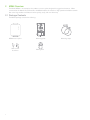
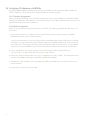
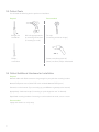
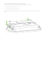
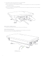
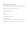
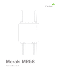
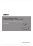
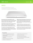
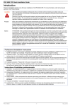
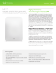
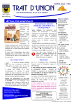
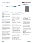
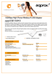
Meraki MR62/66
Hardware Installation Guide
Trademarks
Meraki, Meraki MR62, MR66, and Meraki Cloud Controller are trademarks of Meraki, Inc.
Other brand and product names are registered trademarks or trademarks of their respective holders.
Warranty
Meraki, Inc. provides a one year warranty on this product. Warranty details may be found at www.meraki.com/support.
Table of Contents
1 Scope of Document and Related Publications
4
2
5
5
6
8
9
9
9
MR66 Overview
2.1 Package Contents
2.2 Understanding the MR66
2.3 Antennas and Ports
2.4 Power Source Options
2.5 Factory Reset Button
2.6 LED Indicators and Run Dark Mode
3 Pre-Install Preparation
10
3.1 Configure Your Network in Dashboard
3.2 Check and Upgrade Firmware
3.3 Check and Configure Firewall Settings
3.4 Assigning IP Addresses to MR66s
3.4.1 Dynamic Assignment
3.4.2 Static Assignment
3.5 Collect Tools
3.6 Collect Additional Hardware for Installation
10
10
10
11
11
11
12
12
4 Installation Instructions
4.1 Choose Your Mounting Location
4.2 Install the MR66
4.2.1 Attach the Mount Plate
4.2.3 Mount the MR66
4.2.3.1 Attach Antennas
4.2.3.2 Aim Antennas
4.2.3.3 Powering the MR66 with Meraki 802.3af Power over Ethernet Injector
4.2.3.4 Powering the MR66 with an 802.3af Power over Ethernet Switch
4.2.3.5 Attach Power over Ethernet to the MR66
4.2.3.6 Attach Grounding Strap
4.4 Verify Device Functionality and Test Network Coverage
13
13
13
14
16
17
17
18
18
19
20
21
5 Troubleshooting
21
6 Regulatory Information
22
3
1 Scope of Document and Related Publications
The MR62/66 Hardware Installation Guide describes the installation procedure for the MR62 and MR66 access points.
Note: All instructions in this hardware installation guide reference the MR66 but apply equally to the MR62, except where noted.
4
Additional reference documents are available online at meraki.com/support/#documentation.
2 MR66 Overview
The Meraki MR66 is an enterprise-class, 802.11n access point designed for rugged environments. When connected to the Meraki Cloud Controller, the MR66 enables the creation of high-speed and reliable networks that cover large outdoor and industrial areas quickly, easily, and cost-effectively.
2.1 Package Contents
The MR66 package contains the following:
MR66 access point
Wall screws
& anchors
5
Mounting plate
Cable gland
Mounting straps
2.2 Understanding the MR66
Your Meraki MR66 has the following features:
LED indicators
Accessory antenna attachment holes
Mount attachment posts
(4x)
Grounding post
5 GHz
5 GHz
Factory reset button
Mount
Vent
Vent
Vent
The vent allows pressure and humidity equalization between the interior and the enviroment. This prevents
internal condensation and maintains a water proof seal.
Grounding Post
Provides an attachment point on the access point for the grounding strap (included). This post is threaded
to accept a M4 x 0.7mm bolt
6
Your MR66 mount plate has the following features:
Mounting holes (4x)
Mount plate attachment
slots (4x)
Vertical orientation mounting
strap slots (2x)
Horizontal orientation
mounting strap slots (2x)
Mount plate attachment screw
Release tab
Mount plate
ground
attachment
7
2.3 Antennas and Ports
The Meraki MR66 has two 802.11n radios (the MR62 has one radio). Each radio has two external antenna
connectors; both connectors for a particular radio should be attached to the same type of antenna. The 5 GHz
radio is used for mesh or client communication. The 2.4 GHz radio is primarily used for client communication.
However, it can also communicate with Meraki 2.4 GHz access points.
Meraki offers a number of different antennas for use with the MR66. Alternately, you may purchase
3rd party antennas for use with the MR66. Make sure they have N-type connectors and support the
proper frequency band (2.4 GHz or 5 GHz).
TOP
2.4 GHz
2.4 GHz
2.4 GHz antenna
connectors
5 GHz antenna
connectors
BOTTOM
5 GHz
5 GHz
Ethernet
and power port
8
Mount
2.4 Power Source Options
The MR66 access point can be powered using either a third-party 802.3af PoE switch or the Meraki
802.3af PoE injector (sold separately).
2.5 Factory Reset Button
The Factory Reset Button restores the MR66 to its original factory settings by deleting all configuration
information stored on the unit.
2.6 LED Indicators and Run Dark Mode
9
Your MR66 is equipped with a series of LED lights on the front of the unit to convey information about
system functionality and performance.
Signal Strength
One Light: Four Lights: Moving Lights: Flashing Lights: Fair
Strongest
Searching for Signal
Error state. May indicate bad gateway or other routing fault
Radio Power
Off: Solid Orange: Solid Green: Flashing Orange: Flashing Green: MR66 is off
MR66 is booting or trying to find a path to the internet
MR66 is fully operational and connected to the network
Firmware is upgrading
Error state. May indicate bad gateway or other routing fault
Ethernet
Off: On: Flashing: No active network connection at the Ethernet port
Active network connection at the Ethernet port
Error state. May indicate bad gateway or other routing fault
The MR66 may be operated in “Run Dark” mode for additional security and to reduce the visibility of the access point. In this mode, the LEDs will not be illuminated. This mode may be enabled through Meraki Dashboard.
3 Pre-Install Preparation
You should complete the following steps before going on-site to perform an installation.
3.1 Configure Your Network in Dashboard
Meraki recommends that you add your MR66 to a network in Dashboard before mounting it in the field. The
following is a brief overview only of the steps required to add an MR66 to your network. For detailed
instructions about creating, configuring and managing Meraki wireless networks, refer to the Meraki Cloud
Controller Manual (meraki.com/support/#documentation).
1. Login to http://dashboard.meraki.com. If this is your first time, create a new account.
2. Find the network to which you plan to add your nodes or create a new network.
3. Add your nodes to your network. You will need your Meraki order number (found on your invoice if you
ordered directly from Meraki) or the serial number of each node, which looks like Qxxx-xxxx-xxxx, and is
found on the bottom of the unit.
4. Finally, go to the map / floor plan view and place each node on the map by clicking and dragging it to
the location where you plan to mount it. You can always modify the location later.
3.2 Check and Upgrade Firmware
To ensure your MR66 performs optimally immediately following installation, Meraki recommends that you
facilitate a firmware upgrade prior to mounting your MR66.
1. Attach your MR66 to power and a wired Internet connection. See p. 17 of this document for details.
2. The MR66 will turn on and the Power LED will glow solid orange. If the unit does not require a firmware
upgrade, the Power LED will turn green within thirty seconds.
* If the unit requires an upgrade, the Power LED will begin blinking orange until the upgrade is complete,
at which point the Power LED will turn solid green. You should allow about an hour for the firmware
upgrade to complete, depending on the speed of your internet connection.
3.3 Check and Configure Firewall Settings
If your network will be located behind a firewall, it must allow outgoing connections on particular ports to
particular IP addresses in order for the MR66 to be able to seamlessly communicate with the Cloud Controller. The most current list of outbound ports and IP addresses can be found here:
http://tinyurl.com/y79une3
10
3.4 Assigning IP Addresses to MR66s
All gateway MR66s (MR66s with Ethernet connections to the LAN) must be assigned routable IP addresses.
These IP addresses can be dynamically assigned via DHCP or statically assigned.
3.4.1 Dynamic Assignment
When using DHCP, the DHCP server should be configured to assign a static IP address for each MAC address belonging to a Meraki AP. Other features of the wireless network, such as 802.1X authentication, may rely on the
property that the APs have static IP addresses.
Static IPs are assigned using the local web server on each AP. The following procedure describes how to set
the static IP:
3.4.2 Static Assignment
1. Using a client machine (e.g., a laptop), connect to the AP either wirelessly (by associating to any SSID
broadcast by the AP) or over a wired connection.
If using a wired connection, connect the client machine to the MR66 either through a PoE switch or a Meraki
PoE Injector. If using a PoE switch, plug an Ethernet cable into the MR66’s Ethernet jack, and the other end
into a PoE switch. Then connect the client machine over Ethernet cable to the PoE switch. If using a Meraki
PoE Injector, connect the MR66 to the “PoE” port of the Injector, and the client machine to the “LAN” port.
2. Using a web browser on the client machine, access the AP’s built-in web server by browsing to
http://my.meraki.com. Alternatively, browse to http://10.128.128.128.
3. Click on the “Static IP Configuration” tab. Log in. The default user name is “admin”. The default password is
the AP’s serial number, with hyphens included (e.g., Q2BD-551C-ZYW3).
4. Configure the static IP address, net mask, gateway IP address and DNS servers that this AP will use on its
wired connection.
11
5. If necessary, reconnect the AP to the LAN.
3.5 Collect Tools
You will need the following tools to perform an installation:
Required
Straight-slot
screwdriver
Recommended
Drill with appropriate bits
for mounting wall anchors
(if mounting to a wall)
Phillips
screwdriver
Tin snips
(if mounting with hose clamps)
Power screwdriver with 5/16”
(8 mm) nut driver, Phillips & flat heads
3.6 Collect Additional Hardware for Installation
Required
Network cables with RJ45 connectors long enough for your particular mounting location
802.3af PoE power source (either PoE switch or Meraki 802.3af PoE Injector)
Connection to the internet (if you are setting up your MR66 as a gateway to the internet)
Appropriately sized metal straps (if mounting to a pole larger than 3.9” in diameter)
Specialized mounting hardware if mounting to surface other than wood, stucco or stone
Recommended
Laptop with wireless to verify setup
12
4 Installation Instructions
4.1 Choose Your Mounting Location
A good mounting location is important to getting the best performance out of your MR66 access point.
Keep the following in mind:
1. The device should have unobstructed line of sight to most coverage areas. For example, if installing
in an office filled with workspaces divided by mid-height cubicle walls, installing on the ceiling or high
on a wall would be ideal.
2. Power over Ethernet supports a maximum cable length of 300 ft (100 m).
3. If being used in a mesh deployment, the MR66 should have line of sight to at least two other Meraki
devices. For more detailed instructions regarding access point location selection, reference the Meraki
Network Design Guide (meraki.com/support/#documentation).
4.The antennas should be as unobstructed as possible. Make sure that there is clearance around the MR66 for installation of all of your chosen antennas.
4.2 Install the MR66
13
For most mounting scenarios, the MR66 mount plate provides a quick, simple, and flexible means of mounting
your device. The installation should be done in two steps. First, install the mount plate to your selected location. Then attach the MR66 to the mount plate.
4.2.1 Remove the Mount Plate from the Access Point
Before installing the mount plate, you must remove it from the back of the access point.
1. Unscrew the mount plate attachment screw.
2. Lift and the mount plate release tab upwards.
.
3. While holding the mount plate release tab up, slide the mount plate off the access point in the direction shown below.
3
2
1
14
4.2.2 Attach the Mount Plate
The MR66 mount plate can be used to install your access point in a wide range of scenarios.
4.2.2.1 Wall or Solid Ceiling Mount Using Mount Plate
Using included wall anchors and screws, attach the mount plate to your mounting wall or ceiling.
It is recommended that the MR66 be mounted to a wall or solid ceiling using the mount plate for physical
security reasons.
15
4.2.3 Mount the MR66
Insert the posts on the back of the access point into the attachment slots on the mount plate.
16
4.2.3.1 Attach Antennas
Remove protective plastic covers from all four N-type RF connectors. Attach appropriate antennas (and
protective boots if included).
4.2.3.2 Aim Antennas
If you are using directional antennas, aim them appropriately to ensure optimal performance for your
specific network topography. Omnidirectional antennas perform best in a mesh network when oriented vertically.
17
4.2.3.3 Powering the MR66 with the Meraki 802.3af Power over Ethernet Injector (sold separately)
1. Plug the power cord into the PoE Injector and the other end into wall power.
2. Plug an Ethernet cable that is connected to an active Ethernet connection into the “IN“ port on the injector.
3. Route Ethernet cable from the “OUT“ port on the injector to the Ethernet port in the bay of the MR66.
For more details, see Meraki
802.3af Power Over Ethernet
Injector datasheet.
PoE
3
LAN
PoE
2
AC
1
LAN
4.2.3.4 Powering the MR66 with an 802.3af Power over Ethernet Switch
Route Ethernet cable from a port on an active 802.3af PoE switch to the Ethernet port in the bay of the MR66.
The MR66 is Gigabit Ethernet-capable. To maximize device performance, a Gigabit Ethernet-capable switch should be used.
18
4.2.3.5 Attach Power over Ethernet to the MR66
1. Route the Ethernet cable from the PoE Injector “OUT” port to the MR66.
2. Install a cable gland on the MR66 end of the cable.
19
4.
Plug the Ethernet cable into the Ethernet port of the Meraki MR66.
a. Connect the cable to the Ethernet port on the MR66.
b. Screw the gland body into the threaded hole of the port. Use an adjustable wrench to make sure the gland body is fully seated in the hole.
c. Insert the split ring gasket into the gland body.
d. Screw the cap tightly onto the gland. You may need a wrench to fully tighten the cap, but take care not to damage the cable in the process.
Optional: Make the MR66 a gateway
1. Connect an active internet connection to the “IN” port of the PoE injector.
4.2.3.6 Attach Grounding Strap
Connect one end of grounding strap to grounding post with included screw and washer.
Securely attach the other end nearby grounded structure.
Connect to
grounded structure
20
4.4 Verify Device Functionality and Test Network Coverage
1. Check LEDs
The Radio Power LED should be solid green. If it is flashing orange, the firmware is automatically upgrading and the LED should turn green when the upgrade is completed (normally in under thirty minutes). If the device is a gateway, the Ethernet LED and the four Signal Strength LEDs should be green as well. If the device is a repeater only, the Ethernet LED will not be illuminated and the number of green Signal Strength LEDs will show the signal strength to the nearest Meraki device. See section 2.6 for further details about information conveyed by the LEDs.
Note: Your MR66 must have an active route to the Internet to check and upgrade its firmware.
2. Verify access point connectivity
Use any 802.11 client device to connect to the MR66 and verify proper connectivity using the client’s web
browser.
3.Check network coverage
Confirm that you have good signal strength throughout your coverage area. You can use the signal strength meter on a laptop, smart phone, or other wireless device.
5Troubleshooting
21
Reference the Meraki knowledge base at http://meraki.com/support/#kb for additional information and
troubleshooting tips.
6 Regulatory Information for MR62
U.S. Regulatory Wireless Notice
Federal Communication Commission Interference Statement:
This equipment has been tested and found to comply with the limits for a Class B digital device, pursuant to Part
15 of the FCC Rules. These limits are designed to provide reasonable protection against harmful interference in a
residential installation. This equipment generates, uses and can radiate radio frequency energy and, if not installed
and used in accordance with the instructions, may cause harmful interference to radio communications. However,
there is no guarantee that interference will not occur in a particular installation. If this equipment does cause harmful
interference to radio or television reception, which can be determined by turning the equipment off and on, the user
is encouraged to try to correct the interference by one of the following measures:
• Reorient or relocate the receiving antenna.
• Increase the separation between the equipment and receiver.
• Connect the equipment into an outlet on a circuit different from
that to which the receiver is connected.
• Consult the dealer or an experienced radio/TV technician for help.
FCC Caution:
Any changes or modifications not expressly approved by the party responsible for compliance could void the user’s
authority to operate this equipment.
This device complies with Part 15 of the FCC Rules. Operation is subject to the following two conditions:
• this device may not cause harmful interference, and
• this device must accept any interference received, including interference that may cause undesired operation.
FCC Radiation Exposure Statement:
This equipment complies with FCC radiation exposure limits set forth for an uncontrolled environment.
This equipment should be installed and operated with minimum distance 50 cm between the radiator and your body.
This transmitter must not be co-located or operating in conjunction with any other antenna or transmitter.
IEEE 802.11b or 802.11g operation of this product in the USA is firmware-limited to channels 1 through 11.
22
Canadian Regulatory Wireless Notice
This device complies with RSS-210 of the Industry Canada Rules. Operation is subject to
the following two conditions:
• this device may not cause interference and
• this device must accept any interference received, including interference that may cause undesired operation
Ce dispositif est conforme à la norme CNR-210 d’Industrie Canada applicable aux appareils radio exempts de licence.
Son fonctionnement est sujet aux deux conditions suivantes:
• le dispositif ne doit pas produire de brouillage préjudiciable, et
• ce dispositif doit accepter tout brouillage reçu, y compris un brouillage susceptible de provoquer un fonctionnement
indésirable.
IC Radiation Exposure Statement:
This equipment complies with IC radiation exposure limits set forth for an uncontrolled environment.
This equipment should be installed and operated with minimum distance 50 cm between the radiator
and your body.
This device has been designed to operate with an antenna having a maximum gain of 11dBi. Antenna having a higher gain is strictly prohibited per regulations of Industry Canada. The required antenna impedance is 50 ohms.
Déclaration d’exposition aux radiations:
Cet équipement est conforme aux limites d’exposition aux rayonnements IC établies pour un environnement non contrôlé.
Cet équipement doit être installé et utilisé avec un minimum de 50cm de distance entre la source de rayonnement et votre
corps.
Ce dispositif a été conçu pour fonctionner avec une antenne ayant un gain maximal de 11dBi. Une antenne à gain plus
élevé est strictement interdite par les règlements d’Industrie Canada. L’impédance d’antenne requise est de 50 ohms.
This radio transmitter (IC: 6961A-60018010 / Model: 600-18010) has been approved by Industry Canada to operate
with the antenna types listed below with the maximum permissible gain and required antenna impedance for each antenna
type indicated. Antenna types not included in this list, having a gain greater than the maximum gain indicated for that type,
are strictly prohibited for use with this device.
Le present emetteur radio (IC: 6961A-60018010 / Model: 600-18010) a ete approuve par Industrie Canada pour
fonctionner avec les types d’antenne enumeres ci-dessous et ayant un gain admissible maximal et l’impedance requise
pour chaque type d’antenne. Les types d’antenne non inclus dans cette liste, ou dont le gain est superieur au gain maximal
indique, sont strictement interdits pour l’exploitation de l’emetteur.
Remark :
Antenna Information :
Omni ANT 2.4GHz : 5dBi
Sector ANT 2.4GHz : 11dBi
23
Europe – EU Declaration of Conformity
This device complies with the essential requirements of the R&TTE Directive 1999/5/EC.
The following test methods have been applied in order to prove presumption of conformity with the essential
requirements of the R&TTE Directive 1999/5/EC:
Radio:
EMC: Safety: RF Exposure: Emissions: Immunity: In Italy the end-user should apply for a license at the national spectrum authorities in order to obtain authorization
to use the device for setting up outdoor radio links and/or for supplying public access to telecommunications
and/or network services.
EN 300 328, EN 301 893
EN 301 489-1, EN 301 489-17
EN 60950-1
EN 50385
EN 55022, EN 61000-3-2, EN 61000-3-3
EN 61000-4-2, EN 61000-4-3, EN 61000-4-4, EN 61000-4-5, EN 61000-4-6, EN 61000-4-11
This device is a 2.4 GHz wideband transmission system (transceiver), intended for use in all EU
member states and EFTA countries with the following restrictions:
Česky (Czech)
Meraki, Inc. tímto prohlašuje, že tento wireless device je ve shodě se základními požadavky
a dalšími příslušnými ustanoveními směrnice.
Dansk (Danish)
Undertegnede Meraki, Inc. erklærer herved, at følgende udstyr wireless device overholder
de væsentlige krav og øvrige relevante krav i direktiv 1999/5/EF.
Deutsch (German)
Hiermit erklärt Meraki, Inc., dass sich das Gerät wireless device in Übereinstimmung mit
den grundlegenden Anforderungen und den übrigen einschlägigen Bestimmungen der
Richtlinie 1999/5/EG befindet.
Español (Spanish)
Por medio de la presente Meraki, Inc. declara que el wireless device cumple con los requisitos
esenciales y cualesquiera otras disposiciones aplicables o exigibles de la Directiva 1999/5/CE.
Ελληνική (Greek)
ΜΕ ΤΗΝ ΠΑΡΟΥΣΑ Meraki, Inc. ΔΗΛΩΝΕΙ ΟΤΙ wireless device ΣΥΜΜΟΡΦΩΝΕΤΑΙ ΠΡΟΣ ΤΙΣ
ΟΥΣΙΩΔΕΙΣ ΑΠΑΙΤΗΣΕΙΣ ΚΑΙ ΤΙΣ ΛΟΙΠΕΣ ΣΧΕΤΙΚΕΣ ΔΙΑΤΑΞΕΙΣ ΤΗΣ ΟΔΗΓΙΑΣ 1999/5/ЕΚ.
24
Eesti (Estonian)
Käesolevaga kinnitab Meraki, Inc. seadme wireless device vastavust direktiivi 1999/5/EÜ
põhinõuetele ja nimetatud direktiivist tulenevatele.
English
Hereby, Meraki, Inc., declares that this wireless device is in compliance with the essential
requirements and other relevant provisions of Directive 1999/5/EC.
Français (French)
Par la présente Meraki, Inc. déclare que l’appareil wireless device est conforme aux exigences
essentielles et aux autres dispositions pertinentes de la directive 1999/5/CE.
Italiano (Italian)
Con la presente Meraki, Inc. dichiara che questo wireless device è conforme ai requisiti essenziali
ed alle altre disposizioni pertinenti stabilite dalla direttiva 1999/5/CE.
Latviski (Latvian)
Ar šo Meraki, Inc. deklarē, ka wireless device atbilst Direktīvas 1999/5/EK būtiskajām prasībām
un citiem ar to saistītajiem noteikumiem.
Nederland (Dutch)
Hierbij verklaart Meraki, Inc. dat het toestel wireless device in overeenstemming is met de
essentiële eisen en de andere relevante bepalingen van richtlijn 1999/5/EG.
Malti (Maltese)
Hawnhekk, Meraki, Inc., jiddikjara li dan wireless device jikkonforma mal-ħtigijiet essenzjali
u ma provvedimenti oħrajn relevanti li hemm fid-Dirrettiva 1999/5/EC.
Magyar (Hungarian)
Alulírott, Meraki, Inc. nyilatkozom, hogy a wireless devicce megfelel a vonatkozó alapvetõ
követelményeknek és az 1999/5/EC irányelv egyéb elõírásainak.
Polski (Polish)
Niniejszym Meraki, Inc. oświadcza, że wireless device jest zgodny z zasadniczymi wymogami
oraz pozostalymi stosownymi
Português (Portuguese)
Meraki, Inc. declara que este wireless device está conforme com os requisitos essenciais e
outras disposições da Directiva 1999/5/CE.
Slovensko (Slovenian)
Meraki, Inc. izjavlja, da je ta wireless device v skladu z bistvenimi zahtevami in ostalimi
relevantnimi dolocili direktive 1999/5/ES.
Slovensky (Slovak)
Meraki, Inc. týmto vyhlasuje, že wireless device splna základné požiadavky a všetky príslušné
ustanovenia Smernice 1999/5/ES.
Suomi (Finnish)
Meraki, Inc. vakuuttaa täten että wireless device tyyppinen laite on direktiivin 1999/5/EY
oleellisten vaatimusten ja sitä koskevien direktiivin muiden ehtojen mukainen.
Svenska (Swedish)
Härmed intygar Meraki, Inc. att denna wireless device står I överensstämmelse med de
väsentliga egenskapskrav och övriga relevanta bestämmelser som framgår direktiv 1995/5/EG.
25
Lietuvių (Lithuanian)
Šiuo Meraki, Inc. deklaruoja, kad šis wireless device atitinka esminius reikalavimus ir kitas
1999/5/EB Direktyvos nuostatas.
Professional installation instruction
Please be advised that due to the unique function supplied by this product, the device is intended for use with our interactive entertainment software and licensed third-party only. The product will be distributed through controlled distribution
channel and installed by trained professional and will not be sold directly to the general public through retail store.
1. Installation personal
This product is designed for specific application and needs to be installed by a qualified personal who has RF and related
rule knowledge. The general user shall not attempt to install or change the setting.
2. Installation location
The product shall be installed at a location where the radiating antenna can be kept 50cm from nearby person in normal
operation condition to meet regulatory RF exposure requirement.
3. External antenna
Use only the antennas which have been approved by Meraki Inc. The non-approved antenna(s) may produce unwanted
spurious or excessive RF transmitting power which may lead to the violation of FCC/IC limit and is prohibited.
4. Installation procedure
Please refer to the rest of this manual for the detail.
5. Warning
Please carefully select the installation position and make sure that the final output power does not exceed the limit set
force in relevant rules. The violation of the rule could lead to serious federal penalty.
The following maximum Transmit powers should be observed during configuration:
Omni antenna:
802.11b:
23.7 dBm
802.11g:
27.7 dBm
802.11n 20 M: 27.7 dBm
802.11n 40 M: 27.7 dBm
Panel antenna:
802.11b:
22.5 dBm
802.11g:
27.0 dBm
802.11n 20 M: 27.0 dBm
802.11n 40 M: 25.8 dBm
At these levels the panel antenna can be used only on point to point application. Point to multi-points is not allowed, and
may require further reductions to meet local regulations.
26
Instructions d’installation professionnelle
Veuillez noter que l’appareil etant dedie a une fonction unique, il doit etre utilise avec notre logiciel proprietaire de divertissement interactif . Ce produit sera propose par un reseau de distribution controle et installe par des professionels; il ne
sera pas propose au grand public par le reseau de la grande distribution.
1. Installation
Ce produit est destine a un usage specifique et doit etre installe par un personnel qualifie maitrisant les radiofrequences
et les regles s’y rapportant. L’installation et les reglages ne doivent pas etre modifies par l’utilisateur final.
2. Emplacement d’installation
En usage normal, afin de respecter les exigences reglementaires concernant l’exposition aux radiofrequences, ce produit
doit etre installe de facon a respecter une distance de 50 cm entre l’antenne emettrice et les personnes.
3. Antenn externe
Utiliser uniiquement les antennes approuvees par le fabricant. L’utilisation d’autres antennes peut conduire a un niveau de
rayonnement essentiel ou non essentiel depassant les niveaux limites definis par FCC/IC, ce qui est interdit.
4. Procedure d’installation
Consulter le manuel d’utilisation.
5. Avertissement
Choisir avec soin la position d’installation et s’assurer que la puissance de sortie ne depasse pas les limites en vigueur. La
violation de cette regle peut conduire a de serieuses penalites federales.
27
7 Regulatory Information for MR66
U.S. Regulatory Wireless Notice
Federal Communication Commission Interference Statement:
This equipment has been tested and found to comply with the limits for a Class B digital device, pursuant to Part
15 of the FCC Rules. These limits are designed to provide reasonable protection against harmful interference in a
residential installation. This equipment generates, uses and can radiate radio frequency energy and, if not installed
and used in accordance with the instructions, may cause harmful interference to radio communications. However,
there is no guarantee that interference will not occur in a particular installation. If this equipment does cause harmful
interference to radio or television reception, which can be determined by turning the equipment off and on, the user
is encouraged to try to correct the interference by one of the following measures:
• Reorient or relocate the receiving antenna.
• Increase the separation between the equipment and receiver.
• Connect the equipment into an outlet on a circuit different from
that to which the receiver is connected.
• Consult the dealer or an experienced radio/TV technician for help.
FCC Caution:
Any changes or modifications not expressly approved by the party responsible for compliance could void the user’s
authority to operate this equipment.
This device complies with Part 15 of the FCC Rules. Operation is subject to the following two conditions:
• this device may not cause harmful interference, and
• this device must accept any interference received, including interference that may cause undesired operation.
FCC Radiation Exposure Statement:
This equipment complies with FCC radiation exposure limits set forth for an uncontrolled environment.
This equipment should be installed and operated with minimum distance 30 cm between the radiator and your body.
This transmitter must not be co-located or operating in conjunction with any other antenna or transmitter.
IEEE 802.11b or 802.11g operation of this product in the USA is firmware-limited to channels 1 through 11.
28
If this device is going to be operated in 5.15 ~ 5.25 GHz frequency range, then it is restricted in indoor environment only.
Canadian Regulatory Wireless Notice
This device complies with RSS-210 of the Industry Canada Rules. Operation is subject to
the following two conditions:
• this device may not cause interference and
• this device must accept any interference, including interference that may cause undesired operation of the device.
Ce dispositif est conforme à la norme CNR-210 d’Industrie Canada applicable aux appareils radio exempts de licence.
Son fonctionnement est sujet aux deux conditions suivantes:
• le dispositif ne doit pas produire de brouillage préjudiciable, et
• ce dispositif doit accepter tout brouillage reçu, y compris un brouillage susceptible de provoquer un fonctionnement
indésirable.
IC Radiation Exposure Statement:
This equipment complies with IC radiation exposure limits set forth for an uncontrolled environment.
This equipment should be installed and operated with minimum distance 30 cm between the radiator
and your body.
This device has been designed to operate with an antenna having a maximum gain of 14 dBi. Antenna having a higher gain
is strictly prohibited per regulations of Industry Canada. The required antenna impedance is 50 ohms.
Under Industry Canada regulations, this radio transmitter may only operate using an antenna of a type and maximum (or
lesser) gain approved for the transmitter by Industry Canada. To reduce potential radio interference to other users, the antenna type and its gain should be so chosen that the equivalent isotropically radiated power (e.i.r.p.) is not more than that
necessary for successful communication.
This radio transmitter (IC: 6961A-60019010 / Model: 600-19010) has been approved by Industry Canada to operate
with the antenna types listed below with the maximum permissible gain and required antenna impedance for each antenna
type indicated. Antenna types not included in this list, having a gain greater than the maximum gain indicated for that type,
are strictly prohibited for use with this device.
Caution:
The device for the band 5150-5250 MHz is only for indoor usage to reduce potential for harmful interference to co-chan
nel mobile satellite systems.
NOTE IMPORTANTE: (Pour l’utilisation de dispositifs mobiles)
Déclaration d’exposition aux radiations:
Cet équipement est conforme aux limites d’exposition aux rayonnements IC établies pour un environnement non contrôlé.
Cet équipement doit être installé et utilisé avec un minimum de 30 cm de distance entre la source de rayonnement et
votre corps
(Le manuel d’utilisation de dispositifs émetteurs équipés d’antennes amovibles doit contenir les informations suivantes
dans un endroit bien en vue:)
Ce dispositif a été conçu pour fonctionner avec une antenne ayant un gain maximal de dBi 14. Une antenne à gain plus
élevé est strictement interdite par les règlements d’Industrie Canada. L’impédance d’antenne requise est de 50 ohms.
Conformément à la réglementation d’Industrie Canada, le présent émetteur radio peutfonctionner avec une antenne d’un
29
type et d’un gain maximal (ou inférieur) approuvé pourl’émetteur par Industrie Canada. Dans le but de réduire les risques
de brouillage radioélectriqueà l’intention des autres utilisateurs, il faut choisir le type d’antenne et son gain de sorte que
lapuissance isotrope rayonnée équivalente (p.i.r.e.) ne dépasse pas l’intensité nécessaire àl’établissement d’une communication satisfaisante.
Le présent émetteur radio (IC: 6961A-60019010 / Model: 600-19010) a été approuvé par Industrie Canada pour fonctionner avec les types d’antenne énumérés ci-dessous et ayant un gain admissible maximal et l’impédance requise pour
chaque type d’antenne. Les types d’antenne non inclus dans cette liste, ou dont le gain est supérieur au gain maximal
indiqué, sont strictement interdits pour l’exploitation de l’émetteur.
Avertissement:
Le dispositif fonctionnant dans la bande 5150-5250 MHz est réservé uniquement pour une utilisation à l’intérieur afin de
réduire les risques de brouillage préjudiciable aux systèmes de satellites mobiles utilisant les mêmes canaux.
Remark :
Antenna Information :
2.4G N-Type Antenna @ 11dBi / PIFA; 5dBi / Dipole
5G N-Type Antenna @ 14dBi / PIFA; 7dBi / Dipole
30
Europe – EU Declaration of Conformity
This device complies with the essential requirements of the R&TTE Directive 1999/5/EC.
The following test methods have been applied in order to prove presumption of conformity with the essential
requirements of the R&TTE Directive 1999/5/EC:
Radio:
EMC: Safety: RF Exposure: Emissions: Immunity: EN 300 328, EN 301 893
EN 301 489-1, EN 301 489-17
EN 60950-1
EN 50385
EN 55022, EN 61000-3-2, EN 61000-3-3
EN 61000-4-2, EN 61000-4-3, EN 61000-4-4, EN 61000-4-5, EN 61000-4-6, EN 61000-4-11
In Italy the end-user should apply for a license at the national spectrum authorities in order to obtain authorization
to use the device for setting up outdoor radio links and/or for supplying public access to telecommunications
and/or network services.
The device may not be used in the 5 GHz spectrum unless the 5.725 - 5.875 GHz has been disabled.
This can be done through the Meraki Dashboard.
This device is a 2.4 GHz and 5 GHz wideband transmission system (transceiver), intended for use in all EU
member states and EFTA countries with the following restrictions:
Česky (Czech)
Meraki, Inc. tímto prohlašuje, že tento wireless device je ve shodě se základními požadavky
a dalšími příslušnými ustanoveními směrnice.
Dansk (Danish)
Undertegnede Meraki, Inc. erklærer herved, at følgende udstyr wireless device overholder
de væsentlige krav og øvrige relevante krav i direktiv 1999/5/EF.
Deutsch (German)
Hiermit erklärt Meraki, Inc., dass sich das Gerät wireless device in Übereinstimmung mit
den grundlegenden Anforderungen und den übrigen einschlägigen Bestimmungen der
Richtlinie 1999/5/EG befindet.
Español (Spanish)
Por medio de la presente Meraki, Inc. declara que el wireless device cumple con los requisitos
esenciales y cualesquiera otras disposiciones aplicables o exigibles de la Directiva 1999/5/CE.
Ελληνική (Greek)
ΜΕ ΤΗΝ ΠΑΡΟΥΣΑ Meraki, Inc. ΔΗΛΩΝΕΙ ΟΤΙ wireless device ΣΥΜΜΟΡΦΩΝΕΤΑΙ ΠΡΟΣ ΤΙΣ
ΟΥΣΙΩΔΕΙΣ ΑΠΑΙΤΗΣΕΙΣ ΚΑΙ ΤΙΣ ΛΟΙΠΕΣ ΣΧΕΤΙΚΕΣ ΔΙΑΤΑΞΕΙΣ ΤΗΣ ΟΔΗΓΙΑΣ 1999/5/ЕΚ.
Français (French)
Par la présente Meraki, Inc. déclare que l’appareil wireless device est conforme aux exigences
essentielles et aux autres dispositions pertinentes de la directive 1999/5/CE.
31
Eesti (Estonian)
Käesolevaga kinnitab Meraki, Inc. seadme wireless device vastavust direktiivi 1999/5/EÜ
põhinõuetele ja nimetatud direktiivist tulenevatele.
English
Hereby, Meraki, Inc., declares that this wireless device is in compliance with the essential
requirements and other relevant provisions of Directive 1999/5/EC.
Italiano (Italian)
Con la presente Meraki, Inc. dichiara che questo wireless device è conforme ai requisiti essenziali
ed alle altre disposizioni pertinenti stabilite dalla direttiva 1999/5/CE.
Latviski (Latvian)
Ar šo Meraki, Inc. deklarē, ka wireless device atbilst Direktīvas 1999/5/EK būtiskajām prasībām
un citiem ar to saistītajiem noteikumiem.
Lietuvių (Lithuanian)
Šiuo Meraki, Inc. deklaruoja, kad šis wireless device atitinka esminius reikalavimus ir kitas
1999/5/EB Direktyvos nuostatas.
Nederland (Dutch)
Hierbij verklaart Meraki, Inc. dat het toestel wireless device in overeenstemming is met de
essentiële eisen en de andere relevante bepalingen van richtlijn 1999/5/EG.
Malti (Maltese)
Hawnhekk, Meraki, Inc., jiddikjara li dan wireless device jikkonforma mal-ħtigijiet essenzjali
u ma provvedimenti oħrajn relevanti li hemm fid-Dirrettiva 1999/5/EC.
Magyar (Hungarian)
Alulírott, Meraki, Inc. nyilatkozom, hogy a wireless devicce megfelel a vonatkozó alapvetõ
követelményeknek és az 1999/5/EC irányelv egyéb elõírásainak.
Polski (Polish)
Niniejszym Meraki, Inc. oświadcza, że wireless device jest zgodny z zasadniczymi wymogami
oraz pozostalymi stosownymi
Português (Portuguese)
Meraki, Inc. declara que este wireless device está conforme com os requisitos essenciais e
outras disposições da Directiva 1999/5/CE.
Slovensko (Slovenian)
Meraki, Inc. izjavlja, da je ta wireless device v skladu z bistvenimi zahtevami in ostalimi
relevantnimi dolocili direktive 1999/5/ES.
Slovensky (Slovak)
Meraki, Inc. týmto vyhlasuje, že wireless device splna základné požiadavky a všetky príslušné
ustanovenia Smernice 1999/5/ES.
Suomi (Finnish)
Meraki, Inc. vakuuttaa täten että wireless device tyyppinen laite on direktiivin 1999/5/EY
oleellisten vaatimusten ja sitä koskevien direktiivin muiden ehtojen mukainen.
Svenska (Swedish)
Härmed intygar Meraki, Inc. att denna wireless device står I överensstämmelse med de
väsentliga egenskapskrav och övriga relevanta bestämmelser som framgår direktiv 1995/5/EG.
32
Professional installation instruction
Please be advised that due to the unique function supplied by this product, the device is intended for use with our interactive entertainment software and licensed third-party only. The product will be distributed through controlled distribution
channel and installed by trained professional and will not be sold directly to the general public through retail store.
1. Installation personal
This product is designed for specific application and needs to be installed by a qualified personal who has RF and related
rule knowledge. The general user shall not attempt to install or change the setting.
2. Installation location
The product shall be installed at a location where the radiating antenna can be kept 30cm from nearby person in normal
operation condition to meet regulatory RF exposure requirement.
3. External antenna
Use only the antennas which have been approved by Meraki Inc. The non-approved antenna(s) may produce unwanted
spurious or excessive RF transmitting power which may lead to the violation of FCC/IC limit and is prohibited.
4. Installation procedure
Please refer to the rest of this manual for the detail.
5. Warning
Please carefully select the installation position and make sure that the final output power does not exceed the limit set
force in relevant rules. The violation of the rule could lead to serious federal penalty.
The following maximum Transmit powers should be observed during configuration:
Panel antenna:
802.11b:21.99 dBm
802.11g:21.96 dBm
802.11n 20 M: 24.93 dBm
802.11n 40 M: 24.71 dBm
802.11a 5180-5240 MHz: 5.91 dBm
802.11n 20 MHz 5180-5240 MHz: 8.68 dBm
802.11n 40 MHz 5180-5240 MHz: 8.90 dBm
802.11a 5745-5825 MHz: 19.3 dBm
802.11n 5745-5825 MHz: 21.95 dBm
802.11n 5745-5825 MHz: 21.84 dBm
33
Dipole antenna:
802.11b:24.38 dBm
802.11g:27.84 dBm
802.11n 20 M: 27.82 dBm
802.11n 40 M: 26.0 dBm
802.11a 5180-5240 MHz: 12.98 dBm
802.11n 20 MHz 5180-5240 MHz: 15.95 dBm
802.11n 40 MHz 5180-5240 MHz: 15.99 dBm
802.11a 5745-5825 MHz: 25.89 dBm
802.11n 5745-5825 MHz: 28.05 dBm
802.11n 5745-5825 MHz: 28.9 dBm
At these levels the panel antenna can be used only on point to point application. Point to multi-points is not allowed, and
may require further reductions to meet local regulations.
Instructions d’installation professionnelle
Veuillez noter que l’appareil etant dedie a une fonction unique, il doit etre utilise avec notre logiciel proprietaire de divertissement interactif . Ce produit sera propose par un reseau de distribution controle et installe par des professionels; il ne
sera pas propose au grand public par le reseau de la grande distribution.
1. Installation
Ce produit est destine a un usage specifique et doit etre installe par un personnel qualifie maitrisant les radiofrequences
et les regles s’y rapportant. L’installation et les reglages ne doivent pas etre modifies par l’utilisateur final.
2. Emplacement d’installation
En usage normal, afin de respecter les exigences reglementaires concernant l’exposition aux radiofrequences, ce produit
doit etre installe de facon a respecter une distance de 30 cm entre l’antenne emettrice et les personnes.
3. Antenn externe
Utiliser uniiquement les antennes approuvees par le fabricant. L’utilisation d’autres antennes peut conduire a un niveau de
rayonnement essentiel ou non essentiel depassant les niveaux limites definis par FCC/IC, ce qui est interdit.
4. Procedure d’installation
Consulter le manuel d’utilisation.
5. Avertissement
Choisir avec soin la position d’installation et s’assurer que la puissance de sortie ne depasse pas les limites en vigueur. La
violation de cette regle peut conduire a de serieuses penalites federales.
34
35
www.meraki.com
660 Alabama St.
San Francisco, California 94110
Phone: +1 415 632 5800
Fax: +1 415 632 5890
36