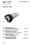
1
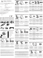
3 enjoy-motors ® Programación del final de carrera Inferior - Down Limit siwtch adjustment - Determinazione dei punti di fine corsa Inferiore - Programmation des fins de course Inférieur 1 EC DECLARATION OF CONFORMITY Jolly Motor España, S.L. Incolla, 1 46370 Chiva Valencia Spain Product: Tubular Motor Type Designation: JE 50/10; JE 50/20; JE 50/30; JE 50/40; JE 50/50 (Radio) JE 50/20; JE 50/30; JE 50/40; JE 50/50 (Sun) JE 50/40; JE 50/50 (SunSF) The designated product is in conformity with the European Directive: 2006/95/EC “Council Directive on harmonization of laws of the Member States relating to electrical equipment designed for use within certain voltage limits”. The technical documentation and full compliance with the standards lsited bellow proves the conformity of the product with the requirements of above-mentioned EC Directive: Last two digits of the year in which the CE marking was affixed: DIN EN 60335-1:2007-02; EN 60335-1:2002+A11+A1+A12+Corr.+A2:2006 DIN EN 60335-1/A12:2009-05; EN 60335-1/A13:2008 DIN EN 60335-2-97:2009-10; EN 60335-2-97:2006+A11:2008 DIN EN 62233:2008-11; EN 62233:2008 DIN EN 62233 Ber. 1:2009-04; EN 62233 Ber. 1:2008 El primer final de carrera debe ser el inferior (persiana cerrada o toldo abierto). Parar el motor en el punto inferior deseado Seguidamente pulsar 1 VEZ el botón P3. The first limit switch point to be set up is the lower one (roller shutter closed or sun blind open). Stop the motor when it reach the down wished limit point Immediately press 1 TIME P3 button Then the motor will make a single tilt movement Il primo punto di fine corsa ad essere determinato deve essere quello inferiore (tapparella chiusa o tenda aperta). Fermi il motore a il punto inferiore desiderato Premere immediatamente il tasto P3 1 VOLTA Quindi il motore farà un singolo movimento di conferma su e giù El motor realiza un movimiento en cada sentido. La descente est la première fin de Attendez que le moteur fasse un course à positionner (volet roulant signal sonore et réalise un moufermé ou store banne ouvert). Appuyez 1 FOIS sur le bouton P3 vement dans chaque sens pour Arrêter le moteur lorsque qu'il confirmer atteindra le point inférieur 4 Programación del final de carrera Superior - Up Limit siwtch adjustment - Determinazione dei punti di fine corsa Superiore- Programmation des fins de course Supérieur Copia de nuevos Emisores - New Emitters enablement - Associazione di nuovi Trasmittenti Copie d'un nouvel Émetteur 1 1 46370 · Chiva · Valencia · España (Spain) · Tel. +34 962 521 490 · [email protected] · www.enjoy-motors.com Issuer´s name and address: 7 1 Emisor Original: pulsar 1 VEZ el botón P3. 2 Esperar a que el motor emita un pitido, y realice un movimiento en cada sentido 1 1 Emisor Original: Pulsar 1 VEZ el botón de Subida Emisor Nuevo: Pulsar 1 VEZ el botón de Subida Esperar a que el motor emita un nuevo pitido, y realice dos movimientos Wait till the motor will New Emitter: sound another time Press 1 TIME UP and makes a double button tilt movement Master Emitter: Then the motor will Master Emitter: Press 1 TIME P3 make sound BIB a Press 1 TIME UP button single tilt movement button Quindi il motore Quindi il motore Trasmittente Master: Trasmittente Master: Trasmittente Nuovo: emetterà un suono e emetterà un suono e Premere il tasto P3 Premere1 VOLTA il Premere 1 VOLTA il farà un singolo movifarà due movimenti 1 VOLTA tasto salita tasto salita mento di conferma di conferma Attendez que le Attendez que le moteur délivre un l'Émetteur Initial: l'Émetteur Initial: l'Émetteur Nouvel: moteur bip fasse un nouveau bip, et Appuyez 1 FOIS sur Appuyez 1 FOIS sur Appuyez 1 FOIS sur mouvement dans fasse deux mouvele bouton P3 le bouton de montée le bouton de montée chaque direction ments de confirmation 8 Cancelación de un Emisor - Emitter Cancellation - Cancellazione di un Trasmittori Annulation d'un nouvel Émetteur Chiva, 26th May, 2010 Place, Date Legally binding signature of the issuer motor B46470019 Type Nm Rpm Load min V-Hz W A IP JE 50/10 Radio 10 13 20 4 230-50 136 0,60 44 JE 50/20 Radio-Sun 20 13 40 4 230-50 155 0,68 44 JE 50/30 Radio-Sun 30 13 60 4 230-50 203 0,84 44 JE 50/40 Radio-Sun-SunSF 40 13 80 4 230-50 226 0,95 44 JE 50/50 Radio-Sun-SunSF 50 13 100 4 230-50 244 1,06 44 1 jolly españa s.l. 1 1 Después realizamos el final de carrera Superior (persiana abierta o toldo cerrado). Parar el motor en el punto superior deseado Seguidamente pulsar 1 VEZ el botón P3. El motor realiza un movimiento en cada sentido. After that we have to set up the uper one (roller shutter open or sun blind closed). Stop the motor when it reach the up wished limit point Immediately press 1 TIME P3 button Then the motor will make a single tilt movement Il secondo punto di fine corsa ad essere determinato deve essere quello superiore (tapparella aperta o tenda chiusa). Fermi il motore a il punto superiore desiderato Premere immediatamente il tasto P3 1 VOLTA Quindi il motore farà un singolo movimento di conferma su e giù Le seconde fin de course à posiAttendez que le moteur fasse un tionner est la montée (volet rousignal sonore et réalise un moulant ouvert ou store banne fermé). Appuyez 1 FOIS sur le bouton P3 vement dans chaque sens pour Arrêter le moteur lorsque qu'il confirmer atteindra le point supérieur 2 1 3 Esperar a que el motor Esperar a que el motor En el Emisor a cancelar: En el Emisor a cancelar: emita un pitido, y realice emita un nuevo pitido, y pulsar 3 VECES el botón Pulsar 1 VEZ el botón de un movimiento en cada realice dos movimientos P3 Subida sentido de confirmación Wait till the motor will Then the motor will make Immediately press 1 TIME sound another time and In the emitter to cancel, sound BIB a single tilt UP button inside the makes a double tilt press 3 TIMES P3 button movement emitter to cancel movement En el transmette a cancellare, Premere il tasto P3 3 VOLTE Quindi il motore emetterà un suono e farà un singolo movimento di conferma En el transmette a Quindi il motore emetterà cancellare, premere1 un suono e farà due moviVOLTA il tasto salita menti di conferma Attendez que le moteur Attendez que le moteur Prendre l'émetteur à Sur l'émetteur à annuler: délivre un bip, et fasse un délivre un nouveau bip, et annuler: appuyez 3 FOIS appuyer 1 FOIS sur la mouvement dans chaque fasse deux mouvements sur le bouton P3 montée direction de confirmation 9 Reconocimiento nuevo Emisor Master - Master Emitter Replacement - Sostituzione della Transmittente Master - Remplacement de l'Emetteur Master 5 N L N L 230 V a.c. 8 Hilo Amarillo/Verde: conexión a tierra Hilo Azul: neutro de alimentación eléctrica Hilo Marrón: fase de alimentación eléctrica Press 8 TIMES P3 button. In the 8th Time, keep press ... 8 1 2 Premere per 8 VOLTE il P3. Nella ottavo tempo, mantenere premere il pulsante ... ...then the motor will do 1 tilt movement, keep pressed the button till ... ... the motor will do another 2 tilt movement ... il motore farà 1 movimento ... che il motore farà 2 ulteriori tilt su e giu, mantenere premere il movimenti tilt pulsante fino a ... ... le moteur exercera 1 mouveAppuyez 8 FOIS sur le bouton P3 ment dans chaque sens, gardez ... le moteur exercera 2 mouveet dans la 8ème fois, gardez appuappuyez le bouton jusqu'à ce qu'i ments dans chaque sens yez ... ... ...then the motor will do 1 tilt movement, keep pressed the button till ... ... the motor will do another 2 tilt movement ... il motore farà 1 movimento ... che il motore farà 2 ulteriori tilt su e giu, mantenere premere il movimenti tilt pulsante fino a ... ... le moteur exercera 1 mouveAppuyez 8 FOIS sur le bouton P3 ment dans chaque sens, gardez ... le moteur exercera 2 mouveet dans la 8ème fois, gardez appuappuyez le bouton jusqu'à ce qu'i ments dans chaque sens yez ... ... ... le moteur exercera 1 mouveAppuyez 8 FOIS sur le bouton P3 ment dans chaque sens, gardez ... le moteur exercera 2 mouveet dans la 8ème fois, gardez appuappuyez le bouton jusqu'à ce qu'i ments dans chaque sens yez ... ... 6 4 1 Posicionar la persiana en el punto El motor realiza un movimiento en Pulsar 4 VECES el botón de Stop intermedio deseado cada sentido Stop the motor when it reach the up/down wished intermediate limit point Immediately press 4 TIMES STOP button Then the motor will make a single tilt movement Fermi il motore una volta raggiunto il punto desiderato Prema immediatamente il tasto stop per 4 VOLTE A questo punto il motore farà un movimento di conferma Appuyez 4 FOIS sur le bouton STOP Attendez que le moteur fasse un signal sonore et réalise un mouvement dans chaque sens pour confirmer En montée ou descente, arrêter le moteur lorsque qu'il atteindra le point souhaité en appuyant sur le stop del final de carrera - Limit siwtch adjustment - Determinazione dei punti di fine corsa Programación Programmation des fins de course ATENCIÓN: Cuando programamos los finales de carrera, puede ocurrir que la dirección de las flechas del emisor no se corresponden con la dirección en que se mueve la persiana. En cualquier caso, seguir las instrucciones, ya que el sentido de giro se ajustará a los botones del emisor, cuando la programación haya concluido. ATTENTION: When programming the end run points, one may find that the direction of the arrows on the remote control does not correspond with the actual direction in which the roller shutter/blind moves. In any case, please follow the instructions above: the direction will automatically coincide once the procedure has been completed. ATTENZIONE: Potrebbe essere che durante le fasi di programmazione ad un comando di salita l’applicazione scenda o viceversa, seguendo le nostre istruzioni, il software provvederà automaticamente a correggere il censo di rotazione . ATTENTION: Lors de la programmation des fins de course, on peut constater que le sens des flèches de la télécommande ne correspond pas à la direction réelle dans laquelle les volets roulants / stores Banne évoluent. En tout cas, suivre les instructions ci-dessus: la direction va automatiquement coïncider dès que la procédure sera achevée. 2 Esperar a que el motor emita Desconectar el motor de un nuevo pitido (en un periodo Seguidamente pulsar 4 corriente. entre los 4 seg. y 4 min.), y VECES el botón P3 en el Volver a conectarlo, pasados realice dos movimientos de nuevo emisor a reconocer unos segundos (emitirá un confirmación de entrada en como Master. pitido) memorización Esperar a que el motor emita un nuevo pitido, y realice dos movimientos de confirmación Wait till the motor will sound Switch Off the power (only in another time (between 4 sec. Immediately press 4 TIMES and 4 min.) and makes a the main motor). P3 button, inside the New Switch on the power, after double tilt movement (at the Emitter (it is enablement as some seconds the motor will moment the motor is ready to the New Master Emitter) enablement a new Master be sound Emitter) Wait till the motor will sound another time and makes a double tilt movement Aspetti fino a che il motore Si prema immediatamente il farà un nuovo segnale sonoro Si tolga l’alimentazione al tasto P3 durante questi (tra 4 secondi a 2 minuti) e Quindi il motore emetterà un motore. Si risalimenti il motore movimenti su e giù e la farà un doppio movimento; in suono e farà due movimenti di e dopo pochi secondi si trasmittente verrà abbinata quel momento il motore è conferma sentirà un segnale sonoro come pronto a riconoscere una nuova master nuova trasmittente master Attendez que le moteur délivre un nouveau bip (entre 4 sec. Débranchez le moteur. Puis appuyez 4 FOIS sur le et 2 min.) et fasse deux mouAttendez que le moteur délivre Rebrancher le après quelques bouton P3 du nouvel émetteur vements de confirmation, au un nouveau bip, et fasse deux secondes. (reconnaissance comme moment le moteur est prêt à mouvements de confirmation Le moteur fera un bip. l'émetteur maître) l'habilitation d'un nouveau Master émetteur Programación del punto Intermedio - Mid-Point adjustment - Determinazioni dei punto Intermedio Programmation du Mi-Parcours ... el motor realiza 1 movimienPulsar 8 VECES el botón P3 y ... el motor realice 2 movimiento en cada sentido, mantener pulmantener pulsado en la 8ª ... tos en cada sentido sado hasta que ... Premere per 8 VOLTE il P3. Nella ottavo tempo, mantenere premere il pulsante ... 2 Fil Jaune/Vert: fil de terre N Fil Bleu: neutre de l’alimentation L Fil Marron: phase de l’alimentation 8 Press 8 TIMES P3 button. In the 8th Time, keep press ... 1 ... el motor realiza 1 movimienPulsar 8 VECES el botón P3 y ... el motor realice 2 movimiento en cada sentido, mantener pulmantener pulsado en la 8ª ... tos en cada sentido sado hasta que ... Habilitar Modo Programación - Enable Programming Mode - Attiva Modalità di Programmazione Activer le Mode de Programmation 8 8 8 Filo Giallo/Verde: collegamento di terra N Filo Azzurro: neutro dell’alimentazione elettrica L Filo Marrone: fase dell’alimentazione elettrica Grün / Gelb: Schutzleiter / PE N Blau: Neutralleiter / N L Braun: Phase Richtung 2 switch off switch on 4 Conexión eléctrica - Electric connections - Collegamento elettrico - Connexions électriques Elektrischer anschluss Yellow/Green cable: ground connection N Blue cable: neutral of the electrical supply L Brown cable: phase of the electrical supply 2 Cancelación de los finals de carrea - Limit siwtch deleting - Cancellacioni dei punti di fine corsa Superiore- Annulation des fins de course Exclusión sensor solar - Sun sensor exclusion - Exclusione di sensore solare - l'Exclusion du capteur 10 solaire Sun/SunSF 1 1 ff no su on n su ff no su on n su 1 1 Sun y SunSF son suministrados con el mando RTXQ868S03 Sun On: para activar Sun Off: para desactivar El motor realiza un movimiento en cada sentido Sun and SunSF are supplied with transmitter RTXQ868S03 Sun On: to active Sun Off: to disarm Then the motor will make a single tilt movement Sun e SunSF vengono forniti con la transmittente RTXQ868S03 Sun On: per attivare Sun Off: para disattivare A questo punto il motore farà un movimento di conferma Sun et SunSF sont fournis avec l'émetteur RTXQ868S03 Sun On: pour activer Sun Off: pour effacer Attendez que le moteur fasse un mouvement dans chaque sens Toldo Cofre: Final de carrera Superior - Boxed Awning: Up limit switch - Tenda Cassonata: Fine Fins de course Supérieur 11 corsa Superiore - Cofre (store): Una vez programado el punto intermedio, la persiana llegará hasta él si estando en cualquier otra posición mantenemos pulsado el botón de Stop hasta que el motor empiece a moverse (± 4 segundos). Para variar la posición del punto, únicamente es necesario repetir el procedimiento anterior en la posición deseada (sin necesidad de eliminarlo primero) After programmed the midpoint, the shutter will goes to this point, pressing and keep pressing the Stop button till the motor start to move (± 4 sec). If is needed change the middles position, you can make it as the above instructions without cancel the precedent position (just only make a new one) Una volta programmato il terzo punto di fine corsa il motore lo raggiungerà semplicemente, tenendo premuto il tasto stop fino a che il motore partirà ( circa 4 secondi ). Se è necessario cambiare la posizione parte centrale, lo si può fare come le istruzioni di cui sopra, senza cancellare la posizione precedente (solo solo fare uno nuovo) Après avoir programmé le point intermédiaire, pour obtenir un autre point intermédiaire, appuyer et maintenir la pression sur le bouton Stop jusqu'à ce que le moteur réalise un mouvement (± 4 sec). Pour modifier la position intermédiaire, il n'est pas nécessaire d'annuler le poste précédent (réaliser juste ce nouveau réglage) SunSF 1 1 Parar el motor 15cm antes del cierre El motor realiza un movimiento en cada Seguidamente pulsar 1 VEZ el botón P3. total del cofre sentido Stop the motor 15cm before the total boxed awning clousure Immediately press 1 TIME P3 button Then the motor will make a single tilt movement Fermi il motore 15cm prima della totale chiusura de la tenda Premere immediatamente il tasto P3 1 VOLTA A questo punto il motore farà un movimento di conferma Arrêter le moteur 15 cm avant la totale fermeture du cofre Appuyez 1 FOIS sur le bouton P3 Attendez que le moteur fasse un mouvement dans chaque sens radio868_multi_language_ver.1_31052010 1- Introducción e Instrucciones de Seguridad para la Instalación El “Motor Radio”, cuenta con un Español Cada motor puede reconocer hasta un máximo de 48 canales diferentes pertenecientes a emisores prestaciones. compatibles. El primer emisor memorizado (MASTER) puede utilizarse para instalar tanto los finales de carrera como memorizar o cancelar canales de la memoria. El emisor es a todos los efectos una verdadera llave, porque posee un código de identificación propio que puede ser reconocido solamente por el receptor o los receptores habilitados, y envía señales codificadas. El motor SF reduce automáticamente la velocidad de avance del toldo o de la persiana a medida que se acerca al tope mecánico, para que el cierre sea suave y completo. Todos los Motores Radio, están disponibles con un adaptador especial, con el que el motor se parará en el caso que el toldo o de la persiana sean obstaculizados. Una instalación incorrecta puede causar lesiones graves. Seguir las instrucciones de instalación No permitir a los niños que jueguen con los dispo- Nuestros motorreductores están previstos y dimensionados exclusivamente para accionar sitivos de control. Mantener a los niños lejos de persianas, pequeñas cortinas metálicas en el los controles remotos. ámbito privado y toldos para el sol. Para destinar Antes de instalar el motoreductor, quitar todos los el motorreductor a otros usos es necesario conaccesorios inútiles y dejar fuera de servicio todo sultar previamente con el fabricante y recibir la el equipo que no sea necesario para un funcionaautorización de éste. Se solicita expresamente miento motorizado. seguir las normas DIN18073. Las partes de movimientos del motor, instaladas a una altura menor de 2,5 m del suelo deben estar Nuestros motores están dimensionados correctamente y su funcionamiento es compatible con protegidas. las caracteristicas de los elementos motorizados, En la instalación de toldos, se debe prestar atensi se respetan las cargas de funcionamiento señación a dejar un espacio de al menos 40 cm entre ladas en la tablas: "Diagrama de aplicación para el toldo completamente desplegado y cualquier persianas enrollables" y "Diagrama de aplicación objeto. para toldos". No perforar el tubo con el motor en su interior. La Desconectar la corriente cuando se trabaja cerca fijación de los tirantes en las persianas y las grade los mandos. pas en los toldos deberá realizarse utilizando tornillos cuya longitud garantice que la parte Si el motor se monta en un cajón, éste debe tener una tapa de registro de inspección conforme a las saliente en el interior del tubo sea como máximo normas DIN para permitir regulaciones y controde 1 mm, con el fín de evitar interferencias mecáles del equipo. nicas entre la parte fija y la parte rotativa. 2- Procedimiento de Instalación Œ Ž Si es necesario, fijar el perno cuadrado (2) en el final de carrera (3) por medio del tornillo (4). Insertar el anillo adaptador (5) y la polea (6) y fijar esta última con la chaveta (7). Introducir la contera (9) en el tubo (10). Introducir completamente el motor (11) en el tubo de enrollado (10) SIN GOLPEAR el perno cuadrado (2). Situar el tubo motorizado en los soportes fijos (12) y (13). NO FORZANDO nunca el del lado del motor. 3- Conexiones Eléctricas La conexión de la línea al cuadro general deberá Si el cable de alimentación de este aparato estu- efectuarse con un protector bipolar cuya distancia viese dañado, deberá ser sustituido sólo por aquede apertura entre los contactos sea de 3 mm. llos establecimientos de reparación reconocidos por el fabricante, puesto que son necesarias El motorreductor esta preparado para un funcioherramientas especiales. En caso contrario la namiento intermitente. De todos modos posee en garantía pierde vigencia. su interior una protección térmica, la cual interrumpe la alimentación eléctrica en caso de sobreca- Para la instalación del motor donde el hilo es exterlentamiento, por ejemplo: un funcionamiento conno, tendrá que utilizarse el cable especifico 05RNtinuado (más de 10 veces consecutivas). F (que podrá solicitar al fabricante), o bien, será necesario proteger el cable estándar en P.V.C. La vuelta al funcionamiento del motor llega des(que viene incluido con el motor) introduciéndolo pués de un tiempo no inferior a 10 minutos, al final en tubos específicos para protegerlo de los agende los cuales la protección térmica se reanuda tes atmosféricos. automáticamente. Sin embargo, nada más reanudada, el motor debe funcionar de forma breve; el El hilo de la antena que se encuentra en el final de carrera (lateral al cable de alimentación), se debe funcionamiento regular del mismo será posible situar en el interior del cajón extendiendolo todo lo solo después del completo enfriamiento del motor posible, evitando que pueda entrar en contacto (alrededor de 60 minutos). con las partes en movimiento. En caso necesario se puede colocar con un trozo de cinta adhesiva. Si hay interferencias en la linea de alimentación, se aconseja instalar un filtro fabricado a tal efecto. 1- Safety & installation instructions English The “Radio Motor”, comprises a tubular motor with an electronic limit switch and is equipped with a high performance radio-receiving system and a remote control. The latter is used to activate one or more motors, to adjust the end run points and to create or change centralised systems. Each remote control can in fact control a virtually unlimited number of “Radio motors” and each limit switch can recognise up to a maximum of 31 different remote controls (64 channels). The remote control is key to all effects, as it possesses its own ID code that can only be recognised by the receiver/s that have deliberately been enabled for this purpose and which send encoded signals using the Rolling Code system. The “SunSF” motors, automatically slows the advancement speed of the blind when it is close to the mechanical ledge, so that the blind closes gently and completely. All the “Radio Motors”, also are availables with an special adaptor, which stops the motor if the movement of the tube is accidentally obstructed. ll “Motori Radio” è composto da un fine corsa elettronico dotato di sistema radio-ricevente ad elevate prestazioni e da un telecomando. Tramite quest’ultimo è possibile azionare uno o più motoriduttori, eseguire la regolazione dei punti di fine corsa ed infine creare e modificare sistemi centralizzati. Ogni telecomando può infatti comandare un numero virtualmente illimitato di “Motori Radio” ed ogni fine corsa può riconoscere fino ad un massimo di 31 telecomandi differenti (64 canali). Il telecomando è a tutti gli effetti una vera e propria chiave, in quanto possiede un proprio codice identificativo riconoscibile solamente dal o dai ricevitori volutamente abilitati a ciò ed invia segnali codificati con sistema “Rolling Code”. Il motore “SunSF” riduce automaticamente la velocità di avanzamento della tenda in prossimità del punto di battuta meccanica, in modo da consentire una chiusura dolce e completa. Tutti i “Motori Radio” sono disponibili con uno adattatore speciale, che provvede ad arrestare il motore nel caso in cui il movimento del tubo avvolgitore venga accidentalmente ostacolato. Un’installazione non corretta può condurre a gravi lesioni. Seguire tutte le istruzioni d’installazione Non permettere ai bambini di giocare con i dispo- I nostri motoriduttori sono previsti e dimensionati esclusivamente per l’azionamento di tapparelle, sitivi di controllo. Tenere lontani i bambini da telepiccole serrande nell’ambito privato e tende da comandi. sole. Altri utilizzi del motoriduttore devono essere Prima di installare il motoriduttore, rimuovere discussi anticipatamente con il produttore e tutte le corde inutili e mettere fuori servizio tutto richiedono il benestare di quest’ultimo. Viene l’equipaggiamento non necessario per un funziochiesto espressamente di seguire le norme DIN namento motorizzato. 18073. Nell’installazione delle tende, prestare attenzione a lasciare uno spazio di almeno 40 cm tra la tenda I nostri motori sono dimensionati correttamente ed il loro funzionamento è compatibile con le completamente dispiegata e un qualsiasi oggetcaratteristiche delle parti condotte, purché siano to. rispettati i carichi di funzionamento riportati nelle Le parti di movimento del motore installate ad tabelle: “Diagramma di applicazione per persiane un’altezza minore di 2,5 m dal pavimento devono avvolgibili” e “Diagramma di applicazione per essere protette. tende da sole”. Non forare il tubo con il motoriduttore inserito. Il Staccare la corrente quando si lavora nelle vicifissaggio dell’elemento mobile dovrà essere fatto nanze degli azionamenti, per esempio quando si utilizzando viti di lunghezza tale da garantire che lavano le finestre. la parte sporgente all’interno del tubo sia al max 1 mm, al fine di evitare interferenze meccaniche tra Se il motore viene montato in un cassonetto, questo deve avere uno sportello (portina di revisione) le parti fisse e quelle ruotanti. in base alle norme DIN, per permettere regolazioni e controlli all’impianto. 2-Procedura di Montaggio Œ Se necessario, fissare il perno quadro (2) al fine corsa (3) per mezzo della vite (4). Inserire l’anello adattatore (5) e la puleggia (6) appropriati e fissare quest’ultima con la coppiglia (7) (serie 40 e 50) oppure mediante la rondella (9) (serie 60). Ž Inserire la calotta (10) nel tubo (11). Inserire completamente il motore (12) nel tubo (11) SENZA BATTERE sul perno quadro (2). Agganciare il tubo agli appositi supporti fissi (13) e (14). NON FORZARE durante l’aggancio del lato motore e posizionare il tubo in modo che le viti di regolazione (15) siano facilmente raggiungibili. 3- Collegamento Elettrico La connessione alla linea (nel quadro generale) Se il cavo di alimentazione dell’apparecchio è dan- deve essere fatta con un deviatore bipolare con neggiato, deve essere sostituito solo da un ufficio una distanza d’apertura di 3 mm tra i contatti. riparazione riconosciuto dal fabbricante, in quanto sono necessari attrezzi particolari. In caso contra Il motoriduttore è stato progettato per un funzionario la garanzia decadrà. mento intermittente. E’ comunque provvisto al suo interno di una protezione termica che interrompe Per installazioni del motore dove il filo è esterno, l’alimentazione elettrica in caso di surriscaldamendeve essere utilizzato il cavo speciale 05RN-F (da to, ad esempio in seguito ad azionamenti continui chiedere al produttore). Occorre altrimenti proteg(più di 10 senza sosta). gere il cavo standard in P.V.C. (fornito assieme al motore), inserendolo in condotti specifici. Il motore riprende a funzionare dopo un tempo non inferiore ai 10 minuti, al termine dei quali la prote- Il filo d’antenna presente sul fine corsa (lateralmente al cavo di alimentazione), deve essere poszione termica si ripristina automaticamente. sibilmente disteso all’interno del cassonetto, in Subito dopo tale ripristino, il motore può tuttavia posizione tale da non poter entrare in contatto con funzionare a regime ridotto. Il funzionamento regoparti in movimento. All’occorrenza vincolarne la lare sarà possibile solo dopo il completo raffreddaposizione con delle fascette in plastica. mento del motore (circa 60 minuti). Se ci sono disturbi sulla linea di alimentazione, si consiglia l’uso di un apposito filtro da collegare monte del motore (fornibile a richiesta). 1- Les interdits et les conseils pour une bonne installation Improper installation may cause serious damage. Carefully follow all the installation instructions Keep away children from remote controls. must have a service opening based on DIN standard for adjusting and checking the system. unnecessary cables and disconnect any equip- Our motors are exclusively designed and sized ment not required for motorized operation. for moving various types of rolling shutters for private homes or use with awnings. Any other use When installing the awnings leave a space of at of the reducing gears must be discussed ahead of least 40 cm between the awning and any other time with the manufacturer for approval. objects. DIN18073 standards must be complied with. The moving motor parts installed at less than 2.5 Our motors are correctly dimensioned and operam from the floor must be suitably guarded. tions are compatible with the characteristics of Do not drill the tube when the gear motor is switthe operated parts, only if the operating loads speched on. The fixing of the mobile element will be cified are complied with: “Application diagram for done using screws with a length, which can guarolling shutters” and “Application diagram for sun rantee that the jutting part inside the tube will be 1 awnings”. mm max, in order to avoid mechanical interferen Disconnect the supply current when you work ce between the fixing and the rotating parts. near driving devices for awnings or shutters control, as an example when windows are washed. 2- Installation procedure Œ If necessary, fix the square pin (3) to the end run block (3) using the screw (4) Insert the adapter ring (5) and the pulley (6) and fix the latter with the cotter (7) (series 40 and 50) or by washer (9) (series 60). Ž Insert the cover (10) into the tube (11). Insert the motor (12) into the roller tube (11) completely, WITHOUT HITING the square pin (2). Hang the tube to its special fixed supports (13) and (14). DO NOT FORCE while hanging it on the motor side and place the tube so that the adjustment screws (15) can be reached easily. 3- Electric connections The connection to the supply line (in the swit- For motor installations where the cable is outdoor, chboard) must be made via a two-pole switch with the special 05RN-F cable must be used (to be an opening distance of 3mm between contacts. requested from the manufacturer), or else it is necessary to protect the standard P.V.C. cable The gear motor is made for intermittent working. (that is supplied with the motor), by inserting it in However, it is provided by an internal thermal prospecial protection tubes (conduits) to protect it tection, which stops the power supply in case of from the weather. overheating, for example after continuous operations (more than 10 non-stop). The antenna cable on the limits switches unit (on the side of the power supply cable), has to be loca The motor re-functioning happens after a time not ted inside the roller box in order to stretch it as lower than 10 minutes, at the end of which the thermuch as possible, avoiding the contact with parts mal protection resets itself automatically. But, after in movement. If necessary stop the position using this resetting, the motor can function at a reduced some plastic clamps. rate; the normal functioning will be possible only after a complete motor cooling (about 60 minutes). If there are any disturbances on the supply line, it is advisable to connect to the motor a special filter, If the electricity supply cable of this motor is damawhich can be supplied on request. ged, it must be replaced only by a repair centre, recognised by the manufacturer, as it is necessary to use special equipment. In cases where such indications are not adhered to, the guarantee will be rendered invalid. Français Le “Moteur Radio” est composé d’un butée électronique équipée d’un système de récepteur radio hautement performant et d’une télécommande. Cette dernière permet d’actionner un ou plusieurs motoréducteurs, d’effectuer le réglage des points de butée et enfin de créer et de modifier des systèmes centralisés. Chaque télécommande peut en effet commander un nombre virtuellement illimité de “Motoréducteurs Radio” et chaque moteur peut identifier jusqu’à 31 télécommandes maximum et 64 canaux. La télécommande constitue à tous les effets une véritable clé car elle possède un code d’identification personnel qui ne peut être accepté que par le ou les récepteurs délibérément activés et elle transmet des signaux codés avec un système de Rolling Code. Le moteur “SunSF” réduit automatiquement la vitesse d’avancement du store dès qu’il arrive à proximité du point de butée mécanique, pour une fermeture totale et en douceur. Enfin, tous les “Motoréducteurs Radio” sont disponibles avec un adaptateur spécial, qui arrête le moteur si le volet roulant, ou le store, rencontre accidentellement un obstacle. Une mauvaise installation risque de provoquer des dégâts importants et la suppression de la garantie. Respecter toutes nos instructions de montage Not allow children to play with the control devices. If the motor is installed in a rolling shutter box it Before installing the geared motor remove all the Italiano 1- Istruzioni di sicurezza per l’installazione fin de carrera electrónico dotado de sistema /receptor de altas Ne pas laisser les enfants jouer avec les disposi- Lorsque le moteur est monté dans un caisson, tifs de commande et garder les télécommandes celui ci doit posséder une trappe de visite afin de hors de portée des enfants. permettre le réglage et le contrôle de l’installation suivant les normes DIN. Avant de fixer le moteur dans son tube, retirer les bavures et tout ce qui peut nuire au bon fonction- Nos moteurs sont conçus pour les stores et les nement du moteur. volets roulants avec un usage intermittent non intensif. Des utilisations différentes de celles-ci Dans le cas d’une installation de store, il faut laisdevront être discutées au préalable avec le proser un dégagement du point bas de plus de 40 cm ducteur et nécessitent son autorisation. (store complètement ouvert). On doit protéger les parties en mouvement d’un Couper l’alimentation pour toutes interventions sur le produit. produit installé à une hauteur de moins de 2,50 m du sol. Ne pas utiliser de vis de fixation trop longue pour fixer la toile ou le tablier sur la partie du tube /moteur. 2- Procédure de Montage Œ Si nécessaire fixer le carré (2) dans la tête du moteur (3) au moyen de la vis de fixation (4). Insérer la couronne (5) et fixer la roue (6) sur l’axe du moteur au moyen de la goupille (7), série 40/50 ou de la rondelle (9) de la série 60. Ž Insérer l’embout (10) coté opposé moteur au tube (11). Insérer complètement le moteur (12) dans le tube (11) SANS FRAPPER sur le carré (2). Positionner correctement l’axe électrique dans les supports (13) et (14). NE PAS FORCER LE MONTAGE. Tourner l’axe de manière à rendre accessible les molettes (15) afin de faciliter le réglage.. 3- Connexions Électriques Le câblage doit être conforme à la norme NF-C 15 Si le câble du produit est endommagé, il doit être 100. L’interrupteur de commande doit être de type remplacé et réparé par nos soins. Dans le cas conbipolaire avec une distance d’ouverture des contraire la garantie prend fin. tacts de 3 mm. L’utilisation d’un interrupteur bipo- Dans le cas d’un montage en extérieur, il faut utililaire est obligatoire et le raccordement doit être ser un câble spécial 05RN-F (sur demande) ou conforme aux normes. protéger le câble sous gaine plastique homologuée. Tous nos moteurs sont équipés d’une protection thermique qui coupe l’alimentation électrique du Le câble d’antenne de la tête de fins de course (à moteur en cas de surchauffe. coté du câble d’alimentation) doit être situé à l’intérieur du caisson d’enroulement . Il est néces Le moteur redémarre après un temps de refroidissaire de l’aplatir le plus possible, pour éviter qu’il sement d’environ 10 mn. n’entre en contact avec les parties en mouvement. En cas de perturbations sur la ligne d’alimentation, il est conseillé d’installer un filtre spécial. Deutsch 1- Hinweise und Installation ACHTUNG: Diese Anleitung ist nach korrektem Einbau dem Anwender auszuhändigen und von diesem aufzubewahren. Das “Motoren Radio” besteht aus einem Einsteckantrieb, der über einen integrierten Empfänger vollelektronisch gesteuert wird und einem dazugehörigen Handsender. Die Motoren können sowohl links- wie auch rechtseitig eingebaut werden. Mit Hilfe des Handsenders kann man den zugehörigen Antrieb ansteuern oder auch Befehle zur Betätigung von mehreren Antrieben gleichzeitig geben (ähnlich wie Gruppen- oder Zentralsteuerung). Außerdem können über den Handsender die Endlagenpunkte programmiert werden. Es können zusätzliche Handsender in den Speicher der entsprechenden Antriebe eingelernt oder gelöscht werden. Jeder Antrieb hat 64 Speicherplätze für die Sendekanäle, so dass er bis zu 32 Sender mit ihren Auf- und Abbefehlen speichern und erkennen kann. Jeder Handsender besitzt darüber hinaus einen Erkennungscode, der nur von dem zugehörigen Antrieb oder von mehreren Antrieben, die darauf eingestellt sind, erkannt wird (wie ein Schlüssel zum Schloss). Darüber hinaus sorgt dieser Erkennungscode dafür, dass er sich von den anderen Handsendern unterscheidet und nicht nachbaubar ist. Auf diese Weise ist dieses System äußerst sicher gegen Fälschung. Das Modell “SunSF” reduziert bei Kassettenmarkisen kurz vor Erreichen der kompletten Schließung das Drehmoment, um eine schonende und komplette Schließung der Anlage zu ermöglichen. Alle “Motoren Radio” sind mit einem speziellen Adapter erhältlich: Sollte ein blockierender Behang den Antrieb am Weiterdrehen hindern, so dass die Wickelwelle zum Stillstand kommt, schaltet der Antrieb automatisch ab. Diese Anleitung ist nach korrektem Einbau dem Anwender auszuhändigen und von diesem aufzubewahren S i c h e r h e i t s h i n w e i s e f ü r d e n Wird der Antrieb in einem Rollladenkästen untergebracht, so ist darauf zu achten, dass der Installateur:geführten Antriebe sind ausschließKasten eine Revisionsklappe nach DIN hat ,die lich zum Betrieb von Rollläden, Markisen und einen leichten Tausch, Wartung, Einstellung der Stores vorgesehen. Andere Anwendungen der Anlage ermöglicht. Antriebe müssen vorher mit dem Hersteller besprochen werden und bedürfen der Zustimmung Ist der Antrieb /die Anlage nicht durch eine des Herstellers. Auf die Beachtung der DIN Verkleidung geschützt, muss der Antrieb in min18073 wird ausdrücklich verwiesen. destens 2,5 m Höhe über Boden montiert sein. Der Anschluss des Zuleitungskabels ist ein "Y" Zubehörteile zum Antrieb wie Wellenadapter und Typ. Bei Schaden am Zuleitunskabel des Motorlager müssen aus dem Verkaufsprogramm Motores darf dieser nur durch den Hersteller, seides Herstellers sorgfältig gewählt werden. nem Kundendienst oder eine vom Hersteller aner Bei den Befestigungen des Antriebes (Motorlakannte. Reparaturwerkstatt ersetzt werden, da gern) ist jeweils die sicherste und geeignetste dazu spezifische Geräte notwendig sind. Variante zu wählen. Anderfalls verfällt die Garantie. Bei Installation des Motors, wo die Zuleitung im Der Adapterring, der die automatische Endabschaltung betätigt, darf nicht angebohrt Freien ist, muß ein Spezialkabel H05RN-F (beim werden und muss ebenfalls passgenau in der Herstellter erhältlich) benutzt werden. Profilwelle sitzen. Andernfalls muß das P.V.C Standardkabel (zusammen mit Motor geliefert) durch Schutzrohr Es ist der Mindest-Innendurchmesser der Wickelwelle zu beachten, das sind bei Serie oder Kabelkanal mit UV-Schutz gegen 50/xx = 47 mm Witterungseinflüße und Sonnenstrahlen geschützt werden. Die Anschlussleitung des Motors muss sorgfältig im Rollladen- / Markisenkasten verlegt sein und Zusätzliche Bestandteile zur Durchführung der darf auf keinen Fall in den Wickelbereich des Installation, wie Adapter und Lager müssen unter Behanges gelangen. den vom Hersteller durch das Verkaufsnetz angebotene « Jolly España» Produkte gewählt wer- Den Antrieb nicht dem Wasser/Regen aussetzen. den. Diese Produkte sind im Verkaufskatalog Bei Befestigung des Behanges an der aufgelistet und auf Anfrage erhältlich Wickelwelle darauf achten, dass die Bevor der Antrieb installiert wird, sind alle nicht Schraubenenden den Antrieb nicht berühren. benötigen Leitungen zu entfernen und jegliche Einrichtungen, die nicht für eine Betätigung für den Kraftantrieb benötigt werden, außer Betrieb zu setzen. For Installer: Fest montierte Steuereinrichtungen müssen sichtbar angebracht werden. Bei Installation von Markisen muss der Abstand in ausgefahrenem Zustand zum nächsten festen Widerstand (z. B. Mauer, Pfeiler, Pfahl ) mindestens 40 cm betragen. ‚ Das auf dem Typenschild angegebene Drehmoment des Antriebes darf an keinem Punkt des Fahrbereiches von der angehängten Last oder der Federspannung der Arme überschritten werden. 2- Montage des Antriebes Œ Fixieren Sie ggfs. den Vierkantstift (1) am Endschaltergehäuse (2) mit Hilfe der Schraube (3). Schieben Sie den passenden Stellring (4) über den Motor und montieren Sie die passende Motorkupplung (5), wobei bei der Serie 40 und 50 die Motorkupplung mit dem Splint (6) befestigt wird, und bei der Serie 60 mit Hilfe einer Schraube (7) mit Unterlegschraube (8) . Ž Führen Sie die Wellenkapsel (9) in die Welle (10) ein. Den Rohrmotor (11) komplett in die Welle (10) einschieben. NIEMALS EINSCHLAGEN! Die Antriebswelle in die montierten Wandlager (12) und (13) einsetzen. Achten Sie darauf, dass der Motor beim Einhängen ins Motorlager nicht zu sehr verkantet und dass die Einstellschrauben am Motorkopf (14) gut zugänglich sind. Behang noch nicht an der Welle befestigen. 3- Elektrischer Anschluss Der Motor muss vom Netz mit Hilfe eines zweipoligen Schalters mit einer Kontaktöffnung von mindestens 3mm oder einem Sicherungshauptschalter trennbar sein (VDE 0700). Der Motor ist für den Kurzzeitbetrieb konzipiert worden. Er besitzt in seinem Inneren einen thermischen Schutz, der bei Überhitzung die Stromversorgung unterbricht, zum Beispiel infolge von mehreren Betätigungen (mehr als 10 Betätigungen ohne Pause). Der Motor setzt sich erst nach mindestens 10 Minuten wieder in Betrieb, nachdem sich der thermische Schutz automatisch wieder rückgestellt hat. Kurz nach dieser Rückstellung arbeitet der Motor mit verminderter Leistung; der reguläre Betrieb ist erst wieder nach völliger Abkühlung möglich (nach zirka 60 Minuten). EMITTER Der Antennendraht am Motorkopf neben dem Stromkabel hat im Inneren des Rollladens Platz, darf aber nicht in den Wickelbereich des Behanges geraten. Evtl. mit Kabelbinder befestigen. Werden Motoren mit PVC-Zuleitung (H05VV-F) installiert, muss die Zuleitung bei AP-Installation im Freien sowie bei UP- Installation durch ein Schutzrohr oder Kabelkanal geschützt werden, andernfalls muss ein Spezialkabel H05RNF (Hersteller befragen) verwendet werden. Wenn das Anschlusskabel des Motors beschädigt werden sollte, darf es nur von einer vom Hersteller anerkannten Werkstatt repariert werden, da hierfür spezielle Utensilien erforderlich sind. Anderenfalls verfällt die Garantie. Sollten beim Betrieb des Motors Netzstörungen auftreten, raten wir Ihnen zum Einsatz eines Filters (Hersteller befragen). RECEIVER Carrier frequency: 868.3 MHz Reception frequency: 868.3 MHz Apparent radiated power: -3 -- 1dBm Local oscillator frequency: 868.3 MHz Apparent harmonic products power: Modulation Max. consumption Power supply: lithium battery Work temperature: <-54dBm(<4nW) Local oscillator transmitting: FSK Intermediate frequency IF: 10mA Input impedance: 3V ± 10% Sensibility (for good end CR2430 signal): -10° + 55°C Work temperature: El alcance del emisor dependerá de las características de las instalaciones, teniendo en cuenta: paredes, paredes maestras, forjados y elementos externos de emisión/recepción que puedan dificultar la emisión/recepción de la onda radio. The range of the transmitter depends on the characteristics of the installation (disposition of walls, presence of others radio emitters nearby and so on). La portata del segnale dipende dalle caratteristiche dell’installazione (disposizione delle pareti, presenza di segnali di disturbo, ecc.). l’émission radio peut être perturbée et son bon fonctionnement est fonction de la configuration de l’installation et ne pouvons être tenus pour responsable en cas de problème. Die Reichweite der Sender hängt von den örtlichen Gegebenheiten ab. (z.B. Mauerwerk, Zwischendecken oder anderen in der Nähe liegenden Sendern) radio868_multi_language_ver.1_31052010