1
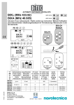
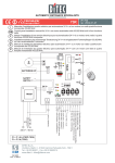
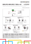
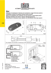
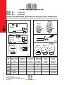
BIX L..
BIX A..
433.92 MHz
40.685 MHz
Istruzioni d’uso radiocomando / Radio control use instruction / Manuel d’utilisation pour
telecommande / Bedienungshandbuch für Fernsteuerung / Manual para el uso del telemando
BIXLG4
BIXAG4
PRG
SIG
BIXLP2
BIXLS2
L1
CH1
J1
BIXLR1
CH2
ANT
CH1
CH2
CH3
PRG
(only for BIXLP2)
PRG
CH4
OUT1
fig. 2
BixMR2
COM
L2
L1
PRG SIG
J1
J2
OUT2
BIXLR2
BIXAR2
S1
ANT
fig. 3
OUT1
BIXLG4
BIXAG4
N.O. 24 V=
N.C. 12 V=
J1
J2
BIXLS2
CH1
CH2
CH3
CH4
BIXLP2
ON
PRG
1 2 3 4 5 6 7 8 910
+
12V
-
+
12V
-
PRG
+
12V
-
fig. 1
I
GB
F
D
E
Alimentazione Assorbimento
N° canali
N° codici mem
Power supply
Absorption
N° channels N° memo code
Alimentation
Absorption
N° canaux N° codes mém
Zuführ
Stromaufnahme N° Känale
N° Codes
Alimentaciòn Absorbimiento N° canales
N° codigos
BIXLR1
IP1575 28-02-2003
fig. 4
24 V=
BIXLR2
12÷24 V=
BIXAR2
BIXLP2 12 V= 33mAh
(MN21)
BIXLS2
BIXLG4 12 V= 33mAh
(MN21)
BIXAG4
Uscita
Output
Sortie
Aufgang
Salida
Portata
Range
Portée
Reichtweite
Alcance
12 mA
1
200
1 (transistor)
/
12 mA
2
200
2 (relay 1A 30V)
/
/
2
/
/
50÷100 m
/
4
/
/
50÷100 m
70÷150 m
DITEC S.p.A.
Via Mons. Banfi, 3
21042 Caronno P.lla (VA) Italy
Tel.+39 02 963911 - Fax +39 02 9650314
www.ditec.it
ISO 9001 - Cert. n° 0957/1
2s
CH2
CH1
PRG
PRG
1
1
TX già memorizzato
Stored TX (NO BIXLS2)
DICHIARAZIONE CE DI CONFORMITÀ
Fabbricante: DITEC S.p.A. - via Mons. Banfi, 3 - 21042 Caronno
Pertusella (VA) – ITALY.
Dichiara che i radiocomandi BIXLR1, BIXLR2, BIXLS2, BIXLP2 e
BIXLG4 (433.92 MHz) e BIXAR2 e BIXAG4 (40.685 MHz) sono
conformi alle condizioni delle seguenti direttive CE: Direttiva R&TTE
1999/5/CE, Direttiva EMC 89/336/CEE e Direttiva bassa tensione
73/23/CEE.
Caronno Pertusella, 31-08-2000.
Fermo Bressanini
(Presidente)
1. Trasmettitore
I radiocomandi serie BIX sono preposti per l’attivazione di automatismi per vani passaggio e rispondono ai requisiti essenziali stabiliti
dalla direttiva 1999/5/CE R&TTE.
Il trasmettitore è dotato di un codice individuale (Rolling Code) che
lo distingue da qualsiasi altro trasmettitore.
Nuovo TX
New TX
CH2
CH1
2
3
Attendere10 s
Wait for 10 s
Fig. 5
PAESI CHE HANNO RECEPITO LA DIRETTIVA
R&TTE 1999/5/CE
COUNTRIES WHICH HAVE ADMITTED THE R&TTE
DIRECTIVE, 1999/5/C, INTO THEIR LEGISLATION.
STATUS
COUNTRY
NO LICENCE REQUIRED
AUSTRIA
NO LICENCE REQUIRED
BELGIUM
NO LICENCE REQUIRED
DENMARK
NO LICENCE REQUIRED
ESTONIA
NO LICENCE REQUIRED
FINLAND
NO LICENCE REQUIRED
FRANCE
NO LICENCE REQUIRED
GERMANY
NO LICENCE REQUIRED
GREECE
NO LICENCE REQUIRED
HUNGARY
NO LICENCE REQUIRED
ICELAND
NO LICENCE REQUIRED
IRELAND
NO LICENCE REQUIRED
ITALY
NO LICENCE REQUIRED
LICHTENSTEIN
NO LICENCE REQUIRED
LUXEMBOURG
NO LICENCE REQUIRED
NETHERLANDS
NO LICENCE REQUIRED
NORWAY
NO LICENCE REQUIRED
PORTUGAL
NO LICENCE REQUIRED
SPAIN
NO LICENCE REQUIRED
SWEDEN
NO LICENCE REQUIRED
SWITZERLAND
NO LICENCE REQUIRED
UNITED KINGDOM
2. Ricevitore
I ricevitori sono previsti per essere inseriti direttamente nei quadri
elettrici DITEC. Solo i BIXLR2 e BIXAR2 possono essere usati con
la base porta scheda CONT1. Il ricevitore può ricevere i codici di
tutti i trasmettitori, ma attiverà l’uscita di comando solo se il codice
ricevuto é presente nella lista dei codici abilitati (max. 200 codici).
Verificare che la memoria BixMR2 sia inserita sul connettore COM
del ricevitore BIXLR2/AR2.
Attenzione: l’inserimento e l’estrazione del BixMR2 devono essere effettuati in assenza di alimentazione.
I ricevitori BIXLR1 e BIXLR2 sono dotati di antenna (filo rigido L=
173 mm). In alternativa è possibile collegare l’antenna accordata
BIXLA. I ricevitori BIXAR2 devono essere collegati all’antenna
accordata BIXAA. Per collegare l’antenna al ricevitore usare cavo
coassiale RG58 (max. 10 m).
L’antenna va posizionata il più in alto possibile, lontano da strutture
metalliche (nel lampeggiante LAMP e LAMPH è previsto un morsetto
per il collegamento dell’antenna).
3. ABILITAZIONE TRASMETTITORI (Fig. 5)
3.1 Premere il pulsante PRG sul ricevitore (alimentato), il led segnalazione SIG si accende, oppure premere PRG di un
trasmettitore già memorizzato (BixLP2, BixLG4 o BixAG4)
per almento 2 s (entro la portata del ricevitore alimentato),
facendo attenzione a non memorizzare i nuovi trasmettitori
su impianti presenti nelle vicinanze.
3.2 Solo con BIXLS2. Selezionare mediante i 10 dip-switch il
codice di codifica desiderato, tra i 1024 possibili.
3.3 Effettuare una trasmissione premendo uno qualsiasi dei pulsanti
CH del nuovo trasmettitore. Il trasmettitore viene così abilitato. Durante questa fase il led segnalazione SIG lampeggia. Quando il
led torna acceso fisso è possibile abilitare un nuovo trasmettitore.
Abilitare tutti i nuovi trasmettitori effettuando una trasmissione come indicato sopra.
N.B.: (Solo con BIXLS2) E’ sufficiente memorizzare un solo
TX. Tutti i TX aventi lo stesso codice sono abilitati.
3.4 L’uscita dalla procedura avviene in modo automatico dopo 10 s
dall’ultima trasmissione oppure premendo nuovamente il tasto
PRG (il led SIG si spegne).
Tutti i diritti sono riservati
I dati riportati sono stati redatti e controllati con la massima cura. Tuttavia non possiamo assumerci alcuna responsabilità per eventuali errori,
omissioni o approssimazioni dovute ad esigenze tecniche o grafiche.
All right reserved
All data and specifications have been drawn up and checked with the
greatest care. The manufacturer cannot however take any responsibility
for eventual errors, ommisions or incomplete data due to technical or
illustrative purposes.
Touts droits reservés
Les informations mentionnées dans ce catalogue ont été controlées
avec la plus grande attention. Toutefois, nous déclinos toute
responsabilité en cas d’erreurs, omissions ou approximations dépendant
d’exigences techniques ou graphiques.
Alle Rechte vorbehalten
Die wiedergegebenen Daten wurden mit höchster Sorgfalt
zusammengestellt und überprüft. Es kann jedoch keinerlei
Verantwortung für eventuelle Fehler, Auslassungen oder Näherungen,
die technischen oder graphischen Notwendigkeiten zuzuschreiben sind,
übernommen werden.
Todos los derechos son reservados
Los datos que se indican han sido redactados y controlados con la
màxima atenciòn. Sin embargo no podemos asumir ninguna
responsabilidad por eventuales errores, omisiones o aproximaciones
debidas a exigencias técnicas o gràficas.
DITEC S.P.A. - IP1575 - BIX L / A
4. SELEZIONE CANALI
Per attivare l’uscita 1 (OUT1) del ricevitore selezionare con il
ponticello J1 il canale desiderato. Per attivare l’uscita 2 (OUT2) del
ricevitore selezionare con il ponticello J2 il canale desiderato. Canali preimpostati: CH1 attiva OUT1, CH2 attiva OUT2. I led L1 e
L2 indicano rispettivamente l’attivazione dell’uscita 1 e 2.
5. Disabilitazione di tutti i trasmettitori
- Tenere premuto il pulsante PRG sul ricevitore, finché il led SIG
comincia a lampeggiare.
- Premere nuovamente il pulsante PRG entro 6 s per confermare l’operazione. La conferma viene segnalata da un lampeggio
del led SIG a frequenza più elevata.
2
ITALIANO
AVVERTENZE GENERALI PER LA SICUREZZA
Le presenti avvertenze sono parte integrante ed essenziale del prodotto e devono essere consegnate all’utilizzatore.
Tenere fuori dalla portata dei bambini i radiocomandi, per evitare che la porta
o cancello motorizzati possa essere azionata involontariamente.
Non usare il radiocomando senza avere la completa visuale della porta o
cancello motorizzati.
I materiali dell’imballaggio (plastica, polistirolo, ecc.) e le batterie non vanno
dispersi nell’ambiente e non devono essere lasciati alla portata dei bambini in
quanto potenziali fonti di pericolo.
CONSIGNES GENERALES DE SECURITE
Ces consignes sont partie intégrante et essentielle du produit
et doivent être remises à l’utilisateur.
Garder hors le portée des enfants les radiocommandes afin d’éviter
que la porte ao le portail automatisés puissent être actionnés involontairement. N’utilisez pas la radiocommande si vous ne voyez pas
entierement la porte au portail motorisés.
Les materiaux de l’emballage (plastique, polystyréne, etc ne doivent
pas être abandonnés dand la nature et ne doivent pas être laissés à
la portée des enfants, car ils sont une source potentielle de danger.
EC DECLARATION OF CONFORMITY
Manufacturer: DITEC S.p.A. - via Mons. Banfi, 3 - 21042 Caronno
Pertusella (VA) – ITALY.
Herewith declares that the radio controls BIXLR1, BIXLR2, BIXLS2,
BIXLP2 e BIXLG4 (433.92 MHz) and BIXAR2 and BIXAG4 (40.685
MHz) are in conformity with the provisions of the following EC directives: R&TTE Directive 1999/5/EC, EMC Directive 89/336/EEC and
Low Voltage Directive 73/23/EEC.
Caronno Pertusella, 31-08-2000.
Fermo Bressanini
(Chairman)
DECLARATION CE DE CONFORMITE
Fabricant: DITEC S.p.A. - via Mons. Banfi, 3 - 21042 Caronno
Pertusella (VA) – ITALY.
Déclare ci-après que les radiocommandes BIXLR1, BIXLR2, BIXLS2,
BIXLP2 e BIXLG4 (433.92 MHz) et BIXAR2 et BIXAG4 (40.685
MHz) sont conforme aux dispositions des directives CEE suivantes:
Directive R&TTE 1999/5/CE, Directive EMC 89/336/CEE et Directive basse tension 73/23/CEE.
Caronno Pertusella, 31-08-2000.
Fermo Bressanini
(Président)
1. Transmitter
The BIX series of remote controls are designed for the activation of
1. Émetteur
Les télécommandes radio de la série BIX permettent d’activer des
automatismes pour les ouvertures de passage et répondent aux
exigences essentielles de la directive 1999/5/CE R&TTE.
L’émetteur est doté d’un code individuel (Rolling Code) qui le distingue de tout autre émetteur.
automatic accesses and are built in compliance with the R&TTE
Directive, 1999/5/C.
The transmitter is provided with its own code (Rolling code) different from that of any other transmitter.
2. Receiver
Receivers are designed for directly inserting into DITEC electrical
boards. Only the BIXLR2 and BIXAR2 version can be used with
CONT1 card holders. The receiver can receive the codes from all
transmitters but will only respond upon receiving a code which is
included in its file of authorised codes (max. 200 codes).
Check that memory BixMR2 is inserted on COM connector of
receiver BIXLR2/AR2.
Attention: Insertion and removal of the BIXMR module must
be made with the unit powered off.
The receivers BIXLR1 and BIXLR2 are equipped with a 173 mm
long rigid antenna. Alternatively, it may be linked up to a BIXLA. The
BIXAR2 receivers must be linked up to the BIXAA tuned antenna.
Tuned antenna by means of an RG58 coaxial cable with a maximum length of 10 metres.
The antenna must be mounted as high up as possible, away from
any metal structures (the LAMP and LAMPH flashing lights are
provided with a clamp for linking up of the antenna).
3.
3.1
3.2
3.3
3.4
2. Récepteurs
Les récepteurs sont conçus pour être mis en place directement dans
les tableaux de commande DITEC. Seul les BIXLR2 et BIXAR2 peut
être utilisé avec les bases porte cartes CONT1. Le récepteur peut
recevoir les codes de tous les émetteurs, mais il n’activera la sortie de
commande que si le code reçu est présent dans la liste des codes
autorisés (max. 200 codes).
Vérifier si la mémoire BixMR2 est introduite sur le connecteur
COM du récepteur BIXLR2/AR2.
Attention: l’enfichage et l’extraction du module mémoire BIXMR
doivent s’effectuer sans alimentation.
Les récepteurs BIXLR1 et BIXLR2 sont doté d’une antenne (fil rigide
L = 173 mm). En alternative, il est possible de relier l’antenne accordée BIXLA. Les récepteurs BIXAR2 doivent être reliés à l’antenne
accordée BIXAA. Pour relier l’antenne au récepteur, utiliser un câble
coaxial RG58 (max. 10 m).
L’antenne doit être installée le plus haut possible, loin de structures
métalliques (les clignotants LAMP et LAMPH sont dotés d’une borne
pour le branchement de l’antenne).
ENABLING THE TRANSMITTERS
Press the PRG button on the receiver (powered). The SIG
warning LED lights up, or press the PRG of a previously
stored transmitter (BixLP2, BixLG4 or BixAG4) for at least 2
s (within the range of the powered receiver) paying attention not to store the new transmitters in nearby systems.
Only with BIXLS2. Select the desired code among the 1024
possible ones by means of the 10 dip-switches.
Carry out a transmission by pressing any of the CH buttons
of the new transmitter.
During this operation the SIG LED will be flashing.
A new transmitter can be enabled once the SIG LED has
stopped flashing and become fixed.
Enable all the transmitters by transmitting a signal as above
mentioned.
Note: (only with BIXLS2) Only one TX needs be memorized.
All TXs having the same code are enabled.
Exiting from the transmitter enabling function will occur automatically 10 seconds after last transmission or by pressing
PRG again (the SIG LED will then go off).
3. ACTIVATION ÉMETTEURS
3.1 Appuyer sur le bouton PRG du récepteur (sous tension), la
led de signalisation SIG s’allume ou bien appuyer sur PRG
d’un transmetteur déjà mémorisé (BixLP2, BixLG4 ou BixAG4)
pendant au moins 2 sec. (dans la portée du récepteur sous
tension), en veillant à ne pas mémoriser les transmetteurs
nouveaux sur des installations présentes à proximité.
3.2 Uniquement avec BIXLS2. A l’aide des commutateurs DIP 10,
sélectionner le code désiré parmi les 1024 codes possibles.
3.3 Effectuer une transmission en appuyant sur l’un quelconque
des boutons CH du nouvel émetteur. L’émetteur est activé.
Pendant cette phase, le voyant de signalisation SIG clignote. Quand le voyant redevient fixe, il est possible d’activer le nouvel émetteur. Activer tous les émetteurs en effectuant une transmission comme dit plus haut.
N.B.: (Uniquement avec BIXLS2) Il suffit de mémoriser un seul
émetteur. Tous les émetteurs ayant le même code sont activés.
3.4 Le système quitte de toute façon la procédure de façon
automatique 10 s après la dernière transmission ou en appuyant de nouveau sur le button PRG (le voyant SIG s’éteint).
4. SELECTING THE CHANNEL
Output 1 (OUT1) on the receiver is activated by the selected channel via the jumper on J1 of the receiver. Output 2 (OUT2)) on the
receiver is activated by the selected channel via the jumper on J2
of the receiver. Default channels: CH1 actives OUT1, CH2 actives OUT2. LEDs L1 and L2 signal that output 1 and 2, respectively, have been activated.
5.
-
4. SÉLECTION CANAUX
La sortie 1 (OUT1) du récepteur est activée par le canal sélectionné
par une barrette sur J1. La sortie 2 (OUT2) du récepteur est activée
par le canal sélectionné par une barrette sur J2. Canaux préposée:
CH1 activé OUT1, CH2 activé OUT2. Les voyants L1 et L2 indiquent
respectivement l’activation de la sortie 1 et 2.
5. Désactivation de tous les émetteurs
Maintenir enfoncé le bouton PRG sur le récepteur, jusqu’à ce
que le voyant SIG commence à clignoter.
Appuyer de nouveau sur le bouton PRG dans les 6 s suivantes
pour confirmer l’opération. La confirmation est signalée par un
clignotement du voyant SIG à une fréquence plus élevée.
Disabling all transmitters
Keep the PRG button on the receiver until the SIG LED starts flashing.
Within 6 seconds press the PRG button again to confirm the
operation. Confirmation will be signalled by the SIG LED flashing at a faster rate.
3
DITEC S.P.A. - IP1575 - BIX L / A
FRANÇAIS
ENGLISH
GENERAL SAFETY PRECAUTIONS
The following precautions are an integral and essential part of
the product and must be supplied to the user.
Keep remote control out of the reach of children, in order to avoid
possible involuntary activation of the motorised door or gate.
Do not use remote control out of the visual of the door and gate.
Packaging materials (plastic, polystyrene, etc.) and batteries must not
be allowed to litter the environment and must be kept out of the reach
of children for whom they may be a source of danger.
ADVERTENCIAS GENERALES DE SEGURIDAD
Las siguientes advertencias forman parte integrante y esencial del producto y deben ser entregadas al usuario.
Conservar fuera del alccance de los niños el telemando para evitar el
accionamiento accidental. No utilizar el radiomando si no se tiene
una visiòn completa de la puerta o de los portal motorizadas.
El material de embalaje (plàstico, poliestirol, etc.) debe desecharse
sin causar daño al medio ambiente y mantenerse fuera del alcance
de los niños, porque es una potencial fuente de peligro.
EG-KONFORMITÄTSERKLÄRUNG
Hersteller: DITEC S.p.A. - via Mons. Banfi, 3 - 21042 Caronno Pertusella (VA) – ITALY.
erklärt hiermit, daß die Fernsteuerungen BIXLR1, BIXLR2, BIXLS2,
BIXLP2 e BIXLG4 (433.92 MHz) und BIXAR2 und BIXAG4 (40.685
MHz) mit den einschlägigen Bestimmungen folgender EG-Rchtlinien
übereinstimmen: R&TTE-Richtlinie 1999/5/EWG, EMC-Richtlinie 89/
336/EWG und Niederspannungsrichtlinie 73/23/EWG.
Caronno Pertusella, 31-08-2000.
Fermo Bressanini
(Präsident)
DECLARACIÓN CE DE CONFORMIDAD
Fabricante: DITEC S.p.A. - via Mons. Banfi, 3 - 21042 Caronno
Pertusella (VA) – ITALY.
Declara que los radiomando BIXLR1, BIXLR2, BIXLS2, BIXLP2 e
BIXLG4 (433.92 MHz) y BIXAR2 y BIXAG4 (40.685 MHz) son conformes con las condiciones de las siguientes directivas CE: Directiva
R&TTE 1999/5/CE, Directiva EMC 89/336/CEE y Directiva baja tensión 73/23/CEE.
Caronno Pertusella, 31.08.2000.
Fermo Bressanini
(Presidente)
1. Sender
Die Fernsteuerungen der Typenreihe BIX dienen der Aktivierung
von Tür- und Torantrieben und entsprechen den wesentlichen Anforderungen der Richtlinie 1999/5/CE R&TTE.
Der Sender verfügt über einen individuellen Code (Rolling Code),
der ihn von allen anderen unterscheidet.
1. Transmisor
Los radiomandos de serie BIX se utilizan para la activación de
aparatos automatizados previstos para áreas de paso y están conformes con los requisitos básicos establecidos por la directiva 1999/5/
CE R&TTE.El transmisor posee un código individual (Rolling Code)
que lo distingue de cualquier otro transmisor.
2. Empfänger
Die Empfänger sind für den direkten Einbau in die DITEC-Steuerungen vorgesehen. Nur die BIXLR2 und BIXAR2 können mit den
Basisports der Platinen CONT1 verwendet werden. Der Empfänger
kann die Codes aller Sender empfangen, aber aktiviert den Steuerausgang nur, wenn der empfangene Code in der Liste der aktivierten
Codes (max. 200) enthalten ist.
Prüfen, dass der Speicher BixMR2 an den COM-Anschluss des
Empfängers BIXLR/AR2 angeschlossen ist.
Achtung: Beim Einsetzen und Herausnehmen des Speichermoduls
BIXMR darf kein Strom zugeführt werden.
Die Empfänger BIXLR1 und BIXLR2 verfügen über eine Antenne
(starrer Draht L = 173 mm). Als Alternative kann die abgestimmte
Antenne BIXLA angeschlossen werden. Die Empfänger BIXAR2
müssen mit der abgestimmten Antenne BIXAA verbunden werden.
Zum Anschluß der Antenne ein Koaxialkabel RG58 (max. 10 m)
verwenden.
Die Antenne muß so hoch als möglich und weit von Metallkonstruktionen entfernt installiert werden (im Blinklicht LAMP und
LAMPH ist eine Anschlußklemme für die Antenne vorgesehen).
2. Receptor
Los receptores están pensados para ser introducidos directamente en
los cuadros eléctricos DITEC. Solamente BIXLR2 y BIXAR2 pueden
ser usados con las bases porta-fichas CONT1. El receptor puede
recibir los códigos de todos los transmisores, pero activará la salida de
mando solamente si el código recibido está presente en la lista de los
códigos habilitados (máx. 200 códigos).
Verificar que la memoria BixMR2 esté insertada en el conector
COM del receptor BIXLR2/AR2.
Atención: la inserción y extracción del módulo memoria BIXMR
deben ser efectuadas sin alimentación.
Los receptores BIXLR1 y BIXLR2 posee una antena (alambre rígido
L= 173 mm). Como alternativa es posible conectar la antena facilitada BIXLA. Los receptores BIXAR2 deben ser conectados a la antena sintonizada BIXAA. Para conectar la antena al receptor usar un
cable coaxial RG58 (máx.10 m).
La antena ha de ser colocada lo más alto posible, lejos de estructuras metálicas ( en el indicador LAMP y LAMPH tenemos un borne
para la conexión de la antena).
3.
3.1
3.2
3.3
3.4
3.
HABILITACIÓN DE LOS TRANSMISORES
3.1 Presionar el pulsador PRG en el receptor (bajo tensión), el led
de señalización SIG se enciende o bien presionar PRG de un
transmisor memorizado (BixLP2, BixLG4 o BixAG4) por lo menos
durante 2 s (dentro del alcance del receptor bajo tensión),
asegurándose de no memorizar los nuevos transmisores en
los equipos que se encuentran en las cercanías.
3.2 Sólo con BIXLS2. Seleccionar mediante los 10 conmutadores
DIP el código de codificación deseado entre los 1024 posibles.
3.3 Efectuar una transmisión presionando un pulsador cualquiera CH del nuevo transmisor. Llevar a cabo una transmisión
pulsando uno de los botones de canal del transmisor. De
esta manera se habilita el transmisor. Durante esta fase el
led señalización SIG relampaguea. Cuando el led se enciende de nuevo de forma fija es posible habilitar un nuevo
transmisor. Habilitar todos los transmisores efectuando una
transmisión como dicho mas arriba.
N.B.: (Sólo con BIXLS2) Basta con memorizar un solo TX.
Todos los TX que poseen los mismos códigos están habilitados.
3.4 La salida de este procedimiento se realiza automática después de 10 segundos desde la última transmisión o bien presionando nuevamente el pulsador PRG (el led SIG se apaga).
AKTIVIERUNG DER SENDER
PRG-Taste am (mit Strom versorgten) Empfänger drücken,
die LED-Anzeige SIG leuchtet auf oder mindestens 2 Sekunden lang die PRG-Taste eines bereits programmierten
Senders (BixLP2, BixLG4 oder BixAG4) drücken (innerhalb
der Reichweite des mit Strom versorgten Empfängers),
wobei darauf zu achten ist, dass die neuen Sender nicht
auf Anlagen programmiert werden, die sich in der Nähe
befinden.
Nur bei BIXLS2. Über die 10 Dip-Schalter die gewünschte
Codierung aus den 1024 möglichen Codes auswählen.
Führen Sie eine Übertragung durch, indem Sie eine beliebige
Taste CH des neuen Senders drücken. Durch Betätigen einer
jeder der Kanaltasten des Senders, ein Signal senden. Auf
diese Weise wird er aktiviert. Während dieser Phase blinkt
die Led SIG. Sobald sie wieder konstant leuchtet, kann ein
neuer Sender aktiviert werden. Alle Sender nach der gleichen Vorgehensweise aktivieren wie obengennant.
Hinweis: (nur bei BIXLS2) Es reicht aus, nur ein TX zu speichern,
denn dann werden alle TX mit dem gleichen Code aktiviert.
Das Verfahren wird 10 s nach der letzten Sendung automatisch verlassen oder durch erneutes Drücken der Taste PRG
(die Led SIG löscht ab).
4. SELECCIÓN DE LOS CANALES
La salida 1(OUT1) del receptor se activa a través del canal seleccionado mediante un conector puente en J1. La salida 2 (OUT2) del
receptor se activa a través del canal seleccionado mediante un conector
puente en J2. Canales preseleccionados: CH1 activa OUT1, CH2
activa OUT2. Los led L1 y L2 indican respectivamente la activación
de la salida 1 y 2.
4. KANALANWAHL
Der Ausgang 1 (OUT1) wird vom angewählten Kanal mittels Brücke
auf J1 aktiviert. Der Ausgang 2 (OUT2) wird vom angewählten Kanal
mittels Brücke auf J2 aktiviert. Vorangelegte Känale: CH1 aktiviert
OUT1, CH2 aktiviert OUT2. Die Led L1 und L2 zeigen die Aktivierung
jeweils der Ausgänge 1 und 2 an.
5. Deshabilitación de todos los transmisores
Mantener pulsado el botón PRG en el receptor hasta que el led
SIG empiece a relampaguear.
Pulsar nuevamente el botón PRG antes de que pasen 6 segundos
para confirmar la operación. La confirmación se señala con un
destello del led SIG con una frecuencia más elevada.
5. Deaktivierung aller Sender
Die Taste PRG ca. 2s drücken, bis die Led SIG zu blinken beginnt.
Die Taste PRG innerhalb von 6s zur Bestätigung nochmals
drücken. Die Bestätigung wird von der Led SIG durch schnelleres Blinken angezeigt.
DITEC S.P.A. - IP1575 - BIX L / A
4
ESPAÑOL
DEUTSCH
ALLGEMEINE SICHERHEITSHINWEISE
Diese Hinweise sind als wesentlicher Bestandteil des Produktes dem Benutzer auszuhändigen.
Funk-Fernsteuerungen von Kindern fernhalten, damit der Torantrieb
nicht unbeabsichtig ausgelöst werden kann. Die Fernsteuerung nicht
verwenden ob das Tor und das Gittertor nicht sehen.
Das Verpackunsmaterial (Kunststoff, Polystyrol, usw. ) ist vorschriftsmäßig zu entsorgen. Es ist von Kindern fernzuhalten, da es eine Gefahr
für sie bedeutet.