1
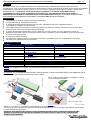
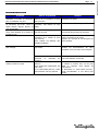
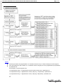
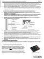
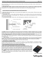
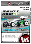
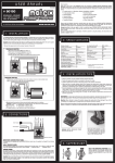
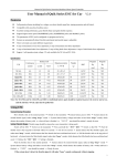
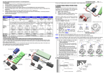
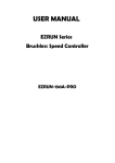
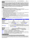
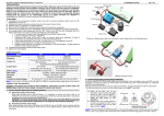
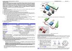
Brushless Speed Controller
80-150A 1/8th series
and all others Xtronics programmable ESC
1/18, 1/10, Short Course, Monster truck....
FRANCAIS ENGLISH
USER MANUAL
MANUEL D'UTILISATION
ATTENTION !
Toutes modifications du produit, entrainera une annulation immédiate
de toutes prise en charge de notre service après vente.
Pour toutes question technique portant sur l'utilisation de ce produit,
veuillez vous réferer à cette notice d'utilisation, à votre revendeur ou
par email :
[email protected]
Brushless Speed Controller
Page
-3-
FRANCAIS
Instruction d'utilisation du controleur Xtronics-80A et Xtronics-150A 1/8ème
Déclaration
Merci pour l'achat de ce contrôleur Brushless. Ces contrôleurs haut de gamme spécifiques à la RC peuvent être
très dangereux, nous vous recommandons de lire attentivement la notice. Hobbytech ne possède aucun contrôle sur l'utilisation,
l'installation ou la maintenance de ses produits et ne couvre pas en garantie les dommages, les pertes et la mauvaise
utilisation de celui-ci.ATTENTION, TOUTE MODIFICATION DU PRODUIT (ex: SOUDURE, CHANGEMENT DE FILS,
CHANGEMENT DU VENTILATEUR, CHANGEMENT DE CONNECTEUR), ENTRAINERA UNE ANNULATION FERME ET
IMMEDIATE DE TOUTE PRISE EN CHARGE DE NOTRE SERVICE APRES-VENTE. Attention, le contrôleur 80 Amp. n'accepte
pas l'alimentation par une batterie Lipo 5S (18,5V) ou une batterie NiMh de plus de 12 éléments.
Caractéristiques
Compatible avec tous les moteurs brushless ou sensorless
Excellent démarrage, accélération et linéarité
3 modes de fonctionnement (marche avant avec frein, avant/arrière avec frein, avant/arrière direct)
4 possibilités de réglages de marche arrière
Frein ABS proportionnel possédant 4 niveau de puissance de freinage maximum, 8 niveaux de frein moteur (dragbrake force) et 4 niveaux de freinage classique (à l'arrêt)
9 modes de démarrage (appelé aussi “Punch”) allant de “very soft” (niveau 1) à “very aggressive” (niveau 9)
Différentes protections: coupure de protection basse tension, protection contre la surchauffe, contre les pertes radio
et contre les blocages moteur
8 niveaux de réglage du timing
Programmation rapide et facile avec seulement un bouton et compatible avec un LCD program box (en option)
Ne craint ni les éclaboussures ni la poussière
Spécifications techniques
Modèle
Courant continu
Résistance
Type de voiture
Type de moteur brushless
Xtronics- 80A
80A/270A
0.0018 ohm
Piste et TT 1/8 / Trucks pour utilisation
classique ou RTR
8T (Note 1)
Xtronics- 150A
150A/1080A
0.0002 ohm
Piste et TT 1/8 / Trucks pour la compétition
3.5T (Note 1)
6-18 cellules (NiMH or NiCd)
6-12 cellules (NiMH or NiCd)
2-4 cellules Li-Po
2-6 cellules Li-Po
Sortie BEC
5.75V/3A (platine BEC intégrée) (Note 2)
Type de moteur
Moteur brushless sensorless ou sensored ou moteur à charbons
Dimensions
68(L)×55(W)×45(H)
Poids
150g (sans câbles)
Note 1: La valeur du “T” est testée dans le cadre de l'utilisation de 4 cellules Li-Po.
Note 2: Les ventilateurs et le moteur sont alimentés par le BEC et fonctionnent sous 5,75V.
Batterie
Première utilisation du contrôleur
ATTENTION ! CE SYSTEME BRUSHLESS EST TRES PUISSANT ! POUR VOTRE SÉCURITÉ, N'ALLUMEZ PAS POUR
LA PREMIÈRE FOIS VOTRE CONTROLEUR SUR LA PISTE.
1.
contrôleur,
le moteur,
le récepteur,
S'ilConnectez
y a deuxlepacks
d'accus
connectés
en série,
l'accu
et
le
servo
selon
le
schéma
ci-dessous
merci d'utiliser ce schéma:
Note3: Une petite prise femelle sort du BEC, elle est
utilisée pour connecter le ventilateur de refroidissement du moteur brushless.
Les fils A, B et C du contrôleur peuvent être branchés librement (pas de sens). Si le moteur tourne dans le sens contraire,
il suffit d'échanger les deux prises.
Remarque: Vous pouvez aussi inverser le sens de rotation de votre moteur en utilisant le réglage de votre
émetteur en inversant la voie des gaz en la mettant en position “reverse”. Dans ce cas, n'oubliez pasde
recalibrer votre contrôleur.
FRANCAIS
Instruction d'utilisation du controleur Xtronics-80A et Xtronics-150A 1/8ème
Page
-4-
2. Calibrage du contrôleur (calibrage des courses de gaz)
Le calibrage des courses de gaz s'effectue lors de la première utilisation du contrôleur, d'un nouvel émetteur ou lors d'un
changement de réglages du neutre, paramètres ATV et EPA. Sinon, le contrôleur ne peut fonctionner correctement.
3 points essentiels sont à régler: le neutre, la marche avant et la marche arrière.
Les schémas suivants vous expliquerons comment effectuer le calibrage avec votre émetteur.
A)
Eteignez votre contrôleur, branchez votre
emetteur, réglez la direction et le gaz sur
“REV”, mettre à 100% “EPA/ATV”, et
désactiver la fonction ABS.
B) Maintenez enfoncé le bouton “SET” puis
allumez votre contrôleur, relâchez le bouton
“SET” aussitôt que la LED rouge commence
à clignoter. (Note 4)
Note4: Si le bouton “SET” n'est pas relâché lorsque la LED rouge commence à clignoter, le contrôleur entrera en
mode programme, dans ce cas, éteignez le contrôleur et recalibrez les courses de gaz en reprenant l'étape A.
C) 3 points de réglages sont à effectuer
comme le schéma de droite.
1) La position neutre
Mettre la gachette des gaz en position
neutre et appuyez sur le bouton “SET”, la
LED verte s'allumera une fois.
2) La marche avant maximum
Accélérez avec la gachette des gaz à fond
et appuyez sur le bouton “SET”, la LED
verte clignotera 2 fois.
3) La marche arrière minimum
Freinez à fond avec la gachette et appuyez
sur le bouton “SET”, la LED verte
clignotera 3 fois.
D) Le calibrage des courses de gaz est
effectué, le moteur peut être allumé après
3 secondes.
3. Vérifications des LED en fonctionnement normal
1) Normalement, si la commande des gaz est au neutre, les LED rouge et verte ne s'allument pas.
2) La LED rouge s'allume lorsque la voiture est en marche avant ou arrière et se met à clignoter rapidement durant le
freinage.
3) La LED verte s'allume lorsque la gâchette est en marche avant ou arrière maximum.
4. Vérifications des cellules Lipo en cas d'utilisation d'une batterie au Lithium.
Si vous utilisez une batterie Lipo, nous vous conseillons fortement de configurer les “cellules Lipo” programmable
manuellement afin d'éviter tout problème de sur-décharge. Reportez vous aux instructions en page 6.
En utilisation normale, quand le contrôleur est allumé, le moteur émet plusieurs “bip” pour indiquer le nombre de cellules
du pack d'accus. Par exemple, “Bip-Bip” signifie qu'il y a 2 Lipo, “Bip-Bip-Bip” 3 cellules, etc.
Alertes sonores
1. Signal de tension d'entrée anormale: le contrôleur vérifie la tension d'entrée lorsque vous l'allumez, si la tension est
anormale, un signal sonore sera émit: “Bip-Bip, Bip-Bip, Bip-Bip” (une seconde d'intervalle entre chaque “bip-bip”)
2. Signal d'accélération anormale: lorsque le contrôleur ne peut détecter le signal normal des gaz, un signal
sonore sera émit: “bip-, bip-, bip-” (2 secondes d'intervalles entre chaque “bip”).
Page
-5-
Résolution des problèmes
Problème
Source du problème
Solution
Après mise sous tension du
contrôleur, le moteur ne fonctionne
pas, le ventilateur non plus.
Après mise sous tension, le moteur
ne fonctionne pas mais emet un
signal d'alerte “bip-bip, bip-bip” (à
1sec d'intervalle).
Après mise sous tension, la LED
rouge reste allumée et le moteur ne
fonctionne pas.
Le moteur tourne en sens inverse.
Les connexions entre le pack
d'accus et le contrôleur ne sont
pas correctes.
La tension du pack d'accus est
anormale, trop élevée ou trop
faible.
Vérifiez les connexions d'alimentation.
Remplacez les prises.
Le signal de la commande des
gaz est anormal.
Branchez correctement le fil de
commande des gaz dans le récepteur.
1)Les branchements entre le
contrôleur et le moteur ne sont
pas corrects.
2)Le châssis est différent des
modèles habituels.
Solution #1: Inversez les fils du moteur
entre le contrôleur et le moteur.
Solution #2: Inversez la voie des gaz sur
votre emetteur.
Le moteur s'arrête subitement en
plein roulage.
Le signal de réception est perdu
(top radio).
Vérifiez votre emetteur et votre récepteur.
Vérifiez les branchements de vôtre
contrôleur sur la voie 2 de votre recepteur.
Le contrôleur a détecté la tension
minimale
ou
maximale
de
coupure.
1) Mauvaise charge du pack
d'accus.
2)Le rapport de transmission est
trop court
3) Le “Start Mode (Punch)”, mode
d'accélération, est trop agressif.
LED rouge allumée: basse tension
LED verte allumée: surchauffe
Lors d'une accélération rapide, le
moteur s'arrête ou coupe.
Vérifiez la tension de votre pack d'accus.
la
1) Remplacez votre pack d'accus.
2) Utilisez un moteur avec un KV plus
faible ou changez votre rapport de
transmission.
3) Descendre le “Start Mode (Punch)”,
mode d'accélération, à une valeur plus
souple.
FRANCAIS
Instruction d'utilisation du controleur Xtronics-80A et Xtronics-150A 1/8ème
FRANCAIS
Instruction d'utilisation du controleur Xtronics-80A et Xtronics-150A 1/8ème
Page
-6-
Programmer le contrôleur
1.
Méthode de programme
Note5:
Durant la procédure de programmation, le contrôleur émet des “bip” en même temps que la LED clignote.
Si le “N”est plus gros que le chiffre “5”, le contrôleur émet un long bip et un long clignotement qui représente
le paramètre n°5.
Par exemple, si la LED clignote ainsi:
“Un clignotement long + un clignotement court”(le moteur émet 2 bip) = paramètre n°6
“Un clignotement long + 2 clignotements courts”(1 bip long + 2 bips brefs) = paramètre n°7
“Un clignotement long + 3 clignotements courts (1 bip long 3 bips brefs) = paramètre n°8
……
Etc.
FRANCAIS
Instruction d'utilisation du controleur Xtronics-80A et Xtronics-150A 1/8ème
Page
-8-
pack d'accus très performant et de qualité avec une puissante capacité de charge, autrement ces modes ne
peuvent être réellement exploités. Si le moteur n'est pas linéaire (accoûts, coupures), c'est peut-être due à la faible
capacité de décharge du pack de batterie, pensez donc à le remplacer par un pack plus performant.
2.5.
Puissance du freinage (Maximum Brake Force) : Le contrôleur possède un système de freinage proportionnel.
La force de freinage est liée à la position de la gâchette des gaz. Plus la gâchette est poussée vers l'extérieur, plus
le frein sera puissant. Une très grande force de freinage peut réduire le temps de celui-ci, mais peut évidemment
endommager la transmission.
Les paramètres ci-dessous sont seulement accessibles avec le boitier de programmation
2.6.
Puissance de la marche arrière ( Maximum Reverse Force): Les différentes valeurs permettent de varier la
vitesse maximum en marche arrière.
2.7.
Frein moteur initial (Initial Brake Force): Appelé aussi “puissance de freinage minimale”, il s'agit de la puissance
du freinage lorsque la gâchette est dans la position initiale de la marche arrière. Par défaut, la valeur est
équivalente à la valeur du réglage du frein moteur, de sorte à optimiser le freinage.
2.8.
Sensibilité de la zone de neutre des gaz (Throttle Neutral Range): Référez vous aux schémas suivants pour
régler la sensibilité de la zone de neutre des gaz.
2.9.
Timing: Il existe de nombreuses différences entre les performances et les paramètres des différents moteurs
brushless, c'est pourquoi le timing du contrôleur n'est pas compatibles avec tous les moteurs. Il est donc
nécessaire d'avoir un timing programmable. Choisissez les valeurs du timing les plus appropriées à l'utilisation de
votre moteur. En général, plus les valeurs sont hautes, plus le système sera ralenti.
2.10. Protection thermique (Over-Heat Protection): Si la fonction est activée, l'alimentation sera coupée si la
température du contrôleur est plus élevée que la valeur préréglée en usine durant 5 secondes. Quand la protection
fonctionne, la LED verte clignote comme ceci: “☆-,☆-,☆-”.
2.11. Rotation du moteur (Motor Rotation): Vous pouvez utiliser cette fonction pour changer le sens de rotation. Face
à l'axe du moteur (l'arrière du moteur doit rester loin de votre visage), déplacez la manette des gaz à fond. Si ce
point est réglé sur “CW”, l'axe tourne dans le sens des aiguilles d'une montre.
2.12. Cellules Lipo (Lipo Cells): Nous vous conseillons fortement de configurer les cellules Lipo manuellement. (voir
paramètre 3)
3. Rétablissement des réglages par défaut
A tout moment, lorsque la gâchette est au neutre (excepté lors du calibrage ou de la programmation), appuyez sur “SET”
pendant 3 secondes, les LED rouge et verte clignoteront alors en même temps, cela signifiera que les programmes ont
été réinitialisés.
4. Programmation à l'aide du boitier (Ref: XT ESC.card)
Le boitier est un équipement optionnel vendu séparément. Il possède
une interface conviviale. La procédure de programmation du contrôleur
devient plus simple et rapide avec ce dispositif de poche. Quand les
valeurs doivent être modifiées, il suffit de brancher les fils du contrôleur
(trois fils, noir, rouge et blanc) dans le boitier (la prise se situe sur le
- +
) puis connectez la batterie principale
u a
côté, et marquée par
contrôleur. Après plusieurs secondes, les valeurs et programmes
s'afficheront sur le boitier. Utilisez les boutons “ITEM” et “VALUE” pour
sélectionner les éléments du programmes et leurs nouvelles valeurs,
puis appuyez sur “OK” pour valider les nouveaux réglages du contrôleur.
Ref: XT ESC.CARD
USER MANUAL
WARNING !
All modification of this product will automaticly
cancell the warranty
For all technical inquiry, please contact your local dealer
or contact our technical support by email :
[email protected]
Brushless Speed Controller
ENGLISH
User Manual of Xtronics-80A and Xtronics-150A 1/8 scale Brushless ESC
Page
-10 -
Declaration
Thanks for purchasing our Electronic Speed Controller (ESC). High power system for RC model can be very
dangerous, so we strongly suggest you read this manual carefully. In that we have no control over the
correct use, installation, application, or maintenance of our products, no liability shall be assumed nor
accepted for any damages, losses or costs resulting from the use of the product. Any claims arising from the
operating, failure of malfunctioning etc. will be denied. We assume no liability for personal injury,
consequential damages resulting from our product or our workmanship. As far as is legally permitted, the
obligation to compensation is limited to the invoice amount of the affected product.
Features
Compatible with all sensorless brushless motors
Excellent start-up, acceleration and linearity features.
3 running modes (Forward only with brake, Forward/Reverse with brake, Forward/Reverse immediately)
4 steps of maximum reverse force adjustment.
Proportional ABS brake function with 4 steps of maximum brake force adjustment, 8 steps of drag-brake force
adjustment and 4 steps of initial brake force adjustment.
9 start modes (Also called “Punch”) from “very soft (Level 1)” to “very aggressive (Level 9)”.
Multiple protection features: Low voltage cut-off protection / Over-heat protection / Throttle signal loss protection
/ Motor blocked protection.
8 steps of timing adjustment by software.
Built-in switch mode BEC has a powerful output to supply all the electronic equipments.
Easily program with only one button and compatible with pocket-sized Program Card.
Splash proof and dustproof.
Specifications
Model
Xtronics-80A
Xtronics-150A
80A/270A
150A/1080A
0.0018 ohm
0.0002 ohm
1/8 on-road and off-road cars / trucks
1/5, 1/8 on-road and off-road cars / trucks
Suitable Car
for general race or RTR application
for competitive race
≥8T (Note 1)
≥3.5T (Note 1)
Suitable Brushless Motor
6-12 cells Ni-xx (NiMH or NiCd)
6-18 cells Ni-xx (NiMH or NiCd)
Battery
2-4 cells Li-Po
2-6 cells Li-Po
5.75V/3A of switch mode built-in BEC (Note 2)
BEC Output
Sensorless brushless motor
Motor Type
68(L)×55(W)×45(H)
Dimension
150g(Without wires)
Weight
Note 1: The value of “T” number is tested under the input of 4 cells Lipo battery;
Note 2: The cooling fans of ESC and motor are supplied by the built-in BEC, so they are working under 5.75V.
Cont./Burst Current
Resistance
Begin To Use The New ESC
WARNING! THIS BRUSHLESS SYSTEM IS VERY POWERFUL! FOR SAFETY, PLEASE ALWAYS KEEP THE
WHEELS AWAY FROM THE TRACK WHEN YOU BEGIN TO SWITCH ON THE ESC.
1. Connect the ESC, motor, receiver, battery and servo according to the following diagram
If there are 2 battery packs need to be connected in
series, please refer to the following picture:
Note3: There is a small female connector that coming out from the “FAN” socket, this is used for connecting with the
cooling fan of the brushless motor.
User Manual of Xtronics-80A and Xtronics-150A 1/8 scale Brushless ESC
Page
-11-
The #A, #B, #C wires of the ESC can be connected with the motor wires freely (without any order). If the motor runs
in the opposite direction, please swap any two wire connections.
Note: You can also set the throttle channel of your transmitter to the “Reverse” direction, and then the
motor will run oppositely. Please calibrate the throttle range again after changing the direction of throttle
channel.
A) Switch off the ESC, turn on the
transmitter, set the direction of throttle
channel to ”REV”, set the “EPA/ATV”
value of throttle channel to “100%”, and
disable the ABS function of your
transmitter.
B) Hold the “SET” key and then switch on
the ESC, and release the “SET” key as
soon as possible when the red LED
begins to flash. (Note 4)
Note4: If you don’t release the “SET” key after the red LED begins to flash, the ESC will enter the program mode, in
such a case, please switch off the ESC and re-calibrate the throttle range again from step A.
C) Set the 3 points according to the
steps shown as the pictures on the
right side.
1) The neutral point
Move the throttle stick at the neutral
point, and then click the SET key, the
green LED flashes 1 time.
2) The end point of forward
direction
Move the throttle stick at the end
point of forward direction, and then
click the SET key, the green LED
flashes 2 times.
3) The end point of backward
direction
Move the throttle stick at the end
point of backward direction, and then
click the SET key, the green LED
flashes 3 times.
D) Throttle range is calibrated; motor
can be started after 3 seconds.
3. Check the LED Status in Normal Running
1) Normally, if the throttle stick is in the neutral range, neither the red LED nor the green LED lights.
2) The red LED lights when the car is running forward or backward and it will flash quickly when the car is braking.
3) The green LED lights when the throttle stick is moved to the top point (end point) of the forward zone or
backward zone.
4. Check the Lipo Cells Setting if You Are Using Lithium Battery
If you are using Lipo battery, we strong suggest setting the “Lipo Cells” programmable item manually to avoid the
over-discharge problem. Please read the instructions on page 6.
In normal case, when the ESC is switched on, the motor will emit several “Beep” tones to express the cells number of
the battery pack. For example, “Beep-Beep-” means 2s Lipo, “Beep-Beep-Beep-” means 3s Lipo, etc.
Alert Tones
1. Input voltage abnormal alert tone: The ESC begins to check the input voltage when power on, if the voltage is
ENGLISH
2. Throttle Range Setting (Throttle Range Calibration)
In order to make the ESC fit the throttle range, you must calibrate it when you begin to use a new ESC, or a new
transmitter, or change the settings of neutral position of the throttle stick, ATV or EPA parameters, etc. Otherwise the
ESC cannot work properly.
There are 3 points need to be set, they are the top point of “forward”,” backward” and the neutral point.
The following pictures show how to set the throttle range with a FutabaTM transmitter.
User Manual of Xtronics-80A and Xtronics-150A 1/8 scale Brushless ESC
2.
Page
-12-
out of the normal range, such an alert tone will be emitted: “beep-beep-, beep-beep-, beep-beep-” (There is 1
second interval between every “beep-beep-” tone).
Throttle signal abnormal alert tone: When the ESC can’t detect the normal throttle signal, such an alert tone will
be emitted: “beep-, beep-, beep-” (There is 2 seconds interval between every “beep-” tone).
Trouble Shooting
Possible Reason
The
connections
between
battery pack and ESC are not
correct
Input voltage is abnormal, too
high or too low
Solution
Check the power connections
Replace the connectors
Throttle signal is abnormal
Plug the control wire into the throttle
channel of the receiver correctly.
The motor runs in the opposite
direction when it is accelerated
1)The wire connections between
ESC and the motor are not
correct
2)The chassis is different from
the popular design
Method #1: Swap any two wire
connections between the ESC and the
motor
Method #2: Change the “Motor Rotation”
programmable item to “CW(Clockwise)”
The motor suddenly stops running
while in working state
The throttle signal is lost
Check the transmitter and the receiver
Check the signal wire from the throttle
channel of your receiver
Red LED flashes means Low Voltage
Green LED flashes means Over-heat
After power on, motor can’t work,
but emits “beep-beep-, beep-beep-”
alert tone. (Every “beep-beep-” has
a time interval of 1 second )
After power on, red LED always
lights, the motor doesn’t work
When accelerating quickly,
motor stops or trembles
the
The ESC has entered the Low
Voltage Protection Mode or
Over-heat Protection Mode
1) The battery has a bad
discharge performance
2) The gear rate is too small
3) The “Start Mode (Punch)” of
the ESC is too aggressive
Check the voltage of the battery pack
1) Use a better battery
2) Use lower KV motor or change the
gear rate
3) Set the “Start Mode (Punch)” to a
softer value
ENGLISH
Trouble
After power on, motor doesn’t work,
and the cooling fan doesn’t work
User Manual of Xtronics-80A and Xtronics-150A 1/8 scale Brushless ESC
Page
-13
-
Program The ESC
ENGLISH
1. Program Method
Note5:
In the program process, the motor will emit “Beep” tone at the same time when the LED is flashing.
If the “N” is bigger than the number “5”, we use a long time flash and long “Beep---” tone to represent “5”,
so it is easy to identify the items of the big number.
For example, if the LED flashes as the following:
“A long time flash + a short time flash” (Motor sounds “Beep---Beep”)
=
“A long time flash + 2 short time flash” (Motor sounds “Beep---BeepBeep”)
the No. 6 item
=
“A long time flash + 3 short time flash” (Motor sounds “Beep---BeepBeepBeep”)
……
And so on.
the No. 7 item
= the No. 8 item
User Manual of Xtronics-80A and Xtronics-150A 1/8 scale Brushless ESC
Programmable Items List
Page
-14-
9
(The italics texts in the above form are the default settings)
Table AA:
: Programmable
Items
for Xtronics-80A
Xtronics-150A
1/8th
Table
Programmable
Items
for S8A, S8Band
RTR
ESC
1. Running Mode
2.Drag Brake Force
1
2
3
4
Forward
with Brake
Forward/Reverse
with Brake
Forward and
Reverse
0%
5%
10%
20%
5
6
7
8
40%
60%
80%
100%
3.2V
/Cell
3.4V
/Cell
3.Low Voltage
Cut-Off Threshold
Non-Protection
2.6V/Cell
2.8V/Cell
3.0V
/Cell
4.Start Mode(Punch)
Level1
Level2
Level3
Level4
Level5
25%
50%
75%
100%
Disable
5.Max Brake Force
Table BB:: Programmable
Items
for For
all others
Xtronics programmable ESC
Table
Programmable
Items
S18,S16,S10A,S10B,S10C
RTR ESC
Programmable Value
Programmable
Items
1
2
3
4
1. Running Mode
2.Drag Brake Force
Forward
with Brake
Forward/Reverse
with Brake
0%
5%
5
6
7
8
30%
40%
10%
15%
20%
25%
2.6V/Cell
2.8V/Cell
3.0V
/Cell
3.2V
/Cell
3.4V
/Cell
Level1
Level2
Level3
Level4
25%
50%
75%
100%
3.Low Voltage
Cut-Off Threshold
Non-Protection
4.Start Mode(Punch)
5.Maximum Brake Force
Level6 Level7 Level8 Level9
2. Programmable Values
2.1. Running Mode: With “Forward Only with Brake” mode, the car can go forward and brake, but cannot go
backward, this mode is suitable for competition; “Forward/Reverse with Brake” mode provides backward function,
which is suitable for daily training.
Note: “Forward/Reverse with Brake” mode uses “Double-click” method to make the car go backward. When
you move the throttle stick from forward zone to backward zone for the first time (The 1st “click”), the ESC begins to
brake the motor, the motor speeds down but it is still running, not completely stopped, so the backward action is NOT
happened immediately. When the throttle stick is moved to the backward zone again (The 2nd “click”), if the motor
speed is slowed down to zero (i.e. stopped), the backward action will happen. The “Double-Click” method can
prevent mistakenly reversing action when the brake function is frequently used in steering.
By the way, in the process of braking or reversing, if the throttle stick is moved to forward zone, the motor will run
forward at once.
“Forward/Reverse” mode uses “Single-click” method to make the car go backward. When you move the
throttle stick from forward zone to backward zone, the car will go backward immediately. This mode is usually used
for the Rock Crawler.
2.2. Drag Brake Force: Set the amount of drag brake applied at neutral throttle to simulate the slight braking effect of
a neutral brushed motor while coasting.
2.3. Low Voltage Cut-Off: The function prevents the lithium battery pack from over discharging. The ESC detects the
battery’s voltage at any time, if the voltage is lower than the threshold for 2 seconds, the output power will be cut off,
There are 6 preset options for this item. You can customize the cutoff threshold by using a LCD program box
(optional equipment) to trim it with a step of 0.1V, so it will be more suitable for all kinds of batteries (NiMH, NiCd,
Li-ion, Lipo, LFP,etc). Please always keep in mind that the customized value is not for each cell, it is for the
WHOLE battery pack.
2.4. Start Mode (Also called “Punch”): Select from “Level1” to “Level9” as your like, Level1 has a very soft start
effect, while level9 has a very aggressive start effect. From Level1 to Level9, the start force is increasing. Please
note that if you choose “Level7” to “Level9” mode, you must use good quality battery pack with powerful discharge
ability, otherwise these modes cannot get the burst start effect as you want. If the motor cannot run smoothly (the
ENGLISH
Options
Programmable
Items
User Manual of Xtronics-80A and Xtronics-150A 1/8 scale Brushless ESC
Page
-15-
ENGLISH
motor is trembling), it may caused by the weak discharge ability of the battery pack, please choose a better battery or
increase the gear rate.
2.5. Maximum Brake Force: The ESC provides proportional brake function. The brake force is related to the position
of the throttle stick. Maximum brake force refers to the force when the throttle stick is located at the top point of the
backward zone. A very large brake force can shorten the brake time, but it may damage the gears.
The next values are not programmable without using Program Card
2.6. Maximum Reverse Force: Sets how much power will be applied in the reverse direction. Different value makes
different reverse speed.
2.7. Initial Brake Force: It is also called “minimum brake force”, and it refers to the force when the throttle stick is
located at the initial position of the backward zone. The default value is equal to the drag brake force, so the brake
effect can be very smoothly.
2.8. Throttle Neutral Range: Please refer to the following picture to adjust the neutral range as your like.
2.9. Timing: There are many differences among structures and parameters of different brushless motors, so a fixed
timing ESC is difficult to compatible with all brushless motors. It is necessary to make the timing value programmable.
Please select the most suitable timing value according to the motor you are just using. Generally, higher timing value
brings out higher power output, but the whole efficiency of the system will be slightly lower down.
2.10. Over-Heat Protection: If the function is activated, the output power will be cut-off when the temperature of the
ESC is higher than a factory-preset value for 5 seconds. When the protection happens, the Green LED will flash as
the following style: “☆-, ☆-, ☆-”.
2.11. Motor Rotation: You can use this item to change the rotation direction. Face to the motor shaft (That means
the rear cover of the motor is far from your face), and move the throttle stick to the top point of the forward zone. If
this item is set to “CCW”, the shaft runs counter-clockwise; If this item is set to “CW”, the shaft runs clockwise.
2.12. Lipo Cells: We strongly suggest setting the “Lipo Cells” item manually.
3. Reset All Items To Default Values
At any time when the throttle is located in neutral zone (except in the throttle calibration or parameters program
process), hold the “SET” key for over 3 seconds, the red LED and green LED will flash at the same time , which
means each programmable item has be reset to its default value.
4. Set The ESC By Using Program Card (Item: XT ESC.CARD)
Program card is an optional equipment which needs to be purchased separately. It has a
friendly user interface. The process of programming the ESC becomes quite easy and
fast with this pocket sized device. When the programmable value needs to be changed,
please just plug the control wires of the ESC (trio wires with black, red and white color)
into the socket of the program card (The socket is on the right corner, and marked
with - + ), and then connect the main battery pack to the ESC. After several seconds,
each item’s value will be shown on the program card. Use “ITEM” and “VALUE” buttons to
select the programmable items and new values, and then press “OK” button to store the
new settings into the ESC.
Item: XT ESC.CARD
Brushless Speed Controller