1
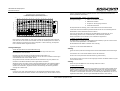
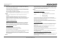
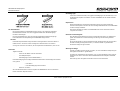
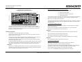
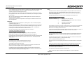
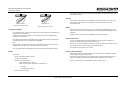
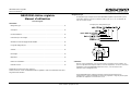
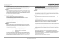
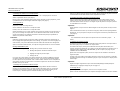
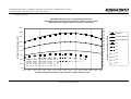
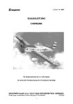
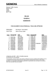
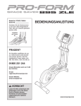
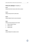
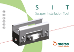
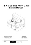
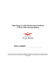
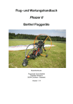
NEUFORM–Einstellpropeller Betriebshandbuch Alle Typen Seite 2 NEUFORM-Adjustable Pitch Propeller Operating manual All types Page 8 NEUFORM–Hélice réglable Manuel d‘utilisation Tous les types Page 14 NEUFORM-Einstellpropeller Betriebshandbuch NEUFORM–Einstellpropeller Betriebshandbuch Inhalt Typenbezeichnung Die vollständige Typenbezeichnung eines NEUFORM-Einstellpropellers enthält neben dem Blattyp einen Hinweis auf die Drehrichtung („R“ oder „L“, in Flugrichtung betrachtet), die Anzahl der Propellerblätter, Angaben zum Gesamtdurchmesser und die Anschlußmaße. Alle Typen Typenbezeichnung ....................................................................................... 2 Beispiel für Typenbezeichnung Allgemeines ................................................................................................ 2 Bauweise .................................................................................................... 3 Betriebsgrenzen........................................................................................... 3 Montageanleitungen ..................................................................................... 4 Benutzung der NEUFORM-Einstellehre............................................................. 6 Anschlußmaße der Nabenrückseite Der Einstellwinkel ........................................................................................ 7 Kontrollen ................................................................................................... 7 Beschädigungen .......................................................................................... 7 Reparaturen ................................................................................................ 7 Maximale Verwendungszeit ........................................................................... 7 Wartung und Pflege...................................................................................... 7 Technische Änderungen und Irrtümer vorbehalten ! Vor Inbetriebnahme des NEUFORM-Einstellpropellers ist das Handbuch aufmerksam durchzulesen! 28-APR-11 Hinweis: Im Rahmen dieses Handbuchs soll auf die weitere Nennung der Laufrichtung, des Durchmesser und der Anschlußmaße verzichtet werden, da sie für den technischen Umgang mit dem Propeller im Rahmen dieses Handbuchs ohne Bedeutung ist. Sollten Sie also z.B. Besitzer eines NEUFORM TXR2-65-47-101.6 sein, dann finden sie alles notwendige unter der Bezeichnung TX2. Allgemeines Die NEUFORM-Einstellpropeller werden hergestellt für den Betrieb an Ultraleicht- und Experimental-Flugzeugen. Sie sind sowohl für Zugantriebe als auch für Druckantriebe www.neuform-propellers.com Seite 2 NEUFORM-Einstellpropeller Betriebshandbuch verwendbar. Die Einstellwinkel der Propellerblätter sind am Boden einstellbar und während des Fluges nicht mehr veränderlich. Diese Einstellbarkeit ermöglicht eine optimale Anpassung an das Flugzeug und ist ein großer Vorteil gegenüber starren Propellern. Der Propeller ist pflegeleicht und laufruhig. Bei der Konstruktion der Propeller wurde besonderer Wert darauf gelegt, Leistung möglichst leise umzusetzen. Zu diesem Konzept gehört es, mit eher großen Blatteinstellwinkeln bei geringeren Propellerdrehzahlen zu operieren. Um die Leistungsfähigkeit des Propellers voll auszuschöpfen, empfehlen wir diesem Konzept zu folgen und entsprechende Reduktionsgetriebe zu verwenden. Höhere Drehzahlen erhöhen die Lärmemissionen und bedeuten Einbuße im Reiseflug und bringen daher keinen Vorteil. Bauweise Die Propellerblätter bestehen aus je einer Ober- und Unterschale aus Glasfaserverstärktem Kunststoff (GfK) und einem Stützkörper aus einem speziellen Hartschaum. Der Anschluß der Blätter an die Nabe erfolgt über ein in den Verbund eingelassenes Edelstahl-Anschlußrohr. Die Glasfaserschale des Propellerblattes ist verantwortlich für die Aufnahme der im Betrieb auftretenden Kräfte. Der Schale ist deshalb besondere Aufmerksamkeit bei der täglichen Kontrolle zu widmen (siehe: Kontrollen, Seite 7). Betriebsgrenzen Die NEUFORM-Einstellpropeller sind konstruiert für den Antrieb von Ultraleichtflugzeugen. Dazu gelten die Bestimmungen des Landes, in dem das Flugzeug zugelassen wird. Der Betrieb darüber hinaus (z.B.: für Flugzeuge, VLA, Motorsegler) ist technisch denkbar, es liegen aber derzeit keine Musterzulassungen z.B. nach JAR für diese Fälle vor. Wird ein solcher Einsatz gewünscht (Prototypen, Einzelstücke, etc.) ist unbedingt eine Rücksprache mit NEUFORM und den zuständigen Behörden erforderlich ! NEUFORM S: n max = 1750 min -1 NEUFORM T: n max = 2300 min -1 NEUFORM TX: n max = 2600 min –1 NEUFORM C: n max = 2600 min –1 NEUFORM D: n max = 2600 min –1 Leistungsgrenzen: Im Anhang befinden sich ein Diagramm, das die Betriebsgrenzen der NEUFORMEinstellpropeller angibt. Es zeigt jeweils eine Grenzkurve, bei deren Überschreiten die für notwendig gehaltenen Festigkeitsreserven nicht mehr gewahrt sind. Zum Betriebsbereich gehören alle Punkte auf und unterhalb der Kurve. Die im Diagramm ausgewiesene Leistung ist die Momentanleistung, also die augenblicklich anliegende Leistung (nicht identisch mit der Nennleistung). Bei jeder Propellerdrehzahl sollte die momentane Leistung, die Grenzkurve nicht überschreiten. Die Kurve macht also keine Aussagen über die Leistungsfähigkeit des Propellers, sondern klärt lediglich, mit welcher Leistung der Propeller bei einer bestimmten Drehzahl betrieben werden darf um den Propeller nicht zu überlasten ! Ein Beispiel: Sie besitzen einen Motor mit 40 kW und einer Getriebeuntersetzung von 1:4. Die größte Leistung gibt Ihr Motor bei 6000 min -1 ab (Motordatenblatt), also bei einer Propellerdrehzahl von 1500 min -1. Sie haben ferner einen NEUFORM T3 montiert. Um zu überprüfen, ob der Propeller so betrieben werden darf, schauen sie in das Diagramm "NEUFORM Einstellpropeller - Festigkeits-Betriebsgrenzen" im Anhang. Als Besitzer eines musterzugelassenen UL-Flugzeugs hat der Hersteller dafür gesorgt, daß Ihr Propeller im zulässigen Betriebsbereich betrieben wird. Dem folgenden Abschnitt und den Diagrammen des Anhangs müssen Sie daher keine Beachtung schenken. Änderungen an Motor und Getriebe, die nicht einer musterzugelassenen Version entsprechen, machen es jedoch erforderlich den Betriebsbereich entsprechend dem folgenden Abschnitt neu zu überprüfen ! Der Propeller ist im Betrieb vielfältigen Belastungen ausgesetzt. Die Belastungen setzen sich aus Biegebeanspruchung durch die eingebrachte Leistung und Fliehkräften zusammen. Sie hängen ab von der Drehzahl und der Leistung mit der der Propeller betrieben wird. Drehzahlgrenzen: 28-APR-11 www.neuform-propellers.com Seite 3 NEUFORM-Einstellpropeller Betriebshandbuch groben, ansteigenden Flanken einander berühren. Nur so können die Scheiben Ihre Sicherungsfunktion übernehmen. NEUFORM-Einstellpropeller: Festigkeitsbetriebsgrenzen NEUFORM-Ground adjustable pitch propellers: Stability operation limits NEUFORM-Hélice réglable: Limites d'utilisation et résistance Montage NEUFORM 2-Blatt- und 3-Blatt-Propeller: 180,0 Montagereihenfolge : 160,0 TX4/C 4 TX3/C 3 TX2/C 2 T4 Leistung/Power/ Puissance kW 140,0 120,0 3. Propeller an das Flugzeug montieren 4. Schrauben festdrehen T2 80,0 S5 S4 60,0 Die Propellernabe ist zweiteilig, und im Lieferzustand locker mit M6-Schrauben verschraubt. Auf der Außenfläche jeder Nabenhälfte finden Sie eine Einschlagnummer. S3 40,0 S2 0,0 1100 1200 1300 1400 1500 1600 1700 1800 1900 2000 2100 2200 2300 2400 2500 Beide Hälften müssen identische Nummern haben ! Lösen Sie die Schrauben und heben Sie die Nabenhälften voneinander ab. Zum Lieferumfang gehören 3 bzw. 4 M6-Schrauben, 6 M8-Schrauben, NordlockSicherungsscheiben in zwei Größen, sowie 6 M8-Sicherungsmuttern. 20,0 2600 Propellerdrehzahl/Revolutions of the propeller /Régime d'hélice 1/min Dort suchen sie die Drehzahl von 1500 1/min. Gehen Sie von der Zahl 1500 senkrecht nach oben bis Sie die 40 kW-Linie schneiden. Dies ist der Betriebspunkt ihres Motors. In diesem Fall liegt er unter der Kurve des T3-Propellers: Alles in Ordnung, der Propeller kann auf diesem Motor eingesetzt werden. 1. Blätter an die Nabe montieren Die Nabenhälfte, in welcher sich Gewindebohrungen befinden, legen Sie auf einen Tisch und setzen die Propellerblätter in die Paßflächen. Die Einstellwinkel der Blätter sind dabei noch unwichtig. Legen Sie nun die zweite Nabenhälfte auf. Montageanleitungen Achtung: Vorab: Ein paar Worte zur Schraubensicherung Die Art der Schraubensicherung hängt ab von den Bohrungen des Motor- bzw. Getriebeflanschs Ihres Antriebs: Bei Bohrungen ohne Gewinde verwenden Sie Sicherungsmuttern zur Schraubensicherung. Jede weitere Sicherung, wie z.B. die unten erwähnten Sicherungen durch Nordlocks bzw. Loctite entfällt damit. Sind jedoch Gewinde vorhanden, läßt sich die Schraubensicherung sehr praktisch mit mehrfach verwendbaren Nordlock-Sicherungsscheiben vornehmen. Allerdings müssen die beiden zuerst montierten Nabenschrauben des 4-Blatt-Propellers in diesem Fall mit einem flüssigen Schraubensicherungsmittel ( z.B. Loctite mittelfest, erhältlich im Fachhandel ) eingesetzt werden. Die Benutzung der Sicherungsmuttern erübrigt sich in diesem Fall. Achtung: Legen Sie unter jeden Schraubenkopf zwei, der beigefügten Nordlock-Scheiben. Achten Sie dabei darauf, daß die beiden Scheiben so aneinander liegen, daß die Flächen mit den 28-APR-11 2. Blattwinkel einstellen T3 100,0 1. Blätter an die Nabe montieren Achten Sie darauf, daß die Einschlagnummern beider Nabenhälften übereinander liegen ! Verschrauben Sie nun die beiden Hälften mit den M6-Schrauben: Denken Sie an entsprechende Schraubensicherung (siehe Seite 4). Die Schrauben sollten noch nicht zu fest angezogen werden. Die Blätter sollten sich jetzt noch verdrehen lassen. Achtung: Ziehen Sie jetzt alle Blätter bis zum Anschlag radial nach außen ! 2. Blattwinkel einstellen Die Einstellung der Blattwinkel ist nicht ganz einfach und erfordert etwas Geduld. Etwas einfacher geht's mit einem Helfer. Die Paßflächen der Nabe und die Anschlußrohre der Blätter müssen selbstverständlich absolut fettfrei bleiben um ein Verdrehen der Blätter im Betrieb zu auszuschließen. Benutzen Sie zur Einstellung der Blattwinkel, die von uns angebotene Einstellehre. (Benutzung der NEUFORM-Einstellehre siehe Seite 6) www.neuform-propellers.com Seite 4 NEUFORM-Einstellpropeller Betriebshandbuch Falls Ihr Flugzeug einen Zugantrieb hat, legen Sie den Propeller mit den Köpfen der Schrauben nach unten auf den Tisch und drehen Sie die Blätter mit den Profilunterseiten nach oben und stellen so die Blattwinkel ein. Verfügt Ihr Flugzeug über einen Druckantrieb, so können Sie den Propeller jetzt schon an das Flugzeug montieren und dort die Einstellung vornehmen, was etwas bequemer ist (siehe: Propeller an das Flugzeug montieren). Sinn der M6-Schrauben ist es, den Propeller zusammenzuhalten nachdem Sie die M8Schrauben entfernt haben. Die eingestellten Blattwinkel bleiben so erhalten und müssen nicht wieder neu eingestellt werden. Sie können den Propller auf diese Weise komplett vom Flugzeug entfernen und später wieder montieren. Achtung: Nach 2 Betriebsstunden sind die Anzugsmomente aller Schrauben zu überprüfen! Wenn Sie die Winkel an allen Blättern eingestellt haben, dann drehen Sie die Schrauben fester und überprüfen Sie die Winkel an allen Blättern. Montage NEUFORM 4-Blatt-Propeller: Korrigieren Sie gegebenenfalls, bis bei festgezogenen Schrauben alle Winkel gleich sind. Montagereihenfolge : Achtung: Blattwinkel sehr sorgfältig einstellen um spätere aerodynamische Unwuchten zu vermeiden. Besonderheit der NEUFORM 2-Blatt-Propeller: Achten Sie darauf, daß der sich ergebende Luftspalt zwischen den Nabenhälften auf beiden Seiten gleich groß ist, nachdem Sie die Blattwinkel eingestellt haben und daß er sich bei der weiteren Montage nicht mehr verschieben kann. Gegebenenfalls die Vorspannung der M6-Schrauben erhöhen ! Hinweise zum Einstellwinkel auf Seite 7. montieren 1. Erste Nabenhälfte montieren 2. Propellerblätter einlegen und zweite Nabenhälfte 3. Blattwinkel einstellen 4. Schrauben festdrehen Die Propellernabe ist zweiteilig, und im Lieferzustand locker mit M8-Schrauben verschraubt. Auf der Außenfläche jeder Nabenhälfte finden Sie eine Einschlagnummer. Beide Hälften müssen identische Nummern haben ! Lösen Sie die Schrauben und heben Sie die Nabenhälften voneinander ab. Zum Lieferumfang gehören insgesamt 10 M8-Schrauben, 20 Nordlock-Sicherungsscheiben sowie 10 Sicherungsmuttern. 3. Propeller an das Flugzeug montieren Montieren Sie den Propeller mit den beigefügten M8-Schrauben an den Motorflansch. Denken Sie auch hier wieder an entsprechende Schraubensicherung (siehe Seite 4). Sollten Sie die Blattwinkeleinstellung noch vornehmen wollen (Druckantrieb), dann drehen Sie die M8-Schrauben nur ganz leicht fest und stellen Sie zuerst die Blattwinkel ein (siehe: Blattwinkel einstellen, Seite 4). 1. Erste Nabenhälfte montieren Die Nabenhälfte mit Gewindebohrungen muß zuerst an das Flugzeug montiert werden, da zwei ihrer Befestigungsschrauben nach Montage der Propellerblätter nicht mehr zugänglich sind. 4. Schrauben festdrehen Nehmen Sie dazu die beiden kurzen M8-Schrauben. Setzen Sie diese mit einem Schraubensicherungsmittel ein (z.B.: Loctite mittelfest) ! Beim Festdrehen der Schrauben Reihenfolge beachten ! Verwenden Sie hier keine Nordlock-Sicherungsscheiben. zuerst die M8-Schrauben überkreuz mit 27 Nm festdrehen dann die M6-Schrauben mit 10 Nm festdrehen Setzen Sie die Schrauben in die beiden gegenüberliegenden abgesenkten Bohrungen in den Paßflächen für die Propellerblätter. Beim Lösen der Schrauben ist die umgekehrte Reihenfolge einzuhalten. Dabei sollen die M6-Schrauben nur ein wenig von ihrem Anzugsmoment entlastet werden. Diese beiden Schrauben müssen bereits mit ihrem endgültigen Anzugsmoment von 27 Nm festgedreht werden. Würden zuerst die M8-Schrauben gelöst, so würde die Zugspannung der M6-Schrauben stark ansteigen und ein lösen dieser Schrauben unmöglich werden oder die Schrauben beim lösen abscheren. 2. Propellerblätter einlegen und zweite Nabenhälfte montieren Hinweis: 28-APR-11 Legen Sie nun die Propellerblätter in die Paßflächen der montierten Nabenhälfte ein. Dies geht sicher am Besten mit zwei Helfern. Anschließend legen Sie die zweite Nabenhälfte auf. Die Einstellwinkel der Blätter sind jetzt noch unwichtig. www.neuform-propellers.com Seite 5 NEUFORM-Einstellpropeller Betriebshandbuch Achtung: Achten Sie darauf, daß die Einschlagnummern beider Nabenhälften übereinander liegen. Setzen Sie nun die Schrauben, entsprechend ihrer Länge, in die übrigen Bohrungen ein; eine Verwechslung der Schrauben ist letztlich nicht möglich. Denken Sie an entsprechende Schraubensicherung (siehe Seite 4) . des Propellersblatts ist der so gemessene Winkel nicht identisch mit dem Winkel bei 75 % des Radius, wie er in der Zulassung des Flugzeugs angegeben wird. Um den korrekten Winkel einzustellen bedarf es also einer Winkelumrechnung. Dazu dient folgende Tabelle: NEUFORM Einstellehre 75% K Die Schrauben sollten noch nicht zu fest angezogen werden. Die Blätter müssen sich noch verdrehen lassen. Propellertyp K S +7° Ziehen Sie jetzt alle Blätter bis zum Anschlag radial nach außen ! T-65/TX-65 +12° 3. Blattwinkel einstellen T-73/TX-73 +13° C-75 +7° C-65 +6° Achtung: Die Einstellung der Blattwinkel ist nicht ganz einfach und erfordert etwas Geduld. Etwas einfacher geht's mit einem Helfer. Die Paßflächen der Nabe und die Anschlußrohre der Blätter müssen selbstverständlich absolut fettfrei bleiben um ein Verdrehen der Blätter im Betrieb zu auszuschließen. Benutzen Sie zur Einstellung der Blattwinkel, die von uns angebotene Einstellehre. (Benutzung der NEUFORM-Einstellehre auf Seite 6) Wenn Sie die Winkel an allen 4 Blättern eingestellt haben, dann drehen Sie die Schrauben fester und überprüfen Sie die Winkel an allen Blättern. Korrigieren Sie gegebenenfalls, bis bei festgezogenen Schrauben alle Winkel gleich sind. Achtung: Blattwinkel sehr sorgfältig einstellen um spätere aerodynamische Unwuchten zu vermeiden. Stellen Sie zuerst an der Winkellehre den gewünschten Blattwinkel ein. Das Folgende klingt zunächst kompliziert, ist aber im Grunde ganz einfach: Legen Sie die Einstellehre so an die Nabe an, daß beide Anlageköpfe auf der Nabenkante geführt werden (Skizze). Die Längsachse der Einstellehre soll dabei parallel zur Blattlängsachse verlaufen. Die Winkellehre soll ohne Druck auf dem Propellerblatt anliegen. Hinweise zum Einstellwinkel auf Seite 7. 4. Schrauben festdrehen Sind die Blattwinkel korrekt eingestellt, dann drehen Sie die Schrauben mit 27 Nm fest. Achtung: Nach 2 Betriebsstunden sind die Anzugsmomente aller Schrauben zu überprüfen. Benutzung der NEUFORM-Einstellehre Die Einstellehre besteht aus einer Winkellehre auf der einen Seite und zwei Anlageköpfen auf der anderen Seite (Zwei Innensechskant-Schraubenköpfe mit Anlagescheiben). Die Winkellehre berührt nun an einer Stelle die Profilunterseite des Propellerblatts. Verdrehen Sie jetzt das Blatt soweit, bis die Profilhinterkante und eine weitere Stelle des vorderen Profilbereichs, die Zunge der Einstellehre berühren. Jetzt ist ein definierter Winkel erreicht (Skizze). Sie mißt den Blattwinkel im konstanten Abstand von ca. 365 mm von Rotationsachse des Propellers. Das entspricht etwa 40% des Propellerradius. Aufgrund der Verwindung 28-APR-11 www.neuform-propellers.com Seite 6 NEUFORM-Einstellpropeller Betriebshandbuch Beschädigungen Treten Risse in Blatt oder Nabe, oder jegliche Beschädigungen des Gewebes auf, so ist der Betrieb des Propellers einzustellen. In allen Zweifelsfällen ist der Betrieb ebenfalls einzustellen. Reparaturen Kleine Beschädigungen der farbigen Deckschicht können durch sachverständige Personen selbst repariert werden. Das dazu benötigte Oberflächenharz ist bei NEUFORM in kleinen Mengen erhältlich. Der Einstellwinkel Bei musterzugelassenen Ultraleichtflugzeugen ist der in der Zulassung festgelegte Einstellwinkel einzustellen. Der Wert ist gegebenenfalls beim UltraleichtflugzeugHersteller nachzufragen. Für Experimentalflugzeuge und in der Erprobung befindliche Ultraleicht-Flugzeuge können Richtwerte und Empfehlungen bei NEUFORM erfragt werden. Hinweis: Fehlerhafte Propellerabstimmungen bedeuten Leistungseinbuße und können daher zu Unfällen führen. Sie können zudem unnötig hohe Lärmemissionen verursachen. Von eigenen Versuchen mit anderen, als den empfohlenen Einstellwerten, raten wir ab. Alle anderen Reparaturen sollten durch NEUFORM oder einem autorisierten Partner vorgenommen werden. Maximale Verwendungszeit Über das Alterungsverhalten liegen keine ausreichenden Kenntnisse vor. Bislang sind jedoch keine Probleme im Zusammenhang mit Alterung oder Ermüdung bekannt geworden. Die Verwendungszeit ist nicht pauschal beschränkt, allerdings sollte die 1500-StundenKontrolle unbedingt durchgeführt werden, um sicheren Betrieb zu gewährleisten. Der Betrieb erfolgt auf eigene Gefahr. Wartung und Pflege Kontrollen Propeller und Nabe sind stets sauber zu halten, um eine einwandfreie Sichtprüfung bei den täglichen Kontrollen zu gewährleisten. Tägliche Kontrolle: - fester Sitz der Blätter und aller Schrauben - kein Blattspitzenspiel - Beschädigungen auf der Blattoberfläche ? Zur Reinigung empfiehlt sich klares Wasser, evtl. ein wenig Spülmittel und ein weicher Schwamm. Von Zeit zu Zeit sollte die Kunststoffoberfläche mit Autopolitur behandelt werden. kleine Beschädigungen der farbigen Oberflächendeckschicht beeinträchtigen den Betrieb nicht, jedoch: Eine Wartung über die täglichen Kontrollen hinaus ist nicht erforderlich. - keine Risse ! - keine Beschädigungen des Gewebes ! - Nabe frei von Rissen Alle 1500 Betriebsstunden muss der Propeller bei NEUFORM oder einem autorisierten Partner technisch überprüft werden ! 28-APR-11 www.neuform-propellers.com Seite 7 NEUFORM-Adjustable pitch propellers Operations manual NEUFORM-Adjustable Pitch Propeller Operating manual Contents All types Type description The complete type description of a NEUFORM Adjustable Pitch Propeller contains the type of the propeller blade, a note concerning the direction of rotation („R“ or „L“, viewed in direction of flight), the number of propeller blades, the propeller diametre and some flange measures. Example for type description Type description...................................................................................................8 General ...............................................................................................................8 Design ................................................................................................................9 Operating limits ...................................................................................................9 Assembly instructions ......................................................................................... 10 Flange measures back of hub Using the NEUFORM adjusting gauge .................................................................... 12 The angle of incidence ........................................................................................ 13 Checks.............................................................................................................. 13 Damage ............................................................................................................ 13 Repairs ............................................................................................................. 13 Maximum time of use ......................................................................................... 13 Servicing and maintenance .................................................................................. 13 Technical alterations reserved! Prior to the first use of the NEUFORM Adjustable Pitch Propeller the manual must be read carefully. 28-APR-11 Note: The description of the direction of rotation, diametre and flange measures will not be mentioned in this manual since it is not important for the technical handling of the propeller. Therefore if you own a NEUFORM TXR2-65-47-101.6, you will find the necessary information under the designation TX2. General The NEUFORM Adjustable Pitch Propellers are designed for the operation in microlight and experimental aircraft. They can be used for pull drives as well as for push drives. The angles of incidence of the propeller blades can be adjusted on the ground but not during the flight. www.neuform-propellers.com Seite 8 NEUFORM-Adjustable pitch propellers Operations manual The possibility to adjust the blades allows the best possible adaptation to the aircraft and has a big advantage compared with fixed propellers. The propeller is low in maintenance and runs smoothly. Limits of numbers of revolutions: NEUFORM S: n max = 1950 min -1 When the propeller was designed, special attention was paid to the attempt to transform the engine’s power in the quietest possible way. One aspect of this concept is to operate the engine with reduced propeller revolutions and rather big angles of incidence of the blades. NEUFORM T: n max = 2300 min -1 NEUFORM TX: n max = 2600 min –1 NEUFORM C: n max = 2600 min –1 We recommend to stick to this concept and to use the appropriate reduction gears in order to gain the maximum propeller performance. A higher number of revolutions increases the noise emissions, leads to losses during the cruise and has therefore no advantage. NEUFORM D: n max = 2600 min –1 Design The propeller blades consist of an upper and a lower shell made of glass fibre reinforced plastic or carbon fibre reinforced plastic respectively and a supporting body made of a special high-resistance foam. The blades are connected to the hub via a special steel connecting tube that is embedded in the composite. The glass fibre shell of the propeller blade is meant to take on the forces that occur during the operation. Therefore special attention needs to be paid to the shell during the daily check (see Checks, page 7). Operating limits The NEUFORM Adjustable Pitch Propellers are designed for the propulsion of microlight aircraft. The regulations of the country, in which the aircraft is registered, apply.An operation that goes beyond this use (e.g. for aircraft, “VLA” (very light aircraft), powered gliders) is technically possible but at the present time no type registrations, e.g. according to JAR, exist for these cases. Limits of power range: Diagrams that indicate the operating limits of the NEUFORM Adjustable Pitch Propellers can be found in the annex. Each of the diagrams shows a limiting curve that should not be crossed in order to avoid exceeding the stability limits. All points on and below the curve belong to the operating range. The power stated in the diagram is the momentary power, i.e. the power that is applied in this moment (not identical with the nominal power). The momentary power should not exceed the limiting curve for its respective number of revolutions of the propeller. In that sense the curve does not indicate the performance rate of the propeller. It simply states the maximum power at a certain number of revolutions that can be applied to the propeller without over-loading it. As an example: You may have got a 40 kW engine and a gear reduction of 1:4. Your engine reaches its maximum power at 6000 min -1 (engine data sheet) which corresponds to a number of revolutions of the propeller of 1500 min -1. You have also mounted a NEUFORM T3. Please refer now to the diagram "NEUFORM T3 – stability operating limits" in the annex in order to check if the propeller can be operated with this configuration in accordance with the requirements. Should you want this kind of operation (prototypes, individual models, etc.) you would need to contact NEUFORM and to speak to the appropriate authorities. If you own a microlight aircraft, that is type registered, the manufacturer will have made sure that your propeller operates within an operating range that is in accordance with the requirements. Therefore you do not need to pay attention to the following paragraph and the diagrams in the annex. If any alterations have been made to the engine or the gear, that are not in accordance with a type registered version, the operating range must be checked anew according to the following paragraph. Various loads have an effect on the propeller during the operation. The loads consist of bending loads due to the power applied and of centrifugal forces. They depend on the number of revolutions and on the power with which the propeller is operated. 28-APR-11 www.neuform-propellers.com Seite 9 NEUFORM-Adjustable pitch propellers Operations manual Assembly NEUFORM 2-blade and 3-blade propeller: NEUFORM-Einstellpropeller: Festigkeitsbetriebsgrenzen NEUFORM-Ground adjustable pitch propellers: Stability operation limits NEUFORM-Hélice réglable: Limites d'utilisation et résistance Sequence of assembly : 2. Adjusting the blade angle 180,0 3. Mounting the propeller to the aircraft 160,0 TX4/C 4 TX3/C 3 TX2/C 2 T4 140,0 Leistung/Power/ Puissance kW 1. Mounting the blades to the hub 120,0 T3 100,0 4. Tightening the screws The propeller hub comes in two parts. For the delivery it is only loosely screwed with M6 screws. On the outside of each half of the hubs you will find an imprinted number. T2 80,0 S5 S3 40,0 S2 20,0 0,0 1100 Both halves must display identical numbers! S4 60,0 Loosen the screws and lift the two halves apart from each other. The delivery consists of 3 or 4 M6 screws respectively, 6 M8 screws, Nordlock lock washers in two sizes as well as 6 M8 lock nuts. 1. Mounting the blades to the hub 1200 1300 1400 1500 1600 1700 1800 1900 2000 2100 2200 2300 2400 2500 2600 Propellerdrehzahl/Revolutions of the propeller /Régime d'hélice 1/min Look for the number of revolutions of 1500 1/min in the diagram. Move straight upwards from the number 1500 until you cross the 40 kW line. This is the operating point of your engine. In this case it lies below the curve: Everything is all right. The propeller can be used for this engine. Put the half of the hub, that shows screw threads, on a table and place the propeller blades in the fitted areas. At this moment the angles of incidence of the blades are not yet of importance. Now place the second half of the hub on the first one. Important: Assembly instructions Make sure that the imprinted numbers of both halves of the hub face each other. To start with: a few words with regard to nut retention Now screw down the two halves using the M6 screws: The kind of nut retention to be used depends on the bores of the engine or the gear flange respectively of your drive: Use lock nuts for bores without screw thread for nut retention. There is no need to use any further securing devices like Nordlock or Loctite as mentioned below. Don’t forget the appropriate nut retention (see page 4). Do not fasten the screws too tightly. It should still be possible to turn the blades. Important: If there are screw threads, nut retention can be done easily with the help of Nordlock lock washers that can be reused. Now pull all blades radially to the outside up to the limit. In order to do this the two hub screws of the 4-blade propeller, that have been mounted first, must be inserted with a fluid screw locking agent (e.g. Loctite medium hard, to be obtained from specialist stores). In this case there is no need to use any lock nuts. Adjusting the blade angle is not that simple and requires some patience. Important: Place two of the supplied Nordlock washers under every screw head. Make sure that the two washers face each other in a way that the coarse, ascending sides touch each other. Only in this position can the washers secure the nut. 2. Adjusting the blade angle Ask somebody to help you in order to simplify the procedure. The fitted areas of the hub and the connecting tubes of the blades must be absolutely grease-free in order to prevent a rotation of the blades during the operation. Use the adjusting gauge provided by us to adjust the blade angles (for the use of the NEUFORM adjusting gauge please refer to page 6). 28-APR-11 www.neuform-propellers.com Seite 10 NEUFORM-Adjustable pitch propellers Operations manual If your aircraft has got a pull drive place the propeller on the table with the heads of the screws pointing downwards. Then turn the blades so that their lower sides point upwards and adjust the blade angles this way. If your aircraft has got a push drive mount the propeller to the aircraft now and make the adjustments there. This is somewhat more comfortable (see: Mounting the propeller to the aircraft). After you have adjusted the angles of all blades tighten the screws more firmly and check the angles of all blades. You may have to make some adjustments until all angles are identical and the screws are firmly tightened. Note: The M6 screws are meant to keep the propeller in one piece after the M8 screws have been removed. This way the adjusted blade angles remain and do not have to be readjusted. Therefore the propeller can be removed from the aircraft completely and can be mounted again later. The tightening torque of all screws must be checked after 2 operating hours. Assembly NEUFORM 4-blade propeller: Sequence of assembly: 1. 2. Positioning of the propeller blades and mounting of the second hub half 3. Adjusting the blade angles 4. Tightening the screws Important: The blade angles need to be adjusted very thoroughly in order to avoid aerodynamic unbalanced masses later on. Mounting of the first hub half Special case NEUFORM T2/TX2: Make sure that the air gap between the two hub halves is identical on both sides after you have adjusted the blade angles. The gap must also not be allowed to shift during the further course of the assembly. It may become necessary to increase the initial tension of the M6 screws. The propeller hub comes in two parts. For the delivery it is only loosely screwed with M8 screws. On the outside of each half of the hubs you will find an imprinted number. For notes concerning the angle of incidence please refer to page 7. Loosen the screws and lift the two halves apart from each other. The delivery consists of a total of 10 M8 screws, 20 Nordlock lock washers as well as 10 lock nuts. 3. Mounting the propeller to the aircraft Both halves must display identical numbers! 1. Mounting of the first hub half Mount the propeller to the engine flange using the M8 screws provided. Please make sure again to use the appropriate nut retention (see page 4). If you still want to make the adjustment of the blade angles (push drive) tighten the M8 screws only very slightly and adjust the blade angles first (see: Adjusting the blade angle, page 4). The hub half with the screw threads must be mounted to the aircraft first because two of its fastening screws are no longer accessible after the propeller blades have been mounted. Take the two short M8 screws in order to do this. Place them into their screw threads using a screw locking agent (e.g. Loctite medium hard)! 4. Tightening the screws Do not use Nordlock locking washers here. Pay attention to the sequence while tightening the screws. Start with tightening the M8 screws crosswise with 27 Nm. Place the screws in the two opposing lowered bores in the fitted areas for the propeller blades. Then tighten the M6 screws with 10 Nm. These two screws must now be tightened with their final tightening torque of 27 Nm. When loosening the screws you need to use the reverse sequence. The M6 screws should only be relieved slightly from their tightening torque. 2. Positioning of the propeller blades and mounting of the second hub half If the M8 screws were loosened first the tensile stress of the M6 screws would rise enormously. As a result the loosening of these screws would become impossible or the screws would shear off during the loosening process. Now place the propeller blades in the fitted areas of the mounted hub half. Ideally this is done with the help of two assistants. Then place the second half of the hub on the first one. At this moment the angles of incidence of the blades are not yet of importance. Important: 28-APR-11 www.neuform-propellers.com Seite 11 NEUFORM-Adjustable pitch propellers Operations manual Make sure that the imprinted numbers of both halves of the hub face each other. Now place the screws in the remaining bores according to their length. It is therefore not possible to confuse the screws. Don’t forget the appropriate nut retention (see page 4). Due to the torsion of the propeller blade the angle measured in this way is not identical with the angle at 75 % of the radius as it is stated in the aircraft registration. In order to adjust the correct angle an angle conversion becomes necessary. This can be done using the following table: Do not fasten the screws too tightly. It should still be possible to turn the blades. NEUFORM 75% K Important: Now pull all blades radially to the outside up to the limit. 3. Adjusting the blade angle Adjusting the blade angle is not that simple and requires some patience. Ask somebody to help you in order to simplify the procedure. The fitted areas of the hub and the connecting tubes of the blades must be absolutely grease-free in order to prevent a rotation of the blades during the operation. Type of propeller K S +7° T-65/TX-65 +12° T-73/TX-73 +13° C-75 +7° C-65 +6° Use the adjusting gauge provided by us to adjust the blade angles (for the use of the NEUFORM adjusting gauge please refer to page 6). After you have adjusted the angles of all 4 blades tighten the screws more firmly and check the angles of all blades. You may have to make some adjustments until all angles are identical and the screws are firmly tightened. Important: The blade angles need to be adjusted very thoroughly in order to avoid aerodynamic unbalanced masses later on. Begin with adjusting the desired blade angle at the angle gauge. The following instructions may sound complicated at first but they are really rather simple: Place the adjusting gauge on the hub in a way that both reference heads are positioned on the edge of the hub (sketch). The longitudinal axis of the adjusting gauge must run parallel to the longitudinal axis of the blade. The angle gauge should lie against the propeller blade without any pressure. Adjusting gauge For notes concerning the angle of incidence please refer to page 7. 4. Tightening the screws Reference head After the blade angles are adjusted correctly tighten the screws with 27 Nm. The tightening torque of all screws must be checked after 2 operating hours. Direction of flight Propeller blade Hub Using the NEUFORM adjusting gauge The adjusting gauge consists of an angle gauge on the one side and a couple of reference heads on the other side (two hexagon socket screw heads with reference disks). The gauge measures the blade angle in a constant distance of approx. 365 mm from the rotational axis of the propeller. This corresponds to approx. 40% of the propeller radius. 28-APR-11 Now the angle gauge touches the lower side of the profile of the propeller blade at one point. Turn the blade until the back edge of its profile and another point of the frontal profile area of the blade touch the tongue of the adjusting gauge. Now a specified angle is established (sketch). www.neuform-propellers.com Seite 12 NEUFORM-Adjustable pitch propellers Operations manual The propeller must have a technical check by NEUFORM or an authorized partner every 1500 operating hours! Damage One point touch Two point touch - Continue turning the blade ! - - Angle of incidence is correct - The propeller must be taken out of operation if cracks in the blades or the hub or any other damage to the fabric occur. In all cases of doubt the operation has to be terminated as well. Repairs The angle of incidence For microlight aircraft, that are type registered, the angle of incidence as defined in the registration must be adjusted. The figure for the angle of incidence must be obtained from the microlight aircraft manufacturer if necessary. For experimental aircraft and microlight aircraft, that need to be tested, standard and recommended figures can be obtained from NEUFORM. Note: Faulty propeller adjustments lead to losses in performance and therefore can cause accidents. They can also cause unnecessary high noise emissions. We warn against tests with anything other than the recommended adjusting figures. Minor damage to the coloured top layer can be repaired by qualified persons on their own accord. The surface resin needed for this can be obtained from NEUFORM in small quantities. All other repairs should be done by NEUFORM or an authorized partner. Maximum time of use There is not sufficient data of the ageing behaviour. So far though no problems in connection with ageing or fatigue have become known. The time of use is not restricted to a flat rate. However it is absolutely necessary to have the 1500-hours-check in order to guarantee a safe operation. The operation is executed at one’s own risk. Servicing and maintenance Checks Daily check: - firm fit of the blades and of all screws The propeller and the hub must always be kept clean in order to guarantee a faultless visual inspection during the daily checks. - no play of the blade tips Clear water is ideal for cleaning. You may add some washing-up liquid and use a soft sponge. The plastic surface should be polished with car polish from time to time. - damage to the blade surface? There is no need for any other maintenance than the daily checks. minor damage to the coloured surface top layer does not impair the operation but: - no cracks! - no damage to the fabric! - hub must be free of cracks 28-APR-11 www.neuform-propellers.com Seite 13 NEUFORM-Hélice réglable Manuel d'utilisation NEUFORM–Hélice réglable Manuel d‘utilisation Sommaire Désignation type La désignation type complète d’une hélice NEUFORM-reglable comprend ainsi que les types pales l’indice du sens de la rotation de l’hélice («R» ou «L» en vue direction de vol) et le nombre de pale. Tous les types exemple pour désignation type Désignation type....................................................................................................................... 14 Conception ............................................................................................................................... 15 Limites d’utilisation ................................................................................................................... 15 Instructions pour le montage .................................................................................................... 16 Utilisation de l’outil de réglage de NEUFORM ......................................................................... 18 L’angle de réglage du pas ........................................................................................................ 18 Contrôle.................................................................................................................................... 18 Dommages ............................................................................................................................... 19 Réparation................................................................................................................................ 19 Durée max. d’utilisation ............................................................................................................ 19 Entretien et soins...................................................................................................................... 19 Modifications techniques sous réserve ! Avant la mise en route du NEUFORM-Hélice réglable le manuel d’utilisation doit être soigneusement étudié ! Indication: Dans ce manuel d’utilisation, nous ne prenons pas en compte le sens de rotation, car pour les explications techniques de l’hélice, c’est sans importance. Au cas où vous seriez propriétaire d’une hélice NEUFORM-TXR2-65-47-101.6, vous trouverez tout le nécessaire sous la désignation TX2. L'hélice NEUFORM-hélice réglable est destinée à des aéronefs classés ULM ou expérimentaux. L'hélice est utilisable en traction et propulsion. L'angle du pas des pales de l'hélice est réglable au sol et reste fixe en vol. 28-APR-11 www.neuform-propellers.com Seite 14 NEUFORM-Hélice réglable Manuel d'utilisation Cette possibilité de réglage permet une adaptation optimale aux aéronefs et représente un grand avantage par rapport des hélices non réglables (fixes). L'hélice est simple d'entretien et très silencieuse en rotation. En phase de développement de l'hélice, l'impératif était de transférer la puissance de la façon la plus silencieuse possible. Avec cette conception il était impératif d'opérer avec des angles de pas plutôt importants à de faibles régimes d'hélice. Pour profiter au maximum de cette capacité de l'hélice, nous proposons de suivre cette conception en utilisant des réductions mécaniques. Des régimes plus élevés augmentent l'émission du bruit et ont pour conséquence des pertes en vol croisière tout en n’apportant aucun avantage. Conception Les pales de l'hélice se composent de deux parties (haut et bas), renforcées en résine et fibre de verre (GfK) stabilisées à l'intérieur par une mousse spéciale. Le manchon de chaque pale est réalisé par un tube en acier spécial, de haute résistance. En fait, le mono-coque en GfK de la pale est chargé de supporter les forces qui se produisent en rotation. C'est pourquoi, il faut être très attentif en visite pré-vol, avant chaque utilisation, (voir contrôle page 18). Limites d’utilisation Le NEUFORM-hélice réglable a été développé pour utilisation sur des aéronefs ULM. NEUFORM TX: n max = 2600 min –1 NEUFORM C: n max = 2600 min –1 NEUFORM D: n max = 2600 min –1 Limites de puissance: Dans l'annexe, on trouve des diagrammes qui montrent les limites d'utilisation des hélices NEUFORM-hélice réglable. Chaque diagramme montre une courbe de limite qu'il ne faut jamais dépasser pour conserver les réserves de résistance. La plage d'utilisation peut représenter tous les points sur la courbe ou inférieurs à la courbe. La puissance indiquée sur le diagramme est la puissance développée instantanément (pas la puissance nominale). A chaque régime de l'hélice la puissance instantanément développée ne doit jamais dépasser la courbe qui indique les limites d'utilisation. Cependant, cette courbe ne donne pas une indication sur la capacité de puissance de l'hélice, mais explique tout simplement à quels puissance et régime l'hélice peut être utilisée, en évitant une surcharge de l'hélice ! Un exemple: Vous avez un moteur à 40 kW et un réducteur d'un rapport 1:4. La puissance max. est atteinte à 6000 t/min. (suivant la courbe de puissance du moteur), ce qui veut dire à un régime d'hélice de 1500 t/min. De plus, vous avez une hélice NEUFORM T3, montée sur le motopropulseur. Pour contrôler que vous pouvez utiliser l'hélice avec ces données techniques, regardez sur le diagramme "NEUFORM T3-limites d'utilisation" en annexe. La réglementation de chaque pays en vigueur où l‘ aéronef est immatriculé est a respecter. L'utilisation en dehors de cette réglementation (par ex. avion, moto-planeur, etc..) est techniquement pensable, mais aujourd’hui il n’y a pas d’homologation JAR. Dans le cas d'application spéciale, (prototype, pièce unique, etc...) il est obligatoire de prendre contact avec NEUFORM et les autorité! Les modifications sur le moteur ou réducteur, qui ne sont pas déterminées par une homologation, nécessitent un contrôle suivant le paragraph ci-après! L'´hélice en utilisation est soumise à des charges de multiples caractères. Les charges se composent de la flexion et de forces centrifuges. Ces charges dépendent du régime et de la puissance auxquels l'hélice est soumise. 180,0 160,0 Limites de régime général: NEUFORM S: n max = 1950 min -1 NEUFORM T: n max = 2300 min -1 28-APR-11 TX4/C 4 TX3/C 3 TX2/C 2 T4 140,0 Leistung/Power/ Puissance kW En temps que propriétaire d'un ULM homologué, le constructeur de l'aéronef vous indique le régime autorisé à utiliser. C'est pourquoi l'exemple et le diagramme suivants expliquent uniquement la procédure de lecture. NEUFORM-Einstellpropeller: Festigkeitsbetriebsgrenzen NEUFORM-Ground adjustable pitch propellers: Stability operation limits NEUFORM-Hélice réglable: Limites d'utilisation et résistance 120,0 T3 100,0 T2 80,0 S5 S4 60,0 S3 40,0 S2 20,0 0,0 1100 1200 1300 1400 1500 1600 1700 1800 1900 2000 2100 2200 2300 2400 2500 2600 Propellerdrehzahl/Revolutions of the propeller /Régime d'hélice 1/min www.neuform-propellers.com Seite 15 NEUFORM-Hélice réglable Manuel d'utilisation Vous allez verticalement vers le haut à 1500 t/min jusqu'à ce que vous croisiez au niveau de 40 kW votre verticale. Le point trouvé est le point d'utilisation max. de votre motopropulseur. Dans ce cas, le point est situé en-dessous de la courbe max. ce qui veut dire que l'utilisation de l'hélice choisie est possible. Indication: Dans le cas d'utilisation du motopropulseur sans amortisseur de couple (flector), il peut y avoir un problème de vibrations importantes (par ex. : réducteur à courroie, réducteur mécanique) qui augmentent considérablement la charge sur l'hélice. Dans ce cas, nous conseillons d'utiliser des amortisseurs de couple sur l'hélice de NEUFORM. L'amortisseur de ce type peut en plus réduire le bruit de l'hélice. Instructions pour le montage Le mode de protection des vis dépend des percages sur le moteur ou la bride du réducteur de votre motopropulseur: Par percage sans filetage, utiliser des écrous de protection. Par percage fileté, la protection se réalise en utilisant des rondelles Nordlock. Par contre, les deux premières vis du moyeu sur l´hélice 4-pale doivent être montées dans ce cas avec une protection liquide (par ex. LOCTITE moyen). Les écrous de protection ne sont pas nécessaires. Important: Mettez sous chaque tête de vis deux rondelles Nordlock. Prenez soin que les surfaces moins lisses se touchent d’une facon à ce que les pentes montantes se touchent. Sous ces conditions, les rondelles garantissent la fonction de protection. Important: Prenez soin que les deux chiffres frappés sur les deux pièces du moyeu soient alignés. Vissez maintenant les deux pièces du moyeu avec les vis M6. Penser au protection des vis correspondante (voir page 6). Les vis ne sont pas encore serrées très fort. Les pales doivent être encore tournables dans leur logement. 1. Tirez maintenant toutes les pales une après l’autre vers l’exterieur jusqu’à butée ! la 2. Réglage de l’angle du pas Ce réglage n’est pas très simple et demande beaucoup de patience. Il est plus facile à faire avec quelqu’un qui vous donne un coup de main. Les surfaces du moyeu, ainsi que les tubes des bouts de pales doivent être, bien entendu, absolument dégraissés, pour éviter que les pales patinnent en rotation. Pour ce réglage des pales, utiliser notre outilNEUFORM qui est en option (voir page 12 pour l’utilisation de l’outil-NEUFORM). Dans le cas où votre aéronef est tractif, poser l’hélice avec les têtes de vis vers le bas sur une table et tourner les pales du bord de fuite vers le haut, puis régler l’angle de pas de la pale. Dans le cas où votre aéronef est propulsif, monter l’hélice sur votre motopropulseur, qui est plus confortable, régler le pas de l’hélice (voir montage de l’hélice sur aéronef). Lorsque vous avez réglé tous les angles des pales, resserer les vis plus fort et contrôler les angles des pales. Corriger si nécessaire jusqu’à ce que vous ayiez sur chaque pale le même angle. Montage NEUFORM bi- et tripales: Montage des pales sur le moyeu 2. Réglage de l’angle du pas de la pale 3. Montage de l’hélice sur le motopropulseur Régler les angles soigneusement pour éviter des déséquilibrages aérodynamiques. 4. Serrage des vis Particularités NEUFORM-T2/TX2: Faites attention que l’espace restant entre les deux pièces du moyeu soit égale des deux côtés et qu’il ne change plus après le réglage des angles du pas et montage sur le motopropulseur. Eventuellement, augmenter le couple de préserrage des vis M6 ! Important: Le moyeu est en deux pièces et en état de livraison les vis M6 sont faiblement serrées. Sur la face extérieure de chaque pièce du moyeu, vous trouverez des chiffre frappés. Les deux pièces du moyeu doivent avoir le même chiffre! Dévisser les vis et séparer les deux pièces du moyeu l’une de l’autre. La livraison comprend 3 ou 4 vis M6, 6 vis M8, rondelles Nordlock en deux tailles et 6 écrous M8. 28-APR-11 La pièce du moyeu dans laquelle se trouvent les percages filetés doit être posée sur une table et ensuite placer les pales dans leur logement. Les angles des pales ne sont pas à prendre en considération. Placer maintenant la deuxième partie du moyeu sur la première. Important: Avant tout: quelques mots concernant la protection des vis Procédure de montage : 1. Montage des pales sur le moyeu Indications concernant l’angle de réglage (voir page 13). www.neuform-propellers.com Seite 16 NEUFORM-Hélice réglable Manuel d'utilisation 3. Montage de l’hélice sur le motopropulseur Monter l’hélice avec les vis M8 sur la bride prévue sur le motopropulseur. Penser à utiliser la protection des vis (voir page 6). Dans le cas où vous souhaitez régler l’angle de pas des pales (version propulsive), serrer que faiblement les vis M8 et régler d’abord les angles (voir page 8). 4. Serrage des vis Respecter la suite de serrage des vis ! Poser les pales dans leur logement dans la moitié du moyeu déjà montée. Cela se réalise le mieux avec deux personnes qui donnent un coup de main. Monter tout de suite la deuxième moitié du moyeu. Les angles du pas des pales ne sont pas à prendre en considération à ce moment. Faites attention à ce que les deux chiffres frappés sur les deux pièces du moyeu soient alignés !. Ensuite, serrer les vis M6 avec un couple de 10 Nm Quand on désserre les vis, il faut respecter le sens inverse. Désserrer les vis M6 juste un peu, pour les soulager du couple total. Si vous désserrer d’abord les vis M8, les vis M6 seront surchargées à leur capacité de traction et deviendront presque impossibles à désserrer ou pouvant même casser. Indication: Utilité des vis M6 est avant tout de tenir l’hélice ensemble, après avoir démonté les vis M8. Le réglage des angles des pales reste inchangé, ce qui évite un nouveau réglage. De cette manière, vous pouvez démonter/remonter l’hélice de l’aéronef sans changement. Après 2 heures de fonctionnement, le couple de serrage de toutes les vis est à contrôler. Montage NEUFORM-4-pale: 1. Montage de la première moitié du moyeu 2. Montage des pales et deuxième moitié du moyeu Poser maintenant les autres vis, suivant leur longueur, dans les autres percages filetés. Finallement, on ne peut pas se tromper sur les longueurs. Penser à la protection des vis (voir page 6). Important: Tirer maintenant toutes les pales l’une après l’autre vers l’extérieur jusqu’à butée ! la 3. Réglage de l’angle de la pale Ce réglage n’est pas très simple et demande beaucoup de patience. Il est plus facile à faire avec quelqu’un qui vous donne un coup de main. Les surfaces du moyeu, ainsi que les tubes des bouts de pales doivent être, bien entendu, absolument dégraissés, pour éviter que les pales patinnent en rotation. Pour ce réglage des pales utiliser notre outil-NEUFORM, qui est en option (voir page 12 pour l’utilisation de l’outil-NEUFORM). Quand vous avez réglé les 4 pales, serrer les vis plus fort et contrôler à nouveau les angles des pales. 3. Réglage de l’angle du pas de la pale 4. Serrage des vis Le moyeu est en deux pièces et en état de livraison les vis M8 sont faiblement serrées. Sur la face extérieure de chaque pièce du moyeu, vous trouverez des chiffres frappés. Les deux pièces du moyeu doivent avoir le même chiffre ! Dévisser les vis et séparer les deux pièces du moyeu l’une de l’autre. La livraison comprend 10 vis M8 et 20 rondelles Nordlock ainsi que 10 écrous. 1. Montage de la première moitié du moyeu Lorsque vous avez réglé tous les angles des pales, resserer les vis plus fort et contrôler les angles des pales. Corriger si nécessaire jusqu’à ce que vous ayiez sur chaque pale le même angle. Important: Régler les angles soigneusement pour éviter des déséquilibrages aérodynamiques. Indications pour réglage de l’angle de pas voir page 13. La pièce du moyeu dans laquelle se trouve les percages filetés doit être montée la première sur le motopropulseur, car après montage des pales, deux vis ne sont plus accessibles. Prenez deux courtes M8. Vissez-les avec une protection liquide (par ex. Loctite moyen) ! N’utilisez-pas des rondelles Nordlock pour ces deux vis. 28-APR-11 2. Montage des pales et deuxième moitié de moyeu Important: Serrer d’abord les vis M8 avec un couple de 27 Nm Procédure de montage : Poser les vis dans le percage opposé au chanfrein dans le logement des pales. Les deux vis doivent être serrées tout de suite à leur couple final de 27 Nm. 4. Serrage des vis Quand les pales sont bien réglées, serrer les vis au couple de 27 Nm. Après 2 heures de fonctionnement, le couple de serrage de toutes les vis est à contrôler. www.neuform-propellers.com Seite 17 NEUFORM-Hélice réglable Manuel d'utilisation Utilisation de l’outil de réglage de NEUFORM L'outil de réglage se compose d'une cale-angulaire d'un côté et de deux têtes de butée (deux vis type 6 pans-creux avec rondelles) au côté opposé. Cet outil mesure l’angle de la pale à une distance d’environ 365 mm constante depuis l’axe rotatif de l’hélice. Cela correspond à environ 40% du rayon de l’hélice. L’angle à 75%, demandé pour l’homologation avion, est bien entendu non comparable à cause du vrillage de l’hélice. Pour régler l’angle correct, il faut un calcul de conversion d’angle. Veuillez trouver ci-après un tableau de conversion – d’angle: NEUFORM 75% K Type d’hélice K S +7° T-65/TX-65 +12° T-73/TX-73 +13° C-75 +7° C-65 +6° L’angle de réglage du pas Pour l'ULM homologué, l'angle de réglage défini est à respecter (valable pour le "Musterzulassung/Gütesiegel"). La valeur est à demander au constructeur de l'aéronef. Pour des aéronefs expérimentaux et ULM en essais, des valeurs indicatives en tant que conseils, peuvent être données par NEUFORM. Régler d'abord sur la cale-angulaire l'angle souhaité. Indication: La suite vous semble tout d'abord compliquée, mais finalement, c'est très simple : Poser l'outil de réglage sur le noyau de manière à ce que les deux têtes de butée soient guidées sur le noyau (voir schéma). L'axe longitudinal de l'outil de réglage doit être aligné parallèlement à l'axe de la pale. La cale-angulaire de l'outil doit toucher la pale sans pression. Outil de réglage Des applications d'hélice non conforme ont pour effet des pertes de puissance et / ou des émissions de bruit inutilement élevées et peuvent provoquer des accidents. Contrôle Contrôle à chaque visite pré-vol: - logement des pales et vis bien serrées - pas de jeu au bout des pales - défaut sur la surface des pales ? peu de défauts sur la couche de peinture n’empêchent pas un bon fonctionnement, mais : Tête de butée Direction de vol - pas de fissures ! Pale d'hélice - pas de défauts de la structure des pales ! Moyeu - La cale-angulaire touche maintenant l’intrados de la pale. Tourner aussi loin la pale jusqu’à ce que l’intrados soit touché sur deux points avec la langue de la cale-angulaire. Maintenant, l’angle défini est obtenu (voir schéma). 28-APR-11 moyeu sans fissure Toutes les 1500 heures de fonctionnement, l’hélice doit être révisée chez NEUFORM ou un partenaire autorisé! www.neuform-propellers.com Seite 18 NEUFORM-Hélice réglable Manuel d'utilisation Dommages Dans le cas de fissures sur les pales, moyeu ou tous les dommages de la structure, l’utilisation est immédiatement à stopper. En cas de doute, stopper également l’utisation.. Réparation Des petits dommages de la couche de la résine colorée peuvent être retouchés par des personnes compétentes. La résine nécessaire peut être commandée en petite quantité chez l’importateur France de NEUFORM Composite. Toutes les autres réparations doivent être effect uées par NEUFORM ou un partenaire autorisé. Durée max. d’utilisation Sur le comportement du vieillissement, il n’y a pas de connaissance suffisante. Jusqu’à maintenant, nous n’avons pas pu constater des problèmes dûs au vieillissement ou la fatigue de la matière. La durée de vie n’est pas forfaitèrement limitée, par contre une révision technique de 1500 heures de fonctionnement est impérativement nécessaire pour assurer une utilisation sans risque. L’utilisation est sous votre entière responsabilité et à vos risques. Entretien et soins L’hélice et moyeu doivent toujours être propres pour assurer un contrôle visuel à chaque visite pré-vol. Pour le nettoyage, nous conseillons d’utiliser de l’eau claire, éventuellement avec peu de détergent et une éponge douce. De temps en temps, la surface doit être protégée avec un produit de cire automobile (polish). Un entretien au-delà de ce qui est précisé audessus n’est pas nécessai 28-APR-11 www.neuform-propellers.com Seite 19 NEUFORM-Einstellpropeller / NEUFORM-Adjustable pitch propeller / NEUFORM-Hélice réglable Betriebshandbuch / Operating manual / Manuel d'utilisation Anhang/Annex/Annexe NEUFORM-Einstellpropeller: Festigkeitsbetriebsgrenzen NEUFORM-Ground adjustable pitch propellers: Stability operation limits NEUFORM-Hélice réglable: Limites d'utilisation et résistance 240 230 220 210 200 190 180 170 160 150 140 130 120 110 100 90 80 70 60 50 40 30 20 10 0 Leistung/Power/Puissance kW 160,0 140,0 120,0 100,0 80,0 60,0 40,0 20,0 0,0 1100 1200 1300 1400 1500 1600 1700 1800 1900 2000 2100 2200 2300 2400 2500 TX4/C4 Leistung/Power/Puissance PS/hp 180,0 TX3/C3/D3/K3 TX2/C2/D2/K2 T4 T3 T2 S5 S4 S3 S2 2600 Propellerdrehzahl/Revolutions of the propeller /Régime d'hélice 1/min 28-APR-11 www.neuform-propellers.com Seite 20