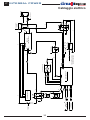
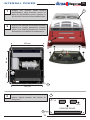
1
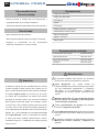
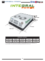
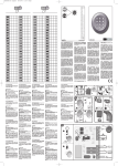
Air conditioning for vehicles
F-4218 rev.01
Instrucciones de Montaje
Mounting Instructions
Instructions de Montage
Montageanweisungen
Istruzioni di Montaggio
Kurulum Tali̇ matlari
ES
Spanish
EN
English
FR
French
GE
German
IT
Italian
TK
Turkish
0911860000
0911980000
ES
INTEGRAL POWER
Air conditioning for vehicles
Herramientas
Recomendaciones
Para el montaje
Juego de Llaves Torx
Juego de Llaves Allen
• Antes de iniciar el montaje leer las instrucciones y
Llave fija 10
seguirlas durante el proceso de instalacion.
Tijeras
Flexómetro
• Usar las herramientas adecuadas para cada operación.
Juego de carraca - boca Ø 10
Electricidad
Destornillador estrella / plano
Sierra circular Ø 35
• Desconectar la llave de contacto.
Taladro - boca Ø 7
• Desconectar la batería antes de empezar el montaje.
•
Asegurar
el
conexionado
de
los
Sierra vaivén
componentes
eléctricos, verificando su correcto encaje.
Documentación incluída
Instrucciones de montaje
091186-091198
Manual del usuario
220.AA2.1001
Diagnosis de averías
220.AA2.1002
Garantía
220.AA1.0010
! Advertencias
! El
personal instalador debe poseer una formación
! Atención
suficiente en Aire Acondicionado de vehículos.
! dirna
Bergstrom, s.l. queda exenta de
responsabilidad si se producen averías que procedan
de una inadecuada manipulación ó instalación
del equipo, ó por modificaciones y sustituciones
efectuadas sin nuestra expresa autorización por
escrito.
Al instalar el equipo de aire acondicionado en el techo
se debe proteger la parte superior de la cabina con un
paño ó manta protectora para evitar posibles arañazos.
Al instalar Integral Power en el techo hay que tener
en cuenta que, normalmente, las cabinas que vienen
! Equipo
precargado con gas refrigerante R-134a,
provistas de escotilla, tienen una estructura suficiente
(I.P. 12 V. 500 g. - I.P. 24 V 500 g ) (No manipular el
circuito de gas refrigerante).
para soportar el peso del equipo. Sin embargo, cuando
no ocurra así y sea necesario realizar corte en el techo
! Véase
procedimiento de garantía del producto
ó incluso si en el caso de llevar escotilla el material no
incluido en Diagnosis de Averías.
es lo suficientemente resistente (caso de techo de fibra,
! Véase
Manual de Usuario del equipo para el correcto
plástico, etc...) es el instalador el que debe decidir, bajo
funcionamiento del mando a distancia y del panel de
control.
su responsabilidad, sobre la necesidad de reforzar
el techo para evitar posibles deformaciones, roturas,
! Al
finalizar la instalación se debe entregar al usuario:
entradas de agua, etc... habilitando los medios para que
Manual del Usuario, Garantía y Diagnosis de
averías.
esto no ocurra.
2
INTEGRAL POWER
ES
Air conditioning for vehicles
218 mm
733 mm
655 mm
DATOS TÉCNICOS
Potencia
frigorífica
Tensión de
alimentación
Intensidad
absorbida
Caudal de
aire
Peso
total
3200 w
12V / 24V
30A / 45A **
700 m3/h
43,5 Kg
(**) Según norma JIS, condiciones de ensayo: temperatura exterior 35 ºC, temperatura retorno 27 ºC.
(**) Consumos extraídos de prueba con temperatura exterior entre 30 ºC y 42 ºC.
3
ES
INTEGRAL POWER
Air conditioning for vehicles
1
Posicionar el equipo Integral Power sobre el
techo, teniendo en cuenta que la posición final
debe corresponder con el frente suministrado
(0911860035) procurando que quede sobre
superficie plana.
2
Una vez definida la posición, quitar la carcasa
y marcar (6) taladros (Y) seguidamente hacer
coincidir los (4) taladros de la plantilla con (4)
taladros traseros del techo (figura 3).
1
Tener en cuenta la flecha que indica el
sentido de la marcha.
T
245 mm
393 mm
620 mm
Y
585 mm
3
Marcar los cortes y taladros y proceder a
realizarlos (proteger los cantos cortados con
antioxidante).
3
Ø 7 (4)
Ø 32
SENTIDO DE MARCHA
Y
4
INTEGRAL POWER
4
ES
Air conditioning for vehicles
Colocar junta cierre, juntas laterales y junta
frontal en la parte interior del compacto como
se muestra.
a
b
c
Junta cierre
Juntas laterales
Junta frontal
a
b
b
c
5
Pasar cableado por el traladro (T) realizado en
el techo para ello (figura 1). Colocar Integral
Power (A) con (6) casquillos de 13 mm,
arandelas de goma y (6) tornillos M6/100x40
(B) y tuercas M6/100.
!
Importante: Asegurar estanqueidad del
conjunto al techo para impedir posibles
entradas de agua.
5
5
A
B
6A
Colocar arandelas de goma para evitar paso
de agua.
6A
C
tuerca M6/100
arandela plana
arandela goma
base equipo
6B
casquillo
techo vehículo
arandela plana
Sellar taladros con silicona.
tornillo M6/100
5
ES
6C
INTEGRAL POWER
Air conditioning for vehicles
Colocar tubo PVC según necesidad de
longitud.
C
Cableado de excitación
!
Atención: El cableado de excitación se
instalará en todos los vehículos excepto en
camiones.
7
Colocar cableado de excitación por el
interior ó por el exterior del vehículo según
convenga.
7
6
7
INTEGRAL POWER
ES
Air conditioning for vehicles
8
Conectar el otro extremo en posición (+) sólo
con motor arrancado.
9
Conectar cableado al frente (Punto C página
5) y fijar frente con tornillos suministrados.
!
Importante: Antes de montar el frente,
colocar el interruptor en la posición
correcta para cada vehículo.
10
Conectar cable de alimentación superior en la
parte trasera del equipo.
11
Conectar cable de alimentación inferior (A)
llevándolo a batería y poner adhesivos de
peligro de unión de cableado en lugar visible
(B).
!
Importante: Al conectar los cableados, dejar
la distancia adecuada, para evitar su rotura
por los movimientos del vehículo.
!
Importante: Debido al complejo sistema de
regulación electrónica del equipo, la toma
de corriente debe realizarse directamente a
la batería del vehículo (si no fuese posible
consultar con dirna Bergstrom, s.l.).
!
Importante: Para la puesta en marcha consultar
el manual de usuario (220AA21001).
7
!
10
B
A
11
R
R
Az
85
87
8
ELECTRO
R
N
R
M
N
R
M
ELECTRO
86
30
RELE
COMPRESOR
R
B
B
N
N
B
N
N
R
N
B
N
M
R
A
A
N
Na
R
Na
R
A
ELECTRONICA
R Na N
Na
R
A
)+(
)-(
M
V
Az
MOTOR ARRANCADO
(+) POSITIVO CON
R
R
)+(
M
N
N
M
PRESURIZADOR
R
A
FUSIBLE
P
R
Az
COMPRESOR
MODULO
INTERRUPTOR
25A ----- 12v
15A ----- 24v
R
(+)
PRESOSTATO
Az
(+)
Az
R
A
(-)
(+)
M
R
V
Az
R
M
85
30
R
R
86
87
87a
RELE
)+(
)-(
CENTRO
CONEXIONES
R
R
)+(
)-(
BATERIA
FUSIBLE 50A
Az
INTEGRAL POWER
SONDA
RECIRCULACION
SONDA
ANTI-HIELO
FUSIBLE 5A
A
M
R
V
ES
Air conditioning for vehicles
Esquema eléctrico
INTEGRAL POWER
EN
Air conditioning for vehicles
Tools
Assembly
Recommendations
Torx wrenches set
Allen wrenches set
• Before starting assembly, please read instructions
and follow them during installation process.
Open-jawed spanner 10
Scissors
• Use the adequate tools for each operation.
Flexo-meter
Ø10 Wrench
Electricity
Phillips screwdriver / screwdriver
• Disconnect ignition key.
Ø35 Circular saw
• Disconnect battery before starting assembly.
Ø7 Drill
• Make sure electric components are securely
connected, checking their correct fitting.
Sabre saw
Documentation included
Mounting instructions
091186-091198
User’s guide
220.AA2.1001
Troubleshooting
220.AA2.1002
Warranty
220.AA1.0010
! Warnings
! The
installing personnel must have a sufficient
training in vehicles air conditioning.
! dirna
Bergstrom, s.l. shall not be responsible for
! Warning
breakdowns or damages coming from an inadequate
handling or installation of the equipment or from
When installing air conditioning equipment on roof, the
modifications and substitutions carried out without
upper cabin part must be protected with a cloth or a
our express and written authorisation.
protective blanket to avoid possible scratches. When
! Unit
pre-loaded with refrigerant gas R-134a, (
installing Integral Power on roof, take into account that,
I.P. 12 V. 500 g. - I.P. 24 V 500 g ) (Do not touch
normally, cabins equipped with a hatch have a strong
the refrigerant gas circuit).
enough structure to hold equipment weight. However,
! Please
see product warranty procedure included in
if it is not the case and it is necessary to carry out a
Troubleshooting.
cut in the roof or, although it has a hatch, the material
! Please
see equipment User’s Guide for its correct
is not resistant enough (if roof is made of fibre, plastic,
functioning of the remote control and control panel.
etc...), it is the installer who will have to decide, under
! Once
installation is finished, the following documents
his responsibility, if it is necessary to reinforce the roof to
avoid possible deformations, breaks, water entries, etc.,
must be handed over to the user: User’s Guide,
habilitating the means required to stop it from occurring.
Warranty and Troubleshooting.
9
EN
INTEGRAL POWER
Air conditioning for vehicles
218 mm
733 mm
655 mm
TECHNICAL DETAILS
Refrigerating
power
Working
voltage
Absorbed
intensity
Airflow
Total
weight
3200 w
12V / 24V
30A / 45A **
700 m3/h
43,5 Kg
(**) In accordance with JIS standard, test conditions: outside temperature 35ºC, return temperature 27ºC.
(**) Consumption as found in test with outside temperature between 30°C and 42°C.
10
INTEGRAL POWER
EN
Air conditioning for vehicles
1
Position the Integral Power unit on the roof,
taking into account that the final position must
correspond to the front supplied (0911860035),
ensuring it is on a flat surface.
2
Once the position is defined, remove the case
and mark (6) boreholes (Y), then align the (4)
template boreholes with the (4) rear boreholes
in the roof (figure 3).
1
Note the arrow indicating the operation
direction.
T
245 mm
393 mm
620 mm
Y
585 mm
3
Mark and make the cuts and boreholes (protect
the sharp edges with anti-oxidant).
3
Ø 7 (4)
Ø 32
SENTIDO DE
MARCHA
OPERATION
DIRECTION
Y
11
EN
INTEGRAL POWER
4
Air conditioning for vehicles
Position the seal joint, side seals and front
seal inside the compact as shown.
a
b
c
Seal joint
Side seals
Front seal
a
b
b
c
5
Pass the cabling through the borehole (T)
made for this purpose in the roof (figure 1).
Position Integral Power (A) with (6) 13 mm
pieces of bushing, rubber washers and (6)
M6/100x40 screws (B) and nuts M6/100.
!
Important: Ensure sealtightness between
the unit and the ceiling in order to prevent
any water coming in.
5
5
A
B
6A
Insert rubber washers to prevent water
passage.
6A
C
M6/100 nut
flat washer
rubber washer
unit base
6B
bushing
vehicle roof
flat washer
Seal the boreholes with silicone.
screw M6/100
12
INTEGRAL POWER
6C
Air conditioning for vehicles
EN
Place PVC pipe in the length required.
C
Excitation wiring
!
Attention: Wiring excitation install on all
vehicles except trucks.
7
Position the excitation wiring inside or
outside the vehicle as appropriate.
7
13
7
EN
INTEGRAL POWER
Air conditioning for vehicles
8
Connect the other end in (+) position with the
engine running.
9
Connect the wiring to the front (Point C page
12) and secure the front with the screws
supplied.
!
Important: Before mounting the front,
position the circuit breaker in the correct
position for each vehicle.
10
Connect the upper power cable in the rear of
the unit.
10
11
Connect the lower power cable (A) to the
battery and place cable joint hazard stickers in
a visible place (B).
B
!
Important: When connecting the cables, leave
suitable distance in order to prevent breakage
when the vehicle moves.
!
Important: Given the complex electronic
regulation system in the unit, the current
connection must be made directly to the
vehicle’s battery (if this is not possible, contact
dirna Bergstrom, s.l.).
!
Important: Check the user
(220AA21001) before starting up.
manual
14
!
A
11
15
RECIRCULATION
SONDA
SENSOR
RECIRCULACION
SONDA
ANTI-FREEZE
ANTI-HIELO
SENSOR
FUSIBLE
FUSE
5A5A
R
R
A
R
Az
85
87
ELECTRO
ELECTRO
R
N
R
M
N
R
M
ELECTRO
ELECTRO
86
30
RELAY
RELE
COMPRESOR
COMPRESSOR
R
B
B
N
N
B
N
N
R
N
B
N
M
R
M
A
A
N
Na
R
V
Na
R
A
ELECTRONICA
ELECTRONICS
R Na N
Na
R
A
)+(
)-(
M
V
Az
ENGINE
RUNNING
MOTOR
ARRANCADO
(+)PPOSITIVO
CON
(+)
OSITIVE WITH
R
)+(
M
R
N
N
M
PRESURIZADOR
PRESSURISER
R
(+)
A
FUSIBLE
FUSE
P
R
Az
MODULO
COMPRESSOR
MODULE
COMPRESOR
CIRCUIT
BREAKER
INTERRUPTOR
25A ----- 12v
15A ----- 24v
R
PRESOSTATO
PRESSOSTAT
Az
(+)
Az
R
A
(-)
(+)
M
R
V
Az
R
M
85
30
R
86
87
87a
RELAY
RELE
R
)+(
)-(
CENTRO
CONNECTIONS
CONEXIONES
CENTER
R
R
)+(
)-(
BATERIA
BATTERY
FUSE 50A
FUSIBLE
50A
Az
INTEGRAL POWER
Air conditioning for vehicles
EN
Electric wiring
FR
INTEGRAL POWER
Air conditioning for vehicles
Outils
Recommendations
Pour Le Montage
Jeu de clés Torx
Jeu de clés Allen
• Avant de commencer le montage de l’appareil, prière
de lire les instructions et de les suivre attentivement.
Clé fixe 10
• Utiliser les outils convenant à chaque opération.
Mètre
Ciseaux
Jeu de clés à cliquet - mèche Ø 10
Electricity
Tournevis étoile / tournevis
• Déconnecter la clé de contact.
Scie circulaire Ø 35
• Déconnecter la batterie avant de commencer le
montage.
Scie sauteuse
Perceuse - mèche Ø 7
• Vérifier le câblage des composants électriques et
leur correcte installation.
Documentation included
Instructions de montage
091186-091198
Guide de l’utilisateur
220.AA2.1001
Solution des problèmes
220.AA2.1002
Garantie
220.AA1.0010
! Garantie
! L’installateur
devra posséder la formation pertinente
en air conditionné sur véhicules.
! dirna
Bergstrom, s.l., ne sera pas responsable
! Attention
des dommages ou des bris dérivés d’une
installation ou d’une manipulation incorrecte ni
Lors de l’installation de l’appareil d’air conditionné
des modifications réalisées sans autorisation
sur le toit, il faudra protéger la partie supérieure
expresse par écrit.
de la cabine avec un linge ou une couverture de
protection afin d’éviter les éventuelles égratignures.
! Équipement
préchargé avec du gaz réfrigérant
Durant l’installation du Integral Power, tenir compte
R-134a, ( I.P. 12 V. 500 g. - I.P. 24 V 500 g ) (Ne pas
du fait que normalement les cabines pourvues
manipuler le circuit de gaz réfrigérant).
d’écoutille possède une structure suffisamment
! Voir
la procédure de garantie du produit au
solide pour supporter le poids de l´appareil.
Diagnostic de problèmes.
Cependant, si ce n’est pas le cas et qu’il est
! Voir
le Guide de l’Usager de l’appareil pour le
nécessaire de découper le toit ou même si disposant
fonctionnement correcte de la télécommande et du
d’écoutille, la structure n’est pas suffisamment rigide
tableau de commande.
(si elle était en fibre, plastique, etc.) il appartiendra à
l’installateur de décider s’il faut renforcer le toit pour
! A
près l’installation, vous devez fournir à l’utilisateur:
éviter toute déformation, rupture ou voie d’eau, etc.,
Manuel d’utilisation, garantie et diagnostic de
et prendre les mesures nécessaires à cet effet.
pannes.
16
INTEGRAL POWER
FR
Air conditioning for vehicles
218 mm
733 mm
655 mm
DONNÉES TECHNIQUES
Puissance
frigorifique
Tension
d’alimentation
Intensité
absorbée
Débit d’air
Poids
total
3200 w
12V / 24V
30A / 45A **
700 m3/h
43,5 Kg
(**) Selon norme JIS, conditions d’essai : température extérieure 35 ºC, température retour 27 ºC.
(**) Consommations extraites de l’essai avec une température extérieure d’entre 30 ºC et 42 ºC.
17
FR
INTEGRAL POWER
Air conditioning for vehicles
1
Situer l’équipement Integral Power sur le
plafond. La position finale doit correspondre à
la partie frontale fournie (0911860035). Il doit
être placé sur une surface plate.
2
Une fois que la position est définie, retirer
la carcasse et marquer (6) trous (Y) et faire
ensuite coïncider les (4) trous du patron avec
les (4) trous arrières du plafond (figure 3).
1
Tenir compte de la flèche qui indique le
sens de la course.
T
245 mm
393 mm
620 mm
Y
585 mm
3
Marquer les coupes et les trous et les
réaliser (protéger les bords coupés avec de
l’antioxydant).
3
Ø 7 (4)
Ø 32
SENTIDO
DE COURSE
MARCHA
SENS
DE LA
Y
18
INTEGRAL POWER
4
FR
Air conditioning for vehicles
Placer le joint d’étanchéité, les joints latéraux
et le joint frontal sur la partie intérieure du
Compact comme cela est indiqué.
a
b
c
Joint étanchéité
Joints latéraux
Joint frontal
a
b
b
c
5
Passer le câblage à travers le trou (T) réalisé
sur le plafond à cet effet (figure 1). Placer
ensuite l’Integral Power (A) avec (6) douilles
de 13 mm, des rondelles en caoutchouc et (6)
vis M6/100x40 (B) et écrous M6/100.
!
Important : assurer l’étanchéité de
l’ensemble sur le plafond pour éviter de
possibles entrées d’eau.
5
5
A
B
6A
Placer les rondelles en caoutchouc pour éviter
le passage de l’eau.
6A
C
écrou M6/100
rondelle plate
rondelle caoutchouc
base équipement
6B
douille
plafond véhicule
rondelle plate
Sceller les trous avec de la silicone.
vis M6/100
19
FR
INTEGRAL POWER
6C
Air conditioning for vehicles
Placer un tuyau en PVC en fonction des
besoins de longueur.
C
Câblage d’excitation
!
Attention: l’installation de câblage d’excitation
sur tous les véhicules sauf les camions.
7
Placer le câblage d’excitation à l’intérieur
et à l’extérieur du véhicule, selon les
besoins.
7
20
7
INTEGRAL POWER
FR
Air conditioning for vehicles
8
Connecter l’autre extrémité sur la position (+)
seulement avec le moteur en marche.
9
Connecter le câblage à la partie avant (Point C
page 19) et fixer l’avant avec les vis fournies.
!
Important : avant de monter la partie avant,
il faut placer l’interrupteur sur la position
correcte pour chaque véhicule.
10
Connecter le câble d’alimentation supérieur à
la partie arrière de l’équipement.
11
Connecter le câble d’alimentation inférieur
(A) en le menant à la batterie et placer des
adhésifs de danger d’union de câblage sur un
lieu visible (B).
!
Important: Au moment de connecter les
câblages, prévoir une distance suffisante pour
éviter leur rupture à cause des mouvements
du véhicule.
!
Important: En raison de la complexité
du système de réglage électronique de
l’équipement, la prise de courant doit se
réaliser directement à la batterie du véhicule
(si cela n’est pas possible, contacter dirna
Bergstrom, s.l.).
!
Important : Pour la mise en marche, consultez
le manuel de l’usager (220AA21001).
21
!
10
B
A
11
R
R
Az
85
87
22
ELECTRO
ELECTRO
R
N
R
M
N
R
M
ELECTRO
ELECTRO
86
30
RELAIS
RELE
B
B
N
N
B
N
N
R
N
B
N
M
R
A
A
N
Na
R
Na
R
A
ELECTRONICA
ELECTRONIQUE
R Na N
Na
R
A
)+(
)-(
M
V
Az
(+) P
POSITIVO
(+)
OSITIFCON
AVEC MOTEUR
DÉMARRÉ
MOTOR
ARRANCADO
R
R
)+(
M
N
N
M
PRESURIZADOR
PRESURISEUR
R
(+)
A
Az
MODULE
COMPRESSEUR
COMPRESOR
MODULO
25A ----- 12v
15A ----- 24v
R
A
INTERRUPTEUR
INTERRUPTOR
FUSIBLE
FUSIBLE
P
PRESOSTATO
PRESSOSTAT
Az
(+)
Az
R
R
(-)
(+)
M
R
V
Az
R
M
85
30
R
86
87
87a
RELE
RELAY
R
)+(
)-(
CENTRO
CONNECTIONS
CENTER
CONEXIONES
R
R
)+(
)-(
BATERIA
BATTERIE
FUSIBLE
FUSIBLE50A
50A
Az
INTEGRAL POWER
SONDE
SONDA
RECIRCULACION
RECIRCULATION
SONDA
SONDE
ANTI-HIELO
ANTIGEL
FUSIBLE
FUSIBLE5A
5A
R
COMPRESOR
COMPRESSEUR
A
M
R
V
FR
Air conditioning for vehicles
Câblage electrique
INTEGRAL POWER
GE
Air conditioning for vehicles
Werkzeuge
Empfehlungen
Zur montage
Torx-Schraubenschlüssel
Inbusschraubenschlüssel
•
Vor und während der Montage bitte diese
Anweisungen lesen und beachten.
10er Schraubenschlüssel
Schere
• Benutzen Sie für jeden Arbeitsschritt die geeigneten
Werkzeuge.
Metermaß
Drehmomentratsche - Ø 10
Kreuzschraubendreher / Schraubendreher
Elektrizität
Kreissäge Ø 35
• Zündschlüssel abziehen.
Bohrer - Ø 7
• Vor Montagebeginn die Batterie abklemmen.
Stichsäge
• Den ordnungsgemäßen Anschluss und die korrekte
Installation der Elektrokomponenten überprüfen.
Mitgelieferte unterlagen
Montageanweisungen
091186-091198
Benutzerleitfaden
220.AA2.1001
Fehlerdiagnose
220.AA2.1002
Garantie
220.AA1.0010
! Warnhinweise
! Der
Installateur muss im Bereich Fahrzeug-Klimaanlagen
ausreichend geschult sein.
! Achtung
! dirna
Bergstrom, s.l. übernimmt keine Verantwortung
für
Wird die Klimaanlage im Kabinendach installiert,
muss der obere Teil der Kabine mit einem Tuch oder
einer Decke gegen eventuelle Kratzer geschützt
werden. Bei der Installation der Compact auf
dem Kabinendach muss darauf geachtet werden,
dass mit Luken ausgestattete Kabinen über eine
ausreichend stabile Struktur verfügen, um das
Gewicht des Geräts Stand zu halten. Sollte das
Fahrzeug über keine Luke verfügen und sollte es
notwendig sein, das Kabinendach aufzuschneiden,
bzw. sollte die vorhandene Struktur nicht ausreichend
stabil sein (z.B. wenn sie aus Faser, Kunststoff
usw. hergestellt ist), obliegt es dem Installateur zu
entscheiden, ob das Kabinendach zur Vermeidung
von Verformungen, Brüchen, undichten Stellen usw.
verstärkt werden muss, und die hierfür notwendigen
Mittel bereit zu stellen.
Schäden
oder
Brüche
aufgrund
einer
nicht
ordnungsgemäßen Installation oder Bedienung des
Geräts oder den Austausch von Teilen bzw. Umbauten,
die ohne die erforderliche schriftliche Genehmigung
durchgeführt wurden.
! Mit
Kühlgas R-134a, ( I.P. 12 V. 500 g. - I.P. 24 V
500 g ) vorgekühltes Gerät (Kühlgaskreislauf nicht
manipulieren).
! Siehe
Garantieverfahren des Produkts in der
Fehlerdiagnose.
! Siehe
Benutzerleitfaden
des
Geräts
für
den
ordnungsgemäßen Betrieb der Fernbedienung und des
Bedienfelds.
! Die
folgenden Unterlagen müssen dem Benutzer nach der
Installation ausgehändigt werden: Benutzerleitfaden,
Garantie und Fehlerdiagnose.
23
GE
INTEGRAL POWER
Air conditioning for vehicles
218 mm
733 mm
655 mm
TECHNISCHE DATEN
Kühlleistung
Speisespannung
Aufgenommene
Stromstärke
Luftdurchsatz
Gesamtgewicht
3200 w
12V / 24V
30A / 45A **
700 m3/h
43,5 Kg
(**) Gemäss JIS-Norm, Prüfbedingungen: Außentemperatur 35 ºC, Rücklauftemperatur 27 ºC.
(**) Verbräuche entsprechend Prüfung bei Außentemperatur zwischen 30 ºC und 42 ºC.
24
INTEGRAL POWER
GE
Air conditioning for vehicles
1
Integral Power auf einer ebenen Fläche
auf
dem
Dach
positionieren.
Dabei
berücksichtigen, dass die endgültige Position
mit der mitgelieferten Front (0911860035)
übereinstimmen muss.
2
Nach Festlegung der Position, das Gehäuse
abnehmen und (6) Löcher (Y) markieren.
Danach die (4) Bohrlöcher der Vorlage mit
(4) hinteren Löchern des Dachs (Abb. 3) in
Übereinstimmung bringen.
1
Auf den Pfeil achten, der die Fahrtrichtung
anzeigt.
T
245 mm
393 mm
620 mm
Y
585 mm
3
Die Schnitte und Bohrlöcher markieren
und durchführen (die Schnittkanten mit
Rostschutzmittel schützen).
3
Ø 7 (4)
Ø 32
SENTIDO
DE MARCHA
FAHRTRICHTUNG
Y
25
GE
4
INTEGRAL POWER
Air conditioning for vehicles
Verschlussdichtung,
Seitendichtungen
und Frontdichtung auf der Innenseite der
Kompaktanlage wie gezeigt anbringen.
a
b
c
Verschlussdichtung
Seitendichtungen
Frontdichtung
a
b
b
c
5
Kabel durch das hierfür angefertigte Bohrloch
(T) führen (Abb. 1). Integral Power (A) mit
(6) 13 mm Hülsen, Gummischeiben und
(6) Schrauben M6/100x40 (B) und Muttern
M6/100 anbringen.
!
Wichtiger
Hinweis:
Dichtigkeit
der
Baugruppe zum Dach hin sicherstellen, um
möglichen Wassereintritt zu verhindern.
5
5
A
B
6A
Gummiunterlegscheiben zur Vermeidung von
Wassereintritt anbringen.
6A
C
Mutter M6/100
Flachscheibe
Gummiunterlegscheibe
Gerätesockel
6B
Hülse
Fahrzeugdach
Flachscheibe
Bohrlöcher mit Silikon abdichten.
Schraube M6/100
26
INTEGRAL POWER
6C
Air conditioning for vehicles
GE
PVC-Rohr je nach Längebedarf.
C
Erregerkabel
!
Achtung: Wiring Anregung Installation auf
alle Fahrzeuge außer LKW.
7
Erregerkabel innerhalb oder außerhalb des
Fahrzeugs verlegen.
7
27
7
GE
INTEGRAL POWER
Air conditioning for vehicles
8
Das andere Ende nur bei angelassenem
Motor auf (+) stellen.
9
Kabel an Frontteil anschließen (Punkt C,
Seite 5) und Frontteil mit den mitgelieferten
Schrauben befestigen.
!
Wichtig: Vor Montage des Frontteils den
Schalter auf die für das jeweilige Fahrzeug
richtige Position stellen.
10
Oberes Stromkabel an der Hinterseite des
Geräts anschließen.
11
Unteres Stromkabel (A) anschließen und zur
Batterie führen und Gefahrenaufkleber für die
Kabelverbindung an einem sichtbaren Ort (B)
anbringen.
!
Wichtiger Hinweis: Beim Anschluss der
Kabel ausreichenden Abstand lassen, um
deren Bruch durch die Bewegungen des
Fahrzeugs zu vermeiden.
!
Wichtiger Hinweis: Aufgrund des komplexen
elektronischen Regelsystems des Geräts
muss der Stromanschluss direkt an die
Fahrzeugbatterie erfolgen (falls dies nicht
möglich ist, setzen Sie sich bitte mit dirna
Bergstrom, s.l. in Verbindung).
!
Wichtiger Hinweis: Für die Inbetriebnahme,
lesen Sie bitte im Benutzerhandbuch
(220AA21001) nach.
28
!
10
B
A
11
29
SONDA
RÜCKFÜHRSONDE
RECIRCULACION
SONDA
FROSTSANTI-HIELO
CHUTZFÜHLER
FUSE 5A5A
FUSIBLE
R
R
A
R
Az
85
87
ELECTRO
ELEKTRO
R
N
R
M
N
R
M
ELEKTROGEBLÄSE
ELECTRO
86
30
RELE
RELAIS
COMPRESOR
KOMPRESSOR
R
B
B
N
N
B
N
N
R
N
B
N
M
R
M
A
A
N
Na
R
V
Na
R
A
ELECTRONICA
ELEKTRONIK
R Na N
Na
R
A
)+(
)-(
M
V
Az
(+)(+)PPOSITIVO
OSITIV BEI
CON
ANGELASSENEM
MOTOR ARRANCADOMOTOR
R
R
)+(
M
N
N
M
PRESURIZADOR
DRUCKHALTER
R
(+)
A
FUSIBLE
FUSE
P
MODULO
Az
COMPRESSOR
COMPRESOR
MODULE
R
INTERRUPTOR
SCHALTER
25A ----- 12v
15A ----- 24v
R
DRUCKWÄCHTER
PRESOSTATO
Az
(+)
Az
R
A
(-)
(+)
M
R
V
Az
R
M
85
30
R
86
87
87a
RELE
RELAIS
R
)+(
)-(
R
ZENTRUM
CENTRO
CONEXIONES
VERBINDUNGEN
R
)+(
)-(
BATERIA
BATTERIE
FUSIBLE
50A
FUSE 50A
Az
INTEGRAL POWER
Air conditioning for vehicles
GE
ElektrischeVerkabelung
IT
INTEGRAL POWER
Air conditioning for vehicles
Attrezzi
Suggerimenti
per il montaggio
Kit di chiavi Torx
Kit di chiavi Allen
• Prima di cominciare il montaggio, leggere attentamente
Chiave fissa 10
le istruzioni e rispettarle nel corso dello stesso.
Forbici
Metro a nastro
• Usare gli attrezzi più adatti ad ogni operazione.
Set chiavi a cricchetto - bocca Ø 10
Elettricitá
Cacciavite stella / cacciavite
Sega circolare Ø 35
• Scollegare la chiave di contatto.
Trapano - bocca Ø 7
•S
collegare la batteria prima di cominciare il montaggio.
•A
ssicurarsi
di
aver
effettuato
Sega a svolgere
correttamente
l’installazione e il collegamento dei componenti elettrici.
Documentazione allegata
Istruzioni di montaggio
091186-091198
Guida dell’utente
220.AA2.1001
Soluzione dei problemi
220.AA2.1002
Garanzia
220.AA1.0010
! Avvertenze
! L’installatore
deve essere in possesso della
formazione necessaria in materia di aria condizionata
! Attenzione
per veicoli.
! dirna
Bergstrom, s.l. declina ogni responsabilità
Quando si installa l’impianto di aria condizionata
sul tettuccio, bisogna proteggere la parte superiore
della cabina con uno straccio o una coperta per
evitare eventuali graffi. Per l’installazione del
Integral Power, tenere presente che normalmente
le cabine munite di oblò dispongono di una
struttura abbastanza solida per sostenere il peso
dell’impianto. Tuttavia, se così non fosse e se fosse
necessario tagliare il tettuccio, o se in presenza
di oblò la struttura non fosse abbastanza rigida
(se fosse di fibra, plastica, ecc.), è responsabilità
dell’installatore decidere se occorre rinforzare il
tettuccio per evitare qualsiasi deformazione, rottura
o penetrazione d’acqua, ecc., prendendo le misure
necessarie per evitarlo.
per danni o rotture derivanti dall’errata installazione
o dall’errato uso dell’impianto o da sostituzioni
o modifiche effettuate senza la necessaria
autorizzazione per iscritto.
! Dispositivo
precaricato con gas refrigerante
R-134a, ( I.P. 12 V. 500 g. - I.P. 24 V 500 g ) (Non
manomettere il circuito di gas refrigerante).
! Vedi
la procedura di garanzia del prodotto in
Diagnosi dei problemi.
! Vedi
la Guida dell’utente dell’impianto per il corretto
funzionamento del telecomando e del pannello di
controllo.
! I seguenti documenti devono essere consegnati
all’utente una volta conclusa l’installazione: Guida
dell’utente, Garanzia e Diagnosi dei problemi.
30
INTEGRAL POWER
IT
Air conditioning for vehicles
218 mm
733 mm
655 mm
DATI TECNICI
Potenza
frigorifera
Tensione di
alimentazione
Intensità
assorbita
Portata
d’aria
Peso
totale
3200 w
12V / 24V
30A / 45A **
700 m3/h
43,5 Kg
(**) Secondo la norma JIS, condizioni di test: temperatura esterna 35ºC, temperatura ritorno 27º C.
(**) Consumi testati con temperatura esterna tra 30º C e 42 ºC.
31
IT
INTEGRAL POWER
Air conditioning for vehicles
1
Posizionare l’impianto Integral Power sul
tettuccio, tenendo conto che la posizione
finale deve coincidere con il frontalino in
dotazione (0911860035) facendo in modo che
sia livellato sulla superficie.
2
Una volta determinata la posizione, rimuovere
l’involucro e segnare i (6) fori (Y) e quindi fare
coincidere i (4) fori della dima con i (4) fori
posteriori del tettuccio (figura 3).
1
Tenere conto della freccia che indica il
senso di marcia.
T
245 mm
393 mm
620 mm
Y
585 mm
3
Segnare i tagli e i fori e quindi eseguirli
(proteggere
i
bordi
tagliati
con
antiossidante).
3
Ø 7 (4)
Ø 32
SENSO DI MARCIA
Y
32
INTEGRAL POWER
4
IT
Air conditioning for vehicles
Montare la guarnizione di chiusura, le
guarnizioni laterali e quella frontale nella parte
interna, come illustrato nella figura.
a
b
c
Guarnizione di chiusura
Guarnizioni laterali
Guarnizione frontale
a
b
b
c
5
Far passare il cablaggio nell’apposito foro
(T) sul tettuccio (figura 1). Fissare l’Integral
Power (A) con (6) boccole da 13 mm, le
rondelle di gomma e (6) viti M6/100x40 (B) e i
dadi M6/100.
!
Nota bene: Verificare la tenuta dell’insieme
sul tettuccio per evitare eventuali
infiltrazioni d’acqua.
5
5
A
B
6A
Inserire le rondelle di gomma per evitare
l’infiltrazione dell’acqua.
6A
C
Dado M6/100
Rondella piana
Rondella di gomma
Base del dispositivo
6B
Boccola
Tettuccio del veicolo
Rondella piana
Sigillare i fori con silicone.
Vite M6/100
33
IT
6C
INTEGRAL POWER
Air conditioning for vehicles
Montare il tubo di PVC alla lunghezza
necessaria.
C
Cablaggio d’eccitazione
!
Attenzione: eccitazione installazione di
un cavo su tutti i veicoli ad eccezione di
camion.
7
Montare il cablaggio di eccitazione
dall’interno o dall’esterno del veicolo a
seconda della convenienza.
7
34
7
INTEGRAL POWER
IT
Air conditioning for vehicles
8
Collegare l’altra estremità in posizione (+)
solo con il motore acceso.
9
Collegare il cablaggio al frontalino (Punto C
pagina 33) e fissare il frontalino con le viti in
dotazione.
!
Nota bene: prima di montare il frontalino,
posizionare correttamente l’interruttore a
seconda del veicolo.
10
Collegare il cavo di alimentazione superiore
alla parte posteriore dell’impianto.
11
Collegare il cavo di alimentazione inferiore (A)
portandolo fino alla batteria e applicare in un
posto visibile gli adesivi indicanti il pericolo che
comporta la connessione del cablaggio (B).
!
Nota bene: Per collegare i cablaggi, lasciare
una distanza adeguata per evitarne la rottura
a causa dei movimenti del veicolo.
!
Nota bene: Dato il complesso sistema di
regolazione elettronica dell’impianto, la
corrente deve essere presa direttamente dalla
batteria del veicolo (se ciò non fosse possibile,
si prega di interpellare dirna Bergstrom, s.l.).
!
Nota bene: Per l’avviamento, vedi il Manuale
dell’utente (220AA21001).
35
!
10
B
A
11
R
R
R
Az
85
87
36
ELECTRO
ELECTRO
R
N
R
M
N
R
M
ELECTRO
ELECTRO
86
30
RELE
RELÈ
COMPRESOR
COMPRESSORE
A
B
B
N
N
B
N
N
R
N
B
N
M
R
M
A
A
N
Na
R
Na
R
A
ELECTRONICA
ELETTRONICA
R Na N
Na
R
A
)+(
)-(
M
V
Az
(+) POSITIVO
CONCON IL
(+)
POSITIVO
MOTORE
ACCESO
MOTOR
ARRANCADO
R
R
)+(
M
N
N
M
PRESSURIZZATORE
PRESURIZADOR
R
(+)
A
Az
MODULO
COMPRESSORE
COMPRESOR
MODULO
25A ----- 12v
15A ----- 24v
R
R
INTERRUPTOR
INTERRUTTORE
FUSIBLE
FUSIBILE
P
PRESOSTATO
PRESSOSTATO
Az
(+)
Az
R
A
(-)
(+)
M
R
V
Az
R
M
85
30
R
86
87
87a
RELE
RELÈ
R
)+(
)-(
CENTRO
COLLEGAMENTI
CONEXIONES
CENTER
R
R
)+(
)-(
BATERIA
BATTERIA
FUSIBILE50A
50A
FUSIBLE
Az
INTEGRAL POWER
SONDA
SONDADI
RECIRCULACION
RICIRCOLO
SONDA
SONDA
ANTI-HIELO
ANTI-GELO
FUSIBLE 5A
5A
FUSIBILE
R
V
IT
Air conditioning for vehicles
Cablaggio elettrico
INTEGRAL POWER
TK
Air conditioning for vehicles
Alet-edevatlar
Montaj için
Tavsiyeler
Torx anahtar takımı
Allen anahtar takımı
• Montaja başlamadan önce talimatları okuyun ve kurulum
Anahtar 10
işlemi süresince bunlara uyun.
Makaslar
Fleksometre
• Herbir işlem için uygun alet-edevatları kullanın.
Cırcır anahtar - ağız Ø 10
Elektrik
Tornavida yıldız / düz
Daire testere Ø 35
• Kontak anahtarını kapatın.
Matkap - ağız Ø 7
• Montaja başlamadan önce batarya bağlantısını kesin.
Kıl testere
• Elektrik bileşenlerinin bağlantılarının uygun şekilde
olmasını sağlayın.
Dokümantasyon
Montaj talimatları
091186-091198
Kullanım kılavuzu
220.AA2.1001
Arıza teşhisi
220.AA2.1002
Garanti
220.AA1.0010
! Uyarılar
! Kurulumu
yapan kişi, araç klimaları konusunda yeterli
bir eğitimden geçmiş olmalıdır.
! Dikkat
! dirna
Bergstrom, s.l. bozulmaların cihazın
uygunsuz manipülasyon ya da yanlış kurulumundan
kaynaklanması ya da modifikasyon ve değişikliklerin
şirketimizin yazılı izni olmadan yapılması durumunda
ortaya çıkabilecek olumsuzluklardan sorumlu
tutulamaz.
Klima cihazını kabinin üstüne monte ederken, kabinin üst
tarafı bir pano ya da koruyucu bez ile olası çizilmelere
karşı korunmalıdır.
Integral Power kabinin üstüne
monte edilirken normalde kabin kaportasının cihazı
! Cihaza
önceden gaz yüklenmiştir R-134a, (I.P. 12
destekleyecek yeterli yapısal dirence sahip olduğu
V. 500 g. - I.P. 24 V 500 g) (Soğutucu gaz devreleri
manipüle edilmemelidir).
dikkate alınmalıdır. Ancak, durumun bu şekilde olmaması
halinde, kabinin üstünde kesim yapılmasının gerekli
! Arıza
Teşhisi dahil ürünün garanti sürecine bakınız.
olması durumunda ya da malzemenin yeteri kadar sağlam
! Uzaktan
kumandanın ve kontrol panelinin doğru
olmaması durumunda (kabin tavanının elyaf, plastik vb.
çalıştırılması için Kullanım Kılavuzuna bakınız.
yapılmış olması…) olası deformasyonları, kırılmaları, su
! Kurulumdan
sonra kullanıcıya şunlar sunulmalıdır:
girmesini vb… önlemek, kabin çatısını güçlendirmek,
Kullanım Kılavuzu, Garanti ve Arıza teşhisi.
kurulumu yapanın sorumluluğu altındadır.
37
TK
INTEGRAL POWER
Air conditioning for vehicles
218 mm
733 mm
655 mm
TEKNİK ÖZELLİKLER
Soğutma Gücü
Çalışma
Gerilimi
Soğurma
Yoğunluğu
Hava Akışı
Toplam Ağırlık
3200W
12/24 V
30A / 45A**
700 m3/Saat
46,5 Kg.
(**) JIS standartları uyarınca test koşulları: 33C dış ortam sıcaklığı, 27 C dönüş sıcaklığı
(**) 30 – 42 C arası dış ortam sıcaklığında icra edilen testlerde bulunan sarfiyat değerleri
38
INTEGRAL POWER
TK
Air conditioning for vehicles
1
Entegre Güç Ünitesini kapak kısmına
konumlandırın. Nihai konumun verilen ön
bölüm ile (0911860035) uyumlu olmasına ve
düz bir zemin üzerinde olmasına dikkat ediniz.
2
Konumu belli olduktan sonra kasa korumasını
kaldırınız ve yuvaları işaretleyiniz. Ardından
şablon yuva deliklerini kapak kısmı üzerinde
bulunan arka yuva delikleri ile hizalandırınız.
1
T
245 mm
393 mm
620 mm
Y
585 mm
3
Yuva deliklerini işaretleyiniz ve kesimlerini
yapınız. (Keskin kenarları anti oksidan ile
koruyunuz.)
3
Ø 7 (4)
Ø 32
İLERLEME SENSE
Y
39
TK
INTEGRAL POWER
4
Air conditioning for vehicles
Conta ek yerini, gösterildiği şekilde kasa içinde
yan ve ön contalar ile konumlandırınız.
a
b
c
Conta Eki
Yan Conta
Ön Conta
a
b
b
c
5
Kabloları, bu amaçla açılmış ve kapak
kısmında bulunan yuva deliklerinden geçirin.
(Şekil 1)Entegre Güç Ünitesini (A) 13 mm.
Kılavuzlar (6), lastik pullar, vidalar (M6/100*40)
(6) ve M6/100 somunlar ile konumlandırın.
!
ÖNEMLİ: Ana ünite ile Kapak kısmı
arasındaki conta sıkılığından, suyun içeri
sızmasını önlemek açısından emin olunuz.
5
5
A
B
6A
Suyun geçişini önlemek için lastik pulları
yerleştiriniz.
6A
C
somun M6/100
düz yıkayıcı
lastik yıkama
bilgisayar baz
6B
kabuk
Araç çatı
düz yıkayıcı
Yuva deliklerini silikon ile kapatınız.
vida M6/100
40
INTEGRAL POWER
6C
Air conditioning for vehicles
TK
Gerekli uzunlukta PVC boruyu yerleştiriniz.
C
Çikiş kablolamasi
!
Dikkat: Çıkış kabloları, kamyonlar dışındaki
tüm araçlara kurulmalıdır.
7
Çıkış kablolarını uygun olduğu şekilde aracın
içine veya dışına konumlandırınız.
7
41
7
TK
INTEGRAL POWER
Air conditioning for vehicles
8
Diğer ucu, çalışmakta olan motorun (+)
kısmına bağlayınız.
9
Kablo şebekesini Sayfa 5 C de görüldüğü gibi
ön tarafa bağlayınız ve paketten çıkan vidalar
ile sıkılaştırınız.
!
ÖNEMLİ: Ön tarafı yerleştirmeden önce her
bir araç için akım anahtarını doğru konuma
getiriniz.
10
Ünitenin arka tarafında bulunan Üst kısım güç
kablosunu bağlayınız.
10
11
Alt kısım güç kablosunu (A), aküye bağlayınız
ve kablo bağlantı sı risk işaretçilerini görünür
bir yere yapıştırınız. (B)
B
!
ÖNEMLİ: Kabloları bağlarken araç hareket
ettiğinde oluşabilecek kırılmaları önlemek için
uygun mesafe bırakınız.
!
ÖNEMLİ: Ünite içerisinde yer alan karmaşık
elektronik düzenleyici sistem göz önüne
alındığında akım bağlantısı doğrudan aracın
aküsüne yapılmalıdır. (Bu mümkün değil ise
lütfen dirna Sa ile temas kurunuz)
!
ÖNEMLİ: Başlatmadan önce lütfen Kullanma
Kılavuzu (220AA21001) e göz atınız.
42
!
A
11
43
SONDA
RECIRCULACION
SONDA
ANTI-HIELO
FUSIBLE 5A
R
R
A
R
Az
85
87
ELECTRO
R
N
R
M
N
R
M
ELECTRO
86
30
RELE
COMPRESOR
R
B
B
N
N
B
N
N
R
N
B
N
M
R
M
A
A
N
Na
R
V
Na
R
A
ELECTRONICA
R Na N
Na
R
A
)+(
)-(
M
V
Az
MOTOR ARRANCADO
(+) POSITIVO CON
R
R
)+(
M
N
N
M
PRESURIZADOR
R
A
FUSIBLE
P
R
Az
COMPRESOR
MODULO
INTERRUPTOR
25A ----- 12v
15A ----- 24v
R
(+)
PRESOSTATO
Az
(+)
Az
R
A
(-)
(+)
M
R
V
Az
R
M
85
30
R
R
86
87
87a
RELE
)+(
)-(
CENTRO
CONEXIONES
R
R
)+(
)-(
BATERIA
FUSIBLE 50A
Az
INTEGRAL POWER
Air conditioning for vehicles
TK
Elektrik şeması
Ed:
13/05/2011
Md:
20/10/2014
c
Air conditioning for vehicles
Francisco Alonso, 6
28806 Alcalá de Henares, Madrid
SPAIN
CENTRO DE COMUNICACIONES
COMUNICATION CENTRE
NACIONAL
Centralita /Asistencia Técnica ............................ 918775841
Comercial .............................................................. 918775840
Fax ......................................................................... 918836321
Email.......................................................comercial@dirna.com
INTERNATIONAL
Tec. Assistance ............................................ 0034 918775848
Fax ................................................................ 0034 918836514
Email:........................................................... [email protected]
Export Dept. ................................................. 0034 918775846
Fax..................................................................0034 918771158
www.dirna.com
www.bycool.com
!
ATENCIÓN:
Dirna Bergstrom se reserva el derecho de efectuar modificaciones en cualquier momento de los datos
contenidos en esta publicación, por razones técnicas o comerciales.
!
NOTE:
For technical and commercial reasons, Dirna Bergstrom reserves the right to change the data contained
in this brochure.
!
ATTENTION:
Dirna Bergstrom se réserve le droit d´effectuer à tout moment des modifications des données reprises
sur cette publication, pour des raisons techniques ou commerciales.
!
HIWEIS:
Dirna Bergstrom behält sich vor, aus technischen oder kaufmännischen Gründen jederzeit Änderungen
der Angaben dieser Veröffentlichung vorzunehmen.
!
ATTENZIONE:
Dirna Bergstrom si riserva il diritto di effettuare modifiche in qualsiasi momento ai dati contenuti in questa
pubblicazione, per motivi tecnici o commerciali.