1
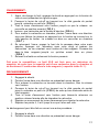
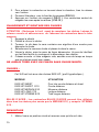
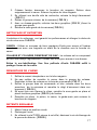
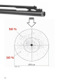
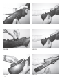
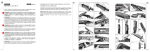
OWNER’S MANUAL
MANUALE DI ISTRUZIONI
MANUEL D’UTILISATION
xlr
ENGLISH
ITALIANO
FRANÇAIS
p. 1
p. 7
p. 14
SAFETY RULES
WARNING: READ THESE SAFETY RULES & OPERATORS MANUAL
BEFORE HANDLING YOUR FIREARM
Never point a firearm at anyone and always keep the muzzle pointed in a safe
direction.
Always treat all firearms as if they are loaded. Don’t rely on your gun’s “safety”.
Firearms should be unloaded when not in use and stored in a safe and secure location.
Keep firearms and ammunition away from children.
Use correct ammunition. Only use ammunition that exactly matches the caliber or
gauge markings on your firearm.
Always wear ear and eye protection when shooting.
Be sure the barrel is clear of obstructions before shooting.
Never load your firearm until you are in a location where it is safe to shoot. Always
keep the safety engaged until you are ready to shoot.
Keep your finger off the trigger while loading or unloading the shotgun.
If your gun fails to fire, keep it pointed in a safe direction, then unload it carefully
avoiding exposure to breech. If your gun fires, but the report or recoil seem weak,
unload it and ensure the barrel is not obstructed.
Don’t alter or modify your gun. Use only genuine parts.
Clean and maintain the firearm according to the instructions in this booklet.
Keep your firearm unloaded. Never carry or store a loaded firearm in a building or a
vehicle.
ASSEMBLY
FABARM’s semi-automatic shotguns are packed with the barrels separated from
the stock/receiver/fore-end groups.
1. Unscrew the fore-end cap from the stock-receiver-fore-end group and
slide off the fore-end. (FIG.1)
2. With the bolt forward, position the barrel extension between the bolt and
the inside of the receiver while ensuring the gas cylinder hanging below
the barrel slides over the shaft of the magazine cap. Move the barrel
carefully to the rear until it seats in the receiver and the gas cylinder is
seated in the gas piston. (FIG.2)
3. Slide the fore-end over the gas cylinder/piston and magazine tube being
careful to guide it all the way back into the two slots of the receiver then
screw the fore-end cap onto the threaded shaft of the magazine cap
which is protruding from the front of the fore-end. (FIG.3)
4. Tighten this cap firmly by hand.
1
LOADING THE SHOTGUN
1. Before loading the shotgun, put the safety on SAFE by pushing the safety
button on the side where the red stripe is seen.
2. Push the cut-off lever located on the left side of the trigger guard until it
clicks. (FIG.4)
3. Pull the cocking handle back until the bolt locks open. (FIG.5)
4. Place a shell in the receiver through the ejection port crimped end
forward. (FIG.6)
5. To chamber the shell, point the shotgun in a safe direction and depress
the carrier latch button located on the left side of the receiver. This will
close the bolt chambering the shell in the process. (FIG.7)
6. Hold the shotgun upside down, cradling the top of the receiver in the palm
of your left hand. Insert the shells by pressing the carrier down with the
crimped end of the shell to give access to the magazine tube until the
shell latch snaps into place to hold the shell. (FIG.8)
7. Take the shotgun off safe by pushing the safety off.
Made for competition, this XLR shotgun is delivered with a removal
magazine reducer, so that the capacity of the shotgun is one shell into the
chamber and two shells only into the magazine tube. (Total capacity is 2+1
rounds).
UNLOADING THE SHOTGUN
1.
2.
3.
4.
Engage the safety switch.
Point the shotgun in a safe direction.
To unload the chamber, pull open the bolt so that the shell will be ejected.
Push the cut-off lever located on the left side of the trigger guard until it
clicks (FIG.9) so that a shot shell goes out of the magazine tube.
5. Pull the bolt handle backward / forward so that a shell will be chambered.
6. Pull again the bolt backward / forward so that the shell will be ejected.
7. Repeat the procedure explained on points 4, 5 and 6 until the shotgun is
empty.
There is a second procedure to unload the shotgun:
1.
2.
3.
4.
5.
2
Engage the safety switch.
Point the shotgun in a safe direction.
To unload the chamber, pull open the bolt so that the shell will be ejected.
Push the free carrier down. (FIG.10)
Push the magazine retainer (FIG.11): the shell will come out from the
magazine. (FIG.12)
REMOVING/INSTALLING CHOKE TUBES
WARNING: Unload the firearm before changing choke tubes. Leave the action
open and the chamber and magazine empty when changing choke tubes.
1.
2.
3.
4.
5.
Engage the safety switch.
Place the choke tube wrench into the choke tube.
Turn the wrench counter-clockwise to remove the choke tube.
Select the desired choke tube and insert the tube into the barrel.
Screw it in clockwise until tight. Make certain it is tight using the choke
wrench but do not over tighten. A small amount of lubricant on the threads
will ensure the choke tube can be installed and removed with ease.
6. With the action open and the chamber and magazine empty, check the
choke tube occasionally to make sure the tube has not loosened.
NEVER USE THE BARREL WITHOUT ANY CHOKE TUBES.
CHOKE TUBES:
This XLR shotgun is delivered with EXIS HP choke tubes
(Hyperbolic profile)
MODEL
EXIS skeet
EXIS HP SHORT 2/10
EXIS HP MEDIUM 5/10
EXIS HP LONG 7/10
EXIS HP XTREME 9/10
USE
For very short distances / skeet
For short distances
For medium distances
For long distances
For extra-long distances
STEEL SHOT: STEEL SHOT AMMUNITION can be used in your XLR shotgun,
with all chokes tighter than MEDIUM, even the XTREME.
DISASSEMBLY
1. Place the shotgun on safe and ensure that it is completely unloaded.
2. With the bolt closed, unscrew the fore-end cap and remove the forend.
Then carefully remove the barrel. The gas piston slides off the front of the
magazine cap shaft.
3. Using the ring of an empty shell, carefully pry the cocking handle out and
remove it as show in. (FIG.13)
4. Remove the action bar bolt group assembly. (FIG.14)
5. With a pin punch tap out the two trigger guard pins. (FIG.15)
3
6. The trigger group can be removed by pulling outward. (FIG. 16)
MAINTENANCE AND CLEANING
The proper maintenance and cleaning of your shotgun will enhance the
performance and extend the service life of your FABARM shotgun.
BARREL: Wet a patch with bore cleaning solvent and wet the inside of the bore
by pushing the wet patch through from the chamber end of the barrel.
BOLT & GAS PISTON: The bolt and the gas piston are important components
and must be cleaned thoroughly. A good gun oil and bristle brush should clean it
sufficiently.
Avoid over-lubrication. A thin coat of FABARM gun oil will help prevent rust.
SHOTGUN REASSEMBLY
1. Put the recoil spring back in place on the magazine tube.
2. Place the bolt assembly on the end of the action bar and don’t forget to
put the locking bolt in position first. (FIG.17)
3. Guide the assembly into the tracks on both sides of the receiver and snap
the cocking handle into position. (FIG.18)
4. Reinstall the trigger guard assembly and install the two trigger guard
retaining pins. (FIG.19)
5. Install the piston with the hollow end forward, install the barrel, after which
slide the fore-end on the magazine tube and screw on the fore-end cap.
ADJUSTABLE TRIGGER
For shotgun equipped with an adjustable trigger for length-of-pull.
1. Engage the safety.
2. Unload the shotgun.
3. Using the appropriate TORX wrench, loosen the lock screw which is on
the trigger. (FIG.20)
4. Slide the trigger and put it on your preferred position. (FIG.21)
5. Using the appropriate TORX wrench, retighten the lock screw.
4
ADJUSTABLE TOP RIB
The rib elevation is easily adjusted with a small thumb wheel at the muzzle end,
so that the point-of-impact is adjustable from 50/50 % to 90/10 % pattern without
the use of tools.
1. Engage the safety.
2. Unload the shotgun.
3. To move the rib up, press lightly the rib to the barrel with your left hand.
(FIG.22)
4. Turn the small finger wheel to the right (clockwise) and release the rib
going up. (FIG.23)
With the rib adjusted all the way to the upward position the point-of-impact
will be 50/50% at 35 meters as shown on FIG.24.
5. To move the rib down, reproduce the procedure, turning the finger wheel
to the left (counter-clockwise).
With the rib adjusted to lowest setting the point-of impact will be 90/10%
at 35 meters as shown on FIG.25.
Once the desired height has been set, achieving the desired point-ofimpact, the anti-rotation system on the finger wheel will keep it fixed
without the use of tools.
ADJUSTABLE STOCK “MICRO-METRIC 3D”
ADJUSTING THE DROP:
1. Engage the safety.
2. Unload the shotgun.
3. Using the appropriate Allen wrench, loosen the screws - A - so the cheek
piece can slide free of the butt stock. (FIG.26)
4. Turn the part - B - counter-clockwise, using if necessary the small Allen
key as shown on FIG. 27.
5. Turn clockwise ( to reduce the drop ) or counter-clockwise ( to increase
the drop ) the two parts – C - (FIG.28).
6. Making sure that the parts - C- are oriented as shown on FIG.29, screw
again the part - B - so that it comes in contact under the part - C - to
perfectly lock it.
7. Refit the cheek piece back on the butt stock by sliding it down on the
support posts. (FIG.30)
8. Using the appropriate Allen wrench, retighten the lock screws - A -.
5
ADJUSTING THE CAST:
1.
2.
3.
4.
5.
6.
Engage the safety.
Unload the shotgun.
Take out the cheek piece.
Loosen the fixing bolts - D - with the Allen key. (FIG.31)
Move the fixing bolts to the left or to the right. (FIG.32)
Retighten the bolts and refit the cheek piece.
STOCK MODIFICATION (DROP AND DEVIATION)
The stock incorporates a shim system for adjusting drop and cast as it’s indicated
on FIG.33.
Please see your gun dealer.
BALANCING WEIGHT SYSTEM
There is a standard weight system built on the magazine cap that allows the
shooter to alter the weight up to 4 ½ ounces in 1 ½ once increments.
1. Place a weight into the magazine cap.
2. Screw it in clockwise until tight. Make certain it is tight using the Allen
wrench. (FIG.34)
3. Repeat the procedure to fit other balancing weights.
KINETIC RECOIL REDUCERS
For shotgun equipped with this option, there is a stock kinetic recoil reducer
installed on the stock connecting rod. It has a weight of approximately 150 g (5.35
oz).
Please see your gun dealer.
INTERCHANGEABLE RECOIL PAD
The XLR stock is using HRA™ recoil pads, fully interchangeable without any
adjustment. To adjust the length-of-pull these pads are available in various
thicknesses and profiles.
Please contact your gun dealer.
6
REGOLE PER LA SICUREZZA
ATTENZIONE: LEGGETE QUESTE REGOLE PER LA SICUREZZA E
IL MANUALE D’ISTRUZIONI PRIMA DI MANEGGIARE LA VOSTRA
ARMA
Non puntate mai un’arma in direzione di qualcuno e tenete sempre la canna puntata in
una direzione di sicurezza.
Trattate sempre tutte le armi da fuoco come se fossero cariche. Non fidatevi della
sicura della vostra arma.
Se non sono utilizzate, le armi devono sempre essere scariche e custodite in un luogo
sicuro. Tenete sempre armi e munizioni lontane dai bambini.
Usate esclusivamente le munizioni che sono indicate sui punzoni della vostra arma.
Quando sparate, indossate sempre protezioni per le orecchie e gli occhi.
Prima di sparare, assicuratevi che la canna non sia ostruita.
Non caricate mai l’arma fino a che non siate giunti in un luogo in cui si possa e sia
sicuro sparare. Tenete sempre la sicura inserita fino a quando non siete pronti a fare
fuoco.
Tenete lontano le dita dal grilletto mentre state caricando o scaricando l’arma.
Se dopo aver premuto il grilletto il fucile non spara, tenetelo puntato in una direzione di
sicurezza, poi scaricatelo prestando molta attenzione. Se la vostra arma spara ma il
rinculo è molto debole, scaricatela e assicuratevi che la canna non sia ostruita.
Non alterate o modificate il vostro fucile. Usate solo pezzi di ricambio originali.
Pulite ed eseguite la manutenzione seguendo le istruzioni di questo manuale.
Tenete sempre le vostre armi scariche. Non trasportate né custodite le vostre armi
cariche all’interno di un veicolo o di un edificio.
MONTAGGIO
I fucili semiautomatici FABARM sono imballati con la canna separata dal gruppo
calcio-carcassa-astina.
1. Per montare il fucile, svitate il cappellotto dal gruppo calcio-carcassaastina e togliete quest’ultima ( FIG.1 ).
2. Con l’otturatore in posizione avanzata, posizionate la culatta della canna
tra la carcassa e l’otturatore assicurandovi al tempo stesso che il cilindro
del gas vada ad inserirsi sul pistone e da esso fuoriesca il tubo serbatoio
sul quale andrà ad avvitarsi il cappellotto. Muovete con attenzione la
canna verso la parte posteriore del fucile, fino a quando non s’inserirà
completamente nella carcassa e il pistone si posizionerà nel cilindro del
gas ( FIG.2 ).
7
3. Montate l’asta sul pistone e sul tubo serbatoio avendo attenzione di
guidarla nell’inserimento nella carcassa fino all’inserimento nei due punti
predisposti. Successivamente avvitate il cappellotto sull’ asta
( FIG.3 ).
4. Con la mano, serrate in cappellotto.
CARICAMENTO DEL FUCILE
1. Prima di caricare l’arma, mettete il fucile in sicura premendo il bottone
situato dietro il grilletto fino a che non sarà più visibile la striscia rossa.
2. Premete il cut-off collocato nella parte inferiore sinistra del guardamano
fino a quando non sentirete un “click” ( FIG.4 ).
3. Tirate la manetta d’armamento fino a quando l’otturatore non rimarrà in
posizione aperta ( FIG.5 ).
4. Mettete una cartuccia in camera di scoppio attraverso la finestra
d’espulsione ( FIG.6 ).
5. Per camerare la cartuccia, puntate l’arma in direzione di sicurezza e
premete il bottone collocato sulla sinistra della carcassa.
Quest’operazione farà chiudere l’otturatore e la cartuccia entrerà in
camera di scoppio ( FIG.7 ).
6. Tenete il fucile capovolto, con la parte superiore della carcassa tenuta nel
palmo della mano sinistra. Fate abbassare l’elevatore ed inserite con un
dito le cartucce nel serbatoio fino a quando le munizioni non saranno
trattenute al suo interno da una leva ( FIG.8 ).
7. Togliete la sicura dal fucile.
Questo fucile XLR è un fucile da competizione consegnato con un riduttore
di colpi rimovibile, la capacità del fucile è quindi di una cartuccia nella
camera e di due sole cartucce nel serbatoio (capacità totale 2+1).
SCARICARE IL FUCILE
1. Inserite la sicura.
2. Puntate il fucile in una direzione sicura.
3. Per scaricare la camera di scoppio, arretrate l’otturatore e rimuovete la
cartuccia.
4. Premete la leva cut off posizionata sul fianco del guardamano fino sentire
un “clic” ( FIG.9 ) così da sganciare la cartuccia dal serbatoio.
5. Tirate la manetta dell’otturatore e rilasciatela così da camerare una
cartuccia.
6. Aprite nuovamente l’otturattore ed espellete una cartuccia.
7. Ripetete la procedura dei punti 4,5,6 fino al completo scaricamento del
fucile.
8
Esiste una seconda procedura per lo scaricamento del fucile:
1. Inserite la sicura.
2. Puntate il fucile in una direzione sicura.
3. Per scaricare la camera di scoppio, arretrate l’otturatore e rimuovete la
cartuccia.
4. Abbassate l’elevatore ( FIG.10 ).
5. Premete la leva blocca cartuccia ( FIG.11 ): la cartuccia uscirà dal
serbatoio. ( FIG.12 )
RIMOZIONE / MONTAGGIO DEGLI STROZZATORI
ATTENZIONE: scaricate il fucile prima di cambiare lo strozzatore. Lasciate
l’otturatore in posizione arretrata e la camera di scoppio e il serbatoio vuoti
quando cambiate gli strozzatori.
1.
2.
3.
4.
5.
Inserite la sicura.
Posizionate la chiave fornita in dotazione sullo strozzatore.
Girate la chiave in senso anti-orario per rimuovere lo strozzatore.
Selezionate lo strozzatore desiderato e inseritelo nella canna.
Avvitate in senso orario fino a quando lo strozzatore non sarà ben stretto.
Siate sicuri che lo strozzatore sia ben stretto usando la chiave fornita
senza esercitare eccessiva forza. Una piccola quantità d’olio sulla
filettatura della canna e dello strozzatore permetterà sempre una facile
rimozione ed un semplice montaggio.
6. Ad otturatore aperto e serbatoio vuoto, controllate periodicamente lo
strozzatore per accertarsi che non si sia allentato.
MAI USARE LA
STROZZATORE.
CANNA
SENZA
CHE
VI
SIA
INSTALLATO
LO
STROZZATORI :
Questo fucile XLR è consegnato con gli strozzatori EXIS HP ( profilo iperbolico )
MODELLO
EXIS skeet
EXIS HP SHORT 2/10
EXIS HP MEDIUM 5/10
EXIS HP LONG 7/10
EXIS HP XTREME 9/10
USO
Per cortissima distanza / skeet
Per corta distanza
Per media distanza
Per lunga distanza
Per distanza extra lunga
9
PALLINI ACCIAIO: CARTUCCE CON PALLINI IN ACCIAIO possono essere
usate nel vostro XLR con tutte le strozzature superiori al MEDIUM anche con
XTREME.
SMONTAGGIO
1. Inserite la sicura ed assicuratevi che il fucile sia completamente scarico.
2. Con l’otturatore chiuso, svitate il cappellotto e togliete l’astina. Prestando
attenzione, rimuovete la canna. Sfilate il pistone del gas dal tubo
serbatoio.
3. Usando il fondello di una cartuccia scarica, sollevate la manetta
d’armamento e rimuovetela come mostrato in FIG.13 .
4. Rimuovete il gruppo otturatore e aste d’armamento ( FIG.14 ).
5. Con un cacciaperni, fate uscire le due spine del sottoguardia
( FIG.15 )
6. Estraete il gruppo scatto tirandolo verso l’esterno ( FIG.16 ).
MANUTENZIONE E PULIZIA
Una corretta manutenzione e pulizia dell’arma vi permetterà di mantenere in piena
efficienza il vostro fucile FABARM.
CANNA: Inumidite una pezzuola con un solvente per la pulizia delle canne e
passate l’interno della canna spingendo lo straccio con una bacchetta dalla
camera di scoppio verso la bocca.
OTTURATORE & PISTONE DEL GAS: poiché otturatore e pistone del gas sono
delle componenti fondamentali dell’arma, devono essere puliti con molta
attenzione. L’impiego di un buon olio assieme ad un piccolo spazzolino
permetteranno di mantenere queste parti in piena efficienza.
Evitare di impiegare una quantità eccessiva di olio; un leggero strato d’olio
FABARM eviterà il formarsi di ruggine.
RIMONTAGGIO DELL’ARMA
1. Rimettete la molla di recupero sul tubo serbatoio.
2. Posizionate l’otturatore sul gruppo aste d’armamento e non dimenticate di
andare a bloccare l’otturatore nella posizione di partenza ( FIG.17 ).
3. Inserite il gruppo dell’otturatore nelle guide ricavate sui fianchi della
carcassa e montate la manetta d’armamento ( FIG.18 ).
4. Rimontate il sottoguardia e inserite i due perni ( FIG.19 ).
10
5. Sul tubo serbatoio inserite il pistone con la parte di diametro inferiore
rivolta in avanti, montate la canna, prestando attenzione che il pistone del
gas entri correttamente nel cilindro e successivamente montate l’astina e
avvitate il cappellotto.
GRILLETTO REGOLABILE
Il fucile è dotato di un grilletto con posizione regolabile.
1. Inserite la sicura.
2. Scaricate il fucile.
3. Utilizzando l’apposita chiave TORX allentate la vite di fissaggio del
grilletto ( FIG.20 )
4. Fate scorrere il grilletto fino alla vostra posizione preferita ( FIG.21 )
5. Utilizzando l’apposita chiave TORX serrate nuovamente la vite di
fissaggio.
BINDELLA REGOLABILE
L’elevazione della bindella può essere facilmente regolata manualmente senza
l’utilizzo di utensili ruotando la ghiera in prossimità della volata. Il punto di impatto
della rosata è regolabile da 50/50 % fino a 90/10 %.
1. Inserite la sicura.
2. Scaricate il fucile.
3. Per alzare la bindella premete delicatamente la bindella verso la canna
con la mano sinistra ( FIG.22 ).
4. Ruotate la piccola ghiera verso destra (senso orario) e rilasciate la
bindella ( FIG.23 ).
Con la bindella posizionata completamente in alto il punto di impatto sarà
50/50 % a 35 metri come mostrato nella FIG.24.
5. Per abbassare la bindella, effettuate la stessa procedura ruotando la
ghiera a sinistra (senso antiorario).
Con la bindella posizionata completamente in basso il punto di impatto
sarà 90/10 % a 35 metri come mostrato nella FIG.25.
Ottenuta l’altezza desiderata ed il punto di impatto voluto, il sistema di
antirotazione della ghiera manterrà la posizione senza la necessità di utensili.
11
CALCIO REGOLABILE “MICRO-METRIC 3D”
REGOLAZIONE PIEGA:
1. Inserite la sicura.
2. Scaricate il fucile.
3. Utilizzando l’apposita chiave a brugola, allentare le viti di fissaggio -Acosì che il nasello del calcio possa scorrere liberamente ( FIG.26 ).
4. Ruotare la parte -B- in senso antiorario, utilizzando se necessario la
piccola chiave a brugola come indicato nella FIG. 27.
5. Ruotare in senso orario (per ridurre la piega) o antiorario (per aumentare
la piega) le due parti -C- ( FIG.28 ).
6. Assicuratevi che le parti -C- siano orientate come illustrato nella FIG.29,
riavvitate la parte -B- in modo che sia a contatto sotto la parte -C- in modo
da chiuderla perfettamente.
7. Reinserite il nasello sul calcio facendolo scivolare in basso sui punti di
appoggio ( FIG.30 ).
8. Ulizzando l’apposita chiave a brugola, riavvitate le viti di fissaggio -A -.
REGOLAZIONE DEVIAZIONE:
1.
2.
3.
4.
5.
6.
Inserite la sicura.
Scaricate il fucile.
Rimuovere il nasello.
Allentare i dadi di fissaggio - D – usando la chiave a brugola ( FIG.31 ).
Spostare i dadi di fissaggio verso sinistra o verso destra ( FIG.32 ).
Riavvitare i dadi e reinserire il nasello.
MODIFICHE DEL CALCIO (PIEGA E DEVIAZIONE)
Il calcio dispone inoltre di un sistema di piastrine per modificare la piega e la
deviazione come indicato nella FIG.33.
Contattate il vostro armiere per ulteriori informazioni.
SISTEMA DI BILANCIAMENTO DEL PESO
Un sistema di pesi standard è inserito nel cappellotto e consente al tiratore di
aumentare il peso fino a 126 gr. con incrementi di 42gr.
1. Posizionare un peso sul cappellotto.
2. Avvitare in senso orario. Accertatevi con la chiave esagonale che sia
adeguatamente serrato ( FIG.34 ).
12
3. Ripetere l’operazione per applicare ulteriori pesi.
RIDUTTORI CINETICI DI RINCULO
Per i fucili dotati di questo optional è installato nel calcio un riduttore di rinculo
cinetico sul tirante del calcio. Ha un peso approssimativo di 150 g ( 5.35 oz ).
Contattate il vostro armiere per ulteriori informazioni.
CALCIOLO INTERCAMBIABILE
Il calcio del fucile XLR è dotato di calciolo HRA™, totalmente intercambiabile
senza la necessità di modifiche. Per modificare la lunghezza totale sono
disponibili calcioli in diversi spessori e profili.
Contattate il vostro armiere per ulteriori informazioni.
13
REGLES DE SECURITE
ATTENTION : Lisez ces règles de sécurité
d’utilisation avant de manipuler votre arme.
et
le
manuel
Ne jamais pointer votre arme vers une personne et toujours orienter le canon vers une
direction sans danger pour autrui.
Ne pas avoir une confiance aveugle dans la sûreté de votre arme.
Les armes doivent toujours être déchargées lorsqu’elles ne servent pas et rangées
dans un endroit sûr. Ne pas laisser les armes et les munitions à la portée des enfants.
Utilisez toujours des munitions parfaitement compatibles avec le calibre de l’arme.
Reportez-vous aux marquages présents sur l’arme.
Toujours utiliser des protections auditives et des lunettes de tir.
Avant de tirer, assurez-vous que le canon n’est pas obstrué.
Ne chargez votre arme que lorsque vous êtes sur le pas de tir ou en début d’action de
chasse. Laissez la sûreté engagée jusqu’au moment de faire feu.
Ne pas laisser votre doigt sur la détente lorsque vous chargez ou déchargez votre
arme.
Si vous avez un incident de tir, pointez votre arme dans une direction sûre et
déchargez soigneusement votre arme. En cas de long feu ou de cartouche très faible,
déchargez l’arme puis assurez-vous que le canon n’est pas obstrué.
Ne pas modifier votre arme. Utilisez uniquement des pièces d’origine.
Nettoyez et entretenez votre arme suivant les consignes présentes dans ce manuel.
MONTAGE
Les fusils semi-automatiques FABARM sont livrés en deux parties.
1. Dévissez le bouchon de magasin puis enlever le garde-main
( FIG.1 ).
2. Avec la culasse en position avant, placez l’extension de canon entre la
culasse et l’intérieur de la carcasse en positionnant le cylindre d’emprunt
de gaz en face du tube magasin. Faire glisser soigneusement le canon
jusqu’à ce qu’il soit bien en contact avec le boitier de culasse et le piston
d’emprunt de gaz. ( FIG.2 )
3. Montez le garde-main en le faisant glisser le long du tube magasin et en
vérifiant que les deux côtés avant du garde-main soient bien en contact
avec le boitier ( FIG.3 ).
4. Serrez fermement le bouchon de magasin.
14
CHARGEMENT .
1. Avant de charger le fusil, engagez la sûreté en appuyant sur le bouton du
côté où sont présentes les lignes rouges.
2. Poussez le levier de cut-off se trouvant sur le côté gauche du pontet
jusqu’à entendre un petit clic ( FIG.4 ).
3. Tirez le levier d’armement vers l’arrière jusqu’à ce que la culasse se
verrouille en position ouverte ( FIG.5 ).
4. Insérez une cartouche par la fenêtre d’éjection ( FIG.6 ).
5. Pour mettre la cartouche en chambre, pointez l’arme dans une direction
sûre puis libérez la culasse en appuyant sur le bouton se trouvant sur le
côté gauche du boitier. La culasse va alors se verrouiller en chambre
( FIG.7 ).
6. En retournant l’arme, prenez le haut de la carcasse dans votre main
gauche. Appuyez sur l’élévateur avec votre doigt et insérez les
cartouches en les orientant vers l’entrée du tube magasin. Poussez-les
dans le tube magasin jusqu’à ce qu’elles soient bien en place
( FIG.8 ).
7. Enlevez la sûreté en actionnant le bouton poussoir.
Fait pour la compétition, ce fusil XLR est livré avec un réducteur de
magasin, de sorte que la capacité soit d’une cartouche dans la chambre et
de seulement 2 cartouches dans le tube magasin ( capacité totale 2+1 ).
DECHARGEMENT .
1. Engagez la sûreté.
2. Pointez l’arme dans une direction ne présentant aucun danger.
3. Pour enlever la cartouche se trouvant dans la chambre, tirez la culasse
vers l’arrière.
4. Poussez le levier de cut-off se trouvant sur le côté gauche du pontet
jusqu’à entendre un petit clic ( FIG.9 ) de sorte qu’une cartouche sorte du
tube magasin.
5. Tirez le levier d’armement vers l’arrière puis laissez-le retourner en
position culasse fermée afin de chambrer la cartouche,
6. Répétez ce mouvement du levier d’armement pour éjecter la cartouche.
7. Répétez les points 4, 5 et 6 jusqu’à ce que l’arme soit vide.
Le déchargement peut être fait en suivant une autre procédure :
1. Engagez la sûreté.
2. Pointez l’arme dans une direction ne présentant aucun danger.
15
3. Pour enlever la cartouche se trouvant dans la chambre, tirez la culasse
vers l’arrière.
4. Poussez l’élévateur vers le fond de la carcasse (FIG.10 ).
5. Appuyez sur l’arrêtoir de magasin ( FIG.11 ). Les cartouches sortent du
magasin les unes après les autres. ( FIG.12 ).
CHANGEMENT ET MONTAGE DES CHOKES
ATTENTION : Déchargez le fusil avant de remplacer les chokes. Laissez la
culasse ouverte et assurez-vous de l’absence de cartouches dans le tube
magasin.
1. Engagez la sûreté.
2. Placez la clé sur le choke.
3. Tournez la clé dans le sens contraire aux aiguilles d’une montre pour
démonter le choke.
4. Sélectionnez le nouveau choke et placez-le dans le canon.
5. Vissez le choke sans le serrer de façon démesurée. Un peu de lubrifiant
sur les filets facilite le montage et le démontage des chokes.
6. Culasse ouverte et tube magasin vide, assurez-vous de temps en temps
que les chokes soient bien vissés.
NE JAMAIS TIRER AVEC UN CANON SANS CHOKE MONTE.
CHOKES :
Cet XLR est livré avec des chokes EXIS HP ( profil hyperbolique ).
MODELE
UTILISATION
EXIS HP SKEET
EXIS HP SHORT 2/10
EXIS HP MEDIUM 5/10
EXIS HP LONG 7/10
EXIS HP XTREME 9/10
Pour très courte distance et skeet
Courte distance
Moyenne distance
Longue distance
Très longue distance
BILLES D’ACIER : Les cartouches BILLES D’ACIER peuvent être utilisées
dans tous les chokes plus serrés que le MEDIUM 5/10, y compris l’XTREME
9/10 .
DEMONTAGE
1. Mettre l’arme en position sûreté et assurez-vous qu’elle soit vide.
16
2. Culasse fermée, desserrez le bouchon de magasin. Retirez alors
soigneusement le canon. Enlevez le piston du tube magasin.
3. En utilisant une douille vide de cartouche, extraire le doigt d’armement
( FIG.13 ).
4. Retirez le groupe culasse de la carcasse ( FIG.14 ).
5. Avec un chasse-goupille, refoulez les deux goupilles ( FIG.15 ) fixant le
groupe sous-garde.
6. Extraire la sous-garde de la carcasse ( FIG.16 ).
NETTOYAGE ET ENTRETIEN
L’entretien et le nettoyage vont garantir les performances et allonger la durée de
vie de votre arme FABARM.
CANON : Utiliser un morceau de tissu imprégné d’huile pour armes et l’insérer
dans le canon avec une baguette en allant de la chambre vers la bouche du
canon.
CULASSE ET CYLINDRE D’EMPRUNT DE GAZ : La culasse est un composant
qui doit être nettoyé régulièrement. Utilisez une huile pour armes et une brosse.
Evitez la sur-lubrification. Une fine pellicule d’huile FABARM suffit à
protéger l’arme de la rouille.
REMONTAGE DE L’ARME
1. Enfilez le ressort récupérateur sur le tube magasin.
2. Ne pas oublier de remettre le verrou dans le groupe de culasse.
Remontez le bloc de culasse sur le bras de commande ( FIG.17 ).
3. Enfilez le groupe bras de commande et bloc culasse dans les deux
encoches de la carcasse et remettre le doigt d’armement dans son
logement ( FIG.18 ).
4. En ayant pris soin d’armer le chien, remettre la sous-garde en place et
placer les deux goupilles ( FIG.19 ) de fixation.
5. Remettre en place le piston, le canon, le garde-main puis revisser le
bouchon de magasin.
DETENTE REGLABLE
1. Mettre l’arme en position sûreté.
2. Déchargez l’arme.
3. En utilisant la clef TORX prévue à cet effet, dévissez la vis de blocage de
la queue de détente. ( FIG.20 )
17
4. Faites coulisser la queue de détente sur le rail jusqu’à la position
souhaitée. ( FIG.21 )
5. En utilisant la clef TORX, resserrez la vis de blocage.
BANDE REGLABLE
La hauteur de la bande peut être facilement ajustée avec une mollette se trouvant
à la bouche du canon, de sorte que le point d’impact de l’arme puisse être modifié
de 50/50 % à 90/10 % sans aucun outil.
1. Mettre l’arme en position sûreté.
2. Déchargez l’arme.
3. Pour hausser la bande, pressez délicatement la bande vers la canon.
( FIG.22 )
4. Tournez la petite mollette vers la droite dans le sens des aiguilles d’une
montre et laissez la bande aller vers la haut ( FIG.23 ). Lorsque la bande
est à sa hauteur maximale le point d’impact sera 50/50 % à 35 mètres,
comme indiqué sur la FIG. 24.
5. Pour abaisser la bande, refaites la même procédure, en tournant la
mollette vers la gauche, dans le sens contraire aux aiguilles d’une montre.
Lorsque la bande est en position la plus basse, le point d’impact sera
90/10 % à 35 mètres, comme indiqué sur la FIG. 25.
Lorsque la bande est dans la position voulue, avec le point d’impact souhaité,
le système anti-rotation présent sur la mollette la maintient dans cette
position, sans l’usage d’outils.
CROSSE REGLABLE « MICRO-METRIC 3D »
REGLAGE DE LA PENTE :
1. Mettre l’arme en position sûreté.
2. Déchargez l’arme.
3. En utilisant la clé Allen appropriée, desserrez les vis - A - afin de pouvoir
retirer le busc réglable de la crosse ( FIG.26 ).
4. Tournez la pièce - B - dans le sens inverse aux aiguilles d’une montre, en
utilisant si besoin la petite clef Allen comme indiqué sur la FIG.27.
5. Tournez vers la droite ( pour réduire la pente ) ou vers la gauche ( pour
augmenter la pente ) les deux pièces - C - ( FIG.28 ).
6. En vous assurant que les pièces - C - sont orientées comme indiqué sur
la FIG.29, resserrez à nouveau la pièce - B - de sorte qu’elle vienne en
contact sous la pièce - C - pour parfaitement la maintenir.
18
7. Replacez le busc sur la crosse en l’introduisant sur les deux pivots de
support ( FIG.30 ).
8. Avec la clé Allen appropriée, resserrez les vis de fixation - A -.
REGLAGE DE L’AVANTAGE :
1.
2.
3.
4.
5.
6.
Mettre l’arme en position sûreté.
Déchargez l’arme.
Retirez le busc réglable de la crosse.
Desserrez les vis des pivots - D - avec la clef Allen ( FIG.31 ).
Déplacez les pivots vers la droite ou vers la gauche ( FIG.32 ).
Resserrez les vis des pivots puis refixez le busc sur la crosse.
POSITION DE CROSSE
Des intercalaires se trouvant entre la crosse et la carcasse permettent de modifier
la pente et l’avantage comme indiqué sur la FIG.33.
Contactez SVP votre armurier.
POIDS ADDITIONNELS
Un système de poids additionnels se vissant sur le bouchon de magasin permet
de modifier le poids de l’arme et son équilibre. Les poids de 42 g chacun,
permettent au total l’ajout 126 g.
1. Placez un poids sur le bouchon de magasin.
2. Vissez le dans le sens des aiguilles d’une montre en utilisant la clef Allen
prévue à cet effet ( FIG.34 ).
3. Répétez cette opération pour l’ajout d’autres poids.
STABILISATEUR- AMORTISSEUR
Sur les fusils de possédant cette option, il y a un stabilisateur cinétique vissé sur
le tirant de crosse. Cette pièce a un poids d’environ 150 g.
Merci de contacter votre revendeur.
SABOT AMORTISSEUR
La crosse des fusils XLR possède des sabot amortisseurs de type HRA™, tous
parfaitement interchangeables sans aucun ajustage. Pour modifier la longueur de
crosse, ces sabots sont disponibles en différentes épaisseurs et profils.
Merci de contacter votre revendeur.
19
FIG. 1
FIG. 2
FIG. 3
FIG. 4
FIG. 5
FIG. 6
20
FIG. 7
FIG. 8
FIG. 9
FIG. 10
FIG. 11
FIG. 12
21
FIG. 13
FIG. 14
FIG. 15
FIG. 16
FIG. 17
FIG. 18
22
FIG. 19
FIG. 20
FIG. 21
FIG. 22
FIG. 23
23
FIG. 24
24
FIG. 25
25
FIG. 26
FIG. 27
FIG. 28
FIG. 29
FIG. 30
FIG. 31
26
FIG. 32
FIG. 34
FIG. 33
27
)$%$506S$
9LD$YHUROGD
75$9$*/,$72
%UHVFLD,7$/<
)D[
ZZZIDEDUPFRP