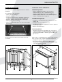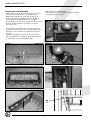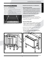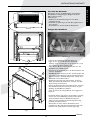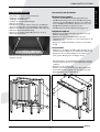
1
INSTALLATIEVOORSCHRIFT EN GEBRUIKERSHANDLEIDING
INSTRUCTIONS D’INSTALLATION ET MODE D’EMPLOI
INSTRUCTIONS FOR INSTALLATION AND OPERATIONS
INSTALLATIONSVORSCHRIFT UND GEBRAUCHSANWEISUNG
MAESTRO
Bewaar dit document zorgvuldig
Conservez soigneusement cette notice
Please retain this document carefully
Bewahren Sie dieses Dokument sorgfältig auf
DRU VERWARMING B.V.
HOLLAND
957.584.00
727
46
inw.ø101
ø12mm
781
39
486
600
805
800
440
5
38c-1098
min.70
Maestro
Belangrijk
• Zorg dat er minimaal 3 mtr afvoerpijp (verticaal) met een diameter van 101 mm
aangesloten wordt op het toestel.
• Voordat men het toestel in gebruik neemt dient u altijd de ruit schoon te maken, dit om
inbranden van evt. verontreinigingen tegen te gaan.
Important
• Assurez-vous de raccorder à l'appareil un conduit d'évacuation d'au moins 3 mètres de
haut et 101 mm de diamètre.
• Avant de mettre l'appareil en fonctionnement, il faut nettoyer soigneusement la vitre afin
d'éviter que des salissures puissent être carbonisées sur celle-ci.
Important
• Ensure that at least 3 m. (vertical) outlet pipe, 101 mm diameter, is connected to the
appliance.
• Before you start using your fire, it is wise to clean the glass front.This to prevent burning in
of possible dirt into the glass.
Wichtig
• Sorgen Sie dafür, daß minimal 3 Meter Abfuhrrohr (vertikal) mit einem Durchmesser von
101 mm an das Gerät angeschlossen wird.
• Bevor Sie das Gerät zum ersten Mal benützen sollten Sie das Glas reinigen. Dies um
einbrennen von eventueller Schmutz im Glas zu vermeiden.
Maestro
INHOUD
Woord vooraf . . . . . . . . . . . . . . . . . . . . . .
Uitpakken . . . . . . . . . . . . . . . . . . . . . . . . .
Aansluiten . . . . . . . . . . . . . . . . . . . . . . . . .
Belangrijk . . . . . . . . . . . . . . . . . . . . . . . . .
Installatievoorschrift . . . . . . . . . . . . . . . . .
Gassoort . . . . . . . . . . . . . . . . . . . . . . . . .
Belangrijk . . . . . . . . . . . . . . . . . . . . . . . . .
Plaatsbepaling . . . . . . . . . . . . . . . . . . . . . .
Aansluiting op het schoorsteenkanaal . . . .
Verwijderen mantel en glasraam . . . . . . . .
Aansluiting van de gastoevoer . . . . . . . . . .
Plaatsen van houtblokken . . . . . . . . . . . . .
Dit toestel is voorzien van een TTB . . . . .
Oorzaak werking van de TTB kan zijn . . . .
Maatregelen tegen het werken van de TTB
Uitvoering van de TTB . . . . . . . . . . . . . . .
Gebruikershandleiding . . . . . . . . . . . . . . .
.
.
.
.
.
.
.
.
.
.
.
.
.
.
.
.
.
.
.
.
.
.
.
.
.
.
.
.
.
.
.
.
.
.
.
.
.
.
.
.
.
.
.
.
.
.
.
.
.
.
.
.
.
.
.
.
.
.
.
.
.
.
.
.
.
.
.
.
.
.
.
.
.
.
.
.
.
.
.
.
.
.
.
.
.
.
.
.
.
.
.
.
.
.
.
.
.
.
.
.
.
.
.
.
.
.
.
.
.
.
.
.
.
.
.
.
.
.
.
Type Eurosit . . . . . . . . . . . . . . . . . . . . . . . . . . . . . . .4
In bedrijf stellen . . . . . . . . . . . . . . . . . . . . . . . . . . . .4
Buiten bedrijf stellen . . . . . . . . . . . . . . . . . . . . . . . . .4
Algemene opmerkingen . . . . . . . . . . . . . . . . . . . . . .5
Onderhoud en reiniging . . . . . . . . . . . . . . . . . . . . . .5
Verkleuring van wanden en plafonds . . . . . . . . . . . . .5
Eerste maal stoken . . . . . . . . . . . . . . . . . . . . . . . . . .6
Extra bescherming . . . . . . . . . . . . . . . . . . . . . . . . . .6
Afdanken . . . . . . . . . . . . . . . . . . . . . . . . . . . . . . . . .6
Garantie . . . . . . . . . . . . . . . . . . . . . . . . . . . . . . . . . .6
Ombouwinstructies . . . . . . . . . . . . . . . . . . . . . . . . .7
Verwisselen van de onderdelen . . . . . . . . . . . . . . . . .7
Waakvlamspuitstuk . . . . . . . . . . . . . . . . . . . . . . . . . .7
Hoofdbranderspuitstuk . . . . . . . . . . . . . . . . . . . . . . .7
Kleinstelspuitstuk . . . . . . . . . . . . . . . . . . . . . . . . . . .7
Instellen van de branderdruk . . . . . . . . . . . . . . . . . .8
Technische gegevens . . . . . . . . . . . . . . . . . . . . . . . .35
.2
.2
.2
.2
.2
.2
.2
.2
.2
.2
.3
.3
.4
.4
.4
.4
.4
GARANTIEBEWIJS
Wilt u dit garantiebewijs volledig invullen en samen met de rekening bij uw toestel bewaren.
Invullen in blokletters s.v.p.
Type: . . . . . . . . . . . . . . . . . . . . . . . . . . . . . . . . .
Kleur: . . . . . . . . . . . . . . . . . . . . . . . . . . . . . . . . .
Aankoopdatum: . . . . . . . . . . . . . . . . . . . . . . . . . .
Serienummer (op typeplaat): . . . . . . . . . . . . . . . .
Koper:
Naam . . .
Adres . . .
Postcode
Plaats . . .
Leverancier:
Naam . . . .
Adres . . . .
Postcode . .
Plaats . . . . .
.
.
.
.
.
.
.
.
.
.
.
.
.
.
.
.
.
.
.
.
.
.
.
.
.
.
.
.
.
.
.
.
.
.
.
.
.
.
.
.
.
.
.
.
.
.
.
.
.
.
.
.
.
.
.
.
.
.
.
.
.
.
.
.
.
.
.
.
.
.
.
.
.
.
.
.
.
.
.
.
.
.
.
.
.
.
.
.
.
.
.
.
.
.
.
.
.
.
.
.
.
.
.
.
.
.
.
.
.
.
.
.
.
.
.
.
.
.
.
.
.
.
.
.
.
.
.
.
.
.
.
.
.
.
.
.
.
.
.
.
.
.
.
.
.
.
.
.
.
.
.
.
.
.
.
.
.
.
.
.
.
.
.
.
.
.
.
.
.
.
.
.
.
.
.
.
.
.
.
.
.
.
.
.
.
.
.
.
.
.
.
.
.
.
.
.
.
.
.
.
.
.
.
.
.
.
.
.
.
.
.
.
.
.
.
.
.
.
.
.
.
.
.
.
.
.
.
.
.
.
.
.
.
.
.
.
DRU Verwarming garandeert de goede werking van dit apparaat bij vakkundige installatie
en gebruik volgens de gebruiksaanwijzingen.
IN GEVAL VAN STORINGEN, DIENT U ZICH ALTIJD TOT UW LEVERANCIER TE WENDEN.
Garantiebepalingen
• DRU Verwarming B.V. garandeert de goede werking van het toestel en staat er voor in dat het toestel met de grootste zorg is vervaardigd van deugdelijk
materiaal.
• De garantie geldt gedurende 1 jaar na datum van aankoop.
• Onder de garantie vallen alle gebreken, die een gevolg zijn van fouten in de constructie of voor de constructie gebruikte onderdelen.
• DRU Verwarming verplicht zich gedurende de garantieperiode gratis vervangende onderdelen te leveren. Het eerste jaar van de garantietermijn zullen - dit
ter beoordeling van DRU Verwarming B.V. - geen kosten in rekening worden gebracht.
• De garantie vervalt als storingen het gevolg zijn van foutieve installatie, van verkeerd gebruik of onderhoud van onderdelenvervanging door andere dan
originele onderdelen of van plaatsing of reparaties door onbevoegden.
• Indien het opsturen van het apparaat naar de fabriek noodzakelijk is dient dit franco te gebeuren. Het garantiebewijs s.v.p. meesturen.
• Wanneer u aanspraak wilt maken op fabrieksgarantie, wilt u dan eerst contact opnemen met uw installateur.
• Wilt u bij uw garantiebewijs ook de rekening van uw leverancier bewaren. Bij serviceverlening zal men hier naar vragen.
DRU Verwarming B.V.
Maestro
1
N e d e r l a n d s
INHOUD
INSTALLATIEVOORSCHRIFT
• Let op! Aanraking van hete delen kan brandblaren
veroorzaken!
• Het toestel dient door een erkend installateur
geïnstalleerd te worden (in België volgens NBN D 51-003).
• Het plaatsen van een z.g. stoffilter op of onder de mantel
is niet toegestaan.
• Natte kleding, handdoeken e.d. niet op de kachel te
drogen hangen!
Woord vooraf
Geachte klant,
Vriendelijk bedankt voor de aankoop van dit DRU
product. Onze producten zijn ontwikkeld en gefabriceerd
volgens de hoogst mogelijke kwaliteits-, prestatie- en
veiligheidseisen. Hierdoor kunt u rekenen op jarenlang
probleemloos gebruiksplezier.
Plaatsbepaling
• Het toestel mag alleen geplaatst worden in een goed
geventileerde ruimte, zodat er altijd voldoende
luchttoevoer is.
• Het toestel mag niet geplaatst worden tegen een wand
van brandbaar materiaal tenzij deze door een isolatieplaat
is beschermd.
• Houd de verbinding tussen pijpmond en schoorsteenkanaal zo kort en zo recht mogelijk. Het gasregelblok
moet goed bereikbaar zijn.
• De minimum afstand van de achterplaat tot de muur
bedraagt 70 mm.
In dit boekje vindt u instructies voor installatie en gebruik
van uw nieuwe toestel. Lees de instructies en
gebruikershandleiding goed door, zodat u zich vertrouwd
maakt met het toestel.Wilt u meer ondersteuning, neem
dan contact op met uw leverancier.
Uitpakken
Wanneer u klaar bent met uitpakken, dient de verpakking
via de reguliere weg te worden afgevoerd.
Aansluiten
Dit toestel dient te worden aangesloten door een bevoegd
installateur.
Aansluiting op het schoorsteenkanaal
• Laat eerst het schoorsteenkanaal vakkundig reinigen
alvorens het toestel hierop aan te sluiten. Hoewel het
toestel kan werken met een zeer kleine schoorsteentrek
adviseren wij een jaarlijkse controle van de schoorsteen
op eventuele verstoppingen e.d.
• De inwendige diameter van de pijpmond is 101 mm.
• De hoogte van de pijpmond is 600 mm.
• Gebruik voor de verbinding pijpmond-schoorsteenkanaal
corrosievast materiaal.
• Deze verbindingspijp mag nooit lager geplaatst worden
dan de pijpmond van de kachel.
• Leg een langere verbindingspijp van de pijpmond naar het
schoorsteenkanaal onder afschot (2%) in de richting van
de pijpmond.
Belangrijk
• Zorg dat er minimaal 3 mtr afvoerpijp (verticaal) met een
diameter van 101 mm aangesloten wordt op het toestel.
• Voordat men het toestel in gebruik neemt dient u altijd de
ruit schoon te maken, dit om inbranden van evt.
verontreinigingen tegen te gaan.
INSTALLATIEVOORSCHRIFT
Gassoort
Dit toestel is zonder aanpassing zowel geschikt voor
aardgas G20 als voor aardgas G25. Controleer of de
gassoort en de gasdruk ter plaatse overeenkomen met de
vermelding op het typeplaatje. Dit type plaatje bevindt zich
aan de onderkant van het toestel, onder de branderplaat.
Houdt u aan de gasinstallatievoorschriften en eventuele
plaatselijke voorschriften. Het toestel dient door een
bevoegd installateur te worden aangesloten.
Verwijderen mantel en glasraam
(figuur 2 en figuur 3)
Verwijderen mantel
• Neem het rooster (1) van de mantel.
• Draai de twee vleugelmoeren (2) aan de achterzijde los en
verwijder ze.
• De mantel hangt over de flens (3) van de zwarte toog.
Neem de mantel van het toestel door deze iets omhoog
te tillen en vervolgens naar voren te halen.
Om het toestel te laten werken op propaan (G31) dient
het omgebouwd te worden door een bevoegd installateur.
Een ombouwset is via hem te bestellen.
Belangrijk
Verwijderen glasraam
• Het glasraam uitnemen door de glasstrip (4) boven te
verwijderen. Deze is gemonteerd met 4 parkers (5).
• Zorg ervoor dat evt. overgordijnen of andere brandbare
materialen minstens 50 cm van het toestel verwijderd zijn.
2
INSTALLATIEVOORSCHRIFT
1
Gebruik in de toevoerleiding een gekeurde aansluitkraan
met koppeling (voor België moet deze B.G.V. gekeurd
zijn).Verder geldt:
• Ontlucht de toevoerleiding voordat het toestel wordt
vastgekoppeld.
• Vermijd spanningen op het gasregelblok en de leidingen.
• Controleer de aansluitingen op gasdichtheid.
3
Plaatsen van de houtblokken
Maestro fig. 4
Plaats de houtblokken als volgt:
• Leg het grote blok tegen de achterwand.
Let op !!!! Het is belangrijk dat het blok geheel tegen de
achterwand ligt.
• Vul de brander met vermiculiet (dit zit in het plastic zakje
bij de houtblokkenset).
• Verdeel het gelijkmatig over de branderbak en de bak er
omheen.
• G20/G25 (aardgas): Verdeel bovenop het vermiculiet op
de brander de zakjes bruine embers, zwarte en gele chips.
Dit geeft een gloeieffect op het branderbed.
• Bij G31 (propaan) mag men geen embers en chips
verdelen bovenop het vermiculiet op de brander, omdat
dan roetvorming kan ontstaan.
• Let op dat er geen vermiculiet op of tussen de
waakvlambrander komt, dit kan de goede werking van de
waakvlam verstoren.
• Plaats vervolgens de overige blokken zoals in fig. 4 is
aangegeven.
De blokken mogen niet op een andere manier neergelegd
worden, omdat dan roetvorming kan ontstaan, ook mogen
de blokken niet tegen de waakvlam brander aan liggen.
38C-1107
2
fig. 2
3
4
5
U kunt met het vlambeeld "spelen" door het vermiculiet,
embers en de chips op het brandbed te verplaatsen. Dit
kunt u net zo lang doen totdat naar uw wens een mooi
vlambeeld onstaan is.
38C-1108
Gebruik geen andere materialen dan die meegeleverd zijn.
Er mag niets op het branderbed worden gegooid, ook
geen afval, uitsluitend de voorgeschreven materialen met
de houtblokkenset.
De meegeleverde materialen zijn onbrandbaar en speciaal
voor dit toestel gemaakt.
fig. 3
Maestro
3
N e d e r l a n d s
Aansluiting van de gastoevoer
INSTALLATIEVOORSCHRIFT
GEBRUIKERSHANDLEIDING
Dit toestel is voorzien van een TTB
GEBRUIKERSHANDLEIDING
De TTB is een Thermische Terugslag Beveiliging die
reageert op het terugstromen van verbrandingsgassen
via de trekonderbreker van het toestel in de woonkamer.
Bij terugslag van verbrandingsgassen wordt het thermokoppel onderbroken door de TTB, waardoor de gastoevoer naar de branders afgesloten wordt.
Met deze beveiliging wordt voorkomen dat verbrandingsgassen voor langere tijd de woning instromen. De veiligheid reset zich na enkele minuten vanzelf en het toestel
kan opnieuw ontstoken worden.
Type EUROSIT
Het regelblok EUROSIT is voorzien van de volgende
bedieningsorganen:
* Draaiknop met volgende standen (1):
• gesloten stand ( )
• aansteek- en waakvlam stand ( )
• thermostaatstand
* druktoets (2) voor het bedienen van de piezo ( )
* handbediende regeling (3) met de volgende standen:
Oorzaak werking van de TTB kan zijn:
• Er is totaal geen of te weinig toevoer van verse lucht in de
woning (alle kieren afgedicht en ventilatie-openingen
afgesloten).
• De doorlaat van het schoorsteenkanaal is geheel of
gedeeltelijk geblokkeerd.
• De schoorsteenuitmonding is niet juist uitgevoerd,
waardoor valwinden in het schoorsteenkanaal kunnen
ontstaan.
• vol open
regelbaar tussen de minimum stand en maximum
stand van de handbediende gaskraan.
• uit
In bedrijf stellen
Om de waakvlam te ontsteken dient u de bedieningsknop
(1) op stand ( ) te draaien en volledig in te drukken.
Druk één of meerdere malen op knop (2) tot dat de
waakvlam brandt.Wanneer de waakvlam brandt, moet
knop 1 nog ongeveer 10 seconden ingedrukt blijven. Na het
loslaten van de knop moet de waakvlam blijven branden.
Indien dit niet gebeurt, dan dient bovenstaande herhaald te
worden en moet de knop langer ingedrukt gehouden
worden. Indien de ingestelde temperatuur hoger is dan de
kamertemperatuur, dan zal de hoofdbrander ontsteken
wanneer de knop wordt losgelaten.
Met behulp van de thermostaatknop (1) wordt de
gewenste temperatuur ingesteld.
Maatregelen tegen het werken van de TTB
Na afkoeling van de TTB kan het toestel opnieuw worden
ontstoken.
Indien de beveiliging opnieuw in werking treed kan er een
raam of luchttoevoer opening geopend worden.
Wordt met deze handeling de storing opgeheven, dan
betekent dit dat de woning hermetisch dicht is en het
toestel zijn verbrandingsgassen niet via de schoorsteen kan
afvoeren. Er zal een luchttoevoeropening in de woning
moeten worden aangebracht of open gehouden.
Blijft de beveiliging na deze handelingen nog werken, dan
dienen de eerder genoemde andere mogelijke oorzaken te
worden onderzocht en opgeheven.
De beveiliging mag niet buiten werking worden gesteld.
Opgelet:
Wanneer de thermostaat warmte vraagt zal deze voorrang
hebben t.o.v. de ingestelde waarde van de handbediende
regeling.
Wanneer alleen met de handbediende regeling gewerkt
wordt, plaats dan de thermostatische knop op zijn laagste
stand.
Wanneer de thermostatische knop op de stand ( )staat
dan blijft alleen de waakvlam branden en wordt noch de
thermostatische kraan noch de handbediende kraan in
werking gesteld.
Uitvoering van de TTB
De TTB beveiliging is van enkele speciale componenten
voorzien die bij eventuele vervanging ook weer toegepast
dienen te worden.
Het aanbrengen van een "standaard" thermokoppel wordt
ten zeerste afgeraden.
Buiten bedrijf stellen
Voor het doven van het toestel draait men knop 1 op
stand . Hierdoor worden zowel de waakvlam als
hoofdbrander gedoofd.
Op de waakvlamstand ( ) blijft alleen de waakvlam
branden.
4
ALGEMENE OPMERKINGEN
waarna deze met een steeksleutel een kwartslag
aangedraaid moet worden.
1.Thermostaatknop + drukknop voor toevoer waakvlam
Verkleuring van wanden en plafonds
Bruinverkleuring is een vervelend probleem en is moeilijk
op te lossen. Bruinverkleuring kan worden veroorzaakt
door onder andere stofverbranding veroorzaakt door te
weinig ventilatie, door het roken van sigaretten of het
branden van kaarsen.
2. Piezo
3. Handbediende regeling
1.
Deze problemen kunnen worden voorkomen door:
Het vertrek waar het toestel zich bevind goed te
ventileren. Een goede richtlijn hiervoor is:
Bij nieuwbouw
Bij bestaande bouw
.
.
.
.
.
.
.
.
.
.
.
.
.
.
.
.
.
.
.
.
.
.
.
.
.
.
.
.
.
.
.
.
.
.
.
.
.
.
.
.
.
.
.
.
.
.
.
.
.
.
.
.
.
.
.
.
.
.
.
.
.
.
.
.
.
.
.
.
.
.
.
.
.
.
.
.
.
.
.
.
.
.
.
.
.
.
.
.
.
.
.
.
.
.
.
.
.
.
.
.
.....................
.....................
.
.
.
.
.
.
.
.
.
.
.
.
.
.
.
.
.
.
.
.
.
.
.
.
.
.
.
.
.
.
.
.
.
.
.
.
.
.
.
.
.
.
.
.
.
.
.
.
.
.
.
.
.
.
.
.
.
.
.
.
.
.
.
.
.
.
.
.
.
.
.
.
.
.
.
.
.
.
.
.
.
.
.
.
.
.
.
.
.
.
.
.
.
.
.
.
.
.
.
.
.
.
.
.
.
.
.
.
.
.
.
.
.
.
.
.
.
.
.
.
.
.
.
.
.
.
.
.
.
.
.
.
.
.
.
.
.
.
.
.
.
.
.
.
.
.
.
.
.
.
.
.
.
.
.
.
.
.
.
.
.
.
.
.
.
Hartelijk dank voor uw medewerking.
✂
Let op: Bij het vervangen van het thermoelement moet
de wartel in het gasregelblok handvast gedraaid worden,
.
.
.
.
.
De schoorsteen moet regelmatig worden
gecontroleerd,om zeker te stellen dat alle rookgassen via
de schoorsteen
worden afgevoerd. Er op toezien en voorkomen dat er
overmatige roetopbouw plaatsvindt in de schoorsteen. Het
roet dat zich vormt moet worden verwijderd, uitsluitend in
koude toestand met een borstel of stofzuiger. De ventilatie
moet regelmatig worden gecontroleerd, om zeker te zijn
dat er geen belemmeringen zijn.
Aankoopdatum: . . . . . . . . . .
Serienummer (op typeplaat):
Detaillist/installateur:
Naam . . . . . . . . . . . . . . . . . .
Adres . . . . . . . . . . . . . . . . . .
Postcode . . . . . . . . . . . . . . .
Plaats . . . . . . . . . . . . . . . . . .
Telefoon . . . . . . . . . . . . . . . .
Uw toestel dient eenmaal per jaar door een gekwalificeerd
bedrijf te worden gecontroleerd, en waar nodig, hersteld
of gereinigd. De controle en het onderhoud dient in ieder
geval een goede en veilige werking van het toestel te
omvatten. U kunt hiervoor gebruik maken van uw
gasinstallateur of een gespecialiseerd onderhoudsbedrijf.
Het verdient aanbeveling om vóór en tijdens het
stookseizoen het toestel enkele malen stofvrij te maken.
Op de binnenkant van het glasraam kan zich na verloop
van tijd aanslag vormen U kunt deze verwijderen met een
vochtige doek of met een nietkrassend reinigingsmiddel
(zoals koperpoets). Doe dit zodra aanslag verschijnt, zodat
deze niet kan inbranden en reinigen onmogelijk wordt. Bij
het reinigen van de mantel geen bijtende of schurende
middelen gebruiken. Lakbeschadigingen, bijvoorbeeld door
het plaatsen van voorwerpen op of tegen de mantel, vallen
buiten de garantie.
DRU Verwarming kan alleen garantie verlenen indien deze registratiekaart volledig en duidelijk
in blokletters en binnen 8 dagen opgestuurd is aan DRU Verwarming B.V.
Onderhoud en reiniging
Maak zo weinig mogelijk gebruik van kaarsen en
olielampjes en houd het verbrandingslontje zo kort
mogelijk. Deze "sfeerbrengers" zorgen voor aanzienlijke
hoeveelheden vervuilde en ongezonde roetdeeltjes in uw
woning. Rook van sigaretten en sigaren bevat o.a.
teerstoffen die bij verhitting eveneens op koudere en
vochtige muren zullen neerslaan. Bij een nieuw gemetselde
REGISTRATIEKAART
ALGEMENE OPMERKINGEN
: 3.24 m3 / uur per m2
vloeroppervlak van een vertrek.
: 25.20 m3 / uur voor een
vertrek.
.................................
.................................
2.
Type: . . .
Kleur: . .
Koper:
Naam . .
Adres . .
Postcode
Plaats . . .
Telefoon
3.
N e d e r l a n d s
Gelieve na het doven van het toestel 5 minuten te
wachten alvorens het toestel opnieuw te ontsteken.
ALGEMENE OPMERKINGEN
OMBOUWINSTRUCTIES
schouw of na een verbouwing wordt aanbevolen minimaal
6 weken te wachten voordat men gaat stoken, het
bouwvocht moet namelijk geheel verdwenen zijn uit
wanden, vloer en plafond.
Eerste maal stoken
Garantie
De REGISTRATIEKAART gelieve binnen 5 dagen na
aankoop in te vullen en op te sturen in een envelop naar
het onderstaande adres.
DRU VERWARMING B.V.
Tijdens de eerste maal stoken kan er een onaangename
geur ontstaan, die wordt veroorzaakt door het uitdampen
van de lak. Dit verdwijnt na enkele uren. Daarom raden wij
u aan het toestel de eerste maal op de hoogste stand te
stoken terwijl u tevens het vertrek waarin de kachel staat
goed ventileert.
Extra bescherming
Indien het toestel in een vertrek geïnstalleerd wordt waar
jonge kinderen of hulpbehoevende mensen zonder toezicht
verblijven, is het wenselijk het toestel af te schermen.
Afdanken
Indien u het toestel vervangt of verwijdert, moet u het
toestel via de reguliere weg afvoeren.Voordat tot
demontage wordt overgegaan eerst de aansluitkraan met
koppeling dichtdraaien. De koppeling tussen aansluitkraan
en toestel losdraaien. Het gehele toestel kan nu worden
gedemonteerd en afgevoerd.
VERSTUREN IN EEN
ENVELOP
DRU VERWARMING B.V.
ANTWOORDNUMMER 4551
6920 ZX DUIVEN
✂
ANTWOORDNUMMER 4551
6920 ZX DUIVEN
Het GARANTIEBEWIJS (blz. 1) kunt u zelf behouden.
De garantie gaat in op het ogenblik, dat de volledig
ingevulde registratiekaart door DRU Verwarming is
ontvangen.
VOOR BELGIË DE KAART INVULLEN OP PAGINA 13 EN 14
EN STUREN AAN DRU BELGIUM.
OMBOUWINSTRUCTIES
Verwisselen van de onderdelen:
De ombouw moet worden uitgevoerd door een erkende
installateur.
Waakvlamspuitstuk
Draai de waakvlamwartel (E) aan het eind van de
waakvlamleiding los, trek de waakvlamleiding met
tonnetje uit de waakvlambrander en verwijder het
waakvlamspuitstuk. Plaats het nieuwe waakvlamspuitstuk
en draai de waakvlamwartel stevig aan.
Voor aanvang van het ombouwen:
• Sluit de gastoevoerleiding af.
• Verwijder het front.
• Het glasraam uitnemen door de glasstrip (4) boven te
verwijderen. Deze is gemonteerd met 4 parkers (5).
• Verwijder de bakjes vermiculiet links en rechts (A).
• Ontkoppel de gastoevoerleiding.
• Neem de afdekkap (B) weg door de twee bouten (C) te
demonteren.
A
Hoofdbranderspuitstuk
• Verwijder de branderbak (F). Deze is gemonteerd met 4
parkers (G).
• Verwijder met een steeksleutel de twee
hoofdbranderspuitstukken (H) links en rechts en plaats de
nieuwe spuitstukken.
• Plaats de branderbak terug.
A
Kleinstelspuitstuk
Verwijder de kap van het gasregelblok door schroef (I) los
te draaien.Verwijder nu het kleinstelspuitstuk (J). Plaats het
nieuwe klein-stelspuitstuk en draai het goed vast. Breng de
kap weer aan.
Nu kan begonnen worden met het verwisselen van de
onderdelen:
Opm.: Indien u de waakvlambrander niet goed kunt bereiken,
kunt u vervolgens de complete branderunit verwijderen.
• Verwijder de 3 parkers (D).
• Neem de branderunit uit het toestel. Behandel de
branderunit met zorg, omdat het geheel nogal gevoelig is
i.v.m. de lange gastoevoerbuis.
3
C
4
5
B
D
38C-1108
38C-1109
Maestro
7
N e d e r l a n d s
OMBOUW INSTRUCTIES
OMBOUWINSTRUCTIES
Instellen van de branderdruk
Koppel, indien nodig, de gastoevoer-leiding weer aan het
toestel en open de gastoevoer van het nieuwe gas.
Ontsteek de waakvlam en zet de thermostaat op de
hoogste stand. Het gasregelblok heeft twee drukmeetpunten, waarmee de branderdruk en de voordruk,
eenvoudig met een manometer gecontroleerd kan worden.
Draai de drukmeetpuntschroeven (K) los en sluit de
manometers aan.
Plak tenslotte de nieuwe typeplaat.
Sluit de kabels weer aan en plaats vervolgens de bakjes
vermiculiet, glasraam en front.
I
Voor ombouw naar propaan moet de branderdruk met
de drukregel-schroef (L) worden ingesteld volgens tabel.
Controleer of de voordruk overeenkomt met de tabel
(pag. 35).
Indien u de branderunit uit het toestel genomen heeft,
deze terug plaatsen. Let daarbij op dat de branderplaat in
de rail (M) van de verbrandingskamer glijdt.
J
E
L
K
G
F
M
H
8
TABLE DES MATIÈRES
Introduction . . . . . . . . . . . . . . . . . . . . . . . .
Déballage de l’appareil . . . . . . . . . . . . . . . .
Branchement . . . . . . . . . . . . . . . . . . . . . . .
Important . . . . . . . . . . . . . . . . . . . . . . . . . .
Instructions d’ installation . . . . . . . . . . . . . .
Sorte de gaz . . . . . . . . . . . . . . . . . . . . . . . .
Important . . . . . . . . . . . . . . . . . . . . . . . . . .
Emplacement . . . . . . . . . . . . . . . . . . . . . . .
Raccordement au canal de la cheminee . . .
Retirer le manteau et la vitre . . . . . . . . . . .
Raccordement à la conduite de gaz . . . . . .
Généralités. . . . . . . . . . . . . . . . . . . . . . . . .
Pose des bûches . . . . . . . . . . . . . . . . . . . . .
L’appareil est prévu d’une PRT . . . . . . . . . .
Causes de la mise en marche de la PRT . . .
Mesures à prendre après le fonctionnement
de la PRT . . . . . . . . . . . . . . . . . . . . . . . . . .
.
.
.
.
.
.
.
.
.
.
.
.
.
.
.
.
.
.
.
.
.
.
.
.
.
.
.
.
.
.
.
.
.
.
.
.
.
.
.
.
.
.
.
.
.
.
.
.
.
.
.
.
.
.
.
.
.
.
.
.
.
.
.
.
.
.
.
.
.
.
.
.
.
.
.
Exécution de la PRT . . . . . . . . . . . . . . . . . . . . . .
Mode d’emploi . . . . . . . . . . . . . . . . . . . . . . . . . .
Type Eurosit . . . . . . . . . . . . . . . . . . . . . . . . . . . .
Allumage . . . . . . . . . . . . . . . . . . . . . . . . . . . . . . .
Extinction du foyer a gaz . . . . . . . . . . . . . . . . . . .
Remarques générales . . . . . . . . . . . . . . . . . . . . .
Entretien et nettoyage . . . . . . . . . . . . . . . . . . . .
Changement de couleur des murs et plafond . . .
La première mise en service . . . . . . . . . . . . . . . .
Protection supplémentaire . . . . . . . . . . . . . . . . .
Mise aux déchets . . . . . . . . . . . . . . . . . . . . . . . .
Garantie . . . . . . . . . . . . . . . . . . . . . . . . . . . . . . .
Instructions de conversion . . . . . . . . . . . . . . . . .
Replacement des pièces et composants . . . . . . .
Injecteur de la veilleuse . . . . . . . . . . . . . . . . . . . .
Injecteurs du brûleur principal . . . . . . . . . . . . . .
Injecteur à débit réduit . . . . . . . . . . . . . . . . . . . .
Réglage de la pression d’alimentation du brûleur
Détails techniques . . . . . . . . . . . . . . . . . . . . . . . .
.10
.10
.10
.10
.10
.10
.10
.10
.10
.10
.11
.11
.11
.12
.12
. . . . . .12
.
.
.
.
.
.
.
.
.
.
.
.
.
.
.
.
.
.
.
.12
.12
.12
.12
.13
.13
.13
.13
.14
.14
.14
.14
.15
.15
.15
.15
.15
.16
.35
GARANTIEBEWIJS
CERTIFICAT DE GARANTIE
Wilt u dit garantiebewijs volledig invullen en samen met de rekening bij uw toestel bewaren. Invullen in
blokletters s.v.p.
Veuillez remplir dûment ce bon de garantie et le conserver avec le bon d’achat près de votre appareil.
Ecrire en lettres majuscules s.v.p..
Type: . . . . . . . . . .
Koper / Acheteur:
Naam / Nom . . . .
Adres / Adresse . .
Plaats / Lieu . . . . .
Prov. . . . . . . . . . .
.......................
.
.
.
.
.
.
.
.
.
.
.
.
.
.
.
.
.
.
.
.
.
.
.
.
.
.
.
.
.
.
.
.
.
.
.
.
.
.
.
.
.
.
.
.
.
.
.
.
.
.
.
.
.
.
.
.
.
.
.
.
.
.
.
.
.
.
.
.
.
.
.
.
.
.
.
.
.
.
.
.
.
.
.
.
.
.
.
.
Datum van aankoop / Date d’achat:
Leverancier / Fournisseur:
Naam / Nom . . . . . . . . . . . . . . . . .
Adres / Adresse . . . . . . . . . . . . . . .
Plaats / Lieu . . . . . . . . . . . . . . . . . .
.
.
.
.
...........
...........
...........
...........
Garantiebepalingen DRU Belgium
garanderen ten volle gedurende één jaar na aankoop de goede werking van dit apparaat bij vakkundige installatie en gebruik volgens de aanwijzingen. Deze
garantie omvat alle gebreken, die hun oorzaak vinden in eventuele materiaalfouten. De aansprakelijkheid van DRU dekt het gratis leveren van nieuwe
onderdelen.Arbeidsloon en andere kosten kunnen echter niet aan DRU in rekening worden gebracht. De garantie vervalt bij verkeerd gebruik of
onderhoud, wanneer bij reparatie door derden andere dan originele onderdelen zijn gebruikt, bij gebruik of verkeerd ombouwen op een andere
gassoort dan waarvoor het apparaat in de fabriek is afgesteld, of bij reparaties door onbevoegden.Voor onderdelen die niet door DRU worden
vervaardigd, geldt de garantie die de fabrikant van deze onderdelen geeft. Indien het apparaaat naar Aartselaar moet worden opgezonden, dient dit
franco te geschieden. Klachten kunnen slechts in behandeling worden genomen, wanneer de betrokken leverancier/installateur of gasbedrijf de klacht
indient, onder gelijktijdige opzending van deze garantiekaart
Conditions de garantie DRU Belgium
garantissent entièrement pendant la durée d’un an après l’achat le bon fonctionnement de cet appareil, si l’installation à été faite de façon compétente et s’il
est utilisé suivant les prescriptions. Cette garantie englobe tous les défauts qui trouvent leur origine dans un vice de construction. La responsabilité de DRU
couvre la livraison gratuite de nouvelles pièces détachées. Des frais de main-d’oeuvre et autres ne peuvent cependant pas être portés en compte à DRU. La
garantie tombe en cas de mauvais usage ou d’entretien défectueux quand, lors de réparation par des tiers d’autres pièces détachées que celles d’origine ont
été employées, en cas d’usage ou de conversion erronée pour un autre genre de gaz, que celui pour lequel l’appareil a été reglé à l’usine, ou en cas de
réparations par des personnes non qualifiées. Pour des pièces détachées qui ne sont pas fabriquées par DRU, vaut la garantie donnée par le fabricant de ces
pièces. Si l’appareil doit être expédié à Aartselaar, ceci doit se faire franco. Des réclamations ne pourront être admises que si c’est le fournisseur installateur
ou la compagnie du gaz qui introduit la réclamation, en envoyant en même temps la présente carte de garantie.
Maestro
9
F r a n ç a i s
TABLE DES MATIÈRES
INSTRUCTIONS D’INSTALLATION
Introduction
Important
• Veillez à ce que les rideaux ou tout autre matériel
inflammable soient au moins à une distance de 50 cm de
l’appareil.
• Attention: vous pouvez vous brûler si vous touchez des
parties chaudes de l’appareil!
• L’appareil doit être installé et entretenu par un installateur
agréé, (au Belgique selon NBN D 51-003).
• Il est interdit d’installer ce qu’on appelle un filtre à
poussières sur ou en dessous du manteau.
• Ne mettez pas de vêtements, serviettes, etc. à sécher sur
le poêle.
Cher client,
Nous vous remercions d'avoir acheté cet article fabriqué
par DRU.Tous nos articles sont conçus et fabriqués dans
le respect des consignes les plus sévères de qualité, de
performance et de sécurité. Ainsi, vous êtes assuré de
profiter de votre achat pendant des années, sans aucun
problème.
Dans ce livret, vous trouverez des instructions pour
l'installation et l'utilisation de votre nouveau foyer.
Lisez avec attention toutes les instructions ainsi que le
manuel de l'utilisateur afin de vous familiariser avec cet
appareil. Pour toute assistance supplémentaire, veuillez
contacter votre fournisseur.
Emplacement
• L'appareil doit être installé uniquement dans un local bien
ventilé afin de garantir une amenée d'air suffisante.
• L’appareil ne peut pas être placé contre un mur composé
ou recouvert de matériaux inflammables, à moins que
celui-ci ne soit protégé par une plaque en matériau isolant.
• Gardez la connection entre le buselot d’évacuation du
foyer et le canal de la cheminée aussi courte et aussi
droite que possible. La vanne thermostatique de réglage
doit rester accessible.
• La distance minimum à respecter entre l’arrière de
l’appareil et le mur est de 70 mm.
Déballage de l’appareil
Après avoir déballé l’appareil, jetez l’emballage
conformément aux règles en vigueur.
Branchement
Cet appareil doit être branché par un installateur
compétent.
Important
Raccordement au canal de la cheminée
• Assurez-vous de raccorder à l'appareil un conduit
d'évacuation d'au moins 3 mètres de haut et 101 mm de
diamètre.
• Avant de mettre l'appareil en fonctionnement, il faut nettoyer
soigneusement la vitre afin d'éviter que des salissures puissent
être carbonisées sur celle-ci.
• Faites nettoyer soigneusement et dans les règles de l’art le
conduit de fumées avant d’y raccorder l’appareil. Bien que
celui-ci puisse fonctionner avec un petit tirage, nous vous
conseillons de faire procéder à un contrôle annuel de
votre cheminée afin de prévenir d’éventuelles obstructions
et autres problèmes
• Le diamètre intérieur de l'embouchure de tube est de 101
mm.
• La hauteur de l'embouchure du tuyau est 600 mm.
• Pour le raccordement de l'embouchure de tube au canal
de la cheminée, utilisez du materiel résistant à la
corrosion.
• Ce tuyau de raccord ne peut jamais être placé plus bas
que l'embouchure du tube du poêle.
• Placez un tube de raccordement plus long depuis
l'embouchure du tube vers le canal de la cheminée, avec
inclinaison (2%) en direction de l'embouchure du tube.
INSTRUCTIONS D’INSTALLATION
Sorte de gaz
Cet appareil peut être raccordé sans adaptation au gaz
naturel G20 comme G25.
Vérifiez que le type et la pression du gaz sur les lieux de
l'installation sont conformes aux informations figurant sur
la plaquette signalétique. Cette plaque signalétique se
trouve en dessous de l’appareil, sous la plaque du brûleur.
Respectez les consignes d'installation relatives au gaz ainsi
que toute prescription locale. L'appareil doit être branché
par un installateur compétent.
Retirer le manteau et la vitre (schémas 2 et 3)
Retirer le manteau
• Otez la grille (1) du manteau
• Dévissez complètement les deux écrous à ailettes (2) à
l’arrière
• Le manteau repose sur le bourrelet (3) de la coiffe noire à
l’arrière
Pour faire fonctionner l’appareil au gaz propane (G31), il
doit être converti par un installateur reconnu.Vous pouvez
commander un jeu de conversion par son biais.
10
INSTRUCTIONS D’INSTALLATION
Retirer la vitre
• Otez la vitre en retirant le profilé (4) fixé sur la partie
supérieure par 4 vis (5).
1
Raccordement à la conduite de gaz
Dans le conduit d'alimentation, utilisez un robinet d'arrêt
agréé avec raccord. (En Belgique, ce robinet doit être agréé
par B.G.V.-A.G.B.). Par ailleurs, respectez les consignes
suivantes :
• Faites le vide d'air du conduit d'alimentation avant de
brancher définitivement l'appareil.
• Évitez toute tension sur les conduits et sur le robinet de
commande.
• Vérifiez que les branchements ne laissent pas échapper de gaz.
3
Pose des bûches
38C-1107
2
fig. 2
Maestro fig. 4
Les bûches se placent comme suit:
• Placer la grosse bûche contre la paroi arrière sur.
Prenez garde! Il est très important que la bûche repose
entièrement contre la paroi arrière.
• Remplir le brûleur de vermiculite (contenue dans le sac
plastique fourni avec le jeu de bûches).
• La répartir de façon égale sur le bac du brûleur et autour.
• G20/G25 (gaz naturel): Répartir au-dessus de la vermiculite,
sur le brûleur, le petit sac de mâchefer brun, chips noir et
jaune (qui donne un effet incandescent au foyer).
• En cas de raccordement au G31 (propane), ne pas utiliser
de mâchefer ni de chips sur la vermiculite du brûleur pour
éviter la formation de suie.
• Veiller à ce que la vermiculite ne tombe pas sur ou au
milieu du brûleur de la veilleuse car cela pourrait entraver
le bon fonctionnement de celle-ci.
• Poser ensuite les autres bûches comme indiqué ci-contre
en faisant. Les bûches doivent être placées de la manière
indiquée, sinon de la suie peut se former. Les bûches ne
doivent pas non plus être posées contre la veilleuse, car
cela peut avoir un effet négatif sur le dispositif de
protection contre les gaz toxiques.
3
4
5
38C-1108
fig. 3
Maestro
11
F r a n ç a i s
Décrochez le manteau de l’appareil en le tirant vers vous
après l’avoir soulevé légèrement
INSTRUCTIONS D’INSTALLATION
MODE D’EMPLOI
Vous pouvez "jouer" avec les flammes en déplaçant la
vermiculite, le mâchefer et les chips sur le foyer. Bougez les
comme vous l’entendez pour obtenir le jeu de flammes qui
vous plaît.
Exécution de la PRT
La protection PRT est prévue de quelques composantes
spéciales qui, dans le cas d’un remplacement éventuel,
doivent être appliquées.
L’installation d’un couple électro-thermique « standard »
n’est pas permis.
L’appareil est prévu d’une PRT
But et fonctionnement
La PRT est une Protection Retour de flamme Thermique
qui réagit au reflux des gaz de combustion par le coupetirage de l’appareil dans la pièce.
En cas de reflux des gaz de combustion le couple électrothermique est interrompu par la PRT de sorte que la
distribution de gaz aux brûleurs est coupée.
Cette protection prévient l’afflux de gaz dans la maison. Le
blocage s’annulera automatiquement après quelques
minutes après quoi le feu pourra être allumé à nouveau.
MODE D’EMPLOI
Type Eurosit
Le bloc de sécurité EUROSIT contient les boutons de
commande suivants:
* Bouton tournant avec les positions suivantes (1):
• position extinction ( )
• position allumage et veilleuse ( )
• thermostat
* bouton poussoir (2) pour étincelle ( )
* robinet manuel (3)
contenant les positions suivantes:
Causes de la mise en marche de la PRT
Il n’y a aucun apport d’air frais dans la maison (toutes les
fentes sont bouchées et toutes les ouvertures de
ventilation sont fermées).
Il y a insuffisamment de ventilation dans la maison ce qui
est encore renforcé par la mise en marche d’un appareil
d’extraction d’air mécanique (p.ex. une hotte !). Ainsi les
gaz brûlés sont aspirés dans la maison.
L’ouverture du tuyau de canalisation de la cheminée est
totalement ou partiellement bloqué.
Le débouché de la cheminée n’est pas exécuté
correctement de sorte que des rafales de vent peuvent
pénétrer dans la cheminée.
S’il y a des fuites dans la connection foyer-cheminée, de
faux tirages peuvent se former qui ont une influence
négative sur le tirage de la cheminée.
• débit maximal
réglage entre débit réduit et débit maximum du
robinet manuel
• éteint
Allumage
Pour allumer la veilleuse, tourner le bouton (1) de
commande en position d’allumage ( ) et appuyer le
bouton à fond. Appuyer simultanément et à plusieurs
reprises si nécessaire sur le bouton (2) jusqu’à l’allumage
de la veilleuse. Quand la veilleuse brûle, il faut encore
maintenir le bouton 1 enfoncé pendant 10 secondes.
Ensuite, en lâchant le bouton, la veilleuse doit fonctionner
normalement.
Si la veilleuse s’éteint, il faut recommencer l’opération et
maintenir le bouton enfoncé plus longtemps. Si la
température demandée est plus élevée que la température
ambiante, le brûleur principal s’allumera en lâchant le
bouton.
Mesures à prendre après le fonctionnement
de la PRT
Après le refroidissement de la PRT, l’appareil peut être
rallumé à nouveau.
Si la protection se met de nouveau en marche, une fenêtre
ou ouverture de ventilation peut être ouverte.
Si, en faisant cela, l’interruption se termine, cela signifie que
la maison est hermétiquement étanche et que l’appareil ne
peut pas faire s’écouler les gaz brûlés par la cheminée. Une
ouverture d’apport d’air devra être faite dans la maison ou
devra être tenue ouverte.
Si, après tous ces actions, la protection se met toujours en
marche, d’autres causes éventuelles, comme mentionnées
dans le paragraphe précédent, doivent être contrôlées et
être éliminées.
La protection ne peut jamais être mise hors service.
A l’aide du bouton du thermostat (1), on peut régler la
température désirée.
Important :
Lorsque le thermostat est demandeur de chaleur, il aura
la priorité sur l’allure établie à l’aide de la vanne manuelle.
Afin de ne travailler qu’avec la vanne manuelle, il faut
régler le bouton thermostatique sur sa position de
12
REMARQUES GÉNÉRALES
Extinction du foyer a gaz
Pour l’extinction de l’appareil, il suffit de tourner le
bouton 1 sur la position . Le brûleur ainsi que la
veilleuse sont éteints.
Sur la position veilleuse ( ), seule la veilleuse reste
allumée.
détergent ou abrasif pour nettoyer le manteau. Les dégâts
causés à la laque, par des objets posés sur ou contre le
manteau notamment, sont exclus de la garantie.
Le conduit de cheminée doit être régulièrement contrôlé
pour s’assurer que tous les gaz de combustion s’évacuent
bien par ce conduit.Vérifier et prévenir un dépôt excessif
de suie dans le conduit de cheminée. La suie qui s’est
déposée doit être nettoyée. Ne ramoner que lorsque la
cheminée est froide, au moyen d’une brosse ou d’un
aspirateur. La ventilation doit être régulièrement contrôlée
pour vérifier qu’il n’y a pas d’obstructions.
F r a n ç a i s
fonctionnement la plus basse.
Lorsque le bouton thermostatique se trouve en position
( ), seule la veilleuse est encore allumée et ni la vanne
thermostatique, ni la vanne manuelle ne peuvent être
actionnées.
Attention : lors du remplacement du thermocouple, il
faut d’abord visser manuellement l’écrou du thermocouple
dans le bloc gaz, pour ensuite le serrer d’un quart de tour
à l’aide d’une clé appropriée.
Il est nécessaire après l’extinction du foyer à gaz
d’attendre au moins 5 minutes avant de réallumer
l’appareil.
1. Boulon du thermostat + bouton pousson pour allumage
veilleuse
2. Piezo
3. Robinet manuel
Changement de couleur des murs et plafonds
La teinte marron que prennent les murs et plafonds est un
véritable problème qui est difficile à résoudre. Cette
pellicule marron peut notamment provenir de la
combustion des matériaux, d’un manque de ventilation, de
la fumée de cigarettes ou de bougies.
...........
...........
...........
...........
.
.
.
.
.
.
.
.
.
.
.
.
.
.
.
.
.
.
.
.
.
.
.
.
.
.
.
.
.
.
.
.
.
.
.
.
.
.
.
.
.
.
.
.
.
.
.
.
.
.
.
.
.
.
.
.
.
.
.
.
.
.
.
.
.
.
.
.
.
.
.
.
.
.
.
.
.
.
.
.
.
.
.
.
.
.
.
.
.
.
.
.
.
.
.
.
.
.
.
.
.
.
.
.
.
.
.
.
.
.
.
.
.
.
.
.
.
.
.
.
.
.
.
.
Datum van aankoop / Date d’achat:
Leverancier / Fournisseur:
Naam / Nom . . . . . . . . . . . . . . . . .
Adres / Adresse . . . . . . . . . . . . . . .
Plaats / Lieu . . . . . . . . . . . . . . . . . .
DRU BELGIUM
✂
Votre appareil doit être contrôlé chaque année par une
entreprise qualifiée. Le contrôle et l’entretien doivent
dans tous les cas déboucher sur un fonctionnement
correct et sans risque de l’appareil. Vous pouvez pour cela
faire appel à votre gazinstallateur ou à une société
d’entretien spécialisée. Il est grandement conseillé de
dépoussiérer l’appareil plusieurs fois avant et pendant la
saison froide. Au bout d’un certain temps, du dépôt peut
apparaître sur la face intérieure de la vitre. Pour nettoyer,
utilisez un chiffon humide ou un produit d’entretien non
abrasif (pour cheminée). Procédez au nettoyage dés que
vous voyez du dépôt pour éviter que la salissure ne cuise
et ne puisse plus disparaître. N’utilisez pas de produit
...............................
Entretien et nettoyage
Type: . . . . . . . . . .
Koper / Acheteur:
Naam / Nom . . . .
Adres / Adresse . .
Plaats / Lieu . . . . .
Prov. . . . . . . . . . .
REMARQUES GÉNÉRALES
Ce certificat de garantie ne devient valable que si la carte d’enregistrement ci-jointe
complètement remplie est envoyée à DRU Belgium dans les 5 jours après l’achat. Priére de
compléter en carectères d’imprimerie.
2.
REGISTRATIEKAART
CARTE D’ENREGISTREMENT
3.
Dit garantiebewijs verkrijgt slechts geldigheid indien de bijbehorende registratiekaart volledig
ingevuld en binnen 5 dagen na aankoop naar DRU Belgium wordt opgezonden. A.u.b. in
blokletters invullen.
1.
REMARQUES GÉNÉRALES
Ce problème peut être évité en ventilant suffisamment la
pièce où l’appareil se trouve. La règle à respecter est la
suivante :
Pour les nouvelles constructions : 3.24 m3 / heure par m2
de surface au sol dans
la pièce
Pour les constructions existantes : 25.20 m3 / heure pour
la pièce.
Il est recommandé d’utiliser le moins souvent possible des
bougies et des lampes à huile et, si c’est le cas, la mèche
devrait être la plus courte possible. Ces "éléments
d’ambiance" sont à l’origine de quantités considérables de
particules de suie salissantes et malsaines dans votre
logement. La fumée de cigarettes et cigares contient
notamment des particules de goudron qui, réchauffées, se
déposent sur les murs frais et humides. Au cas où le
manteau de cheminée vient d’être fait ou après des
travaux de modification, il est conseillé d’attendre au
moins 6 semaines pour chauffer jusqu’à ce que l’humidité
de la construction disparaisse complètement des murs, du
sol et du plafond.
La première mise en service
Lors de la première mise en service, l’évaporation de la
laque peut provoquer une odeur désagréable. Cette odeur
disparaîtra après quelques heures. Nous vous conseillons de
chauffer la première fois l’appareil au maximum en prenant
soin de bien aérer la pièce où la cheminée est installée.
Protection supplémentaire
Si l’appareil est installé dans une pièce dans laquelle
peuvent séjourner de petits enfants ou des personnes
moins valides sans surveillance, il est préférable de prévoir
une grille autour de l’appareil.
Mise aux déchets
Si vous remplacez ou enlevez l’appareil, vous êtes tenu de
le mettre aux déchets en respectant les normes prévues à
cet effet. Avant de démonter l’appareil, fermez d’abord le
robinet de raccordement avec le raccord. Dévissez le
raccord entre le robinet de raccordement et l’appareil.
Vous pouvez maintenant démonter l’appareil et l’apporter
à une déchetterie.
Garantie
Prière d’envoyer, dans les 5 jours suivant l’achat et à
l’adresse indiquée ci-dessus, la carte d’enregistrement
dûment remplie et présentée sous enveloppe.
DRU BELGIUM
KONTICHSESTEENWEG 60
B-2630 AARTSELAAR, BELGIQUE
✂
VERSTUREN IN EEN ENVELOP
ENVOYER SOUS ENVELOPPE
DRU BELGIUM
KONTICHSESTEENWEG 60
B-2630 AARTSELAAR, BELGIQUE
Vous pouvez conserver vous-même la preuve de garantie.
La garantie ne sera assurée que si DRU Belgium a reçu
votre carte d’enregistrement dûment remplie.
INSTRUCTIONS DE CONVERSION
Remplacement des pièces et composants:
Avant de procéder à la conversion:
• Fermez la conduite d'amenée du gaz.
• Otez la façade
• Otez la vitre en retirant le profilé (4) fixé sur la partie
supérieure par 4 vis (5).
• Enlevez les bacs de vermiculite à droite et à gauche (A)
• Débranchez la conduite d’arrivée de gaz
• Retirez le cache (B) en démontant les deux écrous (C)
Injecteur de la veilleuse
Dévissez complètement l’écrou de fixation de la veilleuse
(E) situé à l’extrémité de la conduite d’alimentation de
celle-ci. Dégagez la conduite d’alimentation de la veilleuse
et son tonnelet du brûleur de la veilleuse et démontez
l’injecteur de la veilleuse. Montez le nouvel injecteur de la
veilleuse, remontez la conduite d’alimentation de la
veilleuse et serrez à fond l’écrou de fixation situé à
l’extrémité de la conduite d’alimentation de celle-ci.
A
A
Injecteurs du brûleur principal
• Enlevez le bac du brûleur (F) qui est fixé par 4 vis (5).
• Retirez les deux injecteurs du brûleur central (H) au moyen
de la clé plate (16) et placez les nouveaux injecteurs.
• Replacez le bac du brûleur
Injecteur à débit réduit
Démontez la coiffe du bloc de régulation de l’alimentation
de gaz en dévissant complètement la vis (I). Démontez
l’injecteur à débit réduit (J) situé du côté droit du bloc de
régulation. Montez un nouvel injecteur à débit réduit et fixezle correctement. Remontez la coiffe du bloc de régulation.
Vous pouvez maintenant procéder au remplacement des
pièces:
Remarque: S’il vous est difficile d’atteindre la veilleuse, vous
pouvez ôter toute l’unité du brûleur
• Retirez les 3 vis (D)
• Enlevez de l’appareil l’unité du brûleur. Manipulez le avec
précaution car la longueur du tuyau d’arrivée de gaz rend
l’ensemble assez fragile
3
C
4
5
B
D
38C-1108
38C-1109
Maestro
15
F r a n ç a i s
INSTRUCTIONS DE CONVERSION
INSTRUCTIONS DE CONVERSION
Veillez à faire glisser la plaque du brûleur dans le
rail (M) de la chambre de combustion.
Enfin, montez la nouvelle plaque signalétique. Raccordez à
nouveau la conduite puis replacez les bacs de vermiculite, la
vitre et la façade
Réglage de la pression d’alimentation du
brûleur
Raccordez de nouveau la conduite d’alimentation de gaz à
l’appareil de chauffage et ouvrez l’alimentation de gaz,
sachant qu’il s’agit désormais d’un nouveau gaz.
Le bloc de régulation de l’alimentation de gaz est doté de
deux points de mesure de la pression qui permettent de
contrôler sans a moindre difficulté, à l’aide d’un
manomètre, la pression du gaz au brûleur et en amont.
Dévissez complétement la vis d’acces (K) au point de
mesure de la pression et reccordez la menomètre.
Avant de procéder à la conversion de l’appareil de
chauffage au propane, il convient de régler la pression du
brûleur en agissant sur la vis de réglage de la pression (K)
selon le tableau, (pag. 35).
Allumez la veilleuse. Amenez le thermostat sur la position la
plus élevée et réglez la pression du brûleur selon le tableau.
Si vous avez enlevé l’unité du brûleur de l’appareil, remettez-le
à sa place.
I
J
E
L
K
G
F
M
H
16
CONTENTS
Foreword .
Unpacking .
Connection
Important .
.
.
.
.
.
.
.
.
.
.
.
.
.
.
.
.
.
.
.
.
.
.
.
.
.
.
.
.
.
.
.
.
.
.
.
.
.
.
.
.
.
.
.
.
.
.
.
.
.
.
.
.
.
.
.
.
.
.
.
.
.
.
.
.
.
.
.
.
.
.
.
.
.
.
.
.
.
.
.
.
.
.
.
.
.
.
.
.
.
.
.
.
.
.
.
.
.
.
.
.
.
.
.
.
.
.
.
.
.
.
.
.
.
.
.
.
.
.
.
.
Type Eurosit . . . . . . . . . . . . . . . . . . . . . . . . . . . .
Operating . . . . . . . . . . . . . . . . . . . . . . . . . . . . . .
Switching off . . . . . . . . . . . . . . . . . . . . . . . . . . .
General notes . . . . . . . . . . . . . . . . . . . . . . . . . . .
Gas Safety Regulations (for installation & use) 1998
Cleaning and Maintenance . . . . . . . . . . . . . . . . .
Discoloration of walls and ceiling . . . . . . . . . . . .
Lighting the heater for the first time . . . . . . . . . .
Extra protection . . . . . . . . . . . . . . . . . . . . . . . . .
Disposal . . . . . . . . . . . . . . . . . . . . . . . . . . . . . . .
Guarantee . . . . . . . . . . . . . . . . . . . . . . . . . . . . . .
Converion instructions . . . . . . . . . . . . . . . . . . . .
Replacing the components . . . . . . . . . . . . . . . . .
Pilot-light jet . . . . . . . . . . . . . . . . . . . . . . . . . . . .
Main burner jets . . . . . . . . . . . . . . . . . . . . . . . . .
Ajusting the burner pressure . . . . . . . . . . . . . . .
Technical data . . . . . . . . . . . . . . . . . . . . . . . . . . .
.18
.18
.18
.18
Instructions for installation . . . . . . . . . . . . . . .18
Gas type . . . . . . . . . . . . . . . . . . . . . . . . . . . . . . . .
Important . . . . . . . . . . . . . . . . . . . . . . . . . . . . . . .
Positioning the appliance . . . . . . . . . . . . . . . . . . . .
Connecting to the flue . . . . . . . . . . . . . . . . . . . . .
Removing the casing and glass pane . . . . . . . . . . .
Connecting to the gas supply . . . . . . . . . . . . . . . .
Positioning the logs . . . . . . . . . . . . . . . . . . . . . . . .
This appliance is fitted with a TTB . . . . . . . . . . . .
Possible causes of the TTB being activated include:
Measures to prevent TTB activation . . . . . . . . . . .
The TTB . . . . . . . . . . . . . . . . . . . . . . . . . . . . . . . .
Instructions for use . . . . . . . . . . . . . . . . . . . . . . . .
.18
.18
.18
.18
.18
.19
.19
.20
.20
.20
.20
.20
.
.
.
.
.
.
.
.
.
.
.
.
.
.
.
.
.
.20
.20
.20
.21
.21
.21
.21
.22
.22
.22
.22
.23
.23
.23
.23
.24
.35
WARRANTY CARD
Please complete this card and keep it with the invoice to verify purchase date
and to establish the warranty period*.
Model: . . . . . . . . . . . . . . . . . . . . . . . . . . . . . . . .
Colour: . . . . . . . . . . . . . . . . . . . . . . . . . . . . . . .
Type of Gas: Natural Gas ❑ L.P.G.❑ (please check)
Customer:
Name . . . . . . . . . . . . . . . . . . . . . . . . . . . . . . . . .
Address . . . . . . . . . . . . . . . . . . . . . . . . . . . . . . .
City . . . . . . . . . . . . . . . . . . . . . . . . . . . . . . . . .
State . . . . . . . . . . . . . . . . . . . . . . . .ZIP . . . . .
Province . . . . . . . . . . . . . . . . . . . . . .P.C. . . . . .
Date: . . . . . . . . . . . . . . . . . . . . . . . . . . . . . . . . . .
Serial No.: . . . . . . . . . . . . . . . . . . . . . . . . . . . . . .
Dealer/Installer
Name . . . . . . . . . . . . . . . . . . . . . . . . . . .
Address . . . . . . . . . . . . . . . . . . . . . . . . . .
City . . . . . . . . . . . . . . . . . . . . . . . . . . . . .
State . . . . . . . . . . . . . . . . . . . . . . . . .ZIP
Province . . . . . . . . . . . . . . . . . . . . . .P.C.
Telephone ( . . . . . . . . .) . . . . . . . . . . . .
.
.
.
.
.
.
.
.
.
.
.
.
.
.
.
.
.
.
.
.
.
.
.
.
.
.
.
.
.
.
.
.
.
.
.
.
DRU warrants the proper functioning of this vented roomheater if installed by a qualified installer and if used in
strict accordance with the manufacturers operating instructions
*FOR SERVICE UNDER THIS WARRANTY CONTACT YOUR DEALER/INSTALLER.
Conditions of warranty
• This appliance has been manufactured and tested by DRU verwarming BV of The Netherlands with utmost care.
• Subject to the conditions set out on this card DRU guarantees the proper operation of this vented room heater to the original purchaser for a period of
one year after date of purchase.
• Subject to the conditions set out on this card, the cast iron combustion chamber of your DRU vented room heater carries a full guarantee to the original
purchaser for a period of ten years after date of purchase.
• The guarantee does not cover the normal wear and tear, damage due to incorrect treatment, changes of the equipment or unauthorised installations and
repairs. No liability is assumed by DRU for removal or (re)installation labor costs.
• Under no circumstances shall DRU be liable for incidental, consequential, special or contingent damages or expenses arising directly or indirectly from any
defect in the product or any component or from the use thereof.The remedies set forth herein are the exclusive remedies available to the user and are in
lieu of all other remedies. Subject to specific state laws some of the above limitations or exclusions may not apply to you.
DRU Verwarming B.V.
Maestro
17
E n g l i s h
CONTENTS
INSTRUCTIONS FOR INSTALLATION
Foreword
• DO NOT use a dust filter under or on top of the casing.
• DO NOT hang wet clothes or towels etc. on the heater
to dry!
Dear Customer,
Positioning the appliance
• The appliance should only be installed in a well ventilated
room, to ensure there will always be sufficient air supply.
• The appliance may not be installed against a wall of
combustible material unless the wall is protected with an
insulation panel.
• The connection between the pipe mouth and the flue
should be as short and straight as possible and the gas
control block easily accessible.
• The minimum distance between the back of the
appliance and the wall is 70 mm.
We would like to thank you for buying this DRU product.
Our products have been designed and produced to meet
the highest possible quality, performance and safety
requirements, allowing you to enjoy years of problem-free
use.
In this booklet you will find instructions for the installation
and use of your new appliance. Please read these
instructions and the manual carefully to familiarize yourself
with the appliance. If you require any further support,
please do not hesitate to contact your supplier.
Connecting to the flue
• Have the chimney professionally cleaned before
connecting the appliance. Although the heater will still
work with only a very slight draught, we recommend
that the chimney be inspected for obstructions etc.
annually.
• The internal diameter of the pipe mouth is 101 mm.
• The height of the pipe mouth is 600 mm.
• The connection between the pipe mouth and the flue
duct should be made using corrosion-proof material.
• The connecting pipe should never be lower than the
heater pipe mouth.
• Fit a longer connecting pipe from the pipe mouth to the
flue sloping (2%) towards the pipe mouth.
Unpacking
Once the heater has been unpacked, all packaging should
be disposed of in the regular manner.
Connection
This appliance should be connected by a registered
installer.
Important
• Ensure that at least 3 m. (vertical) outlet pipe, 101 mm
diameter, is connected to the appliance.
• Before you start using your fire, it is wise to clean the glass
front.This to prevent burning in of possible dirt into the
glass.
Removing the casing and glass pane
(figs. 2 and 3)
INSTRUCTIONS FOR INSTALLATION
Removing the casing
• Remove the grid (1) from the casing.
• Unscrew and remove the two wing nuts (2) at the back.
• The casing hooks over the flange (3) on the black frame
behind it.
To take the casing off the appliance, lift it slightly and then
pull it forwards.
Gas type
This appliance is suitable for both G20 and G25 natural
gas without the need for any conversion. Check that the
local gas type and pressure correspond with the
specifications on the gas type plate.This type plate is fixed
to the base of the appliance, under the burner mounting
plate. All regulations applicable for gas installation,
including any locally enforced regulations, should be
observed at all times.The appliance must be connected
by a qualified installer.
Removing the glass pane
• Take out the glass pane by removing the glass strip (4) at
the top.This is fitted with 4 self-tapping screws (5).
For the appliance to work on propane (G31) it will have
to be converted by a qualified installer.
A conversion set can be ordered through him.
Important
• Make sure that any curtains or other combustible
materials are at least 50 cm away from the heater.
• Beware! Touching hot parts of the heater can cause
burns and blisters!
• The appliance must be installed by a qualified fitter (in
Belgium in compliance with NBN D 51-003).
18
INSTRUCTIONS FOR INSTALLATION
1
Positioning the logs
3
Maestro fig. 4
Position the logs as follows:
• Lay the large log against the back wall.
Pay attention !!!!! It’s important that the log lay completly
against the back wall
• Fill the burner with vermiculite (this is in the plastic bag
with the log set).
• Spread it evenly over the burner tray and the
surrounding tray.
• G20/G25 (Natural gas): Sprinkle the bag of brown embers,
black and yellow chips on the top of the vermiculiet on
the burner to create a glowing effect on the burner bed.
• If this appliance is to be used with G31 (propane) do not
sprinkle any embers or chips on top of the vermiculite
on the burner as this can cause soot to accumulate.
• Make sure that no vermiculite gets on or into the pilot
light burner, as this could prevent it from working
properly.
• Now lay the rest of the logs in place as illustrated in
fig. 4.
The logs should not be laid in any other way as this could
cause the formation of soot. Neither should the logs touch
pilot light burner.
38C-1107
2
fig. 2
3
4
5
You can "play" with the flames by moving the vermiculite,
embers and chips about on the burner bed until you have
created the desired flame effect.
Do not use any materials other than those supplied.
The supplied materials are incombustible and have been
38C-1108
fig. 3
Maestro
19
E n g l i s h
Connecting to the gas supply
Use an approved connecting tap with coupling in the
supply pipe (for Belgium this must be B.G.V. approved).
In addition:
• Expel the air from the supply pipes before connecting
the appliance.
• Avoid pressure on the gas control block and the pipes.
• Check all connections for gas tightness.
INSTRUCTIONS FOR INSTALLATION
INSTRUCTIONS FOR USE
This appliance is fitted with a TTB
The TTB is a flue spillage sensor that reacts to flue gasses
flowing past the baffle in the heater back into the living
room.
In the event of a flue spillage, the thermocouple is
interrupted by the TTB, shutting off the gas supply to the
burners.
This protective device will prevent flue gasses from flowing
into the home for any length of time.The device will reset
itself after a few minutes and the heater can then be
reignited.
INSTRUCTIONS FOR USE
Type EUROSIT
The EUROSIT gas control block has the following controls:
* rotary switch with the following settings (1):
• off ( )
• ignition and pilot light ( )
• thermostat
* push button (2) to operate the piezo ( )
* manual control (3) for the following settings:
Possible causes of the TTB being activated
include:
• There is little or no supply of fresh air into the home (all
draughts have been excluded and ventilation openings
sealed off).
• The outlet into the flue duct is partially or completely
blocked.
• The chimney mouth was not constructed correctly, can
cause "fall winds" in the chimney duct being a possible
result.
• on full
Adjustable between the maximum and minimum
setting of the manually operated gas tap.
• off
Operating
To ignite the pilot light turn the switch (1) to ( ) and
press fully.Turn button (2) a few times as necessary. Once
the pilot light is ignited, keep pressing the button for
approx. 10 seconds. If you release the button the pilot light
should stay alight, if not, repeat the stages above, pressing
the button for a little longer. If the thermostat has been
set to a temperature higher than the room temperature,
the main burner will ignite when the button is released.
The required temperature can be set using the thermostat
button (1).
Measures to prevent TTB activation
The heater can be reignited once the TTB has cooled
down.
If the safety device is activated again, open a window or
some other means of ventilation.
If this resolves the problem, it means that the home is
hermetically sealed and the heater is unable to discharge
all the combustion fumes through the chimney. Some
means of ventilation must be kept open or constructed. If
the safety device is still activated after that, examine the
other possible causes listed above and resolve accordingly.
The safety device may never be disconnected.
NB:
Should the thermostat demand heat it will have priority
over any manually controlled setting.
If the heater is only to be controlled manually, turn the
thermostat to the lowest setting.
The TTB
The TTB safety device has several special components that
should also be incorporated in a replacement TTB.You are
strongly advised not to fit a "standard" thermocouple.
If the thermostat is set to ( ), only the pilot light will
burn. Neither the thermostatic tap nor the manually
operated tap will work.
Switching off
To switch the heater off, turn the switch (1) to . This
will switch both the main burner and the pilot light off.
Switched to the pilot light setting ( ) only the pilot light
will stay alight.
If the heater has been switched off, wait for 5 minutes
before relighting.
20
GENERAL NOTES
ventilation should also be checked regularly, to make sure
there are no obstructions.
2. Piezo
NB: When replacing the thermocouple, the coupling nut in
the gas control block should first be tightened by hand and
then tightened a quarter-turn with an open-ended spanner.
3. Manual control
Discoloration of walls and ceiling
Brown discoloration is an annoying problem, which is
difficult to solve. It can be caused by dust burning as a
result of poor ventilation, for example, or by cigarette
smoke or candles.
Thank you DRUGASAR LIMITED
N.B.Where more than one appliance installed, please complete all cards and return in envelope using freepost address on reserve.
Completion of this card in no way affects your statutory rights
Installed by:
Name . . . . . . . . . . . . . . . . . . . . . . . . . . . . . . . . . . . . . . .
Address . . . . . . . . . . . . . . . . . . . . . . . . . . . . . . . . . . . . .
Post Code . . . . . . . . . . . . . . . . . . . . . . . . . . . . . . . . . . .
Tel. No. . . . . . . . . . . . . . . . . . . . . . . . . . . . . . . . . . . . . .
Appliance installed in . . . . . . . . . . .(Office, Church, etc.)
.
.
.
.
.
.
.
.
.
.
.
.
.
.
.
.
.
.
.
.
.
.
.
.
.
.
.
.
.
.
.
.
.
.
.
.
.
.
.
.
.
.
.
.
.
.
.
.
.
.
.
.
.
.
.
.
.
.
.
.
.
.
.
.
.
.
.
.
.
.
.
.
.
.
.
.
Is appliance replacing alternative fuel: Solid Fuel ❑ Oil ❑ Electricity ❑ (please tick).
If replacing existing balanced flue heater make of original
Date of installation
✂
The chimney should be inspected regularly, to check that
all flue gasses are discharged through the chimney.
Excessive accumulation of soot in the chimney should be
avoided.The soot that does form should be removed, only
ever when cold, with a brush or vacuum cleaner.The
.
.
.
.
Cleaning and Maintenance
The appliance should be inspected once a year by a
qualified company, and cleaned and/or repaired as
necessary.The inspection and maintenance must at least
ensure that the appliance is working correctly and safely.
This can be done by your own gasinstaller or a specialised
maintenance company. It is advisable to remove any dust
from the appliance several times before and during the
heating season. After a while a deposit will form on the
inside of the glass pane.This can be removed with a damp
cloth or with a non-abrasive cleaning agent (e.g. brass
polish). Do this as soon as any deposit appears, to prevent
it from burning and becoming impossible to clean. Do not
use corrosive or abrasive substances to clean the casing.
Any damage to the coating, caused by things put on or
against the casing for example, is not covered by the
guarantee.
.
.
.
.
GUARANTEE REGISTRATION CARD
NB: The Council of Registered Gas Installers, whose
members are identified by the emblem shown here, are all
required to work to the recognised standards.
.
.
.
.
Gas Safety Regulations (for installation & use) 1998
In your own interest and that of safety, it is law that all gas
appliances are installed by competent persons in
accordance with the above regulations. Failure to install
appliances correctly could lead to prosecution.
Use candles and oil lamps as little as possible, keeping the
wick as short as possible.While they Enhance the
atmosphere, candles and oil lamps also cause the
formation of large quantities of unhealthy soot particles in
your home. Cigarette and cigar smoke contains tar, which
upon heating will precipitate on cold or damp walls. If you
have a newly cemented chimney or have had any other
reconstructions / renovations done, you are advised to
Customer:
Name . . . . . . . . . . . . .
Address (of installation)
Post Code . . . . . . . . . .
Tel. No. . . . . . . . . . . . .
GENERAL NOTES
These problems can be avoided by ensuring that the room
the heater is in is properly ventilated. A good guideline for
ventilation is:
New buildings
: 3.24 m3 / hour per m2 floor
surface of the room.
Existing buildings
: 25.20 m3 / hour for a room.
Details of equipment:
Model: . . . . . . . . . . . . . . . . . . . . . . . . . . . . . . . . . . .
Serial No.: . . . . . . . . . . . . . . . . . . . . . . . . . . . . . . . . . . .
Type of gas: Natural Gas ❑ L.P.G.❑ (please tick).
Model an serial no. are to be found on data badge inside heater.
2.
In order to register your guarantee, please complete and return this card(no stamp required)
1.
3.
E n g l i s h
1.Thermostat button + push button control the gas supply
to the pilot light
GENERAL NOTES
wait at least 6 weeks before lighting your fire, to allow the
walls, floor and ceiling to dry out completely.
Lighting the heater for the first time
There can be an unpleasant smell when you light the
heater for the first time.This is caused by the varnish
evaporating and will disappear after a few hours.We
therefore advise you, on initial use, to heat the appliance at
the highest setting while ventilating the room it is installed
in well.
Extra protection
This heater meets the normal safety standards regarding
surface temperatures, but physical contact with heated
surfaces should be avoided where possible. An additional
guard is recommended to protect young children and
elderly, infirmed or handicapped people.
Disposal
When replacing or otherwise removing the appliance, it
should be disposed of in compliance with current
regulations.
Shut off the connecting tap with coupling before
commencing disassembly. Undo the coupling between the
connecting tap and the appliance.The whole appliance can
now be disassembled and removed.
PLEASE SEND IN AN ENVELOPE
DRUGASAR LIMITED
FREEPOST
DEANS ROAD
SWINTON
MANCHESTER M27 1 BX
DRUGASAR, GAS HEATING FOR PEOPLE WHO DON’T HAVE MONEY TO BURN.
✂
Guarantee
Please complete the enclosed REGISTRATION CARD and
post it in an envelope (no stamp required) to the address
below within 5 days of purchase.
DRUGASAR LIMITED
FREEPOST
DEANS ROAD
SWINTON
MANCHESTER M27 1 BX
Please retain the GUARANTEE CARD (page 9) for your
own reference.The guarantee will become effective upon
receipt by DRUGASAR Limited of the fully completed
registration card.
CONVERSION INSTRUCTIONS
Replacing the components
The conversion must be carried out by a qualified fitter.
Pilot-light jet
Unscrew the nut (E) at the end of the pilot-light hose,
pull the hose with ring clamp our of the pilot-light burner
and remove the jet. Fit the new jet and tighten the nut
on the pilot-light hose firmly.
Before commencing the conversion:
• Disconnect the gas supply.
• Remove the front.
• Take out the glass pane by removing the glass strip (4) at
the top.This is fitted with 4 self-tapping screws (5).
• Remove the vermiculite trays on the left and right (A).
• Disconnect the gas supply pipe.
• Remove the cover (B) by unscrewing the two bolts (C).
A
Main burner jets
• Remove the burner tray (F).This is fitted with 4 selftapping screws (G).
• Using an open-ended spanner remove the two main
burner jets (H) on the left and right, and fit the new ones.
• Replace the burner tray.
A
Fine adjustment jet
Take the cover off the gas control block by unscrewing the
screw (I). Now remove the fine adjustment jet (J). Fit a
new fine adjustment jet and tighten well. Replace the
cover.
Remark: If you cannot reach the pilot light burner properly,
remove the entire burner unit.
• Remove the 3 self-tapping screws (D)
• Take the burner unit out of the appliance. Handle the
burner unit carefully: the long gas supply pipe means it is
easily damaged.
3
C
4
5
B
D
38C-1108
38C-1109
Maestro
23
E n g l i s h
CONVERSION INSTRUCTIONS
CONVERSION INSTRUCTIONS
Adjusting the burner pressure
Reconnect the gas supply to the heater, if necessary, and
turn the new gas supply on.
Ignite the pilot light and turn the thermostat to the highest
setting.The gas control block has two points of pressure
measurement where the burner pressure and the prepressure can easily be checked with a manometer.
Unscrew the screw (K) at the point of pressure
measurement and connect the manometers.
When converting to propane, adjust the burner pressure
with the pressure regulating screw (L), as shown in the
table. Check that the pre-pressure corresponds with the
pressure given in the table (pag.35).
If you had taken the burner unit out of the appliance, put it
back in place.
Make sure that the burner mounting plate slides into the
rail (M) of the combustion chamber.
Finally, affix a new type plate.
Reconnect the wiring, replace the vermiculite trays and fit
the glass pane and front.
I
J
E
L
K
G
F
M
H
24
INHALT
Einige kurze Worte . . . . . . . . . . . . . . . . . . .
Auspacken . . . . . . . . . . . . . . . . . . . . . . . . .
Anschluss . . . . . . . . . . . . . . . . . . . . . . . . . .
Wichtig . . . . . . . . . . . . . . . . . . . . . . . . . . . .
Installationsvorschrift . . . . . . . . . . . . . . . . .
Gassorte . . . . . . . . . . . . . . . . . . . . . . . . . . .
Wichtig . . . . . . . . . . . . . . . . . . . . . . . . . . . .
Platzbestimmung . . . . . . . . . . . . . . . . . . . . .
Anschluß an der Schornsteinkanal . . . . . . . .
Entfernen des Mantels und des Glasfensters
Anschluß der Gaszufuhr . . . . . . . . . . . . . . .
Einlegen der Holzblöcke . . . . . . . . . . . . . . .
Dieses Gerät is mit einer TTB versehen . . .
Mögliche Ursache des Einschaltens der TTB
Maßnahmen gegen das Einschalten der TTB
Ausführung der TTB . . . . . . . . . . . . . . . . . .
Gebrauchsanweisung . . . . . . . . . . . . . . . . . .
.
.
.
.
.
.
.
.
.
.
.
.
.
.
.
.
.
.
.
.
.
.
.
.
.
.
.
.
.
.
.
.
.
.
.
.
.
.
.
.
.
.
.
.
.
.
.
.
.
.
.
.
.
.
.
.
.
.
.
.
.
.
.
.
.
.
.
.
.
.
.
.
.
.
.
.
.
.
.
.
.
.
.
.
.
Type Eurosit . . . . . . . . . . . . . . . . . . .
In Betrieb nehmen . . . . . . . . . . . . . .
Außer Betrieb stellen . . . . . . . . . . . .
Allgemeine Bemerkungen . . . . . . . . .
Wartung und Reinigung . . . . . . . . . .
Verfärbung von Wänden und Decken
Zum ersten Mal heizen . . . . . . . . . . .
Extra Schutz . . . . . . . . . . . . . . . . . . .
Entsorgen . . . . . . . . . . . . . . . . . . . . .
Garantie . . . . . . . . . . . . . . . . . . . . . .
Umbauinstruktionen . . . . . . . . . . . . .
Auswechseln der Ersatzteile . . . . . . .
Zündflammenspritzdüse . . . . . . . . . .
Hauptbrennerdüsen . . . . . . . . . . . . .
Kleinstelldüse . . . . . . . . . . . . . . . . . .
Einstellen des Brennerdrucks . . . . . .
Technische Spezifikation . . . . . . . . . .
.26
.26
.26
.26
.26
.26
.26
.26
.26
.26
.27
.27
.28
.28
.28
.28
.28
.
.
.
.
.
.
.
.
.
.
.
.
.
.
.
.
.
.
.
.
.
.
.
.
.
.
.
.
.
.
.
.
.
.
.
.
.
.
.
.
.
.
.
.
.
.
.
.
.
.
.
.
.
.
.
.
.
.
.
.
.
.
.
.
.
.
.
.
.
.
.
.
.
.
.
.
.
.
.
.
.
.
.
.
.
.
.
.
.
.
.
.
.
.
.
.
.
.
.
.
.
.
.
.
.
.
.
.
.
.
.
.
.
.
.
.
.
.
.
.
.
.
.
.
.
.
.
.
.
.
.
.
.
.
.
.
.
.
.
.
.
.
.
.
.
.
.
.
.
.
.
.
.
.
.
.
.
.
.
.
.
.
.
.
.
.
.
.
.
.
.28
.28
.28
.29
.29
.29
.30
.30
.30
.30
.31
.31
.31
.31
.31
.32
.35
GARANTIEERKLÄRUNG
Bitte vollständig ausfüllen und zusammen
mit Ihrer Einkaufsrechnung aufbewaren. (Blockschrift)
Type: . . . . . . . . . . . . . . . . . . . . . . . . . . . . . . . . .
Farbe: . . . . . . . . . . . . . . . . . . . . . . . . . . . . . . . . .
Kaufdatum: . . . . . . . . . . . . . . . . . . . . . . . . . . . . .
Kaufer:
Name . . . . . . . . . . . . . . . . . . . . . . . . . . . . . . . . .
Straße . . . . . . . . . . . . . . . . . . . . . . . . . . . . . . . .
PLZ. und Ort . . . . . . . . . . . . . . . . . . . . . . . . . . .
Händler:
Name . . . . . . . . . . . . . . . . . . . . . . . . . . . . . . . . .
Straße . . . . . . . . . . . . . . . . . . . . . . . . . . . . . . . . .
PLZ. und Ort . . . . . . . . . . . . . . . . . . . . . . . . . . . .
DRU Verwarming garantiert die gute Wirkungsweise des Gerätes bei fachgerechter Installation
und Gebrauch lt. Gebrauchsanweisungen.
BEI STÖRUNGEN WENDEN SIE SICH BITTE ZUERST AN IHREN LIEFERANTEN.
Garantiebestimmungen
• DRU Verwarming B.V. garantiert die Haltbarkeit des Gerätes durch Verwendung von hochwertigem Material.
• Die Garantie ist gültig für 1 Jahr ab Kaufdatum.
• Eingeschlossen sind alle Schäden am Gerät, die eine Folge von Fehlern in der Konstruktion oder für die Konstruktion benötigten Teile sind.
• DRU Verwarming verpflichtet sich, während der Garantiezeit beschädigte Teile kostenlos zu ersetzen oder auszutauschen.
• Die Garantieleistung verfällt, wenn Schäden als Folge von unsachgemäßer Nutzung entstehen, wenn das Gerät fehlerhaft aufgestellt wurde, wenn Unbefugte
Reparaturen ausführen oder wenn am Gerät keine Originalteile verwendet werden
• Die Garantie gilt nicht für Scheiben und Keramik.
DRU Verwarming B.V.
Maestro
25
D e u t s c h
INHALT
INSTALLATIONSVORSCHRIFT
Einige kurze Worte
Wichtig
• Sorgen Sie dafür, dass Gardinen und andere brennbare
Materialien mindestens 50 cm vom Gerät entfernt sind.
• Achtung! Anfassen von heissen Teilen kann Brandblasen
verursachen!
• Das Gerät muss von einem anerkannten Installateur
installiert und gewartet werden (in Belgien nach NBN
D 51-003).
• Das Anbringen eines sogenannten Staubfilters auf oder
unter dem Mantel ist nicht erlaubt.
• Nasse Kleidung, Handtücher u. Ä. Nicht zum Trocknen
über den Ofen hängen.
Sehr geehrter Kunde,
Herzlichen Dank für den Kauf dieses DRU Produktes.
Unsere Produkte sind nach den höchst möglichen
Qualitäts- Leistungs- und Sicherheitsanforderungen
entwickelt und fabriziert. Hierdurch haben Sie jahrelanges,
problemloses Gebrauchsvergnügen.
In diesem Buch finden Sie Instruktionen zur Installation
und zum Gebrauch Ihres neuen Gerät. Lesen Sie die
Instruktionen und die Gebrauchsanleitung gut nach, so daß
Sie sich mit dem Gerät vertraut machen können. Möchten
Sie mehr Unterstützung haben, nehmen Sie dann Kontakt
mit Ihrem Lieferanten auf.
Platzbestimmung
• Dieses Gerät darf nur in einem gut ventilierten Raum
aufgestellt werden, sodass jederzeit genügend Luftzufuhr
vorhanden ist.
• Das Gerät darf nicht an eine Wand von brennbarem
Material angebracht werden, es sei denn, diese ist durch
eine Isolierplatte geschützt.
• Halten Sie die Verbindung zwischen Rohrmund und
Schornsteinkanal so kurz und so gerade wie möglich. Der
Gasregelblock muß gut erreichbar sein.
• Der Minimum Abstand von der hinteren Platte zur Mauer
beträgt 70mm.
Auspacken
Nach dem Auspacken muss die Verpackung auf dem
regulären Weg entsorgt werden.
Anschluss
Dieses Gerät muß von einem zugelassenen Installateur
angeschlossen werden.
Wichtig
• Sorgen Sie dafür, daß minimal 3 Meter Abfuhrrohr (vertikal)
mit einem Durchmesser von 101 mm an das Gerät
angeschlossen wird.
• Bevor Sie das Gerät zum ersten Mal benützen sollten Sie das
Glas reinigen. Dies um einbrennen von eventueller Schmutz
im Glas zu vermeiden.
Anschluß an den Schornsteinkanal
• Lassen Sie erst den Schornsteinkanal fachgemäß reinigen,
bevor Sie das Gerät hierauf anschließen. Obwohl das
Gerät mit einem sehr kleinen Schornsteinzug funktionieren
kann, empfehlen wir Ihnen eine jährliche Kontrolle des
Schornsteins auf eventuelle Verstopfungen und dergleichen.
• Der inwendige Durchmesser des Rohrmundes ist 101 mm.
• Die Höhe des Rohrmundes ist 600 mm.
• Gebrauchen Sie für die Verbindung Rohrmund
Schornsteinkanal korrosionsfestes Material.
• Dieses Verbindungsrohr darf niemals niedriger angebracht
werden, als der Rohrmund des Gerätes.
• Legen Sie ein längeres Verbindungsrohr vom Rohrmund
zum Schornsteinkanal mit einer Schräge von (2%) in
Richtung des Rohrmundes.
INSTALLATIONSVORSCHRIFT
Gassorte
Dieses Gerät ist ohne Anpassung geeignet für Erdgas G20
und auch für Erdgas G25. Kontrollieren Sie, ob die
Gassorte und der Gasdruck örtlich mit der Vermeldung auf
der Typenplatte übereinstimmt. Diese Typenplatte befindet
sich an der Unterseite des Gerätes, unter der
Brennerplatte.
Halten Sie sich an die Gasinstallationsvorschriften und
eventuelle örtliche Vorschriften. Das Gerät muß von einem
anerkannten Installateur angeschlossen werden.
Entfernen des Mantels und des Glasfensters
(Figur 2 und Figur 3)
Entfernen des Mantels
• Nehmen Sie den Rost (1) vom Mantel hoch.
• Lösen Sie die zwei Flügelmuttern (2) an der Rückseite und
entfernen Sie diese.
• Der Mantel hängt über dem Flansch (3) des schwarzen
Bogens.
Nehmen Sie den Mantel vom Gerät, indem Sie ihn etwas
anheben und danach nach vorne ziehen.
Wollen Sie das Gerät auf Propan arbeiten lassen, (G31),
muß es von einem anerkannten Installateur umgebaut
werden. Ein Umbausatz kann beim Installateur bestellt
werden.
Entfernen des Glasfensters
• Das Glasfenster heraus nehmen, indem Sie die Glasleiste
(4) oben entfernen. Diese ist mit 4 Parkern (5) montiert.
26
INSTALLATIONSVORSCHRIFT
1
3
Einlegen der Holzblöcke
Maestro fig. 4
38C-1107
Legen Sie die Holzblöcke folgendermaßen ein:
• Legen Sie den großen Block an die Rückwand.
Achtung !!!! Es ist wichtig das das großen block so weit
wie möglich nach hinten plaziert wird.
• Füllen Sie den Brenner mit Vermiculit (dies ist in der
Plastiktüte beim Holzblocksatz).
• Verteilen Sie es gleichmäßig über den Brennerkasten und
rund um den Kasten.
• G20/G25 (Erdgas):Verteilen Sie über dem Vermiculit, daß
sich schon auf dem Brenner befindet, das Tüten Braunes
Embers, Schwarze und Gelbe Chips. Dies erzeugt einen
Glüheffekt auf dem Brennerbret.
• Bei G31 (Propan) darf man keinen Ember und keine
Chips über Vermiculit und Brenner verteilen, weil dann
Russformung entstehen kann.
• Achten Sie darauf, daß kein Vermiculit auf oder zwischen
den Zündflammenbrenner kommt, dies kann die gute
Wirkung der Zündflamme aufheben.
• Legen Sie danach die übrigen Blöcke, wie angegeben in
Fig. 4, ein.
2
fig. 2
3
4
5
Die Blöcke dürfen nicht auf eine andere Weise eingelegt
werden, weil sonst Rußbildung entstehen kann. Auch
dürfen die Blöcke nicht am Zündflammenbrenner
anliegen, da dies die Wirkung der Rauchgassicherung
nachteilig beeinflussen kann.
Gebrauchen Sie keine anderen Materialien als die
mitgelieferten. Die mitgelieferten Materialien sind nicht
brennbar und spezial für dieses Gerät angefertigt.
38C-1108
fig. 3
Maestro
27
D e u t s c h
Anschluß der Gaszufuhr
Gebrauchen Sie bei der Zufuhrleitung einen farbigen
Anschlußkran mit Kupplung (für Belgien muß dieser
B.G.V.– Farben haben).
Weiterhin gilt:
• Entlüften Sie die Zufuhrleitung, bevor das Gerät
festgekuppelt wird.
• Vermeiden Sie Spannungen auf dem Gasregelblock und
den Leitungen.
• Kontrollieren Sie den Anschluß auf Gasdichtheit.
INSTALLATIONSVORSCHRIFT
GEBRAUCHSANLEITUNG
Dieses Gerät ist mit einer TTB versehen
Die TTB ist eine thermische Zurückschlagsicherung, die
auf das Zurückströmen von Verbrennungsgasen über die
Zugunterbrechung des Gerätes reagiert. Bei Zurückschlag
von Verbrennungsgasen wird die Thermokupplung von der
TTB unterbrochen, wodurch die Gaszufuhr zum Brenner
hin abgeschlossen wird. Mit dieser Sicherung wird
verhindert, daß Verbrennungsgase für längere Zeit in die
Wohnung strömen. Die Sicherheit reset sich nach einigen
Minuten von selbst und das Gerät kann aufs Neue
gezündet werden.
GEBRAUCHSANLEITUNG
Type EUROSIT
Der Regelblock EUROSIT ist mit den folgenden
Bedienungsorganen versehen:
* Drehknopf mit folgenden Ständen (1):
• geschlossener Stand ( )
• Zünd- und Zündflammenstand ( )
• Thermostatstand
* Drucktaste (2) zum Bedienen des Piezo ( )
* handbediente Regelung (3) mit den folgenden Ständen:
Mögliche Ursache des Einschaltens der TTB:
• Es ist überhaupt keine, oder zu wenig Zufuhr von frischer
Luft in der Wohnung (alle Ritzen abgedichtet und
Ventilationsöffnungen abgeschlossen).
• Der Durchlaß des Schornsteinkanals ist ganz oder
teilweise blockiert.
• Die Schornsteinmündung ist nicht richtig ausgeführt,
wodurch Fallwinde im Schornsteinkanal entstehen können.
• voll offen
regelbar zwischen dem Minimumstand und
Maximumstand des handbedienten Gashahns.
• aus
Maßnahmen gegen das Einschalten der TTB
Nach Abkühlung der TTB kann das Gerät aufs Neue
gezündet werden.
In Betrieb nehmen
Zum Zünden der Zündflamme müssen Sie den
Bedienungsknopf (1) auf Stand ( ) drehen und
vollständig eindrücken. Drücken Sie ein oder mehrere Male
auf Knopf (2) bis die Zündflamme brennt.Wenn die
Zündflamme brennt, muss Knopf 1 noch ungefähr 10
Sekunden eingedrückt bleiben. Nach dem Loslassen des
Knopfes muss die Zündflamme brennen bleiben. Sollte dies
nicht geschehen, muss oben Stehendes wiederholt werden
und muss der Knopf länger eingedrückt gehalten werden.
Falls die eingestellte Temperatur höher ist als die
Zimmertemperatur, wird der Hauptbrenner zünden, sobald
der Knopf losgelassen wird.
Mit Hilfe des Thermostatknopfes(1) wird die gewünschte
Temperatur eingestellt.
Sollte sich die Sicherheit wieder einschalten, kann ein
Fenster oder eine andere Luftzufuhröffnung geöffnet
werden.Wird mit dieser Handlung die Störung beseitigt,
bedeutet dies, daß die Wohnung hermetisch abgedichtet ist
und das Gerät seine Verbrennungsgase nicht über den
Schornstein abführen kann. Es wird eine Luftzufuhröffnung
in der Wonung angebracht oder offen gehalten werden
müssen. Bleibt die Sicherung nach dieser Handlung noch
immer eingeschaltet, müssen die oben genannten anderen
möglichen Ursachen untersucht und behoben werden.
Die Sicherung darf nicht abgestellt werden.
Ausführung der TTB
Die TTB Sicherung ist mit einigen spezialen Komponenten
versehen, die bei eventuellem Ersatz auch wieder
angewendet werden müssen.
Das Anbringen einer "Standard" Thermokupplung wird
strikt abgeraten.
Achtung:
Wenn der Thermostat Wärme fragt, wird dieser gegenüber
dem eingestellten Wert der handbedienten
Regelung Vorrang haben.
Wenn nur mit der handbedienten Regelung gearbeitet
wird, stellen Sie dann den thermostatischen Knopf auf
seinen niedrigsten Stand.
Wenn der thermostatische Knopf auf Stand (:) steht, bleibt
nur die Zündflamme brennen und wird weder der
thermostatische Hahn noch der handbediente Hahn in
Tätigkeit gesetzt..
Außer Betrieb stellen
Zum Ausstellen des Gerätes dreht man Knopf 1 auf Stand
. Hierdurch werden sowohl die Zündflamme als auch der
Hauptbrenner gelöscht.
Auf dem Zündflammenstand ( ) bleibt nur die
28
ALGEMEINE BEMERKUNGEN
danach mit einem Steckschlüssel und einer Vierteldrehung
gut festgedreht werden.
Verfärbung von Wänden und Decken
Braunverfärbung ist ein ärgerliches Problem und ist
schwierig aufzulösen. Braunverfärbung kann z. B. durch
Staubverbrennung verursacht werden, durch zu wenig
Ventilation, durch rauchen von Zigaretten oder
brennende Kerzen
Diese Probleme können vermieden werden, wenn der
Raum, in dem sich das Gerät befindet, gut ventiliert wird.
Eine gute Richtlinie hierfür ist:
Bei Neubau
: 3.24 m3 / Stunden pro m2
Bodenoberfläche eines Raums
Bei bestehendem Bau : 25.20 m3 / Stunden für einen
Raum.
Straße . . . . . . . . . . . . . . . . . . . . . . . . . . . . . . . . . . . . . .
PLZ. und Ort . . . . . . . . . . . . . . . . . . . . . . . . . . . . . . . . .
Tel.-Nr. . . . . . . . . . . . . . . . . . . . . . . . . . . . . . . . . . . . . . .
Straße . . . . . . . . . . . . . . . . . . . . . . . . . . . . . . . . . . .
PLZ. und Ort . . . . . . . . . . . . . . . . . . . . . . . . . . . . . .
Tel.-Nr. . . . . . . . . . . . . . . . . . . . . . . . . . . . . . . . . . .
✂
Achtung: Beim Ersetzen des Thermoelement muß der
Warl im Gasregelblock erst handfest angedreht und
Name . . . . . . . . . . . . . . . . . . . . . . . . . . . . . . . . . . . . . . .
Der Schornstein muß regelmäßig kontrolliert werden, um
sicher zu sein, daß alle Rauchgase über den Schornstein
abgeführt werden.Achten Sie darauf und verhindern Sie,
daß kein übermäßiger Rußaufbau im Schornstein entsteht.
Der sich formende Ruß muß ausschließlich in kaltem
Zustand mit einer Bürste oder einem Staubsauger
entfernt werden. Die Ventilation muß regelmäßig
kontrolliert werden, um sicher zu stellen, daß es keine
Behinderungen gibt.
Name . . . . . . . . . . . . . . . . . . . . . . . . . . . . . . . . . . .
Wartung und Reinigung
Ihr Gerät muss einmal pro Jahr von einem qualifizierten
Betrieb kontrolliert werden und falls nötig, repariert oder
gereinigt werden. Die Kontrolle und die Wartung muss
auf jeden Fall eine gute und sichere Funktion des Gerätes
garantieren. Sie können hierfür von Ihrem Gasinstallateur
oder einem spezialisierten Reparaturbetrieb Gebrauch
machen. Es wird empfohlen, vor und während der
Heizsaison das Gerät einige Male staubfrei zu machen. Auf
der Innenseite des Glasfensters kann sich nach einiger
Zeit ein Anschlag formen. Sie können diesen mit einem
feuchten Tuch entfernen, oder mit nicht kratzendem
Reinigungsmittel (wie Kupferputzmittel) entfernen. Dies
können Sie am besten tun, sobald sich ein Anschlag
gebildet hat, sodass dieser nicht einbrennen kann und ein
Reinigen unmöglich wird. Beim Reinigen des Mantels
keine beissenden oder scheuernden Mittel gebrauchen.
Lackbeschädigungen, weil z. B .Gegenstände auf oder
gegen den Mantel gestellt wurden, fallen nicht unter die
Garantie.
Händler:
ALLGEMEINE BEMERKUNGEN
Käufer:
2.
Gebrauchen Sie möglichst wenig Kerzen und Öllampen
und halten Sie den Verbrennungsdocht so kurz wie
möglich. Diese "Stimmungsmacher" sorgen für ziemliche
Mengen schmutziger und ungesunder Rußteilchen in Ihrer
Wohnung. Rauch von Zigaretten und Zigarren enthält u.
a.Teer, der sich bei Erwärmung ebenfalls auf kältere und
feuchte Mauern niederschlägt. Bei einem neu gemauerten
Kaminumbau oder nach einem Umbau wird empfohlen,
minimal 6 Wochen zu warten, bevor man heizt.
Die Baufeuchtigkeit muß nämlich vollkommen aus
Wänden, Böden und Decken verschwunden sein.
Farbe: . . . . . . . . . . . . . . . . . . . . . . . . . . . . . . . . . . .
3.
Kaufdatum: . . . . . . . . . . . . . . . . . . . . . . . . . . . . . . . . . . .
1.
Type: . . . . . . . . . . . . . . . . . . . . . . . . . . . . . . . . . . . .
3. Handbediente Regelung
DRU Verwarming kann die Garantie nur übernehmen, wenn diese Registrierkarte vollständig in
Blockschrift ausgefüllt ist und innerhalb 8 Tagen nach Kauf an DRU Verwarming abgeschickt wird.
2. Piezo
REGISTRIERKARTE
1.Thermostatknopf + Druckknopf für die Zufuhr der
Zündflamme
D e u t s c h
Zündflamme brennen.
Bitte nach dem Ausschalten des Gerätes 5 Minuten
warten, bevor Sie das Gerät aufs Neue zünden.
ALGEMEINE BEMERKUNGEN
Zum ersten Mal heizen
Wenn zum ersten Mal mit dem Gerät geheizt wird, kann
ein unangenehmer Geruch entstehen. Dieser wird durch
Lackdämpfe verursacht und verschwindet nach einigen
Stunden von selbst.Wir empfehlen Ihnen deshalb, das
Gerät bei der ersten Inbetriebnahme in den höchsten
Stand zu stellen, wobei Sie gleichzeitig den Raum, in dem
der Ofen steht, gut lüften.
Bevor Sie das Gerät zum ersten Mal benützen sollten Sie das
Glas reinigen. Dies um einbrennen von eventueller Schmutz
im Glas zu vermeiden.
Extra Schutz
Sollte das Gerät in einem Raum installiert sein, in dem sich
unbeaufsichtigte kleine Kinder oder hilfsbedürftige
Menschen aufhalten, sollte das Gerät nach Möglichkeit
abgeschirmt werden.
Entsorgen
Sollten Sie das Gerät ersetzen oder entfernen, muss es auf
dem regulären Weg geschehen. Bevor zur Demontage
übergegangen wird, erst den Anschlusshahn mit Koppelung
zudrehen. Die Koppelung zwischen Anschlusshahn und
Gerät lösen. Das ganze Gerät kann nun demontiert und
entfernt werden.
MIT BRIEFUMSCHLAG
VERSENDEN
AN
IHREN INSTALLATEUR
✂
Garantie
Die Registrierkarte bitte innerhalb von 5 Tagen nach Kauf
ausfüllen und in einem Briefumschlag an Ihren Installateur
schicken.
Den GARANTIESCHEIN (Seite 17) bitte selbst
aufbewahren. Die Garantie beginnt, wenn die vollständig
ausgefüllte Registrierkarte bei ihrem Lieferanten
empfangen wurde.
UMBAUINSTRUKTIONEN
Auswechseln der Ersatzteile
Der Umbau mmuß von einem anerkannten
Installateur ausgeführt werden.
Vor Beginn des Umbauens:
• Schließen Sie die Gaszufuhrleitung ab.
• Entfernen der Front.
• Das Glasfenster heraus nehmen, indem Sie die Glasleiste
(4) oben entfernen. Diese ist mit 4 Parkern (5) montiert.
• Entfernen der Behälter mit Vermiculit links und rechts (A).
• Entkoppeln Sie die Gaszufuhrleitung.
• Entfernen Sie die Abdeckkappe(B), indem Sie die zwei
Bolzen (C) demontieren.
A
Zündflammenspritzdüse
Lösen Sie den Zündflammmenwarl (E) am Ende der
Zündflammenleitung, ziehen Sie die Zündflammenleitung
mit Tonne aus dem Zündflammenbrenner und entfernen
Sie die Zündflammenspritzdüse. Montieren Sie eine neue
Zündflammenspritzdüse und drehen Sie den
Zündflammenwarl der Zündflammenleitung gut fest
Hauptbrennerdüsen
• Entfernen Sie den Brennerbehälter (F). Dieser ist mit 4
Parkern montiert (G).
• Entfernen Sie mit einem Gabelschlüssel die zwei
Hauptbrennerdüsen (H) links en rechts und bringen Sie die
neuen Düsen an.
• Bringen Sie den Brennerbehälter wieder an seinen Platz
zurück.
A
Kleinstelldüse
Entfernen Sie die Kappe vom Gasregelblock, indem Sie die
Schraube (I) lösen. Entfernen Sie nun die Kleinstelldüse (J).
Bringen Sie die neue Kleinstelldüse an und drehen Sie
diese gut fest. Befestigen Sie die Kappe wieder.
Nun kann mit dem Auswechseln der Ersatzteile
begonnen werden:
Bemerkung:Wenn Sie den Zündflammenbrenner nicht gut
erreichen können, können Sie die komplette Brennerunit
entfernen.
• Entfernen Sie die 3 Parker (D).
• Nehmen Sie die Brennerunit aus dem Gerät. Behandeln
Sie die Brennerunit sorgfältig, weil diese durch die lange
Gaszufuhrleitung sehr empfindlich ist.
3
C
4
5
B
D
38C-1108
38C-1109
Maestro
31
D e u t s c h
UMBAUINSTRUKTIONEN
UMBAUINSTRUKTIONEN
Schiene (M) der Verbrennungskammer gleitet.
Kleben Sie auch die neue Typenplatte an.
Schließen Sie die Kabel wieder an und bringen Sie danach
die Behälter mit Vermiculit, Glasfenster und Front an ihren
Platz zurück.
EInstellen des Brennerdrucks
Koppeln Sie, falls nötig, die Gaszufuhrleitung wieder an das
Gerät und öffnen Sie die Gaszufuhr der neuen Gassorte.
Zünden Sie die Zündflamme und stellen Sie den
Thermostat auf den höchsten Stand. Der Gasregelblock
hat zwei Druckmesspunkte, mit denen der Brennerdruck
und der Vordruck einfach mit einem Manometer
kontrolliert werden kann. Drehen Sie die
Druckmesspunktschrauben (K) los und schließen Sie das
Manometer an.
I
Für den Umbau auf Propan muss der Brennerdruck mit
der Druckregelschraube (L) lt.Tabelle eingestellt werden.
Kontrollieren Sie, ob der Vordruck mit der Tabelle (S35)
übereinstimmt.
Wenn Sie die Brennerunit aus dem Gerät genommen
haben, diese wieder zurücksetzen.
Achten Sie dabei darauf, dass die Brennerplatte in die
J
E
L
K
G
F
M
H
32
Maestro
33
34
TECHNISCHE GEGEVENS, DONNÉES TECHNIQUES,TECHNICAL DATA,TECHNISCHEN DATEN
Aardgas/
Maestro
Propaan/
Gaz naturel/
Gaz naturel/
Propane/
Natural gas G20
Natural gas G25
Propane G31
Gassoort/Sorte de gaz/Type of gas/Gassorte
Voordruk/Pression/Pression/Gasdruck
Aardgas/
G20
G25
G31
mbar
20
25
37 / NL:30
l/h
1110
1190
315
l/h
283
290
139
kW
11,80
11,00
8,50
KW
10,60
9,90
7,60
kW
8,80
8,30
6,40
mm
7x Ø 0,756
7x Ø 0,756
7x Ø 0,452
mm
Ø 1,70
Ø 1,70
Ø 1,20
Code
4
4
33
mbar
16,8
20,8
29
Gasverbruik volstand/Débit de gaz plein régime/
Gas consumption on full output/Gasverbrauch volstand
Gasverbruik kleinstand/Débit de gaz débit réduit/
Gas consumption on low output/Gasverbrauch kleinstand
Nom. belasting/Débit calorifique nominal/
Nom. load Hs/Nom. Belastung Hs
Nom. belasting/Débit calorifique nominal/
Nom. load Hi/Nom. Belastung Hi
Nom.Vermogen/Puissance nomial/
Nom. Output/Nennleistung
Hoofdbranderspuitstuk/Injecteur principal/
Burner injector/Brennerdüse
Kleinstelschroef /Injecteur débit réduit /
Low setting injector/Kleinstelldüse
Waakvlamspuitstuk/Injecteur veilleuse/
Pilot light injector/Zündflammendüse
Branderdruk/Pression au brûleur/
Burner pressure/Brennerdruck
Maestro
35