1
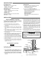
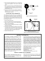
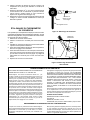
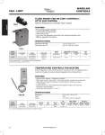
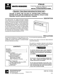
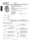
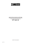
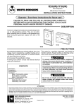
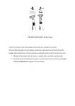
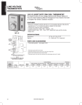
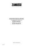
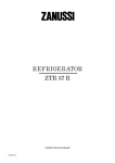
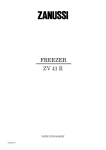
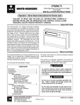
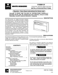
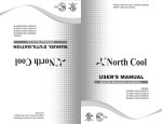
1E56(W) / 1F56(W)
WHITE-RODGERS
Low Voltage Heating/Cooling Thermostat
With Sub-base For System and Fan Selection
INSTALLATION INSTRUCTIONS
Operator: Save these instructions for future use!
FAILURE TO READ AND FOLLOW ALL INSTRUCTIONS CAREFULLY
BEFORE INSTALLING OR OPERATING THIS CONTROL COULD CAUSE
PERSONAL INJURY AND/OR PROPERTY DAMAGE.
DESCRIPTION
This low voltage thermostat is designed to provide convenient control of the heating/cooling system. To provide
greater room comfort, the sensitive spiral bimetal is combined with an adjustable heating anticipator and a fixed
cooling anticipator to provide maximum comfort.
1F56
1E56
If in doubt about whether your wiring is millivolt, line, or low
voltage, have it inspected by a qualified heating and air
conditioning contractor, electrician, or someone familiar
with basic electricity and wiring.
PRECAUTIONS
This control is a precision instrument, and should be
handled carefully. Rough handling or distorting components could cause the control to malfunction.
! CAUTION
Do not exceed the specification ratings.
All wiring must conform to local and national electrical
codes and ordinances.
To prevent electrical shock and/or equipment
damage, disconnect electric power to system at
main fuse or circuit breaker box until installation
is complete.
CONTENTS
Description ..............................................................................
Precautions .............................................................................
Specifications ..........................................................................
Installation ...............................................................................
Select Thermostat Location
Route Wires to Location
Attach Subbase to Wall
Attach Thermostat to Subbase
Operation & Maintenance .......................................................
Adjusting Heat Anticipator
Calibrating Thermostat
1
1
2
2
5
!
WARNING
Do not use on circuits exceeding 30 volts. Higher
voltage will damage control and could cause shock
or fire hazard.
Do not short out terminals on gas valve or primary
control to test. Short or incorrect wiring will burn
out heat anticipator and could cause personal
injury and/or property damage.
ATTENTION!
This product contains mercury. There will not be any exposure to mercury under normal conditions of use. This product may replace a unit which contains mercury.
Do not open mercury cells. If a cell becomes damaged, do not touch any spilled mercury. Wearing non-absorbent gloves, take up the spilled mercury with sand
or other absorbent material and place into a container which can be sealed. If a cell becomes damaged, the unit should be discarded. Mercury must not be
discarded in household trash. When this unit or the unit it is replacing is to be discarded, place in a suitable container and return to us at WHITE-RODGERS.
WHITE-RODGERS DIVISION
EMERSON ELECTRIC CO.
9797 REAVIS RD., ST. LOUIS, MO. 63123
(314) 577-1300, FAX (314) 577-1517
9999 HWY. 48, MARKHAM, ONT. L3P 3J3
(905) 475-4653, FAX (905) 475-4625
PART NO. 37-5327E
Printed in U.S.A.
Replaces 37-5327D
9823
SPECIFICATIONS
ELECTRICAL DATA
Switch Rating: 24 VAC (30 VAC max.)
Heating - 0.15 to 1.2 Amps
Cooling - 0 to 1.5 Amps
Switch Action: SPDT - Sealed mercury switch
APPLICATIONS:
The 1E56(W) / 1F56(W) is designed for use with
• Standard heating and cooling systems
• Two-transformer systems
This thermostat CAN NOT BE USED with
• Millivolt systems (self-generating systems that do
not have a transformer or relay)
• Three-wire zone valve systems
• Multi-stage applications
• Heat-pump systems
• Electric heat furnace where thermostat must
energize fan.
Anticipator Rating:
Heating - Adjustable from 0.15 to 1.2 Amps
Cooling - Fixed 24 VAC
THERMAL DATA
Temperature Range: 10° to 32°C (50° to 90°F)
Differential: 1/2°C (1°F)
INSTALLATION
3. Probe for obstructions in partition before drilling 1/2" hole
in wall at selected location. Take up quarter round and
drill a small guide hole for sighting (see Fig. 1). From
basement, drill 3/4" hole in partition floor next to guide
hole. In basementless houses, drill 1/2" hole through
ceiling and into partition from above (see Fig. 1).
4. Through this hole drop a light chain, or 6" chain
attached to a strong cord. Snag cord in basement with
hooked wire. In basementless houses, drop cord
through hole in ceiling and down partitioning; snag
cord at the thermostat location.
5. Attach thermostat wires to cord and pull thermostat
wires through hole in wall so that 6" of wire protrudes.
SELECT THERMOSTAT LOCATION
Proper location insures that the thermostat will provide a
comfortable home temperature. Observe the following
general rules when selecting a location.
1. Locate thermostat about 5 ft. above the floor.
2. Install thermostat on a partitioning wall, not on an
outside wall.
3. Never expose thermostat to direct light from lamps,
sun, fireplaces or any temperature radiating equipment.
4. Avoid locations close to windows, adjoining outside
walls, or doors that lead outside.
5. Avoid locations close to air registers or in the direct path
of air from them.
6. Make sure there are no pipes or duct work in that part
of the wall chosen for the thermostat location.
7. Never locate thermostat in a room that is warmer or
cooler than the rest of the home, such as the kitchen.
8. Avoid locations with poor air circulation, such as behind
doors or in alcoves.
9. The living or dining room is normally a good location,
provided there is no cooking range or refrigerator on
opposite side of wall.
! CAUTION
To prevent electrical shock and/or equipment
damage, disconnect electric power to system at
main fuse or circuit breaker box until installation
is complete.
1⁄2” hole for
thermostat wire
Stout cord with 6”
chain attached
ROUTE WIRES TO LOCATION
Approximately
5 feet from floor
Baseboard
strip moulding
NOTE
1⁄4” guide hole
for sighting
All wiring must conform with local and national electrical
codes and ordinances.
Quarter round
removed
1. If an old thermostat is being replaced and is in a
satisfactory location, and the wiring appears to be in
good condition, use existing wiring. If in doubt, rewire.
2. If a new location is chosen or if this is a new installation,
thermostat wiring must first be run to the location
selected.
3⁄4” hole in floor of partition
Hooked wire for snagging chain
Figure 1. Routing thermostat wires
2
FAN
NOTE
AUTO
All diagrams show the 1F56(W) horizontal model,
turn subbase 90° for 1E56(W) vertical model.
SYSTEM
ON
COOL OFF HEAT
G
RC
ATTACH SUBBASE TO WALL
1. Pull wires through opening near centre of subbase and
connect wires beneath terminal screws (see figs. 3 to
8).
2. Push excess wiring into wall and plug hole with fireresistant material (such as fiberglass insulation) to
prevent drafts from affecting thermostat operation.
3. Position subbase over hole in wall and mark mounting
hole locations on wall.
4. Drill mounting holes.
5. Fasten subbase loosely to wall, as shown, using two
mounting screws. Place a level against bottom of subbase, adjust until level, and then tighten mounting
screws to secure subbase. If holes in wall are too large
and do not allow you to tighten subbase snugly, use
plastic expansion plugs to secure subbase (see fig. 2).
RH
Y
W
Mounting screw
Hole
in wall
KEEP THIS AREA
CLEAR OF WIRES
Mounting screw
Figure 2. Thermostat subbase
NOTE
These typical wiring diagram show only the terminal
identification and wiring hookup. Always refer to wiring
instructions, provided by Equipment Manufacturer, for
system hookup operation.
Cool
All wiring should be installed
according to local and national
electrical codes and ordinances.
THERMOSTAT
Fixed
Cooling
Anticipator
Heat
Bimetal
Adjustable
Heating
Anticipator
Captive
Screws
Fan
Switch
L
COO
OFF
HEA
T
SUBBASE
AUTO
ON
L
COO
OFF
System
Switch
HEA
T
G
RC
Y
RH
W
Figure 3. Thermostat /subbase diagram
KEEP THIS
AREA CLEAR
OF WIRES!
KEEP THIS
AREA CLEAR
OF WIRES!
G
G
Field-installed
jumper wire
RC
THERMOSTAT
WIRING
RC
THERMOSTAT
WIRING
RH
Y
W
RH
Y
JUMPER WIRE
W
Y
Y
G
W
RC
G
W
RC
Fan
Relay
Heating
System
RH
RH
SYSTEM
NOTE
SYSTEM
Heating
System
RED jumper wire (provided
with thermostat) must be
connected between thermostat's RH and RC terminals
for proper thermostat operation with this system.
Hot
24 VAC
120 VAC
Neutral
TRANSFORMER
Figure 4. Heating only, 2-wire,
single transformer systems
Hot
24 VAC
Figure 5. Heat-only, 3-wire,
single transformer systems
3
120 VAC
Neutral
TRANSFORMER
KEEP THIS
Field-installed
AREA CLEAR
OF WIRES!
G
RC
jumper wire
THERMOSTAT
WIRING
RH
Y
W
JUMPER WIRE
Y
G
W
RC
KEEP THIS
AREA CLEAR
OF WIRES!
RH
G
RC
SYSTEM
NOTE
RED jumper wire (provided
with thermostat) must be
connected between thermostat's RH and RC terminals
for proper thermostat operation with this system.
Cooling
System
Fan
Relay
THERMOSTAT
WIRING
Hot
24 VAC
120 VAC
RH
Neutral
Y
TRANSFORMER
Figure 6. Cool only, 3-wire,
single transformer systems
Y
G
W
RC
W
RH
SYSTEM
Hot
KEEP THIS
AREA CLEAR
OF WIRES!
G
Field-installed
jumper wire
RC
Cooling
System
Fan
Relay
Heating
System
24 VAC
120 VAC
Neutral
HEATING TRANSFORMER
THERMOSTAT
WIRING
Hot
24 VAC
RH
120 VAC
Neutral
Y
W
COOLING TRANSFORMER
Figure 8. Heat/cool, 5-wire,
two-transformer systems
JUMPER WIRE
Y
G
W
Cooling
System
Fan
Relay
Heating
System
RC
RH
SYSTEM
NOTE
RED jumper wire (provided
with thermostat) must be
connected between thermostat's RH and RC terminals
for proper thermostat operation with this system.
Hot
24 VAC
120 VAC
Neutral
TRANSFORMER
Figure 7. Heat/cool, 4-wire,
single transformer systems
! CAUTION
Take care when securing and routing wires so
they do not short to adjacent terminals or rear of
thermostat. Personal injury and/or property damage may occur.
ATTACHING THERMOSTAT TO SUBBASE
FA
TO N
AU
1. Remove cover from thermostat base by gripping the
base in one hand. Use the other hand to pull gently at
the top or bottom of the cover.
2. Carefully remove the shipping protective packing from
the switch.
3. Attach thermostat base to subbase, being sure that all
captive screws are tightened snugly, since they serve
as electrical connections between thermostat and
subbase (see fig. 9).
4. Snap cover on thermostat and set temperature lever to
desired set point.
ON
CO SYS
OL TEM
OF
F
HE
AT
Subbase
Cover
Thermostat
Figure 9. Attach Thermostat to Subbase
4
OPERATION &
MAINTENANCE
This thermostat is easy to operate. Fig.
10 shows how the heating/cooling system and fan operate when the switches
are in various positions. Use the system
switch to select either heating or cooling,
or to turn the heating/cooling system off.
Use the fan switch to control fan operation. When the fan switch is in the AUTO
position, the fan will cycle with the heating
or cooling system (the fan will not run if
the system switch is in the OFF position
and the fan switch is in the AUTO position). When the fan switch is in the ON
position, the fan will run continuously,
regardless of system switch position (even
if the system switch is set to OFF, the fan
will run if the fan switch is in the ON
position).
Shows switch position
FAN
SYSTEM
OPERATION
AUTO
ON
COOL OFF HEAT
No heating; no cooling; no fan
No heating; no cooling; fan runs continuously
Cooling system cycles from thermostat; fan runs
continuously
Cooling system and fan cycle from thermostat
Heating system cycles from thermostat; fan cycles
from fan control on furnace
Heating system cycles from thermostat; fan runs
continuously
Figure 10. Subbase switching and thermostat/system operation
ADJUSTING HEAT ANTICIPATOR
CALIBRATING THERMOSTAT
This thermostat has been carefully adjusted at the factory
and should not require recalibration.
! CAUTION
The adjustable heat anticipator WILL BURN OUT
if 25 VAC is applied directly to the thermostat by
shorting out the primary control during testing.
This may cause personal injury and/or property
damage.
Due to environmental conditions, during normal operation
there may be a few degrees difference between the
indicator setting of the thermostat and actual room
termperature. If the disagreement is appreciable, however, first make sure that the thermostat is properly
located and leveled. Then, if recalibration still seems
necessary, proceed as follows:
This thermostat is equipped with an adjustable heat
anticipator and was preset at the factory to provide
satisfactory operation of the heating system under normal
conditions. If additional adjustments are necessary, they
may be made as follows (see Fig. 11):
! CAUTION
To prevent electrical shock and/or equipment
damage, disconnect electrical power to system
until recalibration is complete.
1. Remove thermostat cover.
2. If heat cycle is too long, set heat anticipator to a slightly
lower dial setting (1/2 division).
3. If heat cycle is too short, set heat anticipator to a
slightly higher dial setting (1/2 division).
4. Replace thermostat cover.
1. The anticipator's heat may adversely affect thermostat
recalibration. To prevent this, disconnect electrical
power to thermostat at the furnace, main fuse, or
breaker box.
2. Move temperature adjustment lever to a setting about
5° above room temperature.
3. Remove thermostat cover. Slip 7/32" wrench onto hex
nut beneath bimetal. While holding temperature adjustment lever stationary, turn hex nut clockwise until
mercury shifts to right end of tube (see Fig. 12).
4. Move temperature adjustment lever to lowest setting.
5. Replace thermostat cover. Wait 10 minutes for bimetal
temperature to stabilize. Do not stand near the thermostat during this period as your breath and body heat will
affect bimetal temperature.
.3 .25
O
NG
ER
YCLES
.5
C
L
.4
.6
.8 1.2
Arrow points to the
matched current rating
of the primary control
.2
.18
.15
Move this lever to
adjust heat
anticipator
Figure 11. Anticipator Adjustment
5
6. Move temperature adjustment lever to correspond to
actual room temperature. Then remove thermostat
cover.
7. Slip 7/32" wrench onto hex nut. While holding temperature adjustment lever stationary, turn hex nut counterclockwise until mercury just barely shifts to left end of
the tube (see Fig. 12).
8. Replace the thermostat cover and set temperature
adjustment lever to desired temperature. Turn on
electrical power to system.
Bimetal
7/32" Calibration
Wrench
CALIBRATING COVER THERMOMETER
The reading on the thermometer may vary slightly from
the actual room temperature. However, if the thermometer reading on the cover is significantly different from the
room temperature, calibrate the cover thermometer using
the following procedure.
1. Remove thermostat cover.
2. Set cover on table near an accurate thermometer.
3. Allow at least ten minutes for the thermometers to
adjust to room temperature.
4. If the thermometer readings are the same, no adjustments are necessary.
5. If the thermometer readings are different, insert a small
screwdriver blade into the thermometer shaft on the
back of the cover (see Fig. 13). Adjust until the cover
thermometer matches the other thermometer.
6. Replace thermostat cover.
Temperature
Adjustment
Lever
Figure 12. Calibrating Thermostat
Thermometer
adjustment
Back side of thermostat cover
Figure 13. Calibrating Thermostat Thermometer
WARRANTY INFORMATION
THIS WARRANTY STATEMENT SUPERSEDES ALL WARRANTY STATEMENTS DATED PRIOR TO JANUARY 1, 1992.
White-Rodgers Division of Emerson Electric Co, (“Seller”) warrants that its products purchased for resale (the “Products”) will be
free from defects in material and workmanship under normal use
and service for a period of twelve (12) months from date of
installation. Seller’s obligation under this warranty, and Purchaser’s
exclusive remedy for the breach thereof, shall be limited to, at
Seller’s option, Seller’s replacement of any defective Product.
F.O.B. Seller’s factory, or Seller’s issuance of a credit in the
amount of the purchase price of such Product for resale as
described below. Seller shall have the option of requiring the return
of any defective Product, transportation charges prepaid, before
recognizing any claim. This warranty shall not apply to any Product
(1) which has been repaired or altered outside Seller’s factory or
by other than Seller in any manner so as in Seller’s judgement, to
affect its serviceability or proper operation; (2) which has been
subjected by persons other than Seller to improper handling,
operation, maintenance, repair or alteration; or (3) which has been
subjected to misuse, negligence or accident.
This warranty extends only to persons or organizations who purchase the Products for resale. THE FOREGOING CONSTITUTES
SELLER’S SOLE RESPONSIBILITY UNDER THIS WARRANTY,
AND PURCHASER’S EXCLUSIVE REMEDY FOR BREACH
THEREOF. EXCEPT AS OTHERWISE EXPRESSLY SET FORTH
IN THIS AGREEMENT, THERE ARE NO OTHER WARRANTIES,
EXPRESS OR IMPLIED, WHETHER OF MERCHANTABILITY,
FITNESS FOR A PARTICULAR PURPOSE, OR OTHERWISE.
SELLER SHALL NOT BE LIABLE FOR ANY SPECIAL, INDIRECT,
INCIDENTAL OR CONSEQUENTIAL DAMAGES IN CONNECTION WITH THE SALE, RESALE OR USE OF THE PRODUCTS.
Complete warranty information and instructions for replacing/returning warranty products can be found in the White-Rodgers
Product Catalogue, or by telephoning or writing to:
WHITE-RODGERS DIVISION
EMERSON ELECTRIC CANADA LIMITED
9999 HIGHWAY 48
MARKHAM, ONTARIO L3P 3J3
TELEPHONE: (905) 475-4653 FAX: (905) 475-4625
WARRANTY INFORMATION FOR CONSUMERS
When you purchase a White-Rodgers Division product, it is
typically for replacement of a device which has failed on existing
residential or commercial equipment, or a component of new
equipment purchased for modernization.
While our warranty does not extend to you, your contractor or dealer
is protected by a one-year product warranty from White-Rodgers.
Your supplier can rely on a nearby White-Rodgers wholesaler for
prompt credit or replacement.
1E56(W) / 1F56(W)
WHITE-RODGERS
Thermostat à basse tension de chauffage et climatisation
avec socle de commande du système et du ventilateur
INSTRUCTIONS D’INSTALLATION
Utilisateur : conservez ces instructions pour vous y référer au besoin !
SI VOUS NE LISEZ PAS ATTENTIVEMENT CES INSTRUCTIONS AVANT
D’INSTALLER ET D’UTILISER LA COMMANDE, VOUS RISQUEZ DE CAUSER
DES BLESSURES ET DES DOMMAGES MATÉRIELS.
DESCRIPTION
Ce thermostat à basse tension a été conçu comme commande
pratique des systèmes de chauffage et climatisation. Dans le but
de vous offrir le plus grand confort possible, le bilame sensible
en spirale est couplé à deux éléments anticipateurs, l’un réglable
pour le chauffage et l’autre fixe pour la climatisation.
1F56
1E56
Si vous n’êtes pas certain de la tension du câblage de votre
système (soit en millivolts, à basse tension ou à la tension du
réseau), faites inspecter celui-ci par un électricien, un entrepreneur agréé en chauffage et climatisation ou une personne
qui a des connaissances de base en électricité et en câblage.
Ne dépassez pas les charges nominales.
Tout le câblage doit être conforme aux codes et règlements
locaux et nationaux qui régissent les installations électriques.
PRÉCAUTIONS
Cette commande est un instrument de précision qui doit être
manipulé avec soin. Elle peut se détraquer si elle est manipulée
de façon négligente ou si des composantes sont déformées.
! ATTENTION
Afin de prévenir les chocs électriques et les dommages
matériels pendant l’installation, couper l’alimentation
électrique au panneau de distribution principal.
!
TABLE DES MATIÈRES
Description ...............................................................................
Précautions ..............................................................................
Spécifications ...........................................................................
Installation ................................................................................
Choix du site pour le thermostat
Acheminement du câblage au site
Installation du socle sur le mur
Installation du thermostat sur le socle
Mode d’emploi et entretien .......................................................
Réglage de l’anticipation de chauffage
Étalonnage du thermostat
AVERTISSEMENT
1
1
2
2
Ne vous servez pas de cette commande sur des circuits
dont la tension dépasse 30 volts. La surtension risque
d’endommager la commande et pose un risque
d’électrocution et d’incendie.
5
Ne court-circuitez pas les bornes du robinet de gaz ou
de la commande principale pour effectuer des essais.
Les court-circuit et câblage inadéquat endommagerent l’anticipateur de chauffage et risquent
d’entraîner des blessures et des dommages matériels.
ATTENTION !
Cet appareil contient du mercure. Il n’y a aucun risque d’exposition lorsque l’appareil est utilisé normalement. Cet appareil peut en remplacer
un autre qui, lui, contient du mercure. N’ouvrez pas les cellules de mercure. Si une cellule est endommagée, ne touchez pas au mercure qui
s’en échappe. Enfilez des gants étanches et nettoyez le mercure avec du sable ou une autre substance absorbante, puis placez le matériel
contaminé dans un contenant qui peut être fermé hermétiquement. Si une cellule est endommagée, l’appareil en entier doit être jeté. Ne pas
jeter de mercure avec les ordures ménagères. Si vous devez jeter cet appareil ou celui qu’il remplace, placez-le dans un contenant
convenable et faites-le parvenir à WHITE-RODGERS.
WHITE-RODGERS DIVISION
EMERSON ELECTRIC CO.
9797 REAVIS RD., ST. LOUIS, MO. 63123
(314) 577-1300, Télécopieur (314) 577-1517
9999 HWY. 48, MARKHAM, ONT. L3P 3J3
(905) 475-4653, Télécopieur (905) 475-4625
PIÈCE NO 37-5327E
Imprimé au É.-U.A.
Remplace 37-5327D
9820
SPÉCIFICATIONS
FICHE ÉLECTRIQUE
Charges du commutateur : 24 V c.a. (maxi 30 V c.a.);
Chauffage : 0,15 à 1,2 A;
Climatisation : 0 à 1,5 A.
Commutation : Unipolaire bidirectionnelle (SPDT)
à bulle de mercure scellé.
Anticipation :
Chauffage : Réglable de 0,15 à 1,2 A;
Climatisation : Fixe à 24 V c.a.
FICHE THERMIQUE
Plage des points de consigne : 10°C à 32°C (50°F à 90°F).
Différentiel : 1/2°C (1°F).
APPLICATIONS :
Le 1E56(W) / 1F56(W) a été conçu pour servir avec :
• Les systèmes ordinaires de chauffage et climatisation;
• Les systèmes à deux transformateurs.
Ce thermostat NE PEUT PAS SERVIR avec :
• Les systèmes millivolts (systèmes sans transformateur
ni relais)
• Les systèmes à trois fils à soupapes de zone;
• Les systèmes à plusieurs étages;
• Les systèmes à thermopompe;
• Les appareils de chauffage électriques dont le
thermostat doit mettre le ventilateur sous tension.
INSTALLATION
CHOIX D’UN SITE POUR LE THERMOSTAT
3. Assurez-vous qu’il n’y a pas d’obstacle dans le mur avant d’y
percer un trou de 1/2" à l’endroit choisi. Enlevez ensuite le
quart-de-rond et percez un petit trou de guidage (figure 1).
Au sous-sol, percez un trou de 3/4" dans le plancher de la
cloison, à côté du trou de guidage. Dans les bâtiments sans
sous-sol, percez le trou de 1/2" dans le plafond, entre les
parois de la cloison (figure 1).
4. Passez par le trou que vous avez percé dans le mur une
chaînette ou une corde solide avec une chaînette de 6”
attachée au bout. Accrochez la chaînette au sous-sol à
l’aide d’un crochet de fil de fer. Dans les maisons sans soussol, passez la chaînette par le trou percé dans le plafond et
accrochez-le par celui que vous avez percé dans le mur.
5. Attachez le câblage du thermostat à la corde et faites-le
passer par le trou dans le mur; laissez pendre 6" de câblage.
Pour que le thermostat puisse assurer une température ambiante
confortable, il doit être installé dans un site adéquat. Choisissez
le site en tenant compte des recommandations suivantes :
1. Placez le thermostat environ à 1,5 m (5 pieds) du sol.
2. Installez le thermostat sur une cloison intérieure et non sur
un mur extérieur.
3. N’exposez pas le thermostat directement à la lumière de
lampes, aux rayons du soleil, ni à la chaleur d’un foyer ou
d’un radiateur.
4. Évitez les endroits près d’une fenêtre ou encore d’un mur ou
d’une porte extérieurs.
5. Évitez les endroits qui sont près des bouches d’air ou dans
la trajectoire de l’air qui en émane.
6. Assurez-vous qu’il n’y a pas de tuyaux ni de conduites dans
le mur à proximité du site du thermostat.
7. N’installez jamais le thermostat dans une pièce qui est
habituellement plus chaude ou plus froide que le reste du
domicile, comme la cuisine, par exemple.
8. Évitez les endroits où la circulation d’air se fait mal, comme
les alcôves et l’arrière des portes.
9. La salle à diner et le salon sont généralement des endroits
propices s’il n’y a pas de cuisinière ou de réfrigérateur
adossé au mur derrière le thermostat.
! ATTENTION
Afin de prévenir les chocs électriques et les dommages
matériels pendant l’installation, couper l’alimentation
électrique au panneau de distribution principal .
Trou de 1⁄2" pour
le câblage du thermostat
ACHEMINEMENT DU CÂBLAGE AU SITE
NOTE
Corde solide attachée
à une chaîne de 6"
Tout le câblage doit être conforme aux codes et règlements
locaux et nationaux qui régissent les installations électriques.
1. Si vous remplacez un thermostat dont l’emplacement est
adéquat et si le câblage semble être en bon état, servezvous du câblage déjà en place. En cas d’incertitude, câblez
à neuf.
2. Si vous choisissez un nouvel emplacement ou encore si
vous installez à neuf, vous devrez commencer par acheminer
le câblage au site choisi.
Environ
5 pieds
Plinthe
Trou de guidage
de 1⁄4"
Quart-de-rond
enlevé
Trou de 3⁄4" dans le plancher
de la cloison
Fil de fer replié pour accrocher la chaîne
Figure 1. Acheminement du câblage au site
2
FAN
NOTE
AUTO
Tous les schémas illustrent le modèle horizontal
1F56(W). Pour le modèle vertical 1E56(W), tournez le
socle de 90° de façon à l’orienter à la verticale.
SYSTEM
COOL OFF HEAT
ON
G
RC
INSTALLATION DU SOCLE SUR LE MUR
1. Faites passer les fils dans l’ouverture au centre du socle et
raccordez les fils sur les bornes à vis (figures 3 et 8).
2. Repoussez dans le mur le surplus de fil et bouchez le trou
avec un produit ignifuge (comme de la mousse isolante en
fibre de verre) afin d’empêcher que des courants d’air
n’affectent le fonctionnement du thermostat.
3. Placez le socle du thermostat sur le mur, devant le trou de
passage des câbles, et reportez sur le mur l’emplacement
des trous de montage.
4. Percez les trous de montage.
5. À l’aide des deux vis de montage, fixez lâchement le socle
de la façon illustrée. Placez un niveau sous le socle et
ajustez celui-ci pour qu’il soit de niveau. Serrez ensuite les
vis pour fixer le socle. Si les trous de montage sont trop
grands et ne vous permettent pas de fixer solidement le
socle, servez-vous des chevilles de plastique pour l’assujettir
(figure 2).
RH
Y
W
Trou dans Vis de montage
le mur
ÉCARTEZ LES FILS
DE CET ENDROIT
Vis de
montage
Figure 2. Socle du thermostat
NOTE
Le schéma de câblage typique illustre uniquement l’identification
des bornes et le raccordement des fils. Pour raccorder le
système, référez-vous toujours aux directives de câblage fournies
par le fabricant de l’équipement.
Climat.
Tout le câblage doit être conforme aux
codes et règlements locaux et nationaux
qui régissent les installations
électriques.
Anticipateur
fixe de
Climat.
THERMOSTAT
Chauf.
Bilame
Anticipateur
de chauf.
réglable
Vis
Captives
L
COO
OFF
HEA
T
SOCLE
AUTO
ON
L
COO
OFF
Commutateur
du
Ventilateur
Commutateur
du System
HEA
T
G
RC
Y
RH
W
Figure 3. Schéma du thermostat et du socle
ÉCARTEZ LES
FILS DE
ÉCARTEZ LES
FILS DE
CET ENDROIT
G
CET ENDROIT
G
Cavalier
raccordé
sur place
RC
RC
CÂBLAGE DU
THERMOSTAT
CÂBLAGE DU
THERMOSTAT
RH
RH
Y
Y
G
W
RC
Y
W
CAVALIER
Y
RH
NOTE
Sous tension
24 V c.a.
G
W
RC
RH
SYSTÈME
SYSTÈME
Système du
chauf.
W
Pour assurer le bon fonctionnement de l'appareil avec ce
type système, le cavalier
ROUGE (foumi avec le thermostat) doit relier les bornes
RH et RC du thermostat
120 V c.a.
Neutre
TRANSFORMATEUR
Relais
vent.
Système du
Chauf.
Sous tension
24 V c.a.
120 V c.a.
Neutre
TRANSFORMATEUR
Figure 4. Chauffage seulement à 2 fils
et un transformateur
Figure 5. Chauffage seulement à 3 fils
et un transformateur
3
ÉCARTEZ LES
FILS DE
G
CET ENDROIT
Cavalier
raccordé
RC
sur place
CÂBLAGE DU
THERMOSTAT
RH
Y
W
ÉCARTEZ LES
FILS DE
CET ENDROIT
CAVALIER
Y
G
W
RC
G
RC
CÂBLAGE DU
THERMOSTAT
RH
SYSTÈME
NOTE
Pour assurer le bon fonctionnement de l'appareil avec ce
type système, le cavalier
ROUGE (foumi avec le thermostat) doit relier les bornes
RH et RC du thermostat
Relais
vent.
Système du
chauf.
RH
Sous tension
24 V c.a.
120 V c.a.
Y
W
Neutre
TRANSFORMATEUR
Y
G
W
RC
RH
SYSTÈME
Figure 6. Climatisation seulement à 3 fils
et un transformateur
Sous tension
Système du Relais
Climat.
vent.
Système du
Chauf.
24 V c.a.
120 V c.a.
Neutre
ÉCARTEZ LES
FILS DE
CET ENDROIT
G
TRANSFORMATEUR DU
CHAUFFAGE
Cavalier
raccordé
sur place
RC
Sous tension
24 V c.a.
120 V c.a.
CÂBLAGE DU
THERMOSTAT
Neutre
TRANSFORMATEUR DU CLIMATISATION
RH
Y
Figure 8. Chauffage et climatisation à 5 fils
et deux transformateurs
W
CAVALIER
Y
G
W
RC
RH
SYSTÈME
NOTE
Pour assurer le bon fonctionnement de l'appareil avec ce
type système, le cavalier
ROUGE (foumi avec le thermostat) doit relier les bornes
RH et RC du thermostat
Système du
Climat.
Relais Système du
vent.
Chauf.
Sous tension
24 V c.a.
120 V c.a.
Neutre
TRANSFORMATEUR
Figure 7. Chauffage/Climatisation à 4 fils
et un transformateur
! ATTENTION
Lorsque vous acheminez et fixez le câblage, assurezvous qu’aucun fil ne court-circuite une borne adjacente
ou l’arrière du thermostat. Ceci pourrait causer des
blessures et des dommages matériels.
INSTALLATION DU THERMOSTAT
SUR LE SOCLE
FA
TO N
AU
ON
CO SYS
OL TEM
OF
F
HE
AT
1. Pour détacher le couvercle du thermostat, saisissez le thermostat d’une main et, de l'autre, tirez doucement le haut ou le
bas du couvercle.
2. Retirez soigneusement l’emballage qui protège le
commutateur.
3. Fixez le thermostat sur le socle. Assurez-vous que les vis
captives sont vissées à fond, car elles servent de raccordement électrique entre le thermostat et le socle (figure 9).
4. Engagez le couvercle sur le thermostat et placez la manette
de réglage du point de consigne au niveau désiré.
Socle
Thermostat
Couvercle
Figure 9. Installation du thermostat sur le socle
4
MODE D’EMPLOI
ET D’ENTRETIEN
Ce thermostat est facile d’usage. La figure 10
illustre le fonctionnement du système de
chauffage ou de climatisation en fonction du
réglage des commutateurs. Le commutateur
de système permet, d’une part, de choisir entre
le chauffage et la climatisation et, d’autre part,
de mettre l’appareil de chauffage ou de
climatisation hors tension. Quant au
commutateur de ventilateur, il sert à commander
ce dernier : réglé à la position AUTO, le
ventilateur se mettra sous tension et hors
tension en même temps que le systéme de
chauffage ou de climatisation (le ventilateur ne
démerrera jamais si le commutateur de systéme
est à la position OFF [ARRÊT] alors que le
commutateur de ventilateur est à la position
AUTO). Lorsque le commutateur de ventilateur
est réglé à la position ON (MARCHE), le
ventilateur fonctionnera sans arrêt, peu importe
la position du commutateur de systéme (même
si ce dernier est à la position OFF [ARRÊT]).
Position du commutateur
FAN
SYSTEM
FONCTIONS
AUTO
ON
COOL OFF HEAT
Pas de chauffage; pas de climatisation; ventilateur à l'arrêt
Pas de chauffage; pas de climatisation; le ventilateur est
continuellement en marche
Le système de climatisation est commandé par le
thermostat; le ventilateur est continuellement en marche
Le système de climatisation et le ventilateur sont
commandés par le themostat
Le système de chauffage est commandé par le thermostat;
le ventilateur est commandé par l'appareil de chauffage
Le système de chauffage est commandé par le thermostat;
le ventilateur est continuellement en marche
Figure 10. Fonctionnement du systéme et du ventilateur
en fonction de la position des commutateurs de socle
RÉGLAGE DE L’ANTICIPATION
DE CHAUFFAGE
ÉTALONNAGE DU THERMOSTAT
Le thermostat a été réglé avec soin en usine. Il ne devrait pas
être nécessaire de l’étalonner.
En usage normal, les conditions atmosphériques peuvent
entraîner une différence de quelques degrés entre le point de
consigne et la température ambiante de la pièce. Si cette
différence est significative, assurez-vous d’abord que le
thermostat est de niveau et que son emplacement a été bien
choisi. Si l’étalonnage semble encore nécessaire, veuillez
procéder de la façon suivante :
! ATTENTION
L’élément anticipateur réglable SERA GRILLÉ si vous
raccordez le thermostat directement sur du courant de
25 V c.a. en court-circuitant la commande principale
lors d’essais. Ceci peut entraîner des blessures et des
! ATTENTION
Le thermostat est doté d’un anticipateur réglable de chauffage.
Il a été réglé à l’usine de façon à commander adéquatement le
système de chauffage utilisé dans des conditions normales. Si
un réglage s'avère nécessaire, procédez de la façon suivante
(figure 11).
1. Détachez le couvercle du thermostat.
2. Si les cycles de chauffage sont trop longs, diminuez légèrement le réglage de l'élément anticipateur (1/2 graduation).
3. Si les cycles de chauffage son trop courts, augmentez
légèrement le réglage de l'élément anticipateur (1/ 2
graduation).
4. Replacez le couvercle du thermostat.
Afin de prévenir les chocs électriques et les dommages
matériels pendant l’installation, couper l’alimentation
électrique au panneau de distribution principal .
1. La chaleur de l’élément anticipateur peut affecter l’étalonnage
du thermostat. Dans le but d’éviter ce problème, coupez
l’alimentation en provenance de l’appareil de chauffage ou
du panneau de distribution électrique.
2. Placez la manette de réglage du point de consigne environ
à 5° au-dessus de la température ambiante.
3. Détachez le couvercle du thermostat. Glissez un clé anglaise
de 7/32" sur l’écrou hexagonal situé sous le bilame. Tout en
maintenant en place la manette de régalge, tournez l’écrou
à droite jusqu’à ce que le mercure se déplace vers la droite
du tube (figure 12).
4. Placez la manette de réglage du point de consigne à son
niveau le plus bas.
5. Replacez le couvercle du thermostat. Attendez 10 minutes
que la température du bilame se stablise. Ne vous tenez pas
à proximité du thermostat durant cette période, car votre
souffle et la chaleur de votre corps pourraient affecter la
température du bilame.
.3 .25
O
NG
YCLES
.5
ER
C
L
.4
.6
.8 1.2
La flèche indique le
courant correspondant de
la commande principale
.2
.18
.15
Déplacez cette
manette pour régler
l’anticipation
Figure 11. Réglage de l’anticipation
5
6. Placez la manette de réglage du point de consigne à la
température de la pièce, puis détachez le couvercle du
thermostat.
7. Glissez la clé anglaise de 7/32" sur l’écrou hexagonal situé
sous le bilame. Tout en maintenant en place la manette,
tournez l’écrou à gauche jusqu’à ce que le mercure se
déplace vers la gauche du tube (figure 12).
8. Replacez le couvercle sur le thermostat et réglez le point de
consigne au niveau souhaité. Rétablissez le courant qui
alimente le système.
Bilame
Manette de
réglage du point
de consigne
Clé anglaise de 7/32
ÉTALONNAGE DU THERMOMÈTRE
DU COUVERCLE
Il est possible que la température indiquée par le thermomètre
soit légèrement différente de la température ambiante. Si cette
différence est significative, vous pouvez étalonner le thermomètre
du couvercle de la façon suivante :
1. Détachez le couvercle du thermostat.
2. Placez le couvercle sur une table près d'un thermomètre
juste.
3. Attendez au moins dix minutes pour que les thermomètres
s’ajustent à la température ambiante.
4. Si les deux thermomètres indiquent la même température,
alors aucun réglage n’est nécessaire.
5. Si les deux thermomètres ne concordent pas, introduisez la
pointe d’un petit tournevis plat dans l’axe du thermomètre,
qui est situé à l’arrière du couvercle (figure 13). Réglez le
thermomètre du couvercle pour le faire concorder avec
l’autre.
6. Replacez le couvrcle sur le thermostat.
Figure 12. Étalonnage du thermostat
Réglage du
thermomètre
Arrière du couvercle du thermostat
Figure 13. Étalonnage du thermomètre
du thermostat
RENSEIGNEMENTS DE GARANTIE
CET ENONCE DE GARANTIE REMPLACE TOUT ENONCE DE
GARANTIE DATE D’AVANT LE 1er JANVIER 1992.
White-Rodgers, une division de Emerson Electric Co., (“Le
vendeur”) garantit que ses produits achetés pour la revente (”Les
produits”) sont exempts de tout défaut matériel et de maind’oeuvre pour une période d’usage et d’entretien normaux d’une
durée de douze (12) mois à compter de la date d’installation.
L’obligation du vendeur, et le seul recours de l’acheteur, en vertu
de cette garantie, se limite, au choix du vendeur, au remplacement
de tout produit défectueux, franc de port de l’usine du vendeur, ou
à l’émission d’un crédit pour le prix d’achat du produit pour revente,
tel que décrit ci-bas. Le vendeur se réserve le droit d’exiger le
retour de tout produit défectueux, frais de transport payés d’avance,
avant d’accepter une réclamation. Cette garantie ne s’applique à
aucun produit qui (1) a été réparé ou altéré à l’extérieur de l’usine
du vendeur ou par autre que le vendeur de façon telle que, de l’avis
du vendeur, l’appareil ne peut plus fonctionner ni être réparé
adéquatement; (2) a été manipulé, utilisé, réparé ou altéré
incorrectement par tout autre que le vendeur; ou (3) a subi un
emploi abusif, de la négligence ou un accident.
Cette garantie ne s’applique qu’aux personnes physiques et morales
qui achètent ce produit pour la revente. CE QUI PRECEDE
REPRESENTE LA SEULE RESPONSABILITE DU VENDEUR EN
VERTU DE CETTE GARANTIE, AINSI QUE LE SEUL RECOURS
DE L’ACHETEUR. A MOINS D’ETRE EXPRESSEMENT DEFINI
AILLEURS DANS CETTE ENTENTE, IL N’Y A PAS D’AUTRE
GARANTIE, EXPLICITE OU IMPLICITE, QUANT A L’ETAT DE
VENTE, A L’APTITUDE A UNE TACHE, OU A TOUT AUTRE
CRITERE. LE VENDEUR N’EST RESPONSABLE D’AUCUN
DOMMAGE SPECIAL, INDIRECT OU FORTUIT EN RAPPORT
AVEC LA VENTRE, LA REVENTE OU L’UTILISATION DE CES
PRODUITS.
Des renseignements complets sur la garantie ainsi que des directives
sur le remplacement et le retour de produits sous garantie se
retrouvent dans le catalogue de produits White-Rodgers, et peuvent
être obtenus en téléphonant ou en écrivant à:
DIVISION WHITE-RODGERS
EMERSON ELECTRIC CANADA LIMITÉE
9999 HWY48
MARKHAM, ONTARIO L3P 3J3
TÉLÉPHONE: (905) 475-4653 TÉLÉCOPIEUR: (905) 475-4625
RENSEIGNEMENTS DE GARANTIE POUR LES CONSOMMATEURS
Lorsque vous achetez un produit de la Division White-Rodgers,
celui-ci sert généralement à remplacer un appareil d’une installation
résidentielle ou commerciale qui a fait défaut, ou comme
composante d’équipement neuf acheté pour moderniser une
installation.
Bien que notre garantie ne s’applique pas à vous, votre entrepreneur
ou votre marchand est protégé par la garantie d’un an sur les
produits de White-Rodgers. Votre fournisseur peut se fier sur le
grossiste White-Rodgers le plus près pour obtenir rapidement un
crédit ou un appareil de remplacement.