1
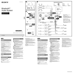
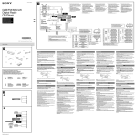
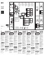
4-440-627-51(1)
*1 Depending on the type of car, use an adaptor (not
supplied) if the antenna connector does not fit.
*2 RCA pin cord (not supplied).
*3 Depending on the type of car, use an adaptor for a
wired remote control (not supplied).
*4 Speaker impedance: 4 – 8 ohms × 4
5
* Whether in use or not, route the microphone input
cord such that it does not interfere with driving. Secure
the cord with a clamp, etc., if it is installed around your
feet.
*6 For details on installing the microphone, see
“Installing the microphone ( )” on the reverse side.
*
2
®
Bluetooth
autoradio
*1 Zavisno od tipa automobila, koristite adapter (opcija)
ako antenski priključak ne odgovara.
*2 RCA pin kabl (nije isporučen).
*3 Zavisno od tipa automobila upotrebite adapter za žični
daljinski upravljač (opcija).
*4 Impedansa zvučnika: 4 – 8 ohma × 4
5
* Bez obzira da li je u upotrebi ili ne, postavite ulazni kabl
za mikrofon tako da vas ne ometa tokom vožnje.
Učvrstite kabl štipaljkom, itd. ako su kablovi postavljeni
blizu vaših stopala.
*6 Za detalje o postavljanju mikrofona, pogledajte
"Postavljanje mikrofona ( )" na drugoj strani.
*1 Selon le type de voiture, utilisez un adaptateur (non
fourni) si le connecteur de l’antenne ne convient pas.
*2 Cordon à broche RCA (non fourni).
*3 Selon le type de voiture, utilisez un adaptateur pour
télécommande filaire (non fournie).
*4 Impédance des haut-parleurs : 4 – 8 ohms × 4
5
* Que vous utilisiez ou non le microphone, acheminez
son cordon de manière à ce qu’il ne gêne pas la
conduite. Fixez le cordon à l’aide d’une attache, par
exemple, si vous l’installez à proximité des pieds.
*6 Pour plus d’informations sur l’installation du
microphone, reportez-vous à la section « Installation
du microphone ( ) » au verso.
Fuse (10 A)
Osigurač (10 A)
Fusible (10 A)
Fusibile (10 A)
Zekering (10 A)
×2
*2
1
×6
Installation/Connections
Ugradnja/povezivanje
Installation/Connexions
Installazione/Collegamenti
Montage/Aansluitingen
2
*6
*1 from car antenna (aerial)
sa automobilske antene
de l’antenne de la voiture
dall’antenna dell’auto
van een auto-antenne
See “Power connection diagram (
*
Equipment used in illustrations (not supplied)
Oprema koja se koristi na ilustracijama (nije isporučena)
Appareils utilisés dans les illustrations (non fournis)
Apparecchiatura utilizzata nelle illustrazioni (non in dotazione)
Apparatuur gebruikt in de afbeeldingen (niet bijgeleverd)
WX-GT90BT
Srpski
Dijagram spajanja (
This unit is designed for negative ground (earth) 12 V
DC operation only.
Do not get the leads under a screw, or caught in moving
parts (e.g. seat railing).
Before making connections, turn the car ignition off to
avoid short circuits.
Connect the power supply lead
to the unit and
speakers before connecting it to the auxiliary power
connector.
Run all ground (earth) leads to a common ground
(earth) point.
Be sure to insulate any loose unconnected leads with
electrical tape for safety.
Notes on the power supply lead (yellow)
When connecting this unit in combination with other
stereo components, the connected car circuit’s rating
must be higher than the sum of each component’s fuse.
When no car circuits are rated high enough, connect the
unit directly to the battery.
Parts list (
)
The numbers in the list are keyed to those in the
instructions.
The bracket
is attached to the unit before shipping.
Before mounting the unit, use the release keys
to
remove the bracket
from the unit. For details, see
“Removing the bracket ( )” on the reverse side of the
sheet.
Keep the release keys for future use as they are
also necessary if you remove the unit from your car.
Caution
Handle the bracket
fingers.
)
Oprez
carefully to avoid injuring your
Connection example (
)
Subwoofer Direct Connection ( -B)
For details on the setting for the connection, see the
supplied Operating Instruction.
* Do not connect a speaker in this connection.
Notes
Be sure to connect the ground (earth) lead before connecting the
amplifier.
The alarm will only sound if the built-in amplifier is used.
If you have a power antenna (aerial) without a relay box,
connecting this unit with the supplied power supply lead
may damage the antenna (aerial).
Notes on the control and power supply leads
REM OUT lead (blue/white striped) supplies +12 V DC when you turn on
the unit.
When using an optional power amplifier, connect REM OUT lead (blue/
white striped) or the accessory power supply lead (red) to its AMP
REMOTE IN.
When your car has built-in FM/MW/LW antenna (aerial) in the rear/side
glass, connect REM OUT lead (blue/white striped) or the accessory
power supply lead (red) to the power terminal of the existing antenna
(aerial) booster. For details, consult your dealer.
A power antenna (aerial) without a relay box cannot be used with this unit.
Memory hold connection
When the yellow power supply lead is connected, power will always be
supplied to the memory circuit even when the ignition switch is turned off.
Notes on speaker connection
Before connecting the speakers, turn the unit off.
Use speakers with an impedance of 4 to 8 ohms, and with adequate
power handling capacities to avoid its damage.
Do not connect the speaker terminals to the car chassis, or connect the
terminals of the right speakers with those of the left speaker.
Do not connect the ground (earth) lead of this unit to the negative (–)
terminal of the speaker.
Do not attempt to connect the speakers in parallel.
Connect only passive speakers. Connecting active speakers (with
built-in amplifiers) to the speaker terminals may damage the unit.
To avoid a malfunction, do not use the built-in speaker leads installed in
your car if the unit shares a common negative (–) lead for the right and
left speakers.
Do not connect the unit’s speaker leads to each other.
Note on connection
If speaker and amplifier are not connected correctly, “FAILURE” appears in
the display. In this case, make sure the speaker and amplifier are
connected correctly.
Power connection diagram
( )
Auxiliary power connector may vary depending on the
car. Check your car’s auxiliary power connector diagram
to make sure the connections match correctly. There are
three basic types ( -1, -2, -3). You may need to
switch the positions of the red and yellow leads in the car
stereo’s power supply lead.
After matching the connections and switched power
supply leads correctly, connect the unit to the car’s power
supply. If you have any questions and problems connecting
your unit that are not covered in this manual, please
consult the car dealer.
Front speaker
Prednji zvučnik
Haut-parleur avant
Diffusore anteriore
Voorluidspreker
Français
Povedite računa da ovaj uređaj ugradite u komandnu
ta blu automobila, budući da se njegova zadnja strana
tokom upotrebe zagreva.
Dizajn i tehnički podaci podložni su promeni bez najave.
Proizvođač ne odgovara za eventualne štamparske greške.
Ovaj uređaj je dizajniran samo za rad pri negativnom
uzemljenju od 12 V DC.
Pripazite da se kablovi ne priklješte ispod vijka ili da ne
uhvate pokretne delove (na primer, vođice sedišta).
Pre povezivanja, isključite motor automobila kako
biste izbegli pojavu kratkog spoja.
Spojite kabl napajanja i zvučnike na uređaj pre
spajanja na priključnicu pomoćnog napajanja.
Sprovedite sve kablove uzemljenja na zajedničku
tačku uzemljenja.
Sve kablove koji nisu spojeni izolujte izolir trakom
radi sigurnosti.
Napomene o kablu napajanja (žuti)
Kad spajate ovaj uređaj zajedno sa drugim audio komponentama, nazivni napon električnog sklopa automobila
treba biti viši od zbira osigurača svake komponente.
Ako električni sklopovi automobila nemaju dovoljno
veliki napon, spojite uređaj direktno na akumulator.
)
Brojevi u listi odgovaraju onima u uputstvu.
Nosač pričvršćuje se na uređaj pre isporuke. Pre
ugradnje uređaja, ključevima za otpuštanje uklonite
nosač sa uređaja. Za detalje pogledajte "Skidanje
nosača ( )" na drugoj strani.
Sačuvajte ključeve za otpuštanje za buduću
upotrebu, pošto su potrebni i za uklanjanje uređaja
iz vašeg automobila.
Oprez
Nosač
–
Speaker, Front, Right
Zvučnik, prednji, desni
Haut-parleur, avant, droit
Diffusore, anteriore, destro
Luidspreker, voor, rechts
4
5
Blue/white striped
Plavo/beli prugasti
Rayé bleu/blanc
Rigato blu e bianco
Blauw/wit gestreept
power antenna (aerial) /power amplifier control (REM OUT)
električna antena/kontrolni izlaz pojačala snage (REM OUT)
commande de l’antenne électrique/amplificateur de puissance (REM
OUT)
antenna elettrica/controllo dell’amplificatore di potenza (REM OUT)
elektrische antenne / versterker (REM OUT)
6
Orange/White
Narandžasto/belo
gestreift
Rayé orange/blanc
Arancione/bianco
Oranje/wit
switched illumination power supply
napajanja osvetljenja
alimentation de l’éclairage commuté
alimentazione illuminazione commutata
geschakelde voeding voor verlichting
Subwoofer
Subwoofer
Caisson de graves
Subwoofer
Subwoofer
Power amplifier
Pojačalo
Amplificateur de puissance
Amplificatore di potenza
Eindversterker
Schéma de raccordement (
7
8
Green
Zeleno
Vert
Verd e
Groen
–
Speaker, Front, Left
Zvučnik, prednji, levi
Haut-parleur, avant, gauche
Diffusore, anteriore, sinistro
Luidspreker, voor, links
+
Speaker, Rear, Left
Zvučnik, zadnji, levi
Haut-parleur, arrière, gauche
Diffusore, posteriore, sinistro
Luidspreker, achter, links
–
Speaker, Rear, Left
Zvučnik, zadnji, levi
Haut-parleur, arrière, gauche
Diffusore, posteriore, sinistro
Luidspreker, achter, links
1
7
Red
Crveno
Rouge
Rosso
Rood
switched power supply
napajanje sa prekidačem
alimentation commutée
alimentazione commutata
geschakelde voeding
8
Black
Crno
Noir
Nero
Zwart
ground (earth)
uzemljenje
masse
terra
aarding
držite pažljivo kako ne biste povredili prste.
Primer povezivanja (
)
Direktno spajanje subwoofer-a ( -B)
Pojedinosti o postavkama spajanja potražite u isporučenom
uputstvu za upotrebu.
* U ovom načinu povezivanja nemojte spajati zvučnik.
Napomene
Pre spajanja pojačala, spojite kabl uzemljenja.
Alarm će se oglasiti samo ako koristite ugrađeno pojačalo.
Red
Crveno
Rouge
Rosso
Rood
Yellow
Žuto
Jaune
Giallo
Geel
Yellow
Žuto
Jaune
Giallo
Geel
4
Yellow
Žuto
Jaune
Giallo
Geel
switched power supply
napajanje sa prekidačem
alimentation commutée
alimentazione commutata
geschakelde voeding
7
Red
Crveno
Rouge
Rosso
Rood
continuous power supply
konstantno napajanje
alimentation continue
alimentazione continua
continue voeding
3
Red
Crveno
Rouge
Rosso
Rood
Red
Crveno
Rouge
Rosso
Rood
Red
Crveno
Rouge
Rosso
Rood
Red
Crveno
Rouge
Rosso
Rood
Yellow
Žuto
Jaune
Giallo
Geel
Yellow
Žuto
Jaune
Giallo
Geel
Yellow
Žuto
Jaune
Giallo
Geel
Yellow
Žuto
Jaune
Giallo
Geel
)
Ako posedujete antenu bez releja, spajanjem ovog uređaja
pomoću isporučenog kabla napajanja može doći do
oštećenja antene.
Napomene o kontrolnom kablu i kablu napajanja
Kabl REM OUT (prugasti plavo-beli) napaja uređaj sa +12 V DC kad ga
uključite.
Kad koristite dodatno pojačalo snage, spojite kabl REM OUT (prugasti
plavo-beli) ili kabl napajanja za dodatni pribor (crveni) na njegov
AMP REMOTE IN.
Ako je vaš automobil opremljen ugrađenom FM/MW/LW antenom na
zadnjem/bočnom staklu, spojite REM OUT kabl antene (prugasti plavobeli) ili kabl napajanja za dodatni pribor (crveni) na priključnicu
napajanja postojećeg antenskog pojačala. Za detalje, obratite se vašem
prodavcu.
Antena bez releja se ne može koristiti sa ovim uređajem.
Spajanje memorijskog napajanja
Kad je spojen žuti kabl napajanja, napajanje se uvek dostavlja memorijskom sklopu čak i kad je prekidač napajanja isključen.
Napomene o spajanju zvučnika
Pre spajanja zvučnika, isključite uređaj.
Upotrebite zvučnike impedanse 4 do 8 ohma i sa adekvatnim kapacitetima iskorišćavanja napajanja, kako biste sprečili njihovo oštećenje.
Nemojte spajati priključke zvučnika na šasiju automobila niti zameniti
priključke desnih i levih zvučnika.
Nemojte spajati kabl uzemljenja ovog uređaja na negativnu (–) priključnicu zvučnika.
Ne pokušavajte da spojite zvučnike paralelno.
Spojite samo pasivne zvučnike. Ukoliko spojite aktivne zvučnike (sa ugrađenim pojačalima) na priključnice za zvučnike, može doći do oštećenja
uređaja.
Kako biste izbegli kvar, nemojte koristiti ugrađene kablove zvučnika
u vašem automobilu ako uređaj deli zajednički negativni (–) kabl za
desne i leve zvučnike.
Nemojte međusobno spajati kablove zvučnika uređaja.
Napomena o spajanju
Ako zvučnik i pojačalo nisu pravilno spojeni, na pokazivaču se prikaže
poruka "FAILURE". U tom slučaju, proverite da li su zvučnik i pojačalo
pravilno spojeni.
Dijagram spajanja na napajanje
( )
Pomoćna priključnica napajanja može se razlikovati, zavisno
od automobila. Proverite dijagram pomoćnog napajanja
vašeg automobila kako bi se uverili da je povezivanje
pravilno usklađeno. Postoje tri osnovna načina (( -1,
-2, -3)). Možda će biti potrebno zameniti položaje
crvene i žute žice u kablu za napajanje audio uređaja
u automobilu.
Nakon što uskladite povezivanje i žice napajanja sa prekidačem, spojite uređaj na napajanje automobila. Ako imate bilo
kakva pitanja ili probleme prilikom spajanja uređaja, a da
nisu obrađeni u ovom uputstvu, obratite se prodavcu
automobila.
Italiano
Schema di collegamento (
Cet appareil est conçu pour fonctionner uniquement sur
un courant continu de 12 V avec masse négative.
Evitez de coincer les câbles sous des vis ou dans des
pièces mobiles (par exemple, armature de siège).
Avant d’effectuer des raccordements, coupez le moteur
pour éviter les courts-circuits.
Branchez le câble d’alimention
sur l’appareil et les
haut-parleurs avant de le brancher sur le connecteur
d’alimentation auxiliaire.
Rassemblez tous les câbles de mise à la masse en
un point de masse commun.
Veillez à isoler tout câble lâche non raccordé avec du
ruban isolant.
Remarques sur le câble d’alimentation (jaune)
Lorsque cet appareil est raccordé à d’autres équipements
stéréo, la valeur nominale du circuit raccordé du
véhicule doit être supérieure à la somme des fusibles de
chaque élément.
Si aucun circuit de la voiture n’est assez puissant,
raccordez directement l’appareil à la batterie.
Liste des composants (
)
Les numéros de la liste correspondent à ceux des
instructions.
Le support
est fixé à l’appareil en usine. Avant le
montage de l’appareil, utilisez les clés de déblocage
pour détacher le support
de l’appareil. Pour de plus
amples informations, reportez-vous à la section « Retrait
du support ( ) » au verso de la feuille.
Conservez les clés de déblocage pour une
utilisation ultérieure car vous en aurez également
besoin pour retirer l’appareil de votre véhicule.
Avertissement
Manipulez le support
blesser aux doigts.
avec soin pour éviter de vous
Exemple de raccordement (
)
Connexion directe du caisson de graves ( -B)
Pour plus d’informations sur l’établissement de la
connexion, reportez-vous au mode d’emploi fourni.
* Ne raccordez pas de haut-parleur à cette connexion.
Remarques
Raccordez d’abord le câble de mise à la masse avant de connecter
l’amplificateur.
L’alarme est émise uniquement lorsque l’amplificateur intégré est utilisé.
Si vous disposez d’une antenne électrique sans boîtier de
relais, le branchement de cet appareil au moyen du cordon
risque d’endommager l’antenne.
d’alimentation fourni
Remarques sur les câbles de commande et d’alimentation
Fil REM OUT (rayé bleu/blanc) fournit une tension de +12 V CC lors de la
mise sous tension de l’appareil.
Si vous utilisez un amplificateur de puissance en option, raccordez le fil
REM OUT (rayé bleu/blanc) ou le fil d’alimentation des accessoires
(rouge) à son AMP REMOTE IN.
Si votre véhicule est équipé d’une antenne FM/MW (PO)/LW (GO)
intégrée dans la vitre arrière/latérale, raccordez le fil REM OUT (rayé
bleu/blanc) ou le fil d’alimentation des accessoires (rouge) à la borne
d’alimentation de l’amplificateur d’antenne existant. Pour plus
d’informations, consultez votre revendeur.
Une antenne électrique sans boîtier de relais ne peut pas être utilisée
avec cet appareil.
Raccordement pour la conservation de la mémoire
Lorsque le câble d’alimentation jaune est raccordé, le circuit de la
mémoire est alimenté en permanence même si la clé de contact est en
position d’arrêt.
Remarques sur le raccordement des haut-parleurs
Avant de raccorder les haut-parleurs, mettre l’appareil hors tension.
Utiliser des haut-parleurs ayant une impédance de 4 à 8 ohms et une
capacité adéquate sous peine de les endommager.
Ne pas raccorder les bornes du système de haut-parleurs au châssis de
la voiture et ne pas connecter les bornes des haut-parleurs droit à celles
des haut-parleurs gauche.
Ne pas raccorder le câble de mise à la masse de cet appareil à la borne
négative (–) du haut-parleur.
Ne pas tenter de raccorder les haut-parleurs en parallèle.
Connecter uniquement des haut-parleurs passifs. La connexion de
haut-parleurs actifs (avec des amplificateurs intégrés) aux bornes des
haut-parleurs pourrait endommager l’appareil.
Pour éviter tout problème de fonctionnement, n’utilisez pas les câbles des
haut-parleurs intégrés installés dans votre voiture si l’appareil dispose
d’un câble négatif (–) commun pour les haut-parleurs droit et gauche.
Ne raccordez pas entre eux les cordons des haut-parleurs de l’appareil.
Remarque sur le raccordement
Si les haut-parleurs et l’amplificateur ne sont pas raccordés correctement,
le message « FAILURE » s’affiche. Dans ce cas, assurez-vous que les
haut-parleurs et l’amplificateur sont raccordés correctement.
Schéma de raccordement
d’alimentation ( )
Le connecteur d’alimentation auxiliaire peut varier suivant
le type de voiture. Vérifiez le schéma du connecteur
d’alimentation auxiliaire de votre voiture pour vous
assurer que les connexions correspondent. Il en existe trois
types de base ( -1, -2, -3). Il se peut que vous
deviez commuter la position des fils rouge et jaune du
câble d’alimentation de l’autoradio.
Après avoir établi les connexions et commuté
correctement les câbles d’alimentation, raccordez l’appareil
à l’alimentation de la voiture. Si vous avez des questions ou
des difficultés à propos de cet appareil qui ne sont pas
abordées dans le présent mode d’emploi, consultez votre
concessionnaire automobile.
Yellow
Žuto
Jaune
Giallo
Geel
continuous power supply
konstantno napajanje
alimentation continue
alimentazione continua
continue voeding
7
Red
Crveno
Rouge
Rosso
Rood
switched power supply
napajanje sa prekidačem
alimentation commutée
alimentazione commutata
geschakelde voeding
)
the car without ACC position
automobil bez ACC položaja
Véhicule sans position ACC
Auto priva della posizione ACC
Auto zonder ACC-positie
Nederlands
Aansluitschema (
Avvertenza
Quando si collega l’apparecchio con il cavo di
alimentazione in dotazione , si potrebbe danneggiare
l’antenna elettrica se questa non dispone di scatola a relè.
Assicurarsi di installare l’apparecchio nel cruscotto
dell’auto, poiché la parte posteriore dell’apparecchio
stesso si surriscalda durante l’uso.
Questo apparecchio è stato progettato per l’uso solo a 12
V CC con massa negativa.
Evitare che i cavi rimangano bloccati da una vite o
incastrati nelle parti mobili (ad esempio nelle guide
scorrevoli dei sedili).
Prima di effettuare i collegamenti, spegnere il motore
dell’automobile onde evitare di causare cortocircuiti.
Collegare il cavo di alimentazione
all’apparecchio e ai
diffusori prima di collegarlo al connettore di
alimentazione ausiliaria.
Portare tutti i cavi di messa a terra a un punto di
massa comune.
Per sicurezza, assicurarsi di isolare qualsiasi cavo non
collegato utilizzando del nastro adesivo.
Note sul cavo di alimentazione (giallo)
Se questo apparecchio viene collegato in combinazione
con altri componenti stereo, la potenza nominale dei
circuiti dell’automobile deve essere superiore a quella
prodotta dalla somma dei fusibili di ciascun componente.
Se la potenza nominale dei circuiti dell’automobile non è
sufficiente, collegare l’apparecchio direttamente alla
batteria.
Elenco dei componenti (
)
I numeri nella lista corrispondono a quelli riportati nelle
istruzioni.
La staffa
viene applicata all’unità in fabbrica. Prima di
per
installare l’unità, utilizzare le chiavette di rilascio
rimuovere la staffa
dall’apparecchio. Per ulteriori
informazioni, vedere “Rimozione della staffa ( )” sul
lato opposto del foglio.
Conservare le chiavette di rilascio per un uso
futuro in quanto sono necessarie per rimuovere
l’unità dall’auto.
Attenzione
Maneggiare la staffa
mani.
)
Let op
Avertissement
Installez cet appareil sur le tableau de bord de la voiture,
car l’arrière de l’appareil chauffe en cours d’utilisation.
4
Rear speaker
Zadnji zvučnik
Haut-parleur arrière
Diffusore posteriore
Achterluidspreker
Attenzione
Upozorenje
Lista delova (
+
Speaker, Front, Right
Zvučnik, prednji, desni
Haut-parleur, avant, droit
Diffusore, anteriore, destro
Luidspreker, voor, rechts
continuous power supply
konstantno napajanje
alimentation continue
alimentazione continua
continue voeding
Précautions
Warning
Be sure to install this unit in the dashboard of the car as
the rear side of the unit becomes hot during use.
6
+
Positions 1, 2 and 3 do not have pins.
Položaji 1, 2 i 3 ne sadrže pinove.
Les positions 1, 2 et 3 ne comportent pas de broches.
Le posizioni 1, 2 e 3 non hanno piedini.
De posities 1, 2 en 3 hebben geen pins.
Ovo uputstvo je podložno izmenama i štamparskim greškama.
Cautions
Speaker, Rear, Right
Zvučnik, zadnji, desni
Haut-parleur, arrière, droit
Diffusore, posteriore, destro
Luidspreker, achter, rechts
White
Belo
Blanc
Bianco
Wit
Auxiliary power connector
Priključnica pomoćnog napajanja
Connecteur d’alimentation auxiliaire
Connettore di alimentazione ausiliaria
Hulpvoedingsaansluiting
Red
Crveno
Rouge
Rosso
Rood
)" voor meer details.
B
)
–
Yellow
Žuto
Jaune
Giallo
Geel
) » pour plus
Per dettagli, consultare il "Diagramma dei collegamenti di
alimentazione ( )".
Connection diagram (
5
Speaker, Front, Left
Zvučnik, prednji, levi
Haut-parleur, avant, gauche
Diffusore, anteriore, sinistro
Luidspreker, voor, links
2
)" za detalje.
Voir le « Schéma de raccordement d’alimentation (
de détails.
Zie "Voedingsaansluitschema (
+
Speaker, Rear, Right
Zvučnik, zadnji, desni
Haut-parleur, arrière, droit
Diffusore, posteriore, destro
Luidspreker, achter, rechts
*1 Afhankelijk van het soort wagen gebruikt u een
adapter (niet bijgeleverd) als de antenneconnector
niet past.
*2 Tulpstekkersnoer (niet bijgeleverd).
*3 Afhankelijk van het soort wagen gebruikt u een
adapter voor een bedrade afstandsbediening (niet
bijgeleverd).
*4 Luidsprekerimpedantie: 4 – 8 ohm × 4
*5 Zorg ervoor dat de microfooningangskabel u niet kan
hinderen tijdens het rijden. Bevestig de kabel met een
klem enz. als deze in de buurt van uw voeten
geïnstalleerd is.
*6 Meer informatie over de installatie van de microfoon
vindt u onder "De microfoon installeren ( )" op de
keerzijde.
Negative polarity positions 2, 4, 6, and 8 have striped leads.
Položaji sa negativnim polaritetom 2, 4, 6 i 8 imaju prugaste kablove.
Les positions de polarité négative 2, 4, 6 et 8 sont dotées de cordons rayés.
Le posizioni a polarità negativa 2, 4, 6 e 8 hanno cavi rigati.
De posities voor negatieve polariteit (2, 4, 6 en 8) hebben gestreepte kabels.
)” for details.
Pogledajte "Dijagram spajanja na napajanje (
Gray
Sivo
Gris
Grigio
Grijs
4
from the car’s power connector
sa automobilske priključnice napajanja
du connecteur d’alimentation de la voiture
dal connettore di alimentazione dell’auto
van de autovoedingsaansluiting
A
English
3
from the car’s speaker connector
sa automobilske priključnice za zvučnike
du connecteur de haut-parleur de la voiture
dal connettore dei diffusori dell’auto
van de autoluidsprekeraansluiting
*4
Purple
Ljubičasto
Violet
Viola
Paars
*1 In base al tipo di automobile, utilizzare un adattatore
(non in dotazione) nel caso in cui il connettore
dell'antenna non sia adatto.
*2 Cavo a piedini RCA (non in dotazione).
*3 In base al tipo di automobile, utilizzare un adattatore
per un telecomando cablato (non in dotazione).
*4 Impedenza diffusori: 4 – 8 ohm × 4
*5 Indipendentemente dal fatto che venga utilizzato o
meno, sistemare il cavo di ingresso del microfono in
modo che non interferisca con la guida. Se il cavo è
installato nella parte dell’abitacolo riservato ai piedi,
fissarlo con un fermacavo o simili.
*6 Per ulteriori informazioni sull’installazione del
microfono, consultare “Installazione del microfono
( )” sul lato opposto.
con cautela per evitare di ferirsi le
Esempio di collegamento (
)
Connessione diretta al subwoofer ( -B)
Per informazioni sull’impostazione della connessione,
vedere le istruzioni per l’uso in dotazione.
* Non collegare un diffusore in questa connessione.
Note
Assicurarsi di collegare il cavo di terra prima di collegare l’apparecchio
all’amplificatore.
L’allarme viene emesso solo se è in uso l’amplificatore incorporato.
Note sui cavi di controllo e di alimentazione
Il cavo REM OUT (rigato blu e bianco) fornisce alimentazione da +12 V
CC all’accensione dell’apparecchio.
Quando si utilizza un amplificatore di potenza opzionale, collegare il
cavo REM OUT (rigato blu e bianco) o il cavo di alimentazione
accessoria (rosso) al rispettivo AMP REMOTE IN.
Se l’automobile è dotata di antenna FM/MW/LW incorporata nel vetro
posteriore/laterale, collegare il cavo REM OUT (rigato blu e bianco) o il
cavo di alimentazione accessoria (rosso) al terminale di alimentazione
del preamplificatore dell’antenna esistente. Per ulteriori informazioni,
consultare il rivenditore.
Non è possibile usare un’antenna elettrica senza scatola a relè con
questo apparecchio.
Collegamento per la conservazione della memoria
Quando il cavo di ingresso alimentazione giallo è collegato, viene sempre
fornita alimentazione al circuito di memoria anche quando l’interruttore
di accensione è spento.
Note sul collegamento dei diffusori
Prima di collegare i diffusori spegnere l’apparecchio.
Usare diffusori di impedenza compresa tra 4 e 8 ohm e con capacità di
potenza adeguata, altrimenti i diffusori potrebbero venire danneggiati.
Non collegare i terminali del sistema diffusori al telaio dell’auto e non
collegare i terminali del diffusore destro a quelli del diffusore sinistro.
Non collegare il cavo di terra di questo apparecchio al terminale
negativo (–) del diffusore.
Non collegare i diffusori in parallelo.
Assicurarsi di collegare soltanto diffusori passivi, poiché il collegamento
di diffusori attivi, dotati di amplificatori incorporati, ai terminali dei
diffusori potrebbe danneggiare l’apparecchio.
Per evitare problemi di funzionamento, non utilizzare i cavi dei diffusori
incorporati installati nell’automobile se l’apparecchio condivide un
cavo comune negativo (–) per i diffusori destro e sinistro.
Non collegare fra loro i cavi dei diffusori dell’apparecchio.
Nota sui collegamenti
Se l’amplificatore e il diffusore non sono collegati correttamente,
“FAILURE” viene visualizzato nel display. In tal caso, accertarsi che
l’amplificatore e il diffusore siano collegati correttamente.
Diagramma dei collegamenti
di alimentazione ( )
Il connettore di alimentazione ausiliaria può variare a
seconda della macchina. Controllare il diagramma del
connettore di alimentazione ausiliaria della macchina per
essere sicuri che i collegamenti corrispondano
correttamente. Vi sono tre tipi di base ( -1, -2, -3).
Potrebbe essere necessario cambiare le posizioni dei fili
rosso e giallo nel cavo di alimentazione dello stereo della
macchina.
Dopo aver fatto corrispondere i collegamenti e aver
commutato i cavi di alimentazione, collegare l’apparecchio
all’alimentazione della macchina. Se si hanno domande o
se sorgono problemi che non sono stati trattati nel
manuale nel collegare l’apparecchio, contattare
l’autoconcessionario.
Waarschuwing
Installeer dit apparaat in het dashboard van de auto
omdat de achterkant van het apparaat tijdens gebruik
heet kan worden.
Dit apparaat is ontworpen voor gebruik op een
auto-accu van 12 V gelijkstroom, negatieve aarde.
Zorg ervoor dat de draden niet onder een schroef of
tussen bewegende onderdelen (bv. rail van de autostoel)
terechtkomen.
Voordat u de aansluitingen maakt, moet u het contact
uitzetten om kortsluiting te vermijden.
Sluit de voedingskabel
aan op het apparaat en de
luidsprekers voordat u de kabel aansluit op de
hulpvoedingsaansluiting.
Sluit alle aardingskabels op een
gemeenschappelijk aardpunt aan.
Voorzie niet-aangesloten kabels om veiligheidsredenen
altijd van isolatietape.
Opmerkingen bij de voedingskabel (geel)
Wanneer u dit apparaat aansluit samen met andere
componenten, moet het vermogen van de aangesloten
autostroomkring groter zijn dan de som van de
zekeringen van elke component afzonderlijk.
Wanneer het vermogen ontoereikend is, moet u het
apparaat rechtstreeks aansluiten op de accu.
Onderdelenlijst (
)
De nummers in de afbeelding verwijzen naar die in de
montage-aanwijzingen.
De beugel
wordt bevestigd op het apparaat voordat
dit wordt verzonden. Voordat u het apparaat plaatst,
gebruiken om de
moet u de ontgrendelingssleutels
beugel
te verwijderen van het apparaat. Zie "De
beugel verwijderen ( )" aan de achterzijde van dit vel
voor meer informatie.
Bewaar de ontgrendelingssleutels voor
toekomstig gebruik omdat u deze ook nodig hebt
om het apparaat uit de auto te verwijderen.
Let op
Houd de beugel
niet verwondt.
voorzichtig vast zodat u uw vingers
Voorbeeldaansluitingen (
)
Rechtstreekse subwooferverbinding ( -B)
Raadpleeg de bijgeleverde gebruiksaanwijzing voor meer
informatie over het doorvoeren van de verbinding.
* Sluit geen luidspreker aan in deze verbinding.
Opmerkingen
Sluit eerst de aarddraad aan voordat u de versterker aansluit.
U hoort de pieptoon alleen als de ingebouwde versterker wordt
gebruikt.
Indien u een elektrische antenne hebt zonder relaiskast,
kan het aansluiten van dit apparaat met de bijgeleverde
de antenne beschadigen.
voedingskabel
Opmerkingen over de bedienings- en voedingskabels
De REM OUT-kabel (blauw/wit gestreept) levert +12 V DC als u het
apparaat inschakelt.
Als u een optionele versterker gebruikt, sluit u de REM OUT-kabel
(blauw/wit gestreept) of de voedingskabel voor accessoires (rood) aan
op de AMP REMOTE IN-aansluiting van de versterker.
Als uw auto uitgerust is met een FM/MW/LW-antenne in de achter- of
zijruit, sluit u de REM OUT-kabel (blauw/wit gestreept) of de
voedingskabel voor accessoires (rood) aan op de voedingsaansluiting
van de bestaande antenneversterker. Contacteer uw handelaar voor
meer informatie.
Met dit apparaat is het niet mogelijk een elektrische antenne zonder
relaiskast te gebruiken.
Instandhouden van het geheugen
Zolang de gele voedingskabel is aangesloten, blijft de stroomvoorziening
van het geheugen intact, ook wanneer het contact van de auto wordt
uitgeschakeld.
Opmerkingen betreffende het aansluiten van de luidsprekers
Zorg dat het apparaat is uitgeschakeld alvorens de luidsprekers aan te
sluiten.
Gebruik luidsprekers met een impedantie van 4 tot 8 ohm en let op dat
die het vermogen van de versterker kunnen verwerken. Als u dit niet
doet, kunnen de luidsprekers ernstig beschadigd raken.
Verbind in geen geval de aansluitingen van de luidsprekers met het
chassis van de auto en sluit de aansluitingen van de rechter- en
linkerluidspreker niet op elkaar aan.
Verbind de aarddraad van dit apparaat niet met de negatieve (–)
aansluiting van de luidspreker.
Probeer nooit de luidsprekers parallel aan te sluiten.
Sluit geen actieve luidsprekers (met ingebouwde versterkers) aan op de
luidsprekeraansluiting van dit apparaat. Dit zal leiden tot beschadiging
van de actieve luidsprekers. Sluit dus altijd uitsluitend luidsprekers
zonder ingebouwde versterker aan.
Om defecten te vermijden mag u de bestaande luidsprekerbedrading in
uw auto niet gebruiken wanneer er een gemeenschappelijke negatieve
(–) draad is voor de rechter- en linkerluidsprekers.
Verbind de luidsprekerdraden niet met elkaar.
Opmerking over aansluiten
Als de luidspreker en versterker niet correct zijn aangesloten, wordt
"FAILURE" in het display weergegeven. In dit geval moet u zorgen dat de
luidspreker en versterker correct zijn aangesloten.
Voedingsaansluitschema (
)
De hulpvoedingsaansluiting kan verschillen afhankelijk
van de auto. Controleer het hulpvoedingsaansluitschema
dat bij dit apparaat wordt geleverd om te zien of de
aansluitingen kloppen. Er zijn drie basistypes ( -1,
-2, -3). Het is mogelijk dat u de posities van de rode
en gele kabels in de voedingskabel van het
autoaudiosysteem moet omwisselen.
Als de aansluitingen en geschakelde voedingskabels
kloppen, sluit u het apparaat aan op de voeding van de
auto. Indien u nog vragen of problemen hebt in verband
met het aansluiten van het apparaat die niet in deze
handleiding worden behandeld, raadpleeg dan de
autodealer.
size
5 × max. 8 mm
(7/32 × max. 5/16 in)
veličina
5 × maks. 8 mm
taille
5 × 8 mm max.
Dimensioni
5 × max. 8 mm
formaat
5 × max. 8 mm
A
Fuse (10 A)
Osigurač (10 A)
Fusible (10 A)
Fusibile (10 A)
Zekering (10 A)
to dashboard/center console
na kontrolnu tablu/centralnu konzolu
vers le tableau de bord/la console centrale
al cruscotto/alla console centrale
naar dashboard/middenconsole
Face the hook inwards.
Okrenite kukicu prema unutra.
Tournez le crochet vers l’intérieur.
Con il gancetto rivolto verso l’interno.
Het haakje moet naar binnen wijzen.
Larger than 182 mm (7 1/4 in)
Veće od 182 mm
Plus de 182 mm
Superiore a 182 mm
Meer dan 182 mm
1
2
3
Catch
Kukica
Loquet
Fermo
Greep
Warning if your car’s ignition
has no ACC position
Choose the installation location carefully so that the unit
will not interfere with normal driving operations.
Avoid installing the unit in areas subject to dust, dirt,
excessive vibration, or high temperature, such as in
direct sunlight or near heater ducts.
Use only the supplied mounting hardware for a safe and
secure installation.
Be sure to set the Auto Off function. For details, see the
supplied Operating Instructions.
The unit will shut off completely and automatically in the
set time after the unit is turned off, which prevents battery
drain.
If you do not set the Auto Off function, press and hold
until the display disappears each time
you turn the ignition off.
Mounting angle adjustment
Fuse replacement (
Adjust the mounting angle to less than 45°.
Removing the bracket (
)
Before installing the unit, remove the bracket
from the unit.
1 Insert both release keys together between the
unit and the bracket until they click.
2 Pull down the bracket , then pull up the unit to
separate.
Mounting example (
Installation in the dashboard
Notes
Before installing, make sure that the catches on both sides of the
bracket are bent inwards 3.5 mm (5/32 in). If the catches are straight
or bent outwards, the unit will not be installed securely and may spring
out ( -1).
Bend these claws outward for a tight fit, if necessary ( -2).
Mount the unit onto the supplied bracket ( -3).
Mounting the unit in a
Japanese car ( )
When replacing the fuse, be sure to use one matching the
amperage rating stated on the original fuse. If the fuse
blows, check the power connection and replace the fuse. If
the fuse blows again after replacement, there may be an
internal malfunction. In such a case, consult your nearest
Sony dealer.
Installing the microphone
( )
Cautions
Keep the microphone away from extremely high
temperatures and humidity.
It is extremely dangerous if the cord becomes wound
around the steering column or gearstick. Be sure to keep
it and other parts from obstructing your driving.
If airbags or any other shock-absorbing equipment is in
your car, contact the store where you purchased this
unit, or the car dealer, before installation.
-A Installing on the sun visor
You may not be able to install this unit in some makes of
Japanese cars. In such a case, consult your Sony dealer.
When mounting this unit to the preinstalled brackets of
in the appropriate
your car, use the supplied screws
screw holes, based on your car: T for TOYOTA, M for
MITSUBISHI and N for NISSAN.
1
2
3
Install the microphone on the clip .
Install the clip on the sun visor.
Install clips (not supplied) and adjust the length
and position of the cord so that it does not
obstruct your driving.
-B Installing on the dashboard
1
2
3
Note
To prevent malfunction, install only with the supplied screws
)
To capture your voice during handsfree calling, you need
to install the microphone (supplied).
)
B
1
2
Bracket
Nosač
Support
Staffa
Beugel
Claws
Ispupčenja
Griffes
Morsetti
Klemhaken
Precautions
Clips (not supplied)
Hvataljke (opcija)
Clips (non fournis)
Fermagli (non in dotazione)
Klemmen (niet bijgeleverd)
Existing parts supplied with your car
Postojeći delovi isporučeni sa vašim automobilom
Pièces existantes fournies avec votre voiture
Parti in dotazione con l’auto
Bestaande onderdelen geleverd bij de auto
Larger than 111 mm
(4 3/8 in)
Veće od 111 mm
Plus de 111 mm
Superiore a 111 mm
Meer dan 111 mm
English
size
5 × max. 8 mm
(7/32 × max. 5/16 in)
veličina
5 × maks. 8 mm
taille
5 × 8 mm max.
Dimensioni
5 × max. 8 mm
formaat
5 × max. 8 mm
Bracket
Nosač
Support
Staffa
Beugel
Dashboard
Kontrolna tabla
Tableau de bord
Cruscotto
Dashboard
2
1
Install the microphone on the clip , then
place the cord along the groove of the clip .
Attach the clip to the dashboard with the
double-sided tape .
Install a clip (not supplied) and adjust the length
and position of the cord so that it does not
obstruct your driving.
Srpski
Upozorenje pri ugradnji u
automobile kod kojih brava za
paljenje nema ACC položaj na
kontaktu
Mere opreza
Pažljivo odaberite mesto postavljanja tako da uređaj ne
ometa normalne postupke tokom vožnje.
Izbegavajte postavljanje uređaja u područja podložna
prašini, prljavštini, snažnim vibracijama ili visokim temperaturama, na primer, na direktnom sunčevom svetlu
ili blizu izlaza toplog vazduha.
Koristite samo isporučeni pribor za postavljanje, radi
sigurne i pravilne ugradnje.
Podešavanje ugla postavljanja
Podesite funkciju Auto Off. Za dodatne informacije, pogledajte isporučeno uputstvo za upotrebu.
Uređaj će se automatski potpuno isključiti u podešeno
vreme nakon prebacivanja u režim mirovanja, što sprečava
trošenje akumulatora.
Ako ne podesite funkciju Auto Off, nakon gašenja motora
automobila svakako pritisnite i zadržite
na uređaju dok se ne isključi ekran.
Zamena osigurača (
)
Pre ugradnje uređaja, skinite nosač sa uređaja.
1 Postavite oba ključa za otpuštanje između
uređaja i nosača , sve dok ne kliknu.
2 Povucite nosač prema dole, zatim povucite
uređaj prema gore kako biste ih razdvojili.
Primer ugradnje (
)
Ugradnja u kontrolnu tablu vozila
Napomene
Pre ugradnje, proverite da li su kukice na obe strane nosača savijene
prema unutra za 3,5 mm. Ako su kukice ravne ili savijene prema spolja,
uređaj neće biti sigurno ugrađen i postoji mogućnost "iskakanja"
uređaja ( -1).
Ako je potrebno, savijte stezne limove prema spolja radi boljeg
prijanjanja ( -2).
Ugradite uređaj na isporučeni nosač ( -3).
Ugradnja uređaja u japanski
automobil ( )
Možda nećete moći da ugradite ovaj uređaj u određene
modele japanskih automobila. U tom slučaju se obratite
Sony dobavljaču.
Prilikom ugradnje ovog uređaja u ugrađene nosače automobila, zavrnite isporučene vijke u odgovarajuće otvore
za vijke, u skladu sa vašim automobilom: T za TOYOTA,
M za MITSUBISHI i N za NISSAN.
Choisir soigneusement l’emplacement de l’installation
afin que l’appareil ne gêne pas la conduite normale du
véhicule.
Eviter d’installer l’appareil dans un endroit exposé à de la
poussière, de la saleté, des vibrations violentes ou à des
températures élevées, comme en plein soleil ou à
proximité d’un conduit de chauffage.
Pour garantir un montage sûr, n’utiliser que le matériel
fourni.
Kod zamene osigurača koristite osigurače iste vrednosti.
Ako osigurač pregori, proverite priključak napajanja, pa
zamenite osigurač. Ako osigurač ponovo pregori, možda
je reč o kvaru na uređaju. U tom slučaju se obratite najbližem Sony dobavljaču.
)
Za snimanje glasa tokom handsfree telefoniranja potrebno
je ugraditi mikrofon (isporučen).
Oprez
Mikrofon držite dalje od ekstremno visokih temperatura
i vlage.
Kabl obmotan oko volana ili menjača brzina može predstavljati izuzetnu opasnost. Pripazite da kabl i drugi
delovi ne ometaju vožnju.
Ako je vaš automobil opremljen vazdušnim jastucima
ili drugom opremom za ublažavanje udarca, obratite se
prodavnici u kojoj ste kupili ovaj uređaj ili prodavcu
automobila pre ugradnje.
Retrait du support (
Remplacement du fusible (
Avant d’installer l’appareil, retirez le support de
l’appareil.
1 Insérez les deux clés de déblocage
simultanément entre l’appareil et le support
jusqu’au déclic indiquant qu’elles sont en place.
2 Tirez le support vers le bas, puis tirez
l’appareil vers le haut pour les séparer.
Exemple de montage (
Installation dans le tableau de bord
Remarques
Avant l’installation, assurez-vous que les loquets des deux côtés du
support sont bien pliés de 3,5 mm vers l’intérieur. Si les loquets sont
droits ou pliés vers l’extérieur, l’appareil ne peut pas être fixé solidement
et peut se détacher ( -1).
Pliez ces griffes vers l’extérieur pour assurer une prise correcte si
nécessaire ( -2).
Montez l’appareil sur le support fourni ( -3).
Postavite mikrofon na hvataljku .
Postavite hvataljke na štitnik od sunca.
Postavite hvataljke (opcija) i podesite dužinu i
položaj kabla kako vam ne bi ometao vožnju.
-B Postavljanje na kontrolnu tablu
1
2
3
Postavite mikrofon na hvataljku , zatim postavite kabl duž udubljenja na hvataljci .
Pričvrstite hvataljku na kontrolnu tablu
pomoću dvostrane lepljive trake .
Postavite hvataljku (opcija) i podesite dužinu i
položaj kabla kako vam ne bi ometao vožnju.
Montage de l’appareil dans
une voiture japonaise ( )
Il est possible que vous ne puissiez pas installer cet
appareil dans certaines marques de voitures japonaises.
Dans ce cas, consultez votre revendeur Sony.
Lorsque vous montez cet appareil sur les supports
préinstallés de votre voiture, utilisez les vis fournies
dans les trous appropriés, selon votre voiture : T pour
TOYOTA, M pour MITSUBISHI et N pour NISSAN.
Installation du microphone
( )
Pour capturer la voix pendant un appel en mains libres,
vous devez installer le microphone (fourni).
Avertissements
Conservez le microphone à l’abri de la chaleur et de
l’humidité extrêmement élevées.
Il est extrêmement dangereux que le cordon s’enroule
autour de la colonne de direction ou du changement de
vitesse. Veillez à ce que le cordon et les autres pièces
n’entravent pas la conduite.
Si votre véhicule est équipé d’airbags ou d’autres
dispositifs d’absorption des chocs, contactez le
revendeur de l’appareil ou votre concessionnaire avant
de procéder à l’installation.
-A Installation sur le pare-soleil
1
2
3
Fixez le microphone au clip .
Fixez le clip au pare-soleil.
Fixez des clips (non fournis), puis réglez la
longueur et la position du cordon afin qu’il
n’entrave pas la conduite.
-B Installation sur le tableau de bord
Napomene
Prije lepljenja dvostrane trake , očistite površinu kontrolne table
suvom krpom.
Podesite ugao mikrofona u pravilan položaj.
Mikrofon se može postaviti bez upotrebe hvataljke .
U tom slučaju pričvrstite mikrofon direktno na kontrolnu tablu
pomoću dvostrane lepljive trake
. Neupotrebljenu hvataljku
sačuvajte za buduću upotrebu.
Notes
Before attaching the double-sided tape , clean the surface of the
dashboard with a dry cloth.
Adjust the microphone angle to the proper position.
The microphone can be installed without using the clip .
In this case, directly attach the microphone to the dashboard with the
double-sided tape . Keep the unused clip for future use.
)
Lorsque vous remplacez le fusible, veillez à utiliser un
fusible dont l’intensité, en ampères, correspond à la valeur
indiquée sur le fusible usagé. Si le fusible saute, vérifiez le
branchement de l’alimentation et remplacez-le. Si le
nouveau fusible saute également, il est possible que
l’appareil soit défectueux. Dans ce cas, consultez votre
revendeur Sony le plus proche.
)
-A Postavljanje na štitnik od sunca
1
2
3
Veillez à régler la fonction de mise hors tension
automatique. Pour obtenir davantage d’informations,
reportez-vous au mode d’emploi fourni.
L’appareil s’éteint complètement et automatiquement après
le laps de temps choisi une fois qu’il a été mis hors tension
afin d’éviter que la batterie ne se décharge.
Si vous ne réglez pas la fonction de mise hors tension
automatique, appuyez sur la touche
et
maintenez-la enfoncée jusqu’à ce que l’affichage
disparaisse à chaque fois que vous coupez le contact.
)
1
2
3
.
Napomena
Kako biste sprečili nepravilnosti u radu, pričvrstite uređaj samo isporučenim vijcima .
Remarque
Pour éviter tout mauvais fonctionnement, utilisez exclusivement les vis
fournies pour l’installation.
Avvertenza relativa all’installazione
su un’auto sprovvista della
posizione ACC (accessoria) sul
blocchetto di accensione
Precauzioni
Ajuster l’inclinaison à un angle inférieur à 45°.
)
Postavljanje mikrofona (
Italiano
Avertissement au cas où le
contact de votre voiture ne
dispose pas d’une position
ACC
Précautions
Réglage de l’angle de montage
Podesite ugao postavljanja na manje od 45°.
Skidanje nosača (
Français
Clip (not supplied)
Hvataljka (opcija)
Clip (non fourni)
Fermaglio (non in dotazione)
Klem (niet bijgeleverd)
Scegliere con attenzione la posizione per l’installazione
in modo che l’apparecchio non interferisca con le
operazioni di guida del conducente.
Evitare di installare l’apparecchio dove sia soggetto ad
alte temperature, come alla luce solare diretta o al getto
di aria calda dell’impianto di riscaldamento, o dove
possa essere soggetto a polvere, sporco e vibrazioni
eccessive.
Usare solo il materiale di montaggio in dotazione per
un’installazione stabile e sicura.
Regolazione dell’angolo di montaggio
Regolare l’angolo di montaggio in modo che sia inferiore a
45°.
Rimozione della staffa (
)
Prima di installare l’apparecchio, rimuovere la staffa
dall’apparecchio.
1 Inserire contemporaneamente entrambe le
chiavette di rilascio tra l’apparecchio e la
staffa
fino a che non scattano in posizione.
2 Estrarre la staffa , quindi sollevare
l’apparecchio per rimuoverlo.
Esempio di montaggio (
)
Installazione nel cruscotto
Note
Prima di installare l’unità, accertarsi di ripiegare i fermi presenti su
entrambi i lati della staffa verso l’interno di 3,5 mm. Se i fermi sono
diritti o ripiegati verso l’esterno, l’apparecchio non verrà installato in
modo sicuro e potrebbe fuoriuscire ( -1).
Piegare verso l’esterno questi morsetti per un’installazione più sicura, se
necessario ( -2).
Montare l’apparecchio sulla staffa in dotazione ( -3).
Montaggio dell’apparecchio
su un’auto giapponese ( )
Potrebbe risultare impossibile installare questo
apparecchio su alcuni tipi di vetture giapponesi. In tal
caso, rivolgersi al rivenditore Sony.
Sostituzione del fusibile (
Installazione del microfono
( )
Per catturare la voce durante le chiamate vivavoce, è
necessario installare il microfono (in dotazione).
Attenzione
Non sottoporre il microfono a temperature e umidità
eccessivamente elevate.
Se il cavo rimane avvolto al piantone dello sterzo o alla leva
del cambio, possono verificarsi situazioni di estremo
pericolo. Accertarsi quindi di posizionare il cavo e altri
componenti in modo che non ostruiscano la guida.
Se nell’auto sono presenti air-bag o altri dispositivi di
assorbimento degli urti, prima dell’installazione
contattare il negozio in cui è stato acquistato
l’apparecchio o l’autoconcessionario.
-A Installazione sull’aletta parasole
1
2
3
Installare il microfono sul fermaglio .
Installare il fermaglio sull’aletta parasole.
Installare i fermagli (non in dotazione) e regolare
la lunghezza e la posizione del cavo in modo che
non ostacoli la guida.
-B Installazione sul cruscotto
1
2
3
Nota
Per evitare problemi di funzionamento, utilizzare per l’installazione
esclusivamente le viti in dotazione .
)
Per la sostituzione del fusibile, assicurarsi di utilizzare un
fusibile dello stesso amperaggio di quello indicato
sull’originale. Se il fusibile si brucia, controllare i
collegamenti dell’alimentazione e sostituire il fusibile. Se
dopo la sostituzione il fusibile si brucia di nuovo, è
possibile che si tratti di un problema interno. In tal caso,
rivolgersi al più vicino rivenditore Sony.
Durante il montaggio del presente apparecchio sulle staffe
negli
preinstallate dell’auto, inserire le viti in dotazione
appositi fori, in base al modello dell’auto: T per TOYOTA,
M per MITSUBISHI e N per NISSAN.
Fixez le microphone au clip , puis placez le
cordon dans la rainure du clip .
Fixez le clip au tableau de bord avec de
l’adhésif double face .
Fixez un clip (non fourni), puis réglez la longueur
et la position du cordon afin qu’il n’entrave pas la
conduite.
Remarques
Avant de fixer l’adhésif double face , nettoyez la surface du tableau
de bord avec un chiffon sec.
Réglez l’angle du microphone sur la position correcte.
Le microphone peut être installé sans utiliser le clip .
Dans ce cas, fixez le microphone directement au tableau de bord avec
de l’adhésif double face . Conservez le clip de réserve en vue d’une
utilisation ultérieure.
Accertarsi di impostare la funzione di spegnimento
automatico. Per ulteriori informazioni, fare riferimento
alle istruzioni per l’uso in dotazione.
L’apparecchio si spegne completamente e automaticamente
all’ora impostata dopo che è stato disattivato, onde evitare
che la batteria si scarichi.
Se la funzione di spegnimento automatico non è stata
impostata, ogni volta che il motore viene spento tenere
finché il display non viene
premuto
disattivato.
Nederlands
Waarschuwing als het
contactslot van de auto geen
ACC-positie heeft
Voorzorgsmaatregelen
Kies de installatieplaats zorgvuldig zodat het apparaat de
bestuurder niet hindert tijdens het rijden.
Installeer het apparaat niet op plaatsen waar het
blootgesteld wordt aan hoge temperaturen, bv. in direct
zonlicht of bij de warme luchtstroom van de
autoverwarming, aan sterke trillingen, of waar het in
contact komt met veel stof of vuil.
Gebruik voor het veilig en stevig monteren van het
apparaat uitsluitend de bijgeleverde montageonderdelen.
Zekering vervangen (
Maximale montagehoek
Installeer het apparaat nooit in een hoek van meer dan 45°
met het horizontale vlak.
De beugel verwijderen (
)
Voordat u het apparaat gaat installeren, moet u de
beugel verwijderen van het apparaat.
1 Plaats de ontgrendelingssleutels tussen het
apparaat en de beugel tot deze vastklikken.
2 Trek de beugel omlaag en trek het apparaat
omhoog om deze van elkaar te scheiden.
Montagevoorbeeld (
)
Montage in het dashboard
Opmerkingen
Voordat u het apparaat installeert, moet u de grepen aan beide zijden
van de beugel 3,5 mm naar binnen buigen. Als de grepen recht zijn
of naar buiten gebogen, kan het apparaat niet goed worden bevestigd
en kan dit losschieten ( -1).
Indien nodig kunt u deze klemhaken ombuigen voor een stevigere
bevestiging ( -2).
Monteer het apparaat op de bijgeleverde beugel ( -3).
Het apparaat installeren in een
Japanse auto ( )
Het is mogelijk dat u dit apparaat niet kunt installeren in
bepaalde Japanse auto's. Contacteer in dat geval uw
dichtstbijzijnde Sony-handelaar.
Bij het monteren van dit apparaat op de voorgeïnstalleerde
beugels van uw auto, brengt u de bijgeleverde schroeven
aan in de schroefopeningen die geschikt zijn voor uw
auto: T voor TOYOTA, M voor MITSUBISHI en N voor
NISSAN.
)
Vervang een zekering altijd door een exemplaar van
eenzelfde amperage als op de oorspronkelijke zekering
wordt vermeld. Als de zekering doorbrandt, moet u de
voedingsaansluiting controleren en de zekering vervangen.
Brandt de zekering vervolgens nogmaals door, dan kan er
sprake zijn van een defect in het apparaat. Raadpleeg in
dat geval de Sony-dealer bij u in de buurt.
De microfoon installeren (
)
Om uw stem te kunnen registreren tijdens het handsfree
bellen, moet u de microfoon (bijgeleverd) installeren.
Opgelet
Stel de microfoon niet bloot aan extreem hoge
temperaturen of aan een hoge vochtigheidsgraad.
Het is uiterst gevaarlijk als de kabel rond de stuurkolom
of de versnellingspook verstrikt raakt. Zorg ervoor dat
de kabel en andere onderdelen u niet kunnen hinderen
tijdens het rijden.
Als uw auto uitgerust is met airbags of andere
schokdempende apparatuur, contacteert u de winkel
waar u dit apparaat hebt gekocht of uw autodealer voor
u het apparaat installeert.
-A Bevestigen aan de zonneklep
1
2
3
Bevestig de microfoon aan de klem .
Bevestig de klem aan de zonneklep.
Gebruik klemmen (niet bijgeleverd) en pas de
lengte en positie van de kabel aan zodat deze u
niet hindert tijdens het rijden.
-B Bevestigen op het dashboard
1
2
3
Installare il microfono sul fermaglio , quindi
inserire il cavo nella scanalatura del fermaglio
stesso .
Applicare il fermaglio al cruscotto utilizzando
il nastro biadesivo .
Installare un fermaglio (non in dotazione) e
regolare la lunghezza e la posizione del cavo in
modo che non ostacoli la guida.
Note
Prima di applicare il nastro biadesivo , pulire la superficie del
cruscotto con un panno asciutto.
Regolare l’angolazione del microfono sulla posizione corretta.
È possibile anche installare il microfono senza utilizzare il fermaglio
.
In questo caso, applicare direttamente il microfono al cruscotto
utilizzando il nastro biadesivo . Conservare il fermaglio inutilizzato
per usi futuri.
Zorg ervoor dat u de functie voor automatisch
uitschakelen instelt. Raadpleeg de bijgeleverde
gebruiksaanwijzing voor meer informatie.
Het apparaat wordt na de ingestelde tijd automatisch
volledig uitgeschakeld nadat het apparaat is uitgeschakeld.
Zo wordt voorkomen dat de accu leegloopt.
Als u de functie voor automatisch uitschakelen niet instelt,
ingedrukt houden tot het display
moet u
verdwijnt telkens wanneer u het contact uitschakelt.
Bevestig de microfoon aan de klem en
plaats de kabel in de gleuf in de klem .
Bevestig de klem op het dashboard met
behulp van de dubbelzijdige kleefband .
Gebruik een klem (niet bijgeleverd) en pas de
lengte en positie van de kabel aan zodat deze u
niet hindert tijdens het rijden.
Opmerkingen
Voor u de dubbelzijdige kleefband vastmaakt , reinigt u het
oppervlak van het dashboard met een droge doek.
Breng de microfoon in de juiste hoek.
De microfoon kan ook geïnstalleerd worden zonder de klem te
gebruiken.
Bevestig in dit geval de microfoon rechtstreeks op het dashboard met
behulp van de dubbelzijdige kleefband . Bewaar de ongebruikte klem
voor toekomstig gebruik.
Opmerking
Om defecten te voorkomen, mag u alleen de bijgeleverde schroeven
gebruiken.
Predstavništvo Sony Europe Ltd.
Omladinskih Brigada 88a
11 070 Novi Beograd
Republika Srbija
Sony Info Centar
+381 11 228 33 00
www.sony.rs
[email protected]
ONY - WX-GT90BT Bluetooth audio sustav_Upute za povezivanje.indd 2