1
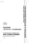
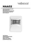
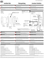
975-0427-01-01 Revision D November 2010
Installation Guide
Montageanleitung
Instructions d’installation
WARNING: Fire hazard
WARNUNG: Brandgefährdung
AVERTISSEMENT : risque d'incendie
Read, follow, and save these instructions to reduce the risk of fire hazard, equipment damage, or
malfunction.
Bitte lesen, befolgen und bewahren Sie die Instruktionen und reduzieren Sie damit die Brandgefahr, einen
Geräteschaden oder die Funktionsstörung.
Veuillez lire, suivre et garder ce manuel d'utilisation pour réduire les risques d'incendie, de dommages à
l'équipement ou de mauvais fonctionnement.
WARNING
WARNUNG
AVERTISSEMENT :
Do not use LinkLITE in connection with life support systems, medical equipment, or where human life or
medical property may be at stake.
Der LinkLITE ist nicht zur Verwendung im Zusammenhang mit Lebenserhaltungssystemen oder sonstigen
medizinischen Anlagen oder Geräten vorgesehen.
Les modèles LinkLITE ne sont pas étudiés pour être branchés sur des appareils de maintien des fonctions
vitales ou d’autres équipements ou appareils médicaux.
Mounting sequence
Montage Folge
Séquence de montage
Battery positive ‘MAIN’ (to load e.g. charger or inverter)
Batterie Pluspol ‘MAIN’ (zu den verbrauchern z.B.
Ladegerät oder Inverter)
Positif batterie ‘MAIN’ (vers utilisations ex. Chargeur /
convertisseur)
Hole diameter 2 1/16" to 2 1/8" (52 - 54mm)
Loch Durchmesser 2 1/16" to 2 1/8" (52 - 54mm)
Trou diamètre 2 1/16" to 2 1/8" (52 - 54mm)
Use enclosed screwdrvier
Benutzen Sie den mit-gelieferten
Schraubendreher
Utilisez le tourne-vis fourni
60V/1A alarm contact
60V/1A Alarm Kontakt
60V/1A contact l'alarme
Not used
Nicht verwendet
Non utilisé
twisted pair verdrilltes Paar
Paire torsadée
Battery negative (system ground)
Batterie Minuspol (Systemerde)
Négatif batterie (- système)
Rubber washer
Gummi Ring
Rondelle en
caoutchouc
Battery monitor
Batteriemonitor
Contrôleur de batterie
Locking nut
Sperr Mutter
Ecrou de blocage
Turn direction for nut locking
Drehrichtung für Muttersperrung
Tournez le sens pour le blocage de l'écrou
Mounting panel
Montage Brett
Panneau de montage
2x1AT fuse
2x1AT Sicherung
2x1AT fusible
1AT fuse
1AT Sicherung
1AT fusible
Battery positive ‘AUX’ (to load e.g. charger
or starter motor)
Batterie Pluspol ‘AUX’ (zu den
Verbrauchern z.B. Ladegerät)
Positif batterie ‘AUX’ (vers utilisations ex.
Chargeur)
Shunt
*
• Make sure the batteries you install are always in good health, preferably fully charged
• Vergewissern Sie sich, dass die von Ihnen eingebauten Batterien in gutem Zustand und am besten
voll aufgeladen sind.
• Assurez-vous que les batteries que vous installez sont toujours saines, de préférence chargées.
Auxiliary battery (optional)*
‘Auxiliary’ Batterie (Optional)*
Batterie ‘Auxiliary’ (optionnelle)*
Main battery*
‘Main’ Batterie*
Batterie ‘Main’*
WARNING: Fire hazard
WARNUNG: Brandgefährdung
AVERTISSEMENT : risque d'incendie
All fuses must be located as close as possible to the battery terminals. Install the fuses only when all other
connections are made and double checked!
Alle Sicherungen muss sich so nah wie möglich an den Batterieanschlüssen befinden. Installieren Sie die
Sicherungen erst dann, wenn alle anderen Anschlüsse verbunden und überprüft wurden!
Tous les fusibles doivent être situés aussi près que possible des bornes de la batterie. Installez les fusibles
uniquement lorsque toutes les autres connections sont faites et que vous les avez à nouveau vérifiées.
WARNING: Fire hazard
WARNUNG: Brandgefährdung
AVERTISSEMENT : risque d'incendie
All thick lines in the above connection diagram, represent the main current lines. These lines must be wired
with a wire type and size which is rated for the maximum battery current. Overcurrent protection for these
lines is not shown and is required. Obey applicable installation codes.
Alle dicken Linien in der obigen Anschlusszeichnung stellen die Hauptstromleitungen dar. Diese Leitungen
müssen mit Kabeln gezogen werden, die mit dem vollen Batteriestrom belastet werden können! Überstromschutz
für diese Linien wird nicht gezeigt und wird angefordert. Befolgen Sie anwendbare Installationscodes.
Toutes les lignes épaisses du diagramme de connexion, représentent les lignes de courant principal. Ces lignes
doivent être câblées avec un type de câble qui peut supporter le courant de la batterie pleine! La protection de
surintensité pour ces lignes n'est pas montrée et est exigée. Obéissez les codes applicables d'installation.
WARNING: Fire hazard
WARNUNG: Brandgefährdung
AVERTISSEMENT : risque d'incendie
All thin lines in the above connection diagram represent wiring to and from the battery monitor. This
wiring must be sized at least No. 24 AWG / 0.2mm2. Maximum wiring length between battery monitor and
shunt is 30 meters.
Alle dünnen Linien (vom und zum Batteriemonitor) in der obigen Anschlusszeichnung stellen Leitungen
dar, die eine Minimal Querschnitt von AWG24/0,2mm2 aufweisen müssen. Die maximale Entfernung
zwischen Batteriemonitor und Shunt beträgt 30 Meter.
Toutes les lignes fines (depuis et vers le moniteur de la batterie) dans le diagramme de connexion ci-dessus,
doivent avoir une épaisseur minimum de AWG24/0.2mm2. La distance maximum entre le moniteur de la
batterie et le shunt est 30 mètres.
CAUTION
ACHTUNG
Mise en garde
The shunt must always be installed into the negative line! Installing the shunt into the positive line may
damage the battery monitor!
Der Shunt mu!ß immer in die negative Hauptversorgungsleitung angebracht werden. Das Anbringen des
Shunts in die positive Leitung kann den Batterie Monitor beschädigen!
Le Shunt doit toujours être installé sur le négatif (câble noir)! Installer le Shunt sur le positif (câble rouge),
endommagerait le contrôleur de batterie!
Important: To avoid large errors in current measurement, always twist the ‘I+’ and ‘I-’ shunt lines.
Connect all wires to the shunt exactly as given in the connection diagram.
Wichtig: Um größeren Fehlern in der Strommessung vorzubeugen, verdrillen Sie die Shuntleitungen „I+“ und „I-“.
Verbinden Sie alle Drähte mit dem Shunt auf genau die Weise, die in der Anschlusszeichnung angegeben wird!
Important : Pour éviter de grosses erreurs de mesure de courant, veuillez toujours tourner les lignes shunt
'I+' et 'I-' Connectez tous les câbles au shunt exactement comme indiqué sur le diagramme de connexion.
Battery monitor connection terminals :
Batterie Monitor Anschlussklemmen :
Raccordement de contrôleur :
positive supply voltage
Plus-Versorgungsspannung
alimentation positif
negative supply voltage
main battery voltage sense input
auxiliary battery voltage sense input
current sense input from shunt (system minus side)
current sense input from shunt (battery minus side)
Minus-Versorgungsspannung
‘Main’ Batteriespannungsfühlereingang
‘Auxiliary’ Batteriespannungsfühlereingang
Stromfühlereingang vom Shunt (’System Minus’ Seite)
Stromfühlereingang vom Shunt (’Battery Minus’ Seite)
alimentation négatif
‘Main’ mesure de tension positif
‘Auxiliary’ mesure de tension positif
mesure de courant du shunt (côté ’System negatif’)
mesrue de courant du shunt (côté ’Battery negatif’)
dry alarm contact (terminal 1) (60Vdc max, to be fused at 1A max)
dry alarm contact (terminal 2) (60Vdc max, to be fused at 1A max)
potentialfreier Alarmkontakt (Anschluss 1) (60Vdc max, Sie müssen
potentialfreier Alarmkontakt (Anschluss 2) fixieren an 1A max.)
contact sec alarme (borne 1) (60Vdc max, vous devez fondre à 1A max.)
contact sec alarme (borne 2) (60Vdc max, vous devez fondre à 1A max.)
Xantrex and Smart choice for power are trademarks of Schneider Electric Services International sprl, registered in the U.S. and other countries. Other trademarks, registered trademarks, and product names are the property of their respective owners and are used herein for identification purposes only. LinkLITE Owner’s Guide © November 2010 Xantrex Technology USA Inc.. All rights reserved.
Unless specifically agreed to in writing, Xantrex Technology USA Inc. (“Xantrex”): (A) MAKES NO WARRANTY AS TO THE ACCURACY, SUFFICIENCY OR SUITABILITY OF ANY TECHNICAL OR OTHER INFORMATION PROVIDED IN ITS MANUALS OR OTHER DOCUMENTATION; (B) ASSUMES NO RESPONSIBILITY OR LIABILITY FOR LOSSES, DAMAGES, COSTS OR EXPENSES, WHETHER SPECIAL, DIRECT, INDIRECT, CONSEQUENTIAL OR INCIDENTAL, WHICH MIGHT ARISE
OUT OF THE USE OF SUCH INFORMATION. THE USE OF ANY SUCH INFORMATION WILL BE ENTIRELY AT THE USER ’S RISK; AND (C) REMINDS YOU THAT IF THIS MANUAL IS IN ANY LANGUAGE OTHER THAN ENGLISH, ALTHOUGH STEPS HAVE BEEN TAKEN TO MAINTAIN THE ACCURACY OF THE TRANSLATION, THE ACCURACY CANNOT BE GUARANTEED. APPROVED XANTREX CONTENT IS CONTAINED WITH THE ENGLISH LANGUAGE VERSION WHICH IS POSTED AT
WWW.XANTREX.COM.
Xantrex and Smart choice for power sont marques de commerce de Schneider Electric Services International sprl. Les autres marques de commerce, marques déposées et noms de produit sont la propriété de leurs propriétaires respectifs et sont utilisés ici dans le seul but d’être identifiés. LinkLITE Manuel d’exploitation © November 2010 Xantrex Technology USA Inc.. Tous droits réservés. Sauf accord écrit explicite, Xantrex Technology USA Inc. (« Xantrex ») (A) NE GARANTIT PAS
QUE LES INFORMATIONS TECHNIQUES OU AUTRES FOURNIES DANS SES MANUELS OU AUTRE DOCUMENTATION SONT EXACTES, EXHAUSTIVES OU APPROPRIÉES; (B)NE SAURAIT ÊTRE TENU RESPONSABLE DES PERTES, DOMMAGES, DES COÛTS OU DES DÉPENSES DE QUELQUE NATURE QUE CE SOIT (SPÉCIAUX, DIRECTS, INDIRECTS, CONSÉCUTIFS OU ACCIDENTELS), QUI POURRAIENT DÉCOULER DE L'UTILISATION DE CES INFORMATIONS; L'UTILISATION DE TOUTE INFORMATION SE FAIT AUX RISQUES
ET PÉRILS DE L'UTILISATEUR; (C)VOUS RAPPELLE QUE SI CE MANUEL EST DANS UNE LANGUE AUTRE QUE L'ANGLAIS, SA PRÉCISION NE PEUT ÊTRE GARANTIE BIEN QUE TOUTES LES MESURES NÉCESSAIRES AIENT ÉTÉ PRISES POUR ASSURER L'EXACTITUDE DE LA TRADUCTION. LE CONTENU APPROUVÉ PAR XANTREX EN VERSION ANGLAISE EST DISPONIBLE SUR LE SITE WWW.XANTREX.COM.
975-0427-01-01 Revision D November 2010
LinkLITE Quick Start Guide
Schnellstartanleitung
Guide de demarrage rapide
This column decribes the absolute minimum number of required steps in
order to setup your Battery Monitor.
Dieser Abschnitt beschreibt alle Installationsschritte, die mindestens
benötigt werden, um Ihren Batteriemonitor einzubauen.
Cette rubrique décrit le nombre minimum absolu des étapes requises pour
installer votre Moniteur de Batterie.
When all fuses are installed, the battery monitor will startup with a blinking display in MAIN battery voltage
readout selection. When pushing one of the three buttons, the LCD stops blinking and you can navigate through
all readout selections using the V, A/Ah and % keys. The battery monitor now operates in the Normal Operating
Mode. The following readout selections can be made :
Main battery voltage.
Main Batteriespannung.
Main batterie tension.
Wenn alle Sicherungen eingebaut sind, geht der Batteriemonitor mit blinkender Anzeige der ‘MAIN’
Batteriespannung an. Wenn Sie eine der drei Tasten betätigen, hört die LCD-Anzeige auf zu blinken und Sie
können mit hilfe der Taste V, A/Ah und % einen Anzeigemodus wählen. Der Batteriemonitor arbeitet nun im
normalen Betriebsmodus. Die Standardanzeigeauswahl wird in folgender Reihenfolge eingestellt :
Auxiliary battery voltage
(optional)
Charge / dischargecurrent. ‘-’
sign represents discharge current.
Auxiliary Batterie spannung
(optional).
Lade- / Entlade strom. Das Minus
zeichen gibt den Entladestrom an.
Courant de charge/ de décharge.
Tension de la batterie auxiliaire
(en option).
Le signe '-' représente le courant
de décharge.
Lorsque tous les fusibles sont installés, le moniteur de la batterie démarrera par un affichage clignotant dans la
sélection de l'affichage de tension de la batterie 'MAIN'. Lorsque vous appuyez sur un des trois boutons, le LCD
s'arrête de clignoter et vous pouvez naviguer dans toutes les sélections d'affichage à l'aide des touches V, A/Ah ou
%. Le moniteur de la batterie fonctionne maintenant sous le Mode d'Opération Normale. La séquence de sélection
d'affichage standard est la suivante :
Amount of consumedAmp-hours.
State-of-charge (SOC) in percent.
Menge der verbrauchten
Amperestunden.
Ladezustand (SOC) in Prozent.
Etat de charge (SOC) en pour-cent.
Quantité d'Ampères heure
consommés.
The display also indicates SYCHRONIZE. As will be further explained in the owner’s manual, this message
means that the battery needs to be fully charged first, in order to synchronize the battery monitor with the battery.
Otherwise, the State-of-charge readout will be invalid. The more often you are fully charging your batteries, the
more precise the battery monitor will indicate all parameters. This will also result in a longer lifetime of your
batteries.
Before the batteries can be fully charged, you first need to adjust or check the following Functions:
Function F01 (Battery capacity), F02 (Charger’s float voltage) and F05 (low battery alarm in Volts).
Setting these Functions to the right values, will in most cases result in a correctly operating battery monitoring
system.
Please follow the instructions in the Owner’s manual on how to adjust or check all Functions.
In der Anzeige erscheint ebenfalls SYNCHRONIZE. Wie in der Bedienungsanleitung genauer erklärt wird,
bedeutet diese Anzeige, dass die Batterie zunächst voll aufgeladen werden muss, um den Batteriemonitor mit der
Batterie zu synchronisieren. Andernfalls ist die Anzeige des Ladezustands ungültig. Je häufiger die Batterien
vollständig aufgeladen werden, desto genauer zeigt der Batteriemonitor alle Parameter an. Außerdem verlängert
dies die Lebensdauer Ihrer Batterien.
Bevor die Batterien allerdings vollständig aufgeladen können, müssen Sie die Funktionen F01 (Nominale
Batteriekapazität), F02 (Erhaltungsstufespannung), und F05 (Niedrigspannungsalarm in Volt) einstellen. Indem
diese Funktionen auf die richtigen Werte eingestellt werden, wird in der Regel sicher gestellt das Ihr
Batteriemonitorsystem einwandfrei funktioniert. Bitte Lesen Sie die Bedienungsanleiung für weiteren
Informationen über Funktionseinstellungen.
L'affichage indique aussi SYCHRONIZE. Comme il sera expliqué plus loin dans le manuel de l'utilisateur, ce
message signifie que la batterie à besoin d'être d'abord complètement chargée afin de synchroniser le moniteur de
batterie et la batterie. Sinon, l'affichage de l'état de charge ne sera pas valide. Plus vous chargez la batterie, plus le
moniteur de batterie indiquera tous les paramètres les plus précis. Cela permettra aussi d'augmenter la durée de
vise de vos batteries.
Cependant, avant de pouvoir charger complètement les batteries, vous devez d'abord régler les Fonctions F01
(capacité nominale de la batterie), F02 (Tension float du chargeur) et F05 (Alarme On batterie faible en Volts). En
réglant ces fonctions aux bonnes valeurs, le système de contrôle de la batterie fonctionnera, dans la plupart des
cas, correctement. Veuillez suivre les instructions du mode d'emploi du propriétaire sur la façon dont ajuster ou
vérifier toutes les Fonctions.
Troubleshooting guideline
Fehlersuche
Guide de pannage
Problem
The monitor doesn't operate (no
display)
Remedy or suggestion
• Check monitor and battery side connections.
• Make sure the inline fuses are installed and not blown.
• Check battery voltage. Battery might be flat. Vbatt must be
>8VDC.
• Try to restart the monitor by removing / placing the fuses again.
Current readout gives wrong polarity • Current sense leads from the shunt are reversed. Check the
(positive current instead of negative
installation guide.
when discharging)
The monitor resets all the time
• Check the wiring for corrosion and / or loose contacts.
• Battery might be flat or defective.
“CHARGE” or “SYNCHRONIZE” • Charge battery full (synchronize your battery with the monitor)
keeps on flashing
• Check the Auto-sync parameters in Functions F02 and F03 for
possible wrong settings.
State-of-charge readout not accurate • Check if all current is flowing through the shunt (the negative
terminal of the battery may only contain the wire going to the
battery-side of the shunt!).
• Current sense leads from the shunt are reversed.
• Check abattery capacity settings (F01)
• Check if battery monitor is synchronized.
Problem
Lösung oder Vorschlag
Der Monitor funktioniert nicht (keine • Überprüfen Sie die Verbindungen von Monitor und Batterie.
Anzeige)
• Stellen Sie sicher, daß die Sicherungen installiert und nicht
durchgebrannt sind.
• Überprüfen Sie die Batteriespannung. Die Batterie könnte leer sein.
Der Wert Vbatt muß 8VDC sein.
• Versuchen Sie, den Monitor erneut einzuschalten, indem Sie die
Sicherungen herausnehmen / wiedereinsetzen.
Stromstärkenanzeige zeigt falsche
• Shuntverkabelung sind falsch gepolt. Sehen Sie noch einmal in die
Polung an (positiv statt negativ beim
Montageanleitung.
Entladen)
Der Monitor stellt sich ständig neu ein • Überpüfen Sie, ob die Verbindungen rostig und/oder lose sind.
• Die Batterie könnte leer oder defekt sein.
Ständig blinkende Anzeige
• Batterie vollständig aufladen (Batterie mit dem Monitor
“CHARGE” oder “SYNCHRONIZE” synchronisieren)
• Überprüfen Sie die Auto-Sync-Parameter in den Funktionen F02
und F03 auf falsche Einstellungen.
Ladezustandsanzeige (%) sind nicht • Prüfen Sie, ob der gesamte Strom durch den Shunt fließt (der
exakt
Minuspol der Batterie darf nur den Draht zur Batterieseite des
Shunts aufnehmen).
• Die Bekabelung vom Shunt sind falsch gepolt.
• Überprüfen Sie die Batteriekapazität Funktion (F01)
• Synchronisieren Sie die Monitor.
Probleme
Solution ou suggestion
Le contrôleur ne
fonctionne pas (pas
d'affichage)
• Vérifiez les branchements entre la batterie et le contrôleur.
• Assurez-vous que les fusibles sont présents et en bon état.
• Vérifiez la tension de la batterie. Elle est peut-être trop basse: Vbatt doit être
>8VDC.
• Essayez de redémarrer le contrôleur en enlevant puis en remettant les fusibles.
Mauvais affichage de la • Inversion des fils de mesure du shunt. Voir instructions d'installation.
polarité du courant
(positif en décharge)
Le contrôleur se remet
• Vérifiez que le câblage est exempt de corrosion et/ou que les contacts sont bien
régulièrement à zéro
serrés.
• La batterie est peut-être totalement déchargée ou défectueuse.
“CHARGE” ou
• Chargez la batterie entièrement (synchroni- sez votre batterie avec le contrôleur)
“SYNCHRONIZE”
• Vérifiez que les Paramètres Auto-sync des Fonctions F02 et F03 sont corrects.
clignote en permanence
Mauvaise indication de • Vérifiez si la totalité du courant passe par le shunt (la borne négative de la batterie
l'état de charge et/ou de
doit comporter uniquement la liaison vers le shunt!).
temps restante
• Inversion des fils de mesure sur le shunt.
• Vérifiez Capacité de la batterie fonction (F01)
• Vérifiez si le contrôleur est synchronisé
Xantrex and Smart choice for power ist eine Marke von Schneider Electric Services International sprl. Andere Marken, eingetragene Marken und Produktbezeichnungen sind Eigentum der jeweiligen Eigentümer und werden in diesem Handbuch lediglich zur eindeutigen Identifikation verwendet. LinkPRO Betriebshandbuch © November 2010 Xantrex Technology USA Inc.. Alle Rechte vorbehalten. WENN NICHT
AUSDRÜCKLICH SCHRIFTLICH FESTGELEGT, TRIFFT FOLGENDES AUF XANTREX TECHNOLOGY USA INC. (IM FOLGENDEN KURZ "XANTREX" GENANNT) ZU. XANTREX: (A) GIBT KEINE GEWÄHRLEISTUNG HINSICHTLICH DER GENAUIGKEIT, VOLLSTÄNDIGKEIT ODER EIGNUNG DER IN DEN HANDBÜCHERN ODER ANDEREN UNTERLAGEN ENTHALTENEN
TECHNISCHEN ODER ANDEREN INFORMATIONEN. (B) ÜBERNIMMT KEINE VERANTWORTUNG ODER HAFTUNG FÜR SICH AUS DER NUTZUNG SOLCHER INFORMATIONEN ERGEBENDE SPEZIELLE, DIREKTE, INDIREKTE, ZUFÄLLIGE ODER FOLGESCHÄDEN, VERLUSTE, KOSTEN ODER AUSGABEN. DIE NUTZUNG DIESER INFORMATIONEN ERFOLGT AUF ALLEINIGE
GEFAHR DES ANWENDERS. (C) WEIST DARAUF HIN, DASS FÜR DIESES HANDBUCH, WENN ES IN EINER ANDEREN SPRACHE ALS ENGLISCH VORLIEGT, ZWAR ALLE SCHRITTE ZUR SICHERSTELLUNG DER GENAUIGKEIT DER ÜBERSETZUNG ERGRIFFEN WURDEN, DIE GENAUIGKEIT ABER NICHT GARANTIERT WERDEN KANN. DER VON XANTREX GENEHMIGTE INHALT
IN ENGLISCHER SPRACHE IST UNTER WWW.XANTREX.COM VERÖFFENTLICHT.