1
REVOX AGORA
B
AKTIVLAUTSPRECHER' Bedienungs- und Serviceanleitung
ACTIVE LOUDSPEAKER ' Operating and Service lnstructions
ENCEINTE ACOUSTIOUE ACTIVE ' Mode d'emploi et instructions de service
TABLE OF CONTENTS
INHALTSVERZEICHN IS
ALLG
EIN ES
,..
]
1.T Kontro e vor dem Anschliessen
..
ansNetz...
1.2 Bedlenlrngselemente .... ..
I 3 Kontro -Leuchteri {LED) ..
2
AIJ FSTFLLI] N G
E I,,4
3.
3T
2
3
4
4
2
ANSCH LU SS AN VORVER
STARKER ODER VEFSIÄFKER 7
Var ante
. 10
l
...
Var ante 2 ((Durchsch eifbetrieb)) I l
Varanle 2 mt
3.4
(BASS BLEND) FlnKtion .
Kettenbetrieb f ür rnehrere
Aktvautsprecher. ....
12
...
E
rsaizTeile
CtNEq^L
2
onu ol
4
4
Checks bef.ire power ng
r. öq_ pr F
C
p
o."ip
(l-D )
! T \C
..
3
5
21
L C NTRA- rS ..
I T Contrö es pr6c6dant e raccor
dörönt dö
"r. 2 Orgd .. d- "ppd,.it
o'l.6."ndF
( tD)
I Vo," . 6- 6.
'2
INSTALLAT ON
..
3.
3
7
3l
11
RACCOF DENi]ENT AU
PREAMPLIFICATEUR OU A
IAMPLIFICATEUR..
TO
32
33
521
522
53
54
BLEND)
ence ntes actives
fonction (BASS
12
..
.12
CARACTERIST OU ES
TECH N
5l
52
1
13
4
512
5't 3
511
515
b
Faccordement en chaine de
5
511
4
4
3.4
a
SPEC F CAT ONS
..
3
. 10
Var ante T...
Var ante 2 ((op6rat on en bouc e)) I l
p usieurs
4
...
2
3.1
12
34
12
13
4
TECHN SCHE DATEN
14
5. SERVTCE ....
... 14
51 Ausbau ..... .....
14
5.1 1 Lautsprecherchass s
14
5T2 Verstärker Einheit.
5 1 3 SW TCH BOARD I 085.272 ... 15
15
5 1.4 AUD|O BOARD 1 085 273
5 1 5 CONNECTOR BOARD 1 OB5 27T 15
5.2 E nste lungen. .....
16
16
5 2 1 Umschaltung 22AV /114V
5.2 2 Ruhestrome nstellung der
16
Le stLrngsverstä rker
Scherna .... ....
... 1f
5.3
54
II
2
REPERTOIRE
OUES ,...
5
SEFVICE
5.1
D6montage.
5.r.1
HaLrt par eLrrs
512
513
.
oc des amp ficateurs
SW TCH BOARD 1 085 272
5.1 .4 AUDIO BOARD 1OB5 273
5.T.5 CONNECTOR BOARD T OB5 271 .
F69lages.
5.2
5.2.1 Comrnutation 22AV I 11OV
522 Rdglage du courant de repos des
5.3
54
B
amplificateurs de puissance ...
Sch6nia ...
P öces d6tach6es
13
4
4
4
4
5
b
5
6
6
WICHTIGE HINWEISE
IN/PORTANT
Schützen S e lhr Gerät vor übermäs-
Protect your
s
ger
den
bea
c
.,,c -nd treL.hligke L Vo
ALtste.len rsl Kapttel 2l'1
hte n.
Verstärker angeschlossen werden
(Kap te 3), die Hinweise lm Kaprte
1.1 (Kontrolle vor dem Anschl essen
ans Netz; srnd unbedingt zu beachten
dspea ker.
Den Geräten, die in der
B u
nd esrep u
llk Deutschland verkauft werden,
llegt eine speziel e Garantleanforde
rungskarte bei. Entweder bef ndet
sich die Karte in der Verpackung,
oder aber lrl einer Plastiktasche an
Ve rpackungsa ussense ite. Sol te
diese Karte fehlen, wenden Sle slch
an lhr REVOX Fachgeschäft oder an
lhre R EVOX-Land esve rtret! ng.
Für n der Schweiz und ln Osterreich
gekaufte Geräte gibt der Fachhänd
ler die Garant ebescheinigung ab.
Bei den in Frankre ch gekauften Ge
rdter ' nde^ S'e dre Gara lreka te .n
der Verpackung. Dlese Karte muss
von Lhrem autorisierten REVOXFachhändler vol ständig ausgefül t
und unte rsch rieben werden.
Bitte beduhLen Sre da's d e Gara-L e
nur im Verkaufsland gü iig ist. Ausserdem machen wir Sie darauf auf
merksam, dass die Ga ra ntie erlischt.
wenn am G erät u nsa chgemässe Ein
gr ffe oder nicht fachm ä nn ische Reparaturen vorgenommen worden
sind.
der
VERPACKUNG
Bewahren Sie die Originalverpak
.r,ng au! Bet e'er lran.Po-L i.t
diese S pezia lverpac ku ng der beste
Schu.z lu' .hr wertvo la. Gerä1.
Sub ect to change.
Pr nted ln SwLtzer and
bvW LL STUDERAG 10 30.0190(Ed 0684)
Copyright by W LL STUDER AG
CH 8105 Regensdorf-Zur ch
GUARANTEE
A spec a guarantee
request card ls
the packing or in a plastic pouch on
the outs de of the packing. Shou d
th s card be miss ng. please consu t
your REVOX dealer or your nationa
d
istrib uto
r.
Guarantee cards for equlpment so d
^
Sw LTe
d-d a-d A rs a dra
rs-
sued d rect y by the authorized dea
er
Guarantee ca rds for equlpment so Ld
n
pa
connect6es au (p16 )amp ificateur
avant d ötre raccord6es au secteur
\vo r chapitre 31. A cale-let. I esl n pöratif de suivre es directives du
chapitre 1.1, rContröles p16c6dant e
raccordement de l'appareil au sec
teunI
GARANTIE
bypacked to a I equlpment so d
within the Federal Republlc of Ger
manv. Th s is either located lnside
REVOX
Prot6gez votre appareil de l'humidide a chaleur excessive. Veulllez
ire attentivement le chapitre 2 avant
d'installer 'ap pa rei
Les enceintes actives do vent ötre
t6 et
.
The active loudspeaker should be
connected to the (pre)ampllf er
p Ap powe i>
1S^c r on 31 belo
switched on. Observe the instruc
tions in Section'l 1. "Checks before
powerino the equ pment"l
I
GARANTIE
b
eq ulp m ent from exces
sive heat and humidity. Read Sec
tlon 2 before installrng the active
ou
Vor dem Ansch iessen ans Netz so ll
te der Aktlvla utsp reche r am (Vor-)
AVIS IN/PORTANT
France are ocated inside the
cking. Th s card must be comple
tely fiLled out and s gned by your
arlhorized REVOX dealer.
P ease note that the guarantee is on-
y valid within the country in whlch
the equipment has been sold. The
guarantee becomes nuLl and vo d f
unauthorlzed modif ications or unprofessional repairs are made.
Pour les appareils vendus en BIA.
vous trouverez so t ä I'int6rleur de
Iemballage soit dans une pochette
en plastique fix6e ä I'ext6rieur. un
lo ru aire de deronde de ga-anL o.
Si ce dern er devait manquer, votre
fourn sseur ou l'agent officie RE
VOX du pays o'a"ha. >e [P'a t '
plars r de vous la procurer. Veuil ez
rempl jr düment ce forrnulaire et'en
voyer ä I ag ence off lc ielle REVOX du
pays d'achat.
Pour 1es appare ls achetdes en S!!!
se ou en Autriche. 'attestation de
garantie est d6l vree par ie revendeur REVOX autoris6.
Po u r
les
a
ppa rells vend us en Fra nce,
vous trouverez a carte de garantie ä
I'int6rieur de Iemballage. Cette car
te do t ötre complötee et s gn6e par
votre revend eur REVOX agr6e.
La garantie n'est va able que dans le
pays oü a lieu l'achat. Nous nous
permettons de vous rendre attentlf
au fa it que toute interventio n non au
torisöe ä l' nt6rieur de I appareil,
nous llböre de toute obl gation.
PACKING
EMBALLAGE
P ea se save the o rig ina I packing ma
Conservez l'emballage d'or g ine.
Dans e cas d un iransport, il est la
me lleure protection pour votre ap-
terial because its special construction provides opt mum prolection
for your valuab e equipment.
pa
rei
.
1. ALLGEMEINES
1. GENERAL
1 GENERALITES
Be konvent onel en. päss ven Lautsprechern er[olgt d e Aufte lung des Fre
querzbereichs auf die einze fen Laut
sprecherchasss durch passve Fi ter,
n cofveftiofal, passive speakers, the
frequency range is divided arnong the
Dans es efcelntes passves conven
t onfelles, e signaL est divis6 en p ages
die mit Spulen und Kondensatorelr auf
gebaut sind Der 0 h m'sche Wid e rsta nd.
m t dem diese S pulen behaftet sind, und
auch derjen ge des Verblndungskabe s
zw schen Verstärker und Lautsprecher,
wirkt sich versch echternd auf den
Dämpfungsfaktor aus, das he sst, die
Kontrol e des Verstärkers über d e Mem
branbewegungen der Lautsprecher
wird erschwert
Bel aktlvef Lautsprecherr ertolgt d e
Aufte iung
des Frequenzbereichs vor
den Lelstu|rgsverslärkern. Sle kann dort
verlust os m t akt ven Baue e.fenten
(Verstärkern) ausgeführt werden. Dem
T ef , dem N,/l ttel und dem lochtonbe
ch st je
geordnet.
re
sind m
-o
n Leistungsverstärker
D
ese
zu
Le stu ngsve rstä rke r
Lautsprechergehäuse enge
baut lda her die Bezeic hnu ng
(a
kt v)). Es
ergeben sich kurze. sehr verlustarme
Verbindungen zw schef den Le stungs-
verstdrkern und den entsprechenden
Lau Lspreche rcha ss s Der Dämpfungs-
faktor st bekannt und kontrol ierbar
/o l ld ll P' L'"I \'\o ,. 1 o q'rrö
nen ene asymmetrsche Ausenkung
der Membran auf Das he sst. di,^
Schw ngspu e bewegt sich n R chtung
zum Magneten hln nlcht gle ch wie vorl
hm weg. Die Membranen von T efton
autsprechern vol führen de grössten
Aus enkungen, deshalb kommt d ese
Asymmetr e be Tieftonlautspreche rn
am stärksten zum Ausdruck. Beim Aktiv
i" . .or., , 6,
B !1 I d orp . I g
^coc^
mög iche Lösung
dieses Prob ems angewandt, der sogenanfte (Push Pu l)
Betr eb von zwe gle chen Tjefton aut
sprecherf, von denen der eine auf her
kömrn iche Art, der andere jedoch mlt
d-l V"gn.t
l^-rr
-d, ar ö
^^
send, m Gehäuse mortiert ist Auf diese
Weise kompensieren s ch d e Asymme
trien der LaL.rtsprecher gegense tig Die
N/embranbewegung der beidef T efton
autsprecher
st durch eine akt ve
Zwangssteuerung starr mit dem Aus
gangssigfal des T efto nve rstä rke rs ge
koppe t. Frequenzgangfehler und N,4 t
schw fgef von Gehäuseresonanzen hö
herer Ordnung, w e sie bei pass ven und
aktiven Systemen ohne Zwangssteu erufg auftreten, gehören der Vergangen
he t an. Zur akust schef Unterstützung
der extremen T efen. bel defer der La ut-
sprecher einen verringerten W rkungs
grad aufweist, dient das ä s He mholtzResonator ausqebi dete G ehäuse
rdrd."r 'Pöatö,1". ." b,P". \^
f lters imp emented w th co ls and capac tors The ohmlc res stance inherent to
these co Ls and oI lhe cofnect ng cable
between the ampl fler and the speaker
" fF, th.do1 o 9',r o ia
it becomes more dlff cult to contro the
odr.
."1.
diaphragm osc; ations of the speaker
through the amp f er.
n äctve loLrdspeakers, the frequency
range s d v ded before the power amp l
f ers. lt can be lmpLernented with oss
free active componerts {anrp fers).
One power amp if er each s assigned to
the bass, med um, and treble frequency
d Cta hö.p po,^öt o1 p ar .e.l
talled n the speaker cabinet (hence the
designatlon "active') Very short, ow
oss connectons between the power
amp ifiers and the corresponding
speaker chass ses can thus be estab,. öd . .. F tr. ddnp, g 'd o
knowf, it can be contro led
The d aphragm disp acernent of cone
type loudspeakers s gene ra I y asymmetrica . i.e. the moverneft of the vo ce co
toward the magnet s not the same as
the movement away from t S nce the
woofer's d aphragms perform the larI
L a.. rr-16 ,
q- td p" o-.rp
a so most pronounced in thls type ol
loudspeaker. n the actve loudspeaker
AGORA B. the or y feasib e so ution to
this prob em has beef mp emented. the
insta lation I the speaker cab fetoftwo
identca woofers operatng n "push
pull' mode, e. one is rrourted conveftlonal V, the other has ts magnet svstern
fac f g outward The a sVm m etries of the
speakers thus compensate each otlrer
The d aphragm movement of the two
speakers s r gdy coupied to the bass
ampl f er output s gna by actlve forced
cortrol. Frequency response errors and
'g' od"i "b ^r.od 6o ,r g
I passive and
actlve syslems without
forced contro are now ä th ng of the
past. The cab fet wh ch is des gned as a
Helmho tz resonator acoustica ly sup
ports extrem ly low frequenc es at which
the speaker effic ency is lower.
dö'pq ta ö pd oF | - po .t[ -d
lses ä l'a de de condensateurs et d'ln
ductances. La rösistance ohmique de
^ d. t"..^ lbobi-dg^ I " q-"
I mp6dance des cäbles de l aisof
entre
'amp if cateur et les haut par eurs d minuent le facteur d amortissement. c est
ä dire. le contröle du d6placement des
membranes des haut par eurs par I'am
p if cateur est r6duit.
DoLt ö ö. on. o l.Ä o tÄp.r. Oi
du signa s effectue en amont des amp i
. d- p-r
anua pa
de
'-
"tact fs qui excluert toute perte de s gna
A chaque
p age de fr6querces, grave,
mddium et a gu, est associ6 un amp iti
cateur de pulssance d stinct, mort6
dans I'encente (d'oü a ddnominaton
(act ve)). Ceci permet des ia sors cour
tes ä trös fa bles pertes entre les amp i
f cateurs et les haut par eurs correspon
dants Le facteur d amortissement est
a ors sauvegard6.
ldlongatlor des membranes des haut
par eurs d cöne presente g6n6ra ement
des dissym6trles. La bobine mobile ne
'.
d^pld,
- p". d.
a
n-r " [a o .,
vant qu'elle s 6carte ou se rapproche de
'a mant moteur. Cette dissym6trie est
plus importante pour es haut parleurs
de grave dont les membranes subissent
l.
Ol
r grard". o.
L-
on lotr Fnö
active AGORA B a recours ä aseueso
ution possib e . efirploi de deux haut'
parleurs de grave semb ab es en mode
D.. l D.l. Ln
^ i ^o r^ d^ .r o.t
usue le dans erceintetandisque 'autre
a son aimanl or ente vers l'ext6r eur Ce
montage permet la compensaton mutue e des dissym6tries des deux haut
par eurs. Le dep acement des membra
nes de ces deux haut parleurs est parfä
tement coftrö 6 par une com ma nde for
a- d- o1 o rlr o'^ r O
",e l" | ^gL
arlt6s de la 16ponse en fr6quence et ies
r6sonarces aux freq!rences cr t ques du
boiter apparaissant souvent dans les
i: önö
I d t ^,
tpd ta
on ^", d^ 'or o- .o. I d. . p ob ^nqropod ö'l.ö Lda o r"i ., p" a
,
Le renforcement acoustique aux fr6
ou-r ,- o A b",ö ard JF.por
la conformat on en rdsonateur de Ne m
hoilz dLr hoiller de Ienc-o nte
D e E ngangsempJind ichkeit des Akt v
autsprechers AG0RA B ist umschalt
ba r. so da ss
e r
sowohl
an
Vorverstä rkern
L.O I - .O.- t;-..Orton"lo e
(z B. REVOX 8252. REVOX 8739) a s
auch an Vo verstärkern (z B REVOX
8251) angesch ossen werden kanr. Be
verschiedenen Vol verstärkern und Re
ceivern st e ne Trennung zwischen Vor
verstärkerte
I und Leistungsverstärker
8780) DerAk
t v autsprecher AGORA B karf am Vo[verstärkerte des betreffenden Gerätes
angesch ossen werden Auch der d r-^k
tei moglch
(2. B. BEVOX
Arsc h uss an Ouel engeräte mitvar ab em Ausgangspegel, w e z B. den FM
Turer REVOX 826T oder den CD Plat
tenspie er BEVOX 8225, st durchäus
te
den kba
r.
Der Akt v autsprecher AGORA B harmo
I ert
selbslverständ
lch auch rnit RE
en. hr
The nput sens tiv ty of the äctive oudspeaker AGORA B s sw tch selectable
wh ch means that t caf be connected
not only to preampllfiers and tuner,i
preamp f er combinat ons (e.g REVOX
8252. REVOX 8739), bLrt a so to ntegrated amp if ers (e g. REVOX 8251). n
some of the ampl flers and receivers the
slgna path between the PreamP fer
^.o
Öt - lo
REVOX 8780). The
d o öpo\i\Ö o^p
can be opened (e
g
äctve loudspeaker caf then be cor
nected to the preamp if er sect on of the
correspond
rg uf t
D
rect connect orl
to source un ts wilh variable output leve
- o l"c 'O\
B2o
F\,4
o "
REVOX 8225 CD Player is a so feas ble
The actve oLrdspeaker AGORA B is of
course a so compat ble with pr or g-ane
rat on REVOX equ pment. Your dea er
w I glad y adv se Vou.
VOX Geräten aL.rs f ruheren Ser
Fachhänd er weiss Bat
La sensib llt6 d entröe de 'enceinte act
ve AGORA B est commutable. E le Peut
donc ötie auss ben raccord6e ä des
pr.o-rp
dto.
or o oö
sortie ajustab e, cornme par exemp e e
tun,^r N/F REVOX 8261 ou le ecteur CD
REVOX 8225, est en outre possible
B en entendu, 'ence nte actlve AG0RA
ö po dtöta1o,a
B ". oo"".
es appare s REVOX des s6r es an
tÖrieures. Votre revendeur speclalls-6
avec
.or..-rl-
qr-"1^
d "lo
CESSA TES
fqebaule Schutzscha tungen verh ndern, dass weder d e eingebauten Le
stungsverstärker durch Uberhitzurg
l.loch der N4 ttel und der Hochton aut
sprecher du rch Überastung Schaden
E
nehmen können.
m Automat kbetr eb wird der Aktiv aut
p.- -. auoq^ B , ror , r , -
g-
schaltet, sobä d e n E ngangssigna vor'
handen st Wenn während ca 5 M nu
ten ke
I
Eingangss gfalvorhanden war,
w rd er automatisch ausgeschaltet
((Stand by). Bereltschaft) Der Strom
verbrauch im (Sland by) Betrleb st verna
Bui
t-ln circuits prolect the ntegrated
power amp f ers from overheating and
the mldrafge speaker and the tweeter
from overloa ds
ln automatc mode, the active oud
speäker AGORA B s automatica y
sw tched on as soon as an nput signa s
avä ab e Lt s swtched off (stand by) it
no s
gna
s ava lable for approxlmate
V
5 minutes Power consumpt on n stand
by niode s neg igib e
The autornat c on/off c rcu t can be d sa
bed (actlve speaker ether always
sw tched on or off)
chlässlg ba r geflng.
orrb "'-
sons tu fer/p16a m pl flcateur (par ex FE
VOX 8252, REVOX 8739) qu'ä des aropl f cateurs ft6g16s (par ex BEVOX
8251) Dans e cas de certaif s ampl ficara. .a a.p ,r il6qa
^. oo
b e de s6parer le bloc prÖarnpl f cateur
des 6tages de puissance (par ex. REVOX
B7B0) Lence nte act ve AGORA B Peut
alors etre raccord6e au b oc p16ampl fl
cateur de ce type d apparel . Le raccor
dement d recl ä des sources ä nlveau de
.
tL oöpol-
lO,
"
laoo p.
v ennent Les ampLificateurs de pu ssan
ce contre tout Öchauffernent excessif et
protögent es haut parleurs de m6dlum
et d a gu conlre les surchärges
o..a-rön o..o ro, j.ö dr
I erce fte acoustique
öl o ao|o.ä
qrörö. d^ q
s gna est pr6sent ä entr6e Si aucun-.
lt.lo..
se so us tens on de
I
modulation n Lntervleft p us pendant
minutes, 'enceinte acoust
qL.re
5
se de
c enche d e le möme ((Stand by), mode
ve I e). La consommätiof de co!rant deD, äoi looÄ. önl -.9 igödb
Le systöme de m se en/'hors tens on au
tomatque peut 6tre rnis hors fonctou
Dle Ein /Ausschaltautomatik kann aus
ser Betrieb gesetzt werden (Aktvlaut
(l'ence nte active peut a ors ötre en /d6
c enchee au qr6 de uti sateur)
sprecher nach Wahl immer ein- bzw
ausgesc ha tet).
Kontrolle vor dem Anschliessen
1.1
ans Netz
Vor d-.m Ansch iessen äns Netz st zu
überprüfen, ob d e ört che Netzspan
furg mit dem aul dem Typensch ld des
a o . o.- no ä gagöbanör sod
, g\^-
s1
mmt
an
l0od- 220Vot .b^"i
Fa ls nicht, wenden Sie s ch b tte
hren Fa chhä nd er
Der Akt vlautsprecher AGORA B darf
glq! ans Netz angesch ossen werden,
wenf der Anschluss an den Vorverstär
ker oderVerstärk-^f erfolgt ist (Kap te 3)l
1.1
Checks before powering the
Before the speaker s connected to the
AC supply, ensure that the local I ne vo
tage matches the spec f cat ons of the
nafne p ate of the actlve oudspeaker
('110 or 220 V). P ease consu lt you r dea
er f th s s not the case
L
llp " r.^ ojo p.d ö a\roq^ B o
be connected to the preatop ifier or am
p fler before connecting t to the AC
s!pply (Sect on 3)l
Contröles pr6cedent le raccordement de l'appareil au secteur
Avart de proc6der au raccordement au
secteur, on s assurera que a tenslon lo
1.1
equipment
ca e du secteLrr corresponde ä la va eur
de tensio|r nom nale (T10 ou 220V) ndi
qu6e sur la p aquette de r6ference de
'ercelnte act ve.
'en.-o nle aclive AGORA B ne do t etre
raccord6 au secteur que quänd el e est
aaö.o
a o.o.P.r
o I r-6. o
'ampllf icateur (voir chapitre 3)l
o
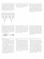
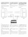
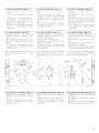
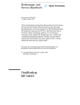
1.2 Bedienungselemente
1.2 Controls
?
l
T
T
oG)
TT
? ?
. '.j-.'.i":i<:-""Li:"
i
I
"@ 6)"
. t(9, @,
Fig
I
OOQJO
o
1
t1l Netzansch uss
t2l Eingangsbuchsen
(L:
I
nker Kanal, R = rechter Kana
)
gangsempfindLichkeit an den
steuernden Verstä rker
t5l Bass-K angste ler
t6l Höhen-K angste ler
l1) E ngangswah schalter. Wäh scha
ter für <BASS BLENDT'Funkt on
tBl Wa h lscha ter für Ein-/Ausschalt
AuTomat
Ftg
2
lll
l2l
Power cofnectiorl
)
t3l Ausgangsbuchsen
(L = llnker Kanal, R = rechler Kana
l4l U'nscL d ter - A'oo' --g d.r F
k
l3l
l4l
[5]
l6l
[7]
[B]
1.3 Kontroll-Leuchten (LEDs)
D e beiden LEDs befinden sich auf der
Scha
llwand, rechts vom Hochtonlaut
sprecher, und sind auch be aufgesetzter
Frontabdeckung s chtbar
e rote LED euchtet, wenn der Aktiv
o-l>O prl pr
".r \o1. dnges6- o .a i>t
ufd der Schalter
lBl
- n Ste lung (OFF) steht, oder
Ste
lung
1.3
schaltet lst.
Die grüne LED euchtet m Normalbetrieb, wenn der Scha ter l8l
- in Stel ung {ON) steht. oder
steht, und der
Lautsprecher durch
dle
scha lta utomatik eingescha
:
eft hand channe.
R = rlght hafd chaf n-" )
O
utput sockets
(L:
eft hand channel.
R = right hand channe
Selector sw tch for match ng the
lnput sens t vity to the dr ving
Eln-/Aus
tet
ist.
Die rote Urul die grune LED euchten,
wenn de e ngeba.ute Schutzschaltung
entweder wegen U bertemperatur oder
wegen Uber astung des I och- oder des
N/l ttelton autsprechers angesprochen
hat lm ersten Fal sind die Leistungsver
stärker stummgescha tet, bis deren
Ten"rperatur auf e nen zu ässigen Wert
gesunken ist, m zweiten Fal w rd d e
Stummscha tung nach einigen Sekunden wieder aufgehoben.
l2l
Pr ses d'entree
I3l
R: canal droit)
Pr ses de sortle
(L : cana gauche.
)
14)
lnput se ector, selector swltch for
"BASS BLEN D " function
Selector switch for automatic
on/off circuit
Pilot lamps
-r o r^d LtD
i
up
en/hors tension automatlque
1.3 Voyants de
wa- h- ä. ivF
speaker s connected to the AC supply
and the se ector sw tch IB] is either
in the "OFF" pos t on, or
in the "AUTO"
R = canal droit)
Com mutateu r pour Iadaptation de
a fonction <BASS B LEN Dr
tBl Selecteur du systdme de mise
(LE Ds)
gl
(L = cana gauche.
a sensibi it6 d'entree ä 'ampl fi
cateur de commande
t5l Contrö e de la tona it6 du grave
t6l Contrö e de la tonalit6 de 'a gu
J) S6lecteur d entr6e, selecteur pour
ampi f ler
Bass control
Treb e contro
ic baffle. to the right of the tweeter, and
a ^ I " b " ö\6n v\l pn tL p ['or o\er i
Lautsprecher durch die Ein-/Aus
schaltautomatk auf (Stand by) ge
- in Stel ung <AUTOT
(L
The two LEDs are ocated on the acoust
steht, und der
TAUTOT
I1l Raccordement au secteur
lnput socket
insta ed.
D
n
1.2 Organes de commande
posltior and the speak
er has been switched to stand by
nodc by l' o dLro-ral o o'f r.ui
.
The green LED I ghts up in normalopera
tion, when se ector sw tch l8l s either
in the "ON" posit on, or
in the "AUTO" pos t on and the speaker has been sw tched on by the auto
rnat c on/off c fcu t.
Both the red !I]dthe green LED are on lf
-
the bullt-n protection circut has re
po d-d. ha b,. du). o ^y ö./r\^
temperature or over oad ng of the rf id-a qFo|r6bl6 .pFd Fr. nthe'..r.rtJa
t on, the power amp if ers are muted un
t ltheir temperature drops to an adm s
'h..-, ono. ". e ^ Ll gi^
-tb a p\cance led aJter a few seconds.
contröle (LED)
Les deux LEDs sont s tu6es sur ie pan
nea u ava nt, ä d ro te du ha ut-pa rleu r d a i
g!
El es demeurent vis bles lorsque
cache en t ssu est en p ace.
La LED rouge
e
s'llum ne si I ence nte ac
tlve est raccordee au secteur et s le s-6
Lecteur l8l est soit
en posltion (OFF).
- en position rAUTOr, 'ence nte active
6taft commut6e en mode (Stand by)
par le systdme de mise en/hors ten
slon a utomatique.
La LED verte s l um ne lors du fonctrof
nement normal, lorsque le selecteur [B]
est so t
-
en pos tlon (ON),
ö^ po.
Uo' AU O . ' c-, |.tnlö äu.t\e
6tant rnise sous tens on par e systör"rd d6
q
r'r p 6- f,O b ll.
O d lto-at,
ue.
Les LEDs rouqe cI verte s'il um inent si le
c rcuit de protection nt6gre est entr6 en
lonction af n de pr6ven r un 6chauffe
ment excessif ou b en une surcharge
des haut par eurs de m6dium ou d'a gu.
Dans le premier cas, e slgnal d'entree
des amp if cateurs de pu ssance est annul6 jusqu'ä ce qu'une temp6rature acceptab e soit atte nte. Dans 'autre alter
ndt \e F<.ig-a d'an FA.\r e.abl
"pläque ques secondes.
2
2
AUFSTELLUNG
B st a s
Standbox konzipert Er so te deshalb
aussch essllch auf dem FLrssboden stehend betr eben werden. Andernfa ls
können Bee fträchtigungen des Klang
Der Aktvlautsprecher AGORA
b
ds auftrete1.l.
e
Le
chers
The active loudspeaker AGORA B is de
s gned as a f oor type box, ie t should
always be insta led d rect y on the f oor
Other slt ngs can adversely affect the
sound mpress on
The power ärnp lfiers are ocated on tlre
stullgsverstärker befinden sich
an der Rückwand des Aktiv autspre
D
rker
erzeugerl
Wärme Damit deren Uberh tzung und
damit e I Ansprechen der Schutzscha
Lelstu ngsverstä
turg verm eden w rd, darf die Zrrkrl
a
tlon der K ühl uft I cht behindertwerdef.
lnsbesordere lst ein min maler Abstand
von 5 bis 10 cm zu r Wand hinter dem Akt v autsprecher e nzuhaltef
D-. I o. ^. t-lr .q o h o oin.
Wand (mlndestens
5 bls 10 cm) ode r gar
in e rer Raumecke kann der Tiefton
bereich unnatür ch überbetont werdef.
Diese unerwünschte Frequenzgang
Überhöhung kanf mit dem BASS
Klangstel er l5l korr g ert werden:
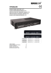
AktivLa utsprecher
Poston0
fre im
rear palre ol the act v-^ speaker. PoweI
ampl fie[s gen(]rate heat C rculation of
the coo ing shou d fol be restr cted n
order to prevent overheating älld conse
qr^ l) ''rul rgb, h.p ot^. o i,.r
L- o i.he ed"ne
bF/.-
speaker and the wal beh rd it sho u d be
at least 5 to 10 cm 12 - 4 inches).
f lhe box s nstä led d rectly in front of a
wal (m n. c earance 5 10 cm) or I the
corner of a room. the bass range can b-o
unnatura ly accentuated This unde
s red frequency response
A I ö p6a'^. tt
tion -2
Raumr
Pos
on
2
Poston
4
oder
r
e ner Raumecke
6
D.r , d. Fg.n rd'rFn d- Pord
j
rnes w rd der Hochtof Ante ldes K ang
bl ds bee fflusst. Der Akt v autsprecher
AGORA B ist so ausge egt, dass s ch in
o-r hLnn trLh rob e.e- WoL ä,
men eln inearer FreqL.renzgang e rstel t.
Mit dem Flöhen Klangstej er l6l kanf
der Hochton Anleil varlLert werden Bel
dieser E nste ung sol te man s ch vorn
e
on ol '^dl
Active speaker ln a Toorn corner
Akt vlautsprecher
Posit
car be cor
rect-.d wlth the BASS contro I 5l:
Act ve speaker free standifg
Position 0
Akt vlautsprecher vor eine r Wand:
Poston
2
SITING
genen Geschmack elten lassen
g t, dass n einem durch
-4or
ng rooms The treb e content can be ad
lusted with the treble contro l6l The ad
lustrnent ls a matter of persoral prefer
erce. As a ru e, the treb e control car be
p lo 0 ,lh'n
Poo
ta ed I a conve|t ona ly furnished Liv
ing room. n roorns w th greater sound
absorpt on (e.g. m !ch upholstered furnl
ture, tapestry, suspended ce I ng with
Höhen K angstel
styrofoarn panels) it may be desirab e to
b eiben kann.
Därfrpfung
er [6] in Posit on rOr
ln Räumen mit grosser
B.
(-2) oder auch
{
vie
e
Polstermöbel.
Wa ndteppiche, abgehängte Decke aus
Styroporp atten) kann eine Anhebung
oe rlo nton-Antetls etwur st Leir
Höhen-K angstel er [6] n Pos t on (+2)
n Räumen rnit kle ner Dämpfung (sehr
wenlg Möbe , v e Glas) kann der Hoch
tor Anteil abgesenkt (verringerL) wer
Do il o
d-- -oh. l"rg t" .
(z
4).
Grundsätz ich so te leder Lautsprecher
so aufgestel t werden, dass er aus dern
akustischen ha rten (schwach gedämpf
ten) Te I des Raums n den akustischen
welchen (stärker. ctedämpften)
stra
h
lt
Tei
boost the treb e bV sett ng the treble
contro to the positiorr "+2". n rooms
witlr ow sound absorptlon (very ittle
furn ture. much g ass), the treb e can be
deemphasized by tu rning the treb e con
tro to the posit on
Les amp fcateurs de pulssafce sont
montös au dos de 'ence nte active
. n^ o. e ..r- p 11 6.o_s . l. pr_i.
sance, ils produiseft un certain d ögage
ment de chaleur Uf volume d'air suffi
sant ä eur refroidissement dot donc
pouvo r c rculer I bremenl af n d'6viter
des excursions de tempdrature qui d6clefcheraert Iacton des crc!ts de
protection On ve lera en part cul er ä
malntenir une distance m n rna e de 5
T
0 cm entre le
d
os de I enceln te et le in ur.
Le posltionnemeft de enceinte acous
t que dlrectement devaft un mur (mln.
5 10 cm) ou b en möme dans un angle
de a piöce d 6coute peut provoquer uf
renflernent art flcie du regjstre grave Le
contrö e de ä tona it6 du grave l5l permet de rem6d er ä cet r'rconvenlert
Enceinte act ve loin d'un mur
Enceinte actlve devant un mur
schnittlich möb erten Wohrräum der
Grundsätzl ch
fence nte act ve AGORA B est con9ue
. Ä t- Ul i--F or- -a Inö ^ .öi-lö
colonne E le do t dorc mp6rat vement
Ät-po -a . ..ol ,ö an.q..O ro.
ga o ot^ po . td I etr. d.tö. orÄp.
po
poston0
6
The character stic of the lsten ng roorn
nflu,-nces the treble content of the
sound impress on. The active loud
spea <er AGORA B is designed in sLrch a
way that a inear lrequency respollse s
atta ned in convent ona y furnlshed lv
't
INSTALLATION
' 2
or even
-4
.
As a ru e, each oudspeaker shouLd be
nstal ed in such a way that t rädlates
from the acoustica ly hard (ow sound
absorpton) area of the room into the
acoustica ly soft (strorg absorpton)
ar-oa of the room
poston
:
2
Ence nte active dans un ang e
pos
tlon
4
ou
6
Les caract6rist ques du oca e d 6coute
inf uent sur la part e a gue de l'ima ge so
nore Lerceinte actve AGORA B
est
concue pour avoir une 16ponse en fr6
quence inaire
da ns une
p öce
m
orsqu'e1
e est
utllsee
oyennement meu b 6e
Le contrö e de a tona ite de aigu 16l
permet d'effectuer les adaptations vou
lues Ce 169lage do t Ctre effectu6 en te
nant seu compte de sa propre sens b ite d'6coute En rdgle g-6n6rale, le contrö
e de la tofa it6 de 'a gu l6l peut rester
en position r0r orsque 'ence nte estplä
c6e dans une p öce m oyennement meu
b öe. Dans le cas de locaux pr6sentant
une forte att6nuation (divans, rnoquet
tes, revötements muraux en styropor,
ö .u örp.önÄ dr ."oud. age
peut otre souhaltab e coftrÖ e de la to
na it6 de I alg u f 6l en posit on (+2). Dans
e cas de ocaux trÖs peu arnortis (trös
peu de meubles, beaucoup de verre), on
peut d minuer le n veau des a gus:con
'o.dö ato äl .d^ .rg.ol( 2) ou merne (-4)
po
tlon
Une bonre rög e cons ste ä nsta ler cha
o o'ö
LF,d oL.q.Fd-ta
qL^l^ o,o öoLl Fod 6dFldoö.ö
acoustiquement ldure) (faiblernent
o i^) ,. ,^ p"rta o o..rio,o"1
rnent (la b e) (fortement amortie).
The actlve loudspeaker AGORA B has
nen überdurchschn ltlich grossen Abstrahlwinke. deshalb isl eine zum Hörer
[enceinte active AGORA B possdde
an exceptionally large radiation angle. lt
is, therefore, not necessary to point the
hin angewinkelte Aufstellung nichl not
wendig.
box at an angle toward the lstener.
rayonnement acoustique rema rquab e.
- asl donr pas -ece\sai a de es otien
ter pr6c s6ment vers uf lieu d'6coute
Starkes Anheben von hohen und tiefen
Frequenzen am (Vor )Verstärker ist für
Lautsprecherwiedergabe ganz allgemein n cht zu empfehien, we I dadurch
d e Vprze'rungswerte J ^|.örq ä.s lerqe
und die Belastbarkeit (im Spezialfa ldes
Strong accentuatlon of high and low fre
quenc es on the (pre)amp if er is gene-
Der Aktiv autsprecher AGORA B hat ei-
die Ansprech
schwe le der Schutzschaltung) stark reduz ert wird. REVOX Lautsprecher sind
Aktivlautsprechers
klangneutra ausge egt und kommen
da her in der Regel
ohne Korrekluren aus.
p
rallv not recommended for speaker re
production because this conslderably
increases the dlstortion and decreases
the power handl ng capacity lthe re-ponse hr^sho d of rhc prolec lio' ci
cuit in the special case of an act ve loud
speaker). REVOX loudspeakers are neu-
trai soundlng and as a rule require no
correct on.
un
rivil6g i6.
I est g6n6ralement plulöt deconseil 6
de re ever trop {ortement le niveau des
aigus et des graves ä parlir du (p16-)amplificateur. D une part, ceci augmente
lnutilement le taux de distorsion et d'au
tre pa rt, ce a red u it sens blement la ma r
ge dynamique du systöme (le seulld'activation des circuits de protection dans
le cas particulier des enceintes actives).
Les haut-par eurs REVOX sont conQus
pour offrir une restitution neutre et peu
vent donc, en rögle g6n6rale, fonctionner sans qu'il soit n6cessaire d effectuer
des corrections.
3
3
ANSCHLUSS AN
oDER vERSrÄRrrR
Vor dem Af schlessen muss d e Ein
gangsempf ndlchkeit d-^s Aktiv aut
sprechers AGOBA B an den steuernderl
Verstä rker arigepasst werden
Wenf es srch um e nen Vol verstärke'
hande t (z.B FIEVOX 825]). muss der
sein
l4l -gedruckt
Do^ö
D\^o Alv1D
-
A-p
(S1el Lrng
t6 =
o
stu ngsverstä rker)
Wenf es s ch um e nen Vorverstätker
e fe Tuner/Vorverstärket
on ((lPrecciver)) haIde t
iz B REVOX 8252, BEVOX 8739)därf
aß 4 ' gd. L.
oder um
Komb nat
(Stellurrg (PRE Al\,/lPr: Preampl f er =
Vorverstärker) Fals Scha ter 4l g.l
druckt st, rastet er durch nochrnal g-.n Druck w ed er a us.
Wenn es s ch um einen Vo lveistätk-or
oder R-^ceivei handelt, be dem Vor
verstärker ufd Lclstungsverstärker
getrenft werden köfnen (z B REVOX
B7B0), sol te d-^r Aktvautsprecher
am ALrsgafg des Vol verstärkertc s
angeschLossen werdcf ; der Schalter
l4l darf nlcht gedrilckt seln:(Stel ung
(PRE AMPr : Prear.pi ller
Vorver
s1ärker) Fal s Schalter l4l gedruckt
ist, rastet er durch fochrnal gen Druc k
w eder aLrs
Dem Aktrv autsprecher AGORA B sjnd
zwei Verbrndungskabe (je e nadrig, ab
geschirmt,
6 bzw 12rr ang, CLNCFI
Stecker an jedem Ende) belge egt Fa ls
es dle Grösse des Hörraumes verlangt,
o. 61 oo \FruloLng "o ".f r"r
ma 35 m ve[ ängert werd-or, ohne dass
die W edergabequa itat bee fträcht gt
wird
The sensitiv ty of the active loud spea ke r
AGORA B must be matched to the dr v
ing ampl fier before the signa and pow
er cofnect ons äre estab ished.
Iar ntegrated amp ifier (e g FEVOX
B25T) s to be connected. swtch f4l
mLrst be press-^d (poslt on "PWR
AMP" : power ampl f er)
lf a pream pl f ier or a tu rer/p reamp ifi
er com bina tion l"pteceiver") su ch as a
REVOX 8252 or REVOX 8739 is to be
cofnected, switch l4l must be dlsen
gaged (pos t on "PRE AN/P": pream
pl.
t^
t
^o"cJ
be d sengaged by pressing lt agarn.
^rrl .
o ,.gdioo
s to be connected of wh ch the path
bctween the preampl fer and thc
power amp if er can be opened (e g
REVOX 8780). the act ve .rudspeaker
shou d be connected to the output of
the preampLlfier secton; swtch f4l
mlrst be disefgaged lpositon "PRE
AMP") lf sw tch [4] s engaged. it carr
roIoqd
D d ö goqödo. lö
Thc äctlve oudspeaker AGORA B s
q
.l I -o \\tl Ao ö. öd o cäb es, each wth a singe conductot
(length 6 m or '12 m). and ltted wlth
.\,
o ^,
f the preamp f er to be connected lea
1!res D N, XLR or other oLrtput sockets,
pLeaseconsultyourdea erortheopcrat
ng
fstrLrctions of your preampl fler.
Your dealer forrna ly carries a stock of
nungsanle tung lhres Vorverstärkers zu
Rate Lhr Fachhärdler hat n der Regel
passende Übergangsstücke im Sortlment
Belm Anschluss an elnen Vo lverstarket
muss der C NCH-Stecker an -oine.n En
de des Kabe s allgetrennt werden
lat
hr Vo lverstarker K emmansch rls
se, so ist d e äussere so at on des abge
sch rmten Kabe s auf einet Länge von
ca 15mm zu entfernen Hierbe muss
sorgfaltig vorgegangef werden, dam t
die ufter der äuss-oren solation egen
de Abschirmung n chtver etztw rd. Das
Absch rmgef echt kann nun vom nnen
jeiter abgehoben werden. Al e Leiter der
or- A
.Ft,
)r^
zusa mm eng-o
o ,t ' ,1,
dd
ö
n-
f the loudspeaker ls to bc connected to
an ntegrated amp f er. tlr-. C NCH con
nector must b-^ cL.rt olf al one ef d of the
cab e.
f your ntegrated amp if er s equ PPed
wLlh terrlna s. the outer fsl] ation ot
the screened ca ble must be str pped off
by approx mat,. y '15 mrn 13/a"). Car-.
should b-. taken that the screefing be
ow the out-or fsulatior is not injured
The screening bra d oan now be ifted
off the center conductor To prevenl
short c rcults, ensure that |orc of thc
f ne screening wires ls protrud ng by
twrst fg a w res of the screen fg brald
together Strlpapprox matelyS rnm (r/a')
of insuLation off the center conductor.
RACCORDEN/ENT AU
PRTRVPT ICATEUR
OU A LAN/PLIFICA
TEUR
La sensibrl td d'entrÖe de Iefce nte act
ve AGORA B dolt otre adapl6e ä lä tef
s on de sorlre de 'ampllf icateur de com
mande avaft de proceder ä son raccor
dement
lsagt dun ampl fcateur nt6grÖ
I...1 oot Ätöan01 ö oo o
S
{par ex. REVOX 8251), e commutä
IPWR AMPr = Power Amp if ier: am
pLilicateur d-^ pu ssarce)
S l s'agLt d'un pr6ampl flcateur ou
o run' o b ,, o'r Lr a /P odn
p lf cäteur ((Precelver)) (par ex RE
VOX 8252, REVOX 8739).1-o commu
tateL.rr l4l ne do t pas Ötre enfoncÖ (po
Dr'.d1 p ,[ . =
' or PPr VD
^
pr6amp if cateur)
Si le commutateur
[4] est enfonc6, sa posltiof peut Ötre
ol g^^ o rLlnÖ|o .' 'pö
S'i s agit d'rn amp ificateur
int6g16
ou d'un 16cepteur illt6g16 permettant
un-o separat on du b oc p16ampl flca
teur et des 6tages de puissance (par
ex REVOX B7B0), i faut raccorder
'encelnte active ä a sort e prÖampl fi
cateur Le commutateur [4] ne doit
pas ötre enfonce (pos tion rPRE AMPr
: Preamplifier: pröampl ficateur) S
l-
orr
rtor^.
4 a
ö o F
d
postlof peut dtre corrg6e Par unc
-d'r-q.
of the stening room,
cabLe lengths up to 35m can b-^ used
w thout deter orat of n sound qua ly.
r-^d bV the s ze
rnatch ng adapters.
Be rn Anschluss af einen Vorverstärk-or
m t DIN , XLR oder anderen Ausgangs
buchsen wef den S ich s ch bitt,^ an hreIl
FachhändLer oder ziehen Sle die Bed e
AbschirmLrng werden
3
PREAMPLIFIER
OR AMPLIFIER
VORVERSTÄRKER
Schalter
CONNECTION TO
nouvelle pression
est vree
ison (m onobrlns,
Iencelnte ar;tve AGORA B
avec deux cäb es de
lia
b nd6s, 'un de 6m, Iautre de l2m
de
ofg, connecteLrts CINCH ä chaque ex
tr6m t-6) S La tai e du oca d6coute
'exige, la ongeur des cäb es de lia son
p.L o lai O'. ,^n
dn q.ö . o ng i^
qualitd
sonore.
la
de
la
reproduction
ä
Pour Ie raccordement ä un prdamp if ca
teur 6qulp6 de pr ses de sortie DlN. XLR
ou autres, nous vous recoinma f dons de
a.\ö
pa o
döI
.O. ooa ,Ir\
is6 ou de vous reporter directement a!
mode d'ernp o de votre prdamP I ca
teur. Votre revendeur sp6cia is6 pourra
vraisemblab ement vous fourn er l6lÖ
mef l adaptateur ad hoc
connecteur C NCFI de I une des ext16
mltös du cäb e devra Ötre coup6 dans e
cas d'un raccordem-on1 ä un ämP I ca
teur rt6g16
Le
r \o od -ptt I öL Int^gt.o laq pö
de boflres de raccordement, i faut en e
ver 'lso at on exterleure du cäb e de ia sor sur une lofg ueu r d env. 15 mm. Pro
c,6der a ors avec le plus grand so n aftn
de ne pas d6t-^riorer la tresse de bl nda
ge qui se trouve en dessous Cette tres
se peut ensu t-a ötfe ti16-ö perpef d cLrlal'
rement au cäble pu s entort I Ö-^ pour
der feinen Drähte der Abschirmung fur
s ch a le ne absteht er kanf einen Kurz
.,f,-s
,crr t^da'a. Dat I p o at
.
auf einer Länge von 5 mrn abzuiso eren
Der lnnenle ter wird an den rheissenr (im
a lgemeinen rot oder mit (+) gekennzeichnet), d e AbschirmLrfg an den (ka
ten ) Anschluss (schwa rz oder m t 1-) ge
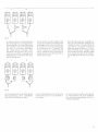
kefnze chnet) geklemmt (siehe F g. 3)
The center conductor is connected to
the "hot" term nal (norma ly red or
marked with "+'), the screening to the
"co d' termina (blac < or malked w th
"- )as Iustrated IFq.3.
former ä son tour un c6b e.
Fa
tes bien
otLAn or a ö qu a ., - d.. tre> r rn ^
br ns de la tresse cie rnasse ne reste ä
l6cart : i pourrait provoquer un court'
circuit D6nuder ensuite le corducteur
nt6rieur sur une longueur de 5 mm. Le
conducteur int6rieur do t ötre raccord6
ä Ia borne (chaude) (en gdn6ra rouge ou
rep-6ree par un (+)) et la tresse de masse
ä la borne {froide) (noire ou rep6r6e par
un r r) (volr fig. 3).
Fig.3
Hat lhr Vo lverstärkerDlN Lautsprecher
Anschlüsse, wird pro Kanal e n entspre
cherder Stecker verwendet - Stecker
rn t Schraubklenrrner sind rf Fachhan
de erhältich Das abgesch rmte Kabe
wird ablso iert w e oben beschr eben.
u ng w rd an den rechteckl
gen, der lfnen eiter an den runden St ft
des D N Lautsprecher Steckers ange
schlossen (s ehe Fig 4)
D e Abschirm
lf your integrated ampl fler is equ pped
wth DN
speaker termnals a corre
spord ng connector is used for each
channe. Connectors with screw type
na ls are ava la ble from Vo! r dea ler
Str p the screened cable as descr bed
above The screen ng s connected to
the rectangular, the center conductor to
the round p n of the D N speaker con
nector (refer to Fig 4)
term
,-
Gj:
\-!
Slvotre amp ificateur int6gre est 6qu p6
de pr ses DIN pour haut-parleurs, i faudra util ser un connecteur correspon
dant pour chaque cana . De tels connec
..ur.,i ab a. ,on| d <,ponib a ä-prÄ
des revendeurs spec al s6es. Le cäb e
sol6 doit etre d6nud6 comme nd qu6
p us haut. La tresse de masse doit 6tre
raccord6e ä a broche rectangu aire du
connecteur D N pour haut-par eurs tand s que 1e signa do t parvenir ä la broche
ronde (voir f ig. 4).
Fig 4
e fo genden Punkte müssen unbe
ingt beachtet werden:
Es gibt Vo lverstarker (v.a. älterer
Bauart), die nicht gegen Kurzschluss
D
d
am Ausgang geschutzt sind.
Kurz
schlüsse zw schen dem Absch rmgeflecht und dem nnen e ter des abge
sch rmten Käbels sind desha b unbe
dingt zu
- Ber
ve rrne den.
versch
edenen
Vol verstärkern
durfen d e Masseansch üsse
des
n
ken und des rechten Kanals nicht ver
bunden werden. Wenn in d esem Fa I
de
Verdrahtungs Variante 2 (sehe
3.2) gewäh t wird. mussen dre Ab
schirmungen von beiden Ansch uss
kabeln uber le e ren W derstand vol.l
100 Ohm an d e (kalten) bzw. r r An
sch üsse des Verstärkers geführt werden (siehe Fig 5)
t
s essenl
a to observe the fo low
ng
po ints:
-
There are integrated amp if ers (part
cu ar y o der models) that are not pro
tected agä nst short c [cuits on th-a
outpuls Short cjrcuits between the
screen ng braid and the center con
ductor must, therefore, be avoided.
On certain types of integrated ampllf i
ers, the ground term nals of the lefthand and the right hand channel may
1.lot be interconnected. lf n this case
the cab ing vers on 2 (see 3 2) s used.
each screen of the two connect ng
cables must be connected to the
"cold" (" ') termjnals via a 100 ohm
reslstor (see
i est impdrat f de veil er aux po nts sui
VANTS:
fig
5)
-
Certains amp if cateurs int6gr6s (e.a
de construction ancleIne) ne sont pas
prot6g6s contre les court-circuits
leurs
sorties
6vter qu'i
ä
faut donc abso ument
se produise un court cir
cu t entre
-
a tresse de rnasse et e con
ducteLrr central du cäble b ind6.
D vers ampl flcateursint6gr6snesup-
portent pas que es prises de masse
des canaux dro t et gauche so ent re
i6es. Sivous optez dans ecaspr6ent
pour la varante de cäblage 2 (volr
3.2), les tresses de masse des deux
cäbles de ia sof do vent0tre chacune
re i6es par une resislance de 100 Ohrn
aux po nts <froidsr, resp. (-) de 'am
pl ficateur (voir f g. 5).
Fig.5
-
ln seltenen Fä len sind die Endstufen
des Vollverstärkers in Brückenschaltung ausgeführt. ln diesen Fällen wird
der nnenleter des Ansch usskabels
mit dem <*r-Ansch luss verbunden.
Die Abs.h r-'rung benöt gl ei-e^
künstlichen Massepunkt, der pro Ka
nal durch einen Spannungs eiter Ue 2
Widerstände von 100 Ohm/1W. siehe
Fig. 6) erzeugt wird.
n rare cases the output stages of the
ntegrated ampl fier are mplemented
as a bridge circu t. ln th s case the center conductor of the connecting cable
is connected to the "+" terminal. The
screen requires an artificial qround
that is created for each channel by a
voltage divider itwo 100 ohm/T W re-
sistors each. Flg.6).
Dans de plus rares cas, les 6tages finaux de l'ampllficateur int6g16 sont
mont6s en pont.
I
convient alors de
raccorder le conducteur centrai du
, ab e de ia -on au poin. .-, Le bl r '
dage n6cesslte pour chaque canal
une masse arllficielle. 16allsee ä l'aide
d un dlviseur de tens on (2 r6sistanre., oF 100 Ol T 1W crac- . vo r I g.
6).
Fig.6
lm Zwe felsfa le zlehen Sie bitte d e Be
dienungsanleitung lhres Verstärkers
oder hren Fachhändler zu Rate.
In case of doubt p ease consultthe operdtrnq r' sl -ct o'-rS ot your aTprlI pr ol
you r dea e[.
En cas de doute, veuillez vous reporter
au mode d'emploi de votre amplificateuT ou encore vous adresser ä votre re
vendeur specialis6.
lm folgenden wird für Vollverstärker, Receiver, Vorverstärker und
Preceiver generell der Ausdruck
(Verstärker) verwendet.
ln the lollowing instructions, the
term "amplifier" is used regardless
of whether it is an integrated amplifier, receiver, preampli{ier. or prece iv er,
Grundsätzi ch gibt es zwei Mög ichke
ten, den Aktvautsprecher AGORA B
von BEVOX an e nen Verstärker anzu
La denomination (amplificateur)
s'applique d6sormais de Iaqon g6n6ralis6e aux amplificateu rs intdgrds.
recepteurs int6gr6s. pr6amplificateurs et p ream p li-tu ners.
Bas ca ly there are two methods ot con
nectlng the REVOX actlve loudspeaker
AGOBA B to an amp ifier.
On d stinoue deux princ pa es facons de
3.1 Version
3.1
raccorder les enceintes act ves AGORA
B ä un amp if cateur
schllessen.
3.1
Variante
1
1
Variante I
AGOBA B
(RrcHT)
AGORA
{LEFT)
Fta.7
Der linke
8252
Verstärkerausgang w rd
durch ein einadr ges, abgeschirmtes
Verb ndungskabel mit der E ngangsbuchse <lN L) des linken Aktiv autspre
chers verbunden. Der Einga ngswahlschalter [7] der linken Box muss auf
(L) stehen.
Der rechte Kanalw rd analog verkabelt.
Der Eingangswahlscha ter l7l des rech-
ten
Aktiv autsprechers muss auf (R)
stehen.
Wichtig:
The left hand ampliJier oulput s connected by a sing e-conductor, screened
cab e to the nput socket "lN L" of the
left hdno " lrve o rd5ppdko Th^ inpul
se ector [7] of the left-hand box must
be in pos tion "U'.
gauche de famplificaleur es1
raccordee ä 'entrde (lN L) de 'encelnte
d, i\F gauche pa un ^äble o- 'iär.on
bl nd6 d un seu conducteur Le selec
teur d entree l7l de 'enceinte gauche
doit Ctre en posltion (L).
La sortie
right hand channel s wired analo
gously The input se ector [7] of the
right l"nd oo\ must D. in po^i io
"R".
gue. Le s6ecteur dentr6e [7]
lm po rta nt:
lm po rta
The
Die Schalterstel ungen (L+B) und (R+B)
sind für den (Durchschleifbetr eb) (Va-
The sw tch pos t ons "L+8" and "R+8"
riante 2) reserviert. Wenn diese Schal
.r"lel L^qe oei Vprlao" rng g6nd.
Va.ia^tp qpwd\'w. do . ,ind grav e
rende Frequenzgangfehler m Tiefton
bere ch d e Folge l
2). Should the latter switch sett ng be
used n conjunct on with the cab ing ar-
10
B
d.e inta d^d for 'loop^6
- odö'(\ ö . on
rangement'1, serious frequency re
I occur n the bass
sponse errors w
ranqe
I
Le canal
droit
est cäb 6 de fagon
a na
de
lo-
en
ceinte droite doit otre en posit on (R).
nt:
Les positions (L+B) et {R+B) du s6 ec
teur sont r6serv6es pour (op6ration en
boucle) (variante 2). De graves pert!r
bations de a r6ponse en fr6quence peu!F dpoArätt a ddn p ^q 1- q a\p ,i
ces positions sont combin6es avec un
cäblage se on a variante 1l
3.2 Variante 2
((Durchschleifbetrieb))
3.2 Version 2
("looped mode")
3.2 Variante 2
((op6ration en boucle))
AGOBA
AGORA B
{BIGHT)
(L
E
B
FT)
E:n--====E
F
I
s.
Die Tonsignale
rp-
8252
des fken und des rechr-r L , r,r. einadr g-n.
F"r"l \ e de
abgesch rmten KabeLn einem der bei
den Aktiv autsprecher zucteführt; der
linke Verstärkerausgang wird m t der
Eingangsbuchse <lN Lr [2], der rechte
Verstärkerausgang wird mlt der Ein
gangsbuchse rlN Rr l2l des selben {m
Be spie des linken) Akt v autsprechers
verbunden. Der Eingangswah scha ter
l7l d eses Lautsprechers steht auf (L).
D e Ausgangsbuchsen [3] des linken
l \ a .l .p-- hö- wc.dFn n r-\ e' ain
^l gen, abgesch rmten Kabe n mit den
adr
E rgangsbuchsen [2] des rechten Ak
t v autsprechers verbunden. Der Ein
ga ngswahlscha lter f7l dieses Lautspre
ches steht auf (R)
Beirn Durchschleifbetrieb muss darauf
geachtet werden, dass die zwei Stereo
känä e ar ke ner Ste le vertauscht werden
I
The audlo s gnals of the left hand and
the right hand channel are taken with
two s ngle conductor, screened cables
to one of the two act ve oudspeakers.
The left hand amp if er output is con
nected to the input socket "lN f' l2l, the
right- "' d anp
o t.t "lN R"
. outp- 'o lL F npL
[2) a' rh. "dne dlr..
oudspeaker (the
rf
left hand oudspeaker
n ou r exa m ple). The
th s speaker is ln pos
input se ector l7l of
t on " r,. The output
sockets f3l of the left hand act ve loud
speaker are connected with two sing e
du tor. .r^ö öd abe. o11- p.
sockets l2l of the right hand active
oudspeaker The input seector l7l of
l^: oed P'6 " t i-Po-ro "R"
O
Care must be taken n ooped mode that
the two stereo chanrels are not con-
fused at any point
I
Les s gnaux de modu at on des canaux
gauche et droit sont amen6s ä 'une des
deux enceintes actlves par deux cäb es
de ia son bllnd6s ä un seu conducteur.
La sortie gauche de I ampl flcateur est
ord.- d 6 trÖa <lN Lr l2l la o.r"
"
droite
de 'ampllficateur est raccord6e
ä I en
". <lN Rr 21 d- la r"^ 6 l. , arrtl.
active (a gauche dans fotre exemple).
Le s6lecteur d'entree l7l de cette en
^in^o l\öö-l pldra Lr (L) L-sp -F
de sorte l3l de 'enceinte active gauche sont reli6es aux prises d entr6e l2l
de l'ence nte active droite. Le s6lecleur
d entr6e [7] de cette ence nte esl p ac6
sur <Rr
Dans e cas d'une opörat on en boucle,
on vei lera ä ne lama s intervertir es
deux canaux ste 160phonlq
ues
I
3.3 Variante 2
mit {BASS BLEND}-Funktion
Die (BASS B LEN D) Funktion ermögl cht
n vrelen lälen eine erhebl cl e Vermin
g '. on ic
oq-cn1s^ 5rö'ger; .l
schen. die durch akustsche Rückkopderu
plunq oder Rumpelstörungen von P at
tensp elern ve.ursacht werden. Dese
Störgo'äL,.hF tnd tn a ge.neir"n belden Kanälen gle ch, haben jedoch
umgekehrles Vorzelchen. Durch Addi
llon des inken und des rechten Kana s
unterha b von rund 50 Hz können dies-^
Störungen wirkungsvolL unterdrückt
werden. Bei aktlvierter <BASS BLENDT
TJnktion werde' oie t et>T.n To^^ 'r rl
der korrekten Lautstärke vom llnken
und rechten Lautsprecher g elch abge-
strahlt. D e räuml che Abbildung des
.la gl ö p^ . wi d dadLrL h ni,-r - beein
trächtigt, da ln diesem Frequenzbere ch
keinerle Stereoinformation enthaiten
ist. Zum Aktiv eren der <BASS BLENDT
Funktlon werden die Einga ngswahl
schalter beider Aktiv autsprecher auf
<L*Br bzw. {R+B} gestel t.
Wichtig:
rekt funktioniert. muss beiden Aktiv
lautsprechern sowoh das linke als auch
das rechte Eingangssignal zugeführt
werden. Ein Anschluss gemäss Variante 2 ist Bedingung tür einwandfreie Tieftonwiedergabe mit aktivierter (BASS BLEN Dr-Funktion.
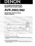
3.4 Kettenbetrieb für meh rere
Aktivlautsprecher
Bei extremem Lautstä rkebeda rf können
mehrere Aktivlautsprecher AGORA
B
werden. Der An
schluss am lVor-)Verstärker erfolgt ge
mäss 3.2. im Beispiel (Fig. B) werden die
Ausgänge des llnken Aktivlautspre
chers mit den Eingängen des nächsten
verbunden. usw Die Stereokanäle werden wie bisher mlt den Eingangswah
schaltern [7] den einzelnen Aktvlaut
sPrechern zugeordnet.
12
ny cases signif cant y reduce ow frequ-
ency noise caused by acoust c feed
ba' . o- , ' ab. runbl- Su h no. ^
signa s are normal y identica on both
hdnnF f,owcvor w th n',erted .igSumm ng of the left hand and the righthand channel below approxin"rate y
50Hz can effectively suppress such
noise. When the "BASS BLEND" func
t on ls active, frequenc es of the low end
of the range a re rad ated ldent ca ly wlth
the correct vo ume by the eft hand and
the right-hand speaker. Th s does not af
fect the spac al proiection of the sound
because no stereo information is carrled
ln this frequencV rancte. The "BASS
BL \D'u u or .d' lvd.ad b\ sa l-g
the input se ectors of both active loudspeakers to "L*B" and "R+8" respect
ve ly
lmportant:
Dam t die <BASS BLENDT Funktion kor
paral elgeschaltel
3.3 Version 2
with "BASS BLEND" function
The "BASS BLEND" function can n rna
The "BASS BLEND" function operates
correct
r
y
on
y lf the left-hand and the
s gna is connected to
ght hand nput
both act ve speakers. Connection according to version 2 is a prerequisite for correct bass reproduction
with active "BASS BLEND" functio n.
3.4 Chained mode for multiple
active lo udspeakers
f exceptonally high volumes are re
qulred, several AGORA B active oud
speakers can be connected in para lel.
The connections on the (pre)ampl fler
are established according to 3.2. ln the
example (Fig. B) the outputs of the left
.pe"\.. d a . o Fct-d to ttr- r-|
"'d
puts of the next speaker e1c The stereo
channels are ass gned to the indiv dual
actve speakers ln the normal manner
wlth the input selector l7l.
3.3 Variante 2
avec fonction <BASS BLENDT
Dans de nombreux cas, la foncllon
<BASS BLENDT permet d att6nuer es
perturbat ons aux basses f16quences
qui sont le plus souvent caus-Äes par es
bruits de r-6acton acoustque et par e
ronflement des tabes de lecture. Ces
perturbations sont trös f rdquemment es
-re.ra pou lF, döu. dndu\ a,P.
prös qu el es sont en opposition de phase. I est a ors possible d att6nuertrös ef
ficacement ces perturbatlons en addi
tionnant es composantes du signal
dont a fr6quence est inferieure ä 50 Hz
Lorsque a fonction (BASS BLEND) est
activee, es sons les plus graves sont re
prodults de la möme fagon par les en
ceintes droite et gauche ävec l'intens t6
sonore correcte. Limage sonore n'est
aucunement inf uencbe par cette correct on car es signaux ä trös basse fr6
quence ne contiennenl aucune informa
tion st616ophonique. La ionctlon rBASS
BLEND) est activ6e orsque le s6lecteur
d entr6e des deux enceintes actives est
pLace sur <L*Br. resp. <R*Br.
Important:
La lonc ion ,BASS B-IND ne'- evi
demment eff cace que si les deux en
celntes actves sont a iment6es par es
deux s gnaux de moduation drot et
gauche. Si on recourt ä Ia fonction
<BASS BLENDT, la reproduction sonore n'est correcte que si les enceintes sont cäbl6es selon la variante 2.
3.4 Raccordement en chaine de
plusieures enceintes actives
Plusieures ence ntes actives AGORA B
peuvent 6tre connect6es en paralldle ä
oü un trös Jort voiume d dcoute est re
quis. Le raccordement au (pre )amp ificateur do t 6tre effectu6 se on 3 2. Dans
notre exemple ({ g. 8), es sorties de 'en
ceinte active gauche sont raccordees
o-\ 6^l ops d^ P .et-llr d, ou\l q-e
suivante, etc. Les canaux st6[-60phoni-
ques sont, somme prec6demment, s6ectionn6s par le s6 ecteur d'entr-6e l7l
de chaque encelnte active.
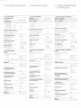
4. SPECIFICATIONS
4. TECHNISCHE DATEN
4. CARACTERISTIOUES
TECHNIOUES
A
A
ÄXIISTISCHE DATEII
iu
N
,:15
5iltl
24
Freqrenzsans
Hz
12 kHr
ll) n 2l
3 dB
Nlirrfaktor Xtot de. Aktvaltspre.reß m
ch
llbedragJngsber""
n I m Abstafd,
be
e n.m Sclre ar!ckpege
be
e n€m
n
A
CARACTERISIIQUES ACOUSTIQUES
Plasede reproduction (DrN i5500): 24Hi 42kFlr
AUDIO SPECIFICATIONS
Bandllidth iD N 45 5!Lr)
Übertragungsbereich
r.1 ex
ll Hi ,lkHr
ifrcrgh.rl
thetr bafd,,r dilr me.surrdatdst.fc€011xr I owre
Freqüency response J dts
LN7
Distorsion HDtot.'1h.r adv-o oLd!p.aker
ge5ar.rte.
nf.allnen
Röponse en fr6qrence ä 3 i8:
3l Hz 21 hllT
Taüx de distorsion Ce ei..nt€a.tve prr. trl,te
pcLrr une pre:r5
max 0 5:r
cr
sOno.e de
SPI
pcLr une p e:s on soncre de
g6dB SPI
i.rir
sn rid pres,i.rre
86IB SPI
lor a sound pres: rre
a
p,agedereprodLrd.i.mesJraä1m€r.hanbre!nurdc
86(iB
051; nax
15
ii
l;l
mrr
max
Sch. dru.kpege
Pression sonore maximale:
Attainable sound pressure levels:
re it !e :o ; llL. n3 r' 19 r.onl
r can rc\,erber.t !n I me 0.:lse.
neasr r€c ai 3 d st;ncs oJ 2 r
w th t,,,,0 .ct re .!aspe:ikeß
lperrt ig s r'rr irne.üs y
Erzielbärer Schalldruckpegel:
o.rogcf aJIW0lr rarnr rf I 10lnr3
n lir.r. Na.lh, rc
z.
Akt
Ia4s i
2m
! aLrtspr..h.r
nBetr€b:
^bsi:nd
secFzetg
n0dBSPL
2x2l0nm
lvlitte ton aLrtsprerh€r O
122 mnr
llochrof
ar
otte
dr;rgc ...caker
tspre.hcr
Tlreeter it ta r
@
lqn
Jn d!n,e d
Masnetic llux density:
i
2
2r l25T i125U{lCl
tte lon a!i5pre.her
Ho.hion a r tsprec her
1,20T 1120N0 Gl
1.90T (1900tG1
lvl
Magnetic
FrilJt nd
n 1m
.h[! lii]r
Arstand,'
AMP,
"PWR A!lP,
l! i=113d8!
12
l'0rrn
g.ben€n Weß
B:s3 I
Klangsteller
Trr-.
.
StLri€n
üdB 2dts
6dB be .laHz
4 !.lra lbare StLrierr
+2lB 0dB, 2.8
Ltrifealed n 0.le.l [i0de.
ha t.f ih. sp.. t ed Na L.e
3eie.1ab ,' step5
Crossover frequencies
(edge steepnessl c' a.. !e
Einschaltschwelle der
Ausschaltverzögerung
der
110
V/22LiV
i2kohn
de op!ral of
'rn0al,rn.e
I
est radute:,rmotadc
adB 2dB
,l dB il l0 kHz
2dB
Contröle de tonalit6 :
'
alrav.s ,l I
A
gJS
ei
veaL.r |onrfir!Lab
4 n veaLrx .(]mmrtab e5
200 Hz
'-1.'lliB./..11
<
2\,'t
FrÖquences de coüpre lpentesl
200 Flr
i',4 /17 dB./oct
aütomälique
:
imV
::0v,220v
+]t';
sirar !N./60
Hz
I2l
enlhors lension automatique
C
Strnd
ii
GETIERALITES
31lis
Abmessunsen rBxHxTr
420r7:5r420 fnr
Ambentartenrper.i!re
rD N
I.UV
22Nl
w
2l
(!
owl
T 1Ä
i:
|]wl
T
r0.c
111.
<
c
C.ss
ll
Weight:
Fl
xDr
kg
2\1")
200w
l5c.F r!5.F]
Conditions de fonctionnernent
r!01!l
Dimensions: lWx
/,
Consommation 6lectrique :
Conditions:
Gewichtl
]liV.,220V 110
:
Nsl
by
20-.
:
(s.Nl
T 1A
:
nrv
Dölai de coupre du chcüit de mise
GEI{ERAL SPICIFICATIOiIS
1]NV
l
dB/!rtl
S€uil de d6clenchement du
circuit de mise en,/hors tension
Power consumption:
lar'C 4!'C
tdB 2dB,ld:
-6dE i 45 Flr
+2 dts iirB 2rB
4lB i l-. kHz
12
l'l1r W
r
en tr4rra e a!ec de,rx .ncc nt0s
eftrO€
Alimentalion 6lectrique
Betriebsbedingungen:
lllllr
6dB at 45Hz
I delay, auto$atic
Power requirements:
Eere,:.helt i"Ster. by,l
iD N
e a:s
4 dB
1mV
teistungsaufnahme:
I Lrfiie ritrt g[e
4V i41,+.-rdBLrt/
äutomätic on,/off circuil:
T 2A (r oP)
I 1A is c,l
!c
D;ns
aclics
raanBLrl,
k0 hnr
i17,'24
C
'e at
P,
tiU9,
l{etzsicherungen:
ll g.! rfgstsnper.tL
4l
:tkHr
Turn-of
1tav
Äl'4
ill75!
Turn-on threshold ol the
'PFE II\4F
ALTGEMEII{E DATEI{
22t)\.i
A[']P,
F
-1,
ImV
12 nV
Ein-,/Arsschaltautomatik:
C
0aB 2aB
I r,h
tt,1/24dP,t..1:
Ein-,/Ausschaltautomatik:
.PRE AIV]P"
"PR
are
Ir.b.4:ee.irbestep:
4cB
2x 612lwb
392!Wb
/
4l kthi'
4Vi:14:aBLr),'
ths rplt rpeCan.. r .ie
il9{l(10 Cr
CARACIERISTIQUES ELECTRIQUES
ll7,-5v la0dBLr.'
ir.t !r: o!c3!9aker5
19|T
:
e.rrs de g.ares
,P\'!R
f 1,,!o
12!rT i12t00 Gl
Entr6es :
Sen: b te po. r un I v.aL re
10!.lB SPL ncsu.ö i 1nr mp6
,
m Dürrh5.h e fbltr eb !of zse Äki! rllspr..1er1 redu
r ert s ch d e E ngrrgs mprd:nz a!f d € lla lte .cs angc
Bass 4 s.ha tbare
Ai!']P
PRI
07l5r.1r4llcBL),
4l l'0h.-
"PRE
B
ELECIRICAI" SPEGIFICATIONS
S.ns tv ty t.r 10t4ts SPL at o s
tance o: 1 n ,' fpL,t riperl;rrce
E ngJngs npedanz
2x1,257 (12500 Gl
haLrllir elr de nrad Lrr]
halt prr eur d a gLrs
l.t_q!\4b
lnputs:
lL10CB SPL
nrt
:
eursdeg..ve5
lraLrt par
hJrt prr e,rr de mad !.r'
l92fWb
3t9.Wb
392pWb
349pWb
122
lntensitä du flux magnätique
ha!lpar
2x 612 | Wb
B
Eingänge
l25 T il2500 Gr
2ilT ll2Uillll)
190T i190l0cr
Flux magnötique
2x 612!Wb
ETEXTRISCHE DATEN
2x 2CCnm
@
m
tllll:
Magnetischer Fluss
lvltte ton a!tsprecher
Hi)chion eütspreaher
11ldB SPL
Haut"parleurs:
lrirLrlpar e,rß de gr:les
haLrt par er r de nrad Lrn O
ha!t par eur d a grs @
m
122n n
@
Magnetische Flussdichte
B
CB SPL
r 2!'l0n
2
lr'l
de d llara€. de[r enc€ ntes act v.s
etanl en iond onr€mr.nt
:
110
Sp€aker conliguralion;
Lautsprecherbestückung
T sft'Jf !Lrtsprer r€r 0
iT taN Ka
: üf
rotorLÖe
ac, d aaoLrtc de
1-n! m3 avant t€m ps d: reverbö':]
r
t rn noyen 0 5. nresuröe ä 2 rn
F
i
HLrn' t! re !t vE
D N 40|40)
de .
:
o
,io
r
.l1kg
Dimensions :
(LrHxPl:
42Ur 7:5 x l2C
nn
5. SERVICE
5. SERVICE
5. SERVICE
Wichtig:
Servicearbeiten dürfen nur vom
Fachmann ausgeführt werden !
Vor dem Abnehmen der Ruckwand
lm po rta nt:
lm po rta nt:
Maintenance work may only be perlormed by trained personnel!
Disconnect power plug before remov-
Les travaux de maintenance ne doi-
Netzsteckverb ndung lösen
D e Betr ebsspanfung der Le stufgsver
ing the back panel
The power ampl
+45 V
D6fa re es connex ons au secteur avant
de d-6poser e panneau arriöre!
La tension d a imentat on des amp f ca
I
stärker beträgt 145 V
Vorsicht beim Beruhren der Leterplat
ten
-ho
hatota
cuit board
L
5.1
Lautsprecherchassis
A._r.b"- oF, dJt pt6rLor .\o .r
ore vo re ä- oer r ^o l\,\ dnd -o' l' l
sind, empfieht es sch, def Aktvlaut
pa hF "rf d- au, l- rpq^'
.le 4 Schrauben
ösen. Steckerverb n
durgen der Ansch ussl tzen ösen.
5.1.1
'*r
rI a \ o
rng
on
with
h'
'
Ho c
hto
n la
uts
p
rec
he
r:
Pluspoi (weisser Punkt)
Minuspo : bla u (blu)
:
braun (brn).
Mitte tonlautsprecher
Pluspol (roter Punkt) : grün (grn),
M nuspo : grau (gry)
Tiefton autsprecher vorne.
P uspol (roter Punkt) : orange (org),
4 screws each d sconrect
p uggab e connect ons
M nuspo
:
schwarz (b
ol the stranded
h eit
Rückwand abschrauben (6 Sen k
schrauber M4. Kreuzschl tz Schrau
bendreher Nr 2: B Senkschrauben fur
Spanplatte, Kreuzschl tz Schrauben
5.1.2 Verstärker-E in
dreher Nr.
When reinsta lng the chassises, the
confect
ofs
rnust be estab ished wlth
the fo owing po ar iy
Tweeter
Posit ve (wh te dot) : brown (brn),
Negat ve = blue {b u)
M drange speaker:
Posit ve (red dot) = green (grn).
Negat ve : grey (gry)
5.1.2
:
parleur de mödlum
pöle positrf (po nt rouge) : vert (grn),
pöle n6gat f : grls (gry)
Haut-pa rleu r de grave avant
HaL"rt
pö
orange (org),
u
-
(red)
pö e negat
and righr o{ swlTcH
BOARD
1AA5 212. 4 on the bottom eft and
r ght of the power transformer), us ng
a recessed head screwdr ver No. 2.
Guide cabe
harness careful y out through the ho
e
n the mountifq p ate.
Beim Wiedere nbau auf korrekte
Farb
zuordnung der L tzen achten siehe Bestückungsplaf m Schernate I (5.3)l
When re nstal ng the amplifier, ensure
that the stranded conductors are con
nected accord ng to the co or scheme:
see component ayout in the diagrams
sect on (5 3)
14
pos t
f
pöe postii
nit
fer unt.
e
(po
nt
roL"rge)
:
orange
pö e ndgat f : vio et (vio)
Haut parie!r de grave supörieur:
cessed head (Phi ips) screws, No 2;
8 countersunk head scr-^ws for
woodchip board, screwdr ver for re
cessed heäd screws, No.1 )
Open 3 cabe runs. detach 4 pin CIS
connector
L ft cable härness out of cab e runs.
detach al the stranded wires
Unfasten 6 screws (2 on upper eft
Remove amp
:
(o rg ),
head screws M4, (screwdr ver for re
1)
Kabe Iuhrungen öffnen, 4 pollgen
CIS Stecker ausstecken
Kabe bündel aus den Kabe führungen
heben. al e L tzen abstecken
6 Schrauben (2 oben inks und rechts
vom Scha ter Panel (SWITCH BOARD
1.485.272).4 unten inks und rechts
vorn Netztransformator) ösen {K reL.rz
sch itz Schraubendreher Nr. 2).
Verstärker E nhet ausbauen. Kabe
b!ndelvorsichtig durch Loch m Mon
lagebLech fädeln.
Amplilier
On ve lera ä respecter a po ar t6 des
td o dF.l Ft O . d- '.rto laqo
Haut parleurs d'a gu
.
Unscrew rear panel,6 countersunk
3
Pour chaq ue haut parleur, d6visser 4 vis
et d6fa re les raccordements aux bornes
pöle posit f {po nt blanc) : brun (brn),
pöle n6gat f : bleu (b u)
Negat ve = vio et (v o)
Woofer, to ll
Posit ve (red dot) : red (red),
Negat ve = black (blk)
k)
Haut-parleu rs
Nous recommandons de placer Ien6itrtö d -t\ö ., p oo .o i- OA po-,oi
d6rnorter p us a s6ment es haut par
eurs qu sont mont6s sur la face avant
de connexion
Posit ve (red dot)
M nuspo = vio ett (v o)
Tieftof autsprecher oben
D Pol (ro. Du, I = ol I Fd)
r
5.1.1
0^"1 ^
mounted on the front acoust c baffle it s
recomrnerded to set the actlve oud
speaker on ts back
wires
Beirn Wledere nbau st die Po ar tät der
Ansch üsse zu beachten:
!
5.1 D6montage
o.ö
Llnfast-^n
liste
les c rcults mprim6s avec p16caution!
Speaker chassises
e-
c ia
.L^d^pu5 dn öa.d-145VSa
I
!
Disassembly
5.1 Ausbau
5.1.1
flers operate
vent Ctre etfectu6s que par un sp6-
f
(po
:
nt rouge) :
noir (b
rouge
k)
5.1.2 Bloc des amplilicateu rs
D6poser e panneau arriöre (6 vis M4,
tournevis cruciforme No. 2; B v s pour
o" ." , "gglo TÄtÄ tO.-. a\ 'l
forn-r e No 'l)
Ouvr r es tro s gu des de cäbles, ef ever le connecteur C S 4 pö es.
- Fa re sortir le fa sceau de cäbles de
ses guides, d6connecter les cäb es.
D6v sser six vis (deux en haut, ä droite
et ä gauche du panneau de commuta
tiof
(SWITCH BOARD 1.085.27
2),
quatre en bas, ä droite et ä gauch-^ du
ro . lorno our a ta ..) to ..no.
cruc f orme No 2).
D6poser e boc des amp fcateurs,
fa re soigneusement passer e fa sceau de cäb es a travers l6v dement
de a p aque de montage
Lors du remontage, on vel lera ä respec
e code des cou eurs de cäbles : se
ter
reporter ä cet effet au plan
d
mp anta
tior dans lä section (sch6ma) (5.3)!
5.1.3 SW|TCH BOARD 1.085.272
Verstärker E nhe t ausbauen (siehe
5.1.3 SWTTCH BOARD 1.085.272
- Remove amp ifier un t according to
5.1.2
5.1.2)
NF Zu
ken
3
eitung (C S Stecker) ausstek
Schrauben (Kreuzschl tz Schrau-
-
bendreher Nr. 'l) ösen (auf der Ver
stärker E nheit ganz oben, von der
Verstä rker
Einheit und
SWLTCH
BOARD 1.085.272 ausbauen (5.1.2
und 51 3)
Netzzule tunqen abstecken (brn, blu).
Anschlüsse des Netztransfo rmato rs
ab öten.
B
Schrauben (Kreuzschlltz'Sch ra u
bendreher Nr 1) am Rand des AUD O
teat.
(p
uggable connecton on AUDO
BOARD 1.085.273)
D6poser le bloc des amplificateurs
-
(voir
5-1_4 AUDTO BOARD 1.Oas.273
-
Remove amp ifier unit and SWITCH
BOARD 1085.272 accord ng to 5.,] 2
and 5 1.3 respectively.
Unplug power ne (brn. blu).
Unsolder the connecting leads of the
power transformer
Unfasten
I
screws (recessed-head
screwdrlver No. 1) at the edge of the
AUD]O BOARD.
When reinstall ng the AUD O BOARD.
ensure th at the conductors are connect
ed accord ng to the co or scheme; see
Ficl
L
5.1 2)
Deconnecter
la
ia son BF (connec
teu r C S).
D6visser trois vis (tournevis crucifor
me No. 1) (pläc6es tout en haut sur le
b oc des a m pl f cateurs et access bles
par la face arr dre).
T rer le panneau vers 'avant (conne
x on enf ch6e sur i'AUDIO BOARD
1
BOARDS lösen.
Beim W edereinbau auf korrekte Farb
zuordnung der Drähte achten - sehe
F g 9l
Unfasten 3 screws (recessed-head
screwdriver No. T) on the top of the
ampl fler unt. accesslble frorn the
Remove board by pul ing it forward
Rückselte her zugä ngl ch).
Pane nach vorne abziehen (Steckver
b ndung auf dem AUDIO BOARD
1.085.273).
5.1.4 AUDrO BOARD 1.O85.273
Detach audio ines (C S connector)
5.1.3 SWTTCH BOARD 1.085.272
.485.27 3)
.
5.1.4 AUDrO BOARD 1.085.273
- D6poser le bloc des ampl f cateurs et
le SW TCH BOARD T.085 212 \voi
5.'1.2 et 5.1 3).
D6connecter
la
ia son secteur (brn,
b u)
Dessouder les raccordements du
transf ormateur secteur.
D6vlsser hu t vis (tournev s cruciforme No T)au bord de 'AUD O BOARD
Lors du remontage, on ve leraärespec
ter le code des couleurs de cäbies rse
reporter ä cet effet ä la
fig
9l
,t ,t ,t l
*@[EI
:
/-L
1 E]1H
CD fr$
l!l1l
B
tl
Htsl
B
rl *[,];
+
F
s. 9
5.1.5 CONNECTOR BOARD 1.085.271
Verstärker E nhe t ausbauen (5.T.2)
NF Zu eltung (C S Stecker) ausstek
ken
Schraube zwischen den CINCI'l
Buchsen ösen (Kreuzsch itz Schraubendreher Nr.
1).
5.1.5 CONNECTOR BOARD 1.085"271
Remove ampl fier unit accord ng to
-
512
Unplug audio ine (C S connector)
Loosen screw between the CINCH
connectors (recessed head screw
dr ver No. l)
5.1.5 CONNECTOR BOARD 1.085.271
D6poser e boc des ampificateurs
(vo r 5
'1.2)
D6connecter a ia son BF (connec
teur CIS).
Dav .\ar lo Vts tl täp .nt F lF- pti^eS
CINCH (tournevis cruciforme No.
T).
15
5.2 Einstellu
ng en
5.2.1 Umschaltung 22Ov l11OV
Die Netzspannungsumscha tung erfo gt
auf dem AUD O BOARD 1.085 273 mit
te s Drahtbrücken Siehe Schemateil
Kaplte 53 Die Netzsicherung ufter
dem Kunststoff Berührungssch utz,
220V: T T A (slow),110V T 2A (s ow)
muss belm Umscha ten der Netzspan
nung oewechselt werden.
5.2.2 Ru hestromeinstellu ng der Leistunqsverstärker
Nach Reparaturarbeiten an den Lei
stungsverstärkern ist elne Einstellung
des Endstufen R u hestroms erforder
lich. Die Elnstel ung erfo gt an der aus
Ve rstärker Einhelt, vorzugs
gebauten
^pi
gen
^ be .Lrzqa. hlor"e'^
Das
R u hestrom -Potent
betreffenden Kana
s
ometer
gä'
-
5.2 Adjustments
5.2 R6g lages
5.2.1 Changeover 22Ov l1lOV
ine voltage can be changed over on
the AUD O BOARD 1085.273 wlrh rhe
a d of so der straps Refer lo the com
ponert ayout (Section 5 3) The power
fuse beow protectve plastc cover,
220v.f 1A (s ow),110V. T 2 A (slow)
must be replaced when the I ne voltage
s cha nqed
5.2.1 Commutation 22OV
The
-
O.u ies cent-c u rre nt adiustment of power ampli{iers
The qu escent current of the power
.d o[ Fl aod
'rdqr. r'l r I O^ r^"d
to the power amp ifiers have been
made. Unfasten the ampllfier unit t is
re onreno"d to -L otl i ,- .l - lh'
5.2.2
I
puts
[ut- Lre qut^ , e U ont Polo io
meter of the corresponding channel
(bass channe RT'16, midrange chan
nel R216. treb e channel R3TO) to the
des
(T eftonkana
RT16. IVlitleltonkanaI R216, Hochton
kana R316) wird an den Anschlag m
-
CFg.nLr '.e'gar)rn 9^b ä'51 /
ma er R u hestrom ).
r-
stop (rninimum
f o..o. Du .O'-r- o ,r-a _i-g
counterc ockw se
quiescent current)
r
rafge'100V) n parallel to one of the
em tter resistors of the power
DC Voltmeter (Messberelch 100V)
paral e zu einem der Emitterwiderstände der Endstuf entransistoren des
betref{efden Kanals anschliessen
(T eftonkana R129. [/]ittelton ka na
R 229. lochtonkana R329).
Aktiv autsprecher ans Netz ansch ies
sen, Wah scha ter fur Eln /Ausschalt
two
stage transistors of the corresponding
channe (bass channel R'129, mid
range chafne R229, treb e channe
I
a
utomatik l8l auf <ONr
Messbere ch des Vo tmeters auf
l0 mV umschalten Ruhestrorn Poten
-
roTprö' d-g a-n in Urr/eigc 'r'
-
16
verstel en, bis am Em tterwiderstand
ein Spannungsabfal von 5 mV
10.5 mV entsteht.
Verstärker-Einheit 30 m n eingescha
tet lassen, Messung erneut durchfüh
ren und, fal s notwendig, Ruhestrom
Potent ometer langsam verdrehen,
bis slch der oben angegebene Spanrungsabfa e nstellt
Netzverbindung lösen, Verstä rker
w eder e nbauen.
5.2.2 R'glage du courant de repos
des amplificateurs de pu issance
Un ajustement du courant de repos est
rendu n6cessa re quand un travail de
malntenance a 6t6 effectu6 sur Les am
pl flcateurs
-
-
Sw
tch
vo
tmeter range
to
'10
169lage
n
n6 (canal grave R129, cana m6dlum
R 229, canal aigu R329).
Raccorder l'ence nte actve au sec-
mV
en/hors serv ce automat que lBl sur
lF.t ptd, Ft ö aonnutd.L.
S owly turn qulescent current potentiometer c ockwlse untl ä voltage
drop of 5 mV aO 5 mV occurs on the
emitter resistor.
Leave amp ifier un t sw tched on for
30 minutes Repeat the measurement
and s owly correct potent ometer set
ting, if necessary, urtl the specfjed
voltage drop ls atta ned.
Dsconnect power AC suppy and
reinstall the amp if er.
de pussance. Ce
effectue aprös depose du bloc des am
p if cateurs, de p16{6rence avec les en
trees en cou rt clrcuit.
- Le potent omötre de reglage du cou
rant de repos du cana concern6 (ca
nal grave Rl16. canal m6dium R216,
' d o, älgu q1l6) do ÄIr^ d1 ön; o
but6e dans le sens inverse des alguil
les d'une montre (courant de repos
min ma ).
Raccorder un vo tmötre CC : (calibre
10OV) en paral öle ävec une des
deux r6slstances d'6metteur des tran
sistors de puissance du cana concers
R329)
,.,o .€ lo tva p6al 6 te lcA(.*p
p V. se ectorforautomat c on/off l8l
"ON" posit on
/ llOV
La commutat on de la tension du sec
teur est r6a is6e pardes ponts cäb,Äs sur
le circuit AUD O BOARD 1.085.273. Se
reporter au p an d rnp antat on dans a
sect on (sch6ma) (5.3). Le fuslble sec
teur (sous a protection anti contact en
plastique, 22AV .I 1A (slow). 110V : T
2 A (slow) doit 6tre chang6 si on com
rnut-o a tenslon du secteur
dP a t5o
rONr
Commuter le callbre du vo tmötre sur
T0mV Faire entement tourner le po
tent omötre de 169lage du courant de
-
repos dans le sens des algu il es d'u ne
montre jusqu ä ce que I on puisse mesurer une chute de tens on de 5mV
lO.5 mV aux bornes de a r6s stance
d 6m etteur
Laiss-.r e bloc des amp f cateurs en
chauffe pendant 30 minutes puis ef
fectuer de nouveau cette rnesure.
R6ajuster si n6cessaire la position du
potentiorndtre de 16g age du couraft
de repos jusqu ä ce que a chute de
tension nomina e solt atteinte.
D6connecter du secteur Remonter le
bloc des arn pl ficateurs
5.3 Schema
5.3 Diagrams
rr-.
5.3 Sch6ma
I -:,-_-rrLrr
I-r -rT-
f'
Tlti
i- i?
.'.
-l
Jt
"t-
L
tnct
2?
/-tf
l
,"''
:fl
I"
rr:-i
Ie
N!
:.Ä
I''
T
TI
+
f)'
,qT.L]]EtrR
at-lLE ?o\
/t7t/ Va? ,/ Sulra, ?.3 /,4uD/D ltz
rbapp 3
lt / 0ta 2 j,/- ,/)
11
;l
T
i.
I
5TI!'DtrR
.c
I
I
AUDTO BOARD 1.085.273
o
o
.'. :
'i
-n
'::.
o
18
o
o
lil:---!l:::1:
19
coNNECTOR BOARD 1.085.271
swlTcH BoaRD 1.o85.272
20
5.4 Spare parts
5.4 Ersatzteile
5.4 Piöces detachees
I ETY I ORDER NUMI]ER I PART NAME
+---------tl 1 I
2 | 1.085.586.00 | roofer
-----l----OZ I I I f.0B5.58B.O0 |"l idranqe I oudspeaker
I
NDEX
+-----------
-----+-----
- --
+
- -- - --
7I.01.O127 I T$,eeter
--- -- +- ----+ ---__-----'---+'---O4 I I I I.085.263.00 | Front cover compl . with f atrric
+ ---------- + -----+ -------------05 I I I I.085.262.O0 | Top cover compl . erith fabric
0llf
-----f-----
I
I
06 I
0? I
I
0B I
I
09 I
f0 I
I
- - --- +- ----
-----+-----+
ff I
-----+-----
c-----------
I f.O8r.27 f.O0 | Connector board
I | 1.085.272.00 I 5!4itch troärd
--------------+-----1 I 1.O85. 21O-04 | Pot/er transformer ll0/?2A
12 I r
or I
r3 I
14 I
f5 I
| 1.085.264.0f I Rear cover
----+ ------- -------I 1.085.270.0O I Amplifier unit compl.
i---------I l.O85.273.OO lAudio board
+
f
+----------
V
V {T r A (slow))
|
51.ol.Oll7 | Power fuse
|
51.01.0120 | Po''{er fuse llO V (T 2 A (slow))
+--------------
+------
22O
1 | r.o23.604.IO I Audio cabler cINCH-CINCHT monor 6,'l
I I f.023.604.20 I Audio cabler CINCH-CINCHt monor l2
{rr
+----------
3
| l.OB5.21 3.OZ I Thermdlly conductive rubber insul.jtor
-----+-----+--------------+-
-----
21