1
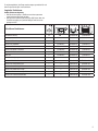
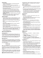
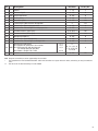
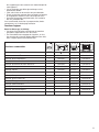
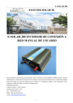
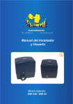
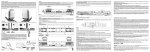
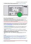
Modell der BR 50
21522
Inhaltsverzeichnis:Seite
Hinweise zur Inbetriebnahme
3
Sicherheitshinweise4
Wichtige Hinweise 4
Multiprotokollbetrieb4
Schaltbare Funktionen 5
CVs und Parameter
6
Ergänzendes Zubehör
26
Wartung und Instandhaltung
27
Ersatzteile31
Indice de contenido:Página
Notas para la puesta en servicio 3
Aviso de seguridad
16
Notas importantes
16
Funcionamiento multiprotocolo
16
Funciones posibles
17
CVs y parámetros
18
Accesorios complementarios
26
El mantenimiento
27
Recambios 31
Table of Contents:Page
Notes about using this model for the first time 3
Safety Notes
7
Important Notes 7
Multi-Protocol Operation 7
Controllable Functions 8
CVs and Parameters
9
Complementary accessories 26
Service and maintenance 27
Spare Parts
31
Indice del contenuto:Pagina
Avvertenza per la messa in esercizio 3
Avvertenze per la sicurezza
19
Avvertenze importanti 19
Esercizio multi-protocollo
19
Funzioni commutabili 20
CV e parametri
21
Accessori complementari
26
Manutenzione ed assistere
27
Pezzi di ricambio 31
Sommaire :Page
Indications relatives à la mise en service 3
Remarques importantes sur la sécurité
10
Information importante 10
Mode multiprotocole 10
Fonctions commutables 11
CVs et paramètres
12
Accessoires complémentaires 26
Entretien et maintien
27
Pièces de rechange
31
Innehållsförteckning:Sidan
Bruksanvisningar för körning 3
Säkerhetsanvisningar22
Viktig information 22
Multiprotokollkörning 22
Kopplingsbara funktioner 23
CV och parametrar
23
Ytterligare tillbehör
26
Underhåll och reparation
27
Reservdelar 31
Inhoudsopgave:Pagina
Opmerking voor de ingebruikname 3
Veiligheidsvoorschriften13
Belangrijke aanwijzing 13
Multiprotocolbedrijf13
Schakelbare functies 14
CV’s en parameter
15
Aanvullende toebehoren
26
Onderhoud en handhaving
27
Onderdelen31
Indholdsfortegnelse:Side
Henvisninger til ibrugtagning 3
Vink om sikkerhed
24
Vigtige bemærkninger 24
Multiprotokoldrift24
Styrbare funktioner 25
CV‘er og parametre
25
Ekstra tilbehør 26
Service og reparation 27
Reservedele 31
2
Radius > 500 mm
Radius > 500 mm
Kurzkupplung zwischen Lok und Tender verstellbar
Close coupling between locomotive and tender is
adjustable
Attelage court réglable entre locomotive et tender
Kortkoppeling tussen loc en tender is verstelbaar
El enganche corto ajustable entre locomotora y ténder
Aggancio corto regolabile tra locomotiva e tender
Kortkopplet mellan lok och tender kan regleras
Kortkobling mellem lok og tender indstillelig
3
Sicherheitshinweise
• Die Lok darf nur mit einem dafür bestimmten Betriebssystem eingesetzt werden.
• Analog max. 15 Volt =, digital max. 22 Volt ~.
• Die Lok darf nur aus als einer Leistungsquelle versorgt
werden.
• Beachten Sie unbedingt die Sicherheitshinweise in der
Bedienungsanleitung zu Ihrem Betriebssystem.
• Für den konventionellen Betrieb der Lok muss das Anschlussgleis entstört werden. Dazu ist das Entstörset
611 655 zu verwenden. Für Digitalbetrieb ist das Entstörset nicht geeignet.
• ACHTUNG! Funktionsbedingte scharfe Kanten und Spitzen.
• Setzen Sie das Modell keiner direkten Sonneneinstrahlung, starken Temperaturschwankungen oder hoher
Luftfeuchtigkeit aus.
Wichtige Hinweise
• Die Bedienungsanleitung und die Verpackung sind
Bestandteile des Produktes und müssen deshalb aufbewahrt sowie bei Weitergabe des Produktes mitgegeben
werden.
• Wartung, Instandhaltung und Reparaturen dürfen nur
durch Erwachsene durchgeführt werden.
• Für Reparaturen oder Ersatzteile wenden Sie sich bitte an
Ihren Trix-Fachhändler.
• Gewährleistung und Garantie gemäß der beiliegenden
Garantieurkunde.
• Entsorgung: www.maerklin.com/en/imprint.html
• Der volle Funktionsumfang ist nur unter Trix Systems,
DCC und unter mfx verfügbar.
• Eingebaute, fahrtrichtungsabhängige Stirnbeleuchtung.
Im Digitalbetrieb schaltbar.
• Befahrbarer Mindestradius 360 mm.
• Rauchsatz nachrüstbar.
einige Einstellungen von Funktionen, welche im AnalogBetrieb wirksam sein sollen, vorgenommen werden.
Hinweise zum Digitalbetrieb
• Die genaue Vorgehensweise zum Einstellen der diversen
Parameter entnehmen Sie bitte der Bedienungsanleitung
Ihrer Mehrzug-Zentrale.
• Die ab Werk eingestellten Werte sind so gewählt, dass
ein bestmöglichstes Fahrverhalten gewährleistet ist.
• Der Betrieb mit gegenpoliger Gleichspannung im
Bremsabschnitt ist mit der werkseitigen Einstellung
nicht möglich. Ist diese Eigenschaft gewünscht, so muss
auf den konventionellen Gleichstrombetrieb verzichtet
werden (CV 29/Bit 2 = 0).
mfx-Protokoll
Adressierung
• Keine Adresse erforderlich, jeder Decoder erhält eine
einmalige und eindeutige Kennung (UID).
• Der Decoder meldet sich an einer Central Station oder
Mobile Station mit seiner UID automatisch an.
Programmierung
• Die Eigenschaften können über die grafische Oberfläche
der Central Station bzw. teilweise auch mit der Mobile
Station programmiert werden.
• Es können alle Configurations Variablen (CV) mehrfach
gelesen und programmiert werden.
• Die Programmierung kann entweder auf dem Haupt- oder
dem Programmiergleis erfolgen.
• Die Defaulteinstellungen (Werkseinstellungen) können
wieder hergestellt werden.
• Funktionsmapping: Funktionen können mit Hilfe der
Central Station 60212 (eingeschränkt) und mit der Central
Station 60213/60214/60215 beliebigen Funktionstasten
zugeordnet werden (siehe Hilfe in der Central Station).
Multiprotokollbetrieb
DCC-Protokoll
Analogbetrieb
Der Decoder kann auch auf analogen Anlagen oder Gleisabschnitten betrieben werden. Der Decoder erkennt die
analoge Gleichspannung (DC) automatisch und passt sich
der analogen Gleisspannung an. Es sind alle Funktionen,
die unter mfx oder DCC für den Analogbetrieb eingestellt
wurden aktiv (siehe Digitalbetrieb).
Adressierung
• Kurze Adresse – Lange Adresse – Traktionsadresse
• Adressbereich:
1 - 127 kurze Adresse, Traktionsadresse
1 - 10239 lange Adresse
• Jede Adresse ist manuell programmierbar.
• Kurze oder lange Adresse wird über die CVs ausgewählt.
• Eine angewandte Traktionsadresse deaktiviert die
Standard-Adresse.
Digitalbetrieb
Der Decoder ist ein Multiprotokolldecoder. Der Decoder
kann unter folgenden Digital-Protokollen eingesetzt werden:
mfx oder DCC.
Das Digital-Protokoll mit den meisten Möglichkeiten ist das
höchstwertige Digital-Protokoll. Die Reihenfolge der DigitalProtokolle ist in der Wertung fallend:
Priorität 1: mfx
Priorität 2: DCC
Priorität 3: DC
Hinweis: Digital-Protokolle können sich gegenseitig beeinflussen. Für einen störungsfreien Betrieb empfehlen wir,
nicht benötigte Digital-Protokolle mit CV 50 zu deaktivieren.
Deaktivieren Sie, sofern dies Ihre Zentrale unterstützt, auch
dort die nicht benötigten Digital-Protokolle.
Werden zwei oder mehrere Digital-Protokolle am Gleis
erkannt, übernimmt der Decoder automatisch das höchst
wertige Digital-Protokoll, z.B. mfx/DCC, somit wird das mfxDigital-Protokoll vom Decoder übernommen.
Hinweis: Beachten Sie, dass nicht alle Funktionen in allen
Digital-Protokollen möglich sind. Unter mfx und DCC können
4
Programmierung
• Die Eigenschaften können über die Configurations Variablen (CV) mehrfach geändert werden.
• Die CV-Nummer und die CV-Werte werden direkt eingegeben.
• Die CVs können mehrfach gelesen und programmiert
werden (Programmierung auf dem Programmiergleis).
• Die CVs können beliebig programmiert werden (Programmierung auf dem Hauptgleis PoM). PoM ist nur bei den in
der CV-Tabelle gekennzeichneten CV möglich. Die Programmierung auf dem Hauptgleis (PoM) muss von Ihrer
Zentrale unterstützt werden (siehe Bedienungsanleitung
ihres Gerätes).
• Die Defaulteinstellungen (Werkseinstellungen) können
wieder hergestellt werden.
• 14 bzw. 28/126 Fahrstufen einstellbar.
• Automatisches Bremsen (CV 27 = Wert 16)
• Alle Funktionen können entsprechend dem Funktionsmapping geschaltet werden.
• Weitere Information, siehe CV-Tabelle DCC-Protokoll.
Es wird empfohlen, die Programmierungen grundsätzlich auf
dem Programmiergleis vorzunehmen.
Logische Funktionen
Anfahr-/Bremsverzögerung
• Die Beschleunigungs- und Bremszeit kann getrennt
voneinander eingestellt werden.
• Die logische Funktionsabschaltung ABV kann über das
Funktionsmapping auf jede beliebige Funktionstaste
gelegt werden.
1
Schaltbare Funktionen
5
STOP
f0 - f3 f4 - f7
f0 f8 f8 f0
mobile station
Stirnbeleuchtung
an
Funktion f0
Funktion f0
Rauchgenerator 1
—
Funktion 1
Funktion f1
Funktion f1
Geräusch: Betriebsgeräusch
—
Funktion 2
Funktion f2
Funktion f2
Geräusch: Lokpfeife
—
Funktion 3
Funktion f3
Funktion f3
Geräusch: Bremsenquietschen aus
—
Funktion 5
Funktion f4
Funktion f4
Geräusch: Kohle schaufeln
—
Funktion 6
Funktion f6
Funktion f6
Geräusch: Glocke
—
Funktion 7
Funktion f7
Funktion f7
ABV aus
—
Funktion 8
Funktion f8
Funktion f8
Geräusch: Luftpumpe
—
—
Funktion f9
Funktion f9
Geräusch: Schüttelrost
—
—
Funktion f10
Funktion f10
Geräusch: Dampf ablassen
—
—
Funktion f11
Funktion f11
Geräusch: Schaffnerpfiff
—
—
Funktion f12
Funktion f12
Geräusch: Bahnhofsansage
—
—
Funktion f13
Funktion f13
Geräusch: Bahnhofsansage Abfahrt
—
—
Funktion f14
Funktion f14
Geräusch: Fahrkartenkontrolle
—
—
Funktion f15
Funktion f15
1 Gehört nicht zum Lieferumfang.
5
CV
1
Wert DCC
Adresse
ab Werk
1 - 127
3
2
PoM Minimalgeschwindigkeit
0 - 255
10
3
PoM Anfahrverzögerung
0 - 255
12
4
PoM Bremsverzögerung
0 - 255
15
5
PoM Maximalgeschwindigkeit
0 - 255
240
131
8
Werkreset/Herstellerkennung
8
13
PoM Funktionen F1 - F8 im Analogbetrieb
0 - 255
0
14
PoM Funktionen F9 - F15 und Licht im Analogbetrieb
0 - 255
1
17
Erweiterte Adresse (oberer Teil)
CV 29, Bit 5 =1
192
18
Erweiterte Adresse (unterer Teil)
CV 29, Bit 5 =1
128
19
Traktionsadresse
21
PoM Funktionen F1 - F8 bei Traktion
22
PoM Funktionen F9 - F15 und Licht bei Traktion
29
Bit 0: Umpolung Fahrtrichtung
Bit 1: Anzahl Fahrstufen 14 oder 28/128*
PoM Bit 2: DCC Betrieb mit Bremsstrecke
(kein Analogbetrieb möglich)
Bit 5: Adressumfang 7 Bit / 14 Bit
63
PoM Lautstärke
PoM * *** 6
Bedeutung
0/1
0/2
0/4
0 / 32
0 - 255
0
0 - 255
0
0 - 255
0
***
0, 1, 2, 3, 4, 5, 6,
7, 32, 34, 35, 36,
37, 38, 39
6
0 - 255
255
Program on the Main; muss vom Steuergerät unterstützt werden
Fahrstufen am Lokdecoder und am Steuergerät müssen übereinstimmen, es sind sonst Fehlfunktionen möglich.
Die Werte der gewünschten Einstellungen sind zu addieren!
Safety Notes
• This locomotive is only to be used with the operating
system it is designed for.
• Analog max. 15 volts DC, digital max. 22 volts AC.
• This locomotive must never be supplied with power from
more than one power pack.
• Please make note of the safety notes in the instructions
for your operating system.
• The feeder track must be equipped to prevent interference with radio and television reception, when the
locomotive is to be run in conventional operation. The
611 655 interference suppression set is to be used for this
purpose. The interference suppression set is not suitable
for digital operation.
• WARNING! Sharp edges and points required for operation.
• Do not expose the model to direct sunlight, extreme
changes in temperature, or high humidity.
Important Notes
• The operating instructions and the packaging are a component part of the product and must therefore be kept as
well as transferred along with the product to others.
• Maintenance, servicing, and repairs may only be done by
adults.
• Please see your authorized Trix dealer for repairs or
spare parts.
• The warranty card included with this product specifies
the warranty conditions.
• Disposing: www.maerklin.com/en/imprint.html
• The full range of functions is only available under Trix
Systems and under DCC.
• Built-in headlights that change over with the direction of
travel. They can be turned on and off in digital operation.
• Minimum radius for operation is 360 mm/14-3/16“.
• A smoke generator can be retrofitted to the locomotive also for analog operation.
Multi-Protocol Operation
Analog Operation
This decoder can also be operated on analog layouts or areas of track that are analog. The decoder recognizes alternating current (DC) and automatically adapts to the analog
track voltage. All functions that were set under mfx or DCC
for analog operation are active (see Digital Operation).
Digital Operation
The decoders are multi-protocol decoders. These decoders
can be used under the following digital protocols: mfx or DCC.
The digital protocol with the most possibilities is the highest
order digital protocol. The sequence of digital protocols in
descending order is:
Priority 1: mfx
Priority 2: DCC
Priority 3: DC
Note: Digital protocols can influence each other. For troublefree operation, we recommend deactivating those digital
protocols not needed by using CV 50. Deactivate unneeded
digital protocols at this CV if your controller supports this
function.
If two or more digital protocols are recognized in the track,
the decoder automatically takes on the highest order digital
protocol, example: mfx/DCC; the decoder takes on the mfx
digital protocol (see previous table).
Note: Please note that not all functions are possible in all
digital protocols. Several settings for functions, which are
supposed to be active in analog operation, can be done
under mfx and DCC.
Notes on digital operation
• The operating instructions for your central unit will give
you exact procedures for setting the different parameters.
• The values set at the factory were selected to guarantee
the best possible running characteristics.
• The setting done at the factory does not permit operation
with opposite polarity DC power in the braking block.
If you want this characteristic, you must do without
conventional DC power operation (CV 29/Bit 2 = 0).
mfx Protocol
Addresses
• No address is required; each decoder is given a onetime, unique identifier (UID).
• The decoder automatically registers itself on a Central
Station or a Mobile Station with its UID.
Programming
• The characteristics can be programmed using the
graphic screen on the Central Station or also partially
with the Mobile Station.
• All of the Configuration Variables (CV) can be read and
programmed repeatedly.
• The programming can be done either on the main track or
the programming track.
• The default settings (factory settings) can be produced
repeatedly.
• Function mapping: Functions can be assigned to any of
the function buttons with the help of the 60212 Central
Station (with limitations) and with the 60213/60214/60215
Central Station (See help section in the Central Station).
DCC Protocol
Addresses
• Short address – long address – multiple unit address
• Address range:
1 - 127 for short address and multiple unit address,
1 - 10239 for long address
• Every address can be programmed manually.
• A short or a long address is selected using the CVs.
• A multiple unit address that is being used deactivates the
standard address.
Programming
• The characteristics can be changed repeatedly using the
Configuration Variables (CV).
• The CV numbers and the CV values are entered directly.
• The CVs can be read and programmed repeatedly. (Programming is done on the programming track.)
• The CVs can be programmed in any order desired. (Programming can be done on the main track PoM). The PoM
can only be done with those designated in the CV table.
Programming on the main track PoM must be supported
by your central controller (Please see the description for
this unit.).
• The default settings (factory settings) can be produced
repeatedly.
• 14/28 or 126 speed levels can be set.
• All of the functions can be controlled according to the
function mapping (see CV description).
• See the CV description for the DCC protocol for additional
7
information.
We recommend that in general programming should be
done on the programming track.
Logic Functions
Acceleration/Braking Delay
• The acceleration and braking time can be set separately
from each other.
• The logic function ABV can be assigned to any function
button by using the function mapping.
1
Controllable Functions
5
STOP
f0 - f3 f4 - f7
f0 f8 f8 f0
mobile station
Headlights
on
Function f0
Function f0
Smoke generator 1
—
Function 1
Function f1
Function f1
Sound effect: Operating sounds
—
Function 2
Function f2
Function f2
Sound effect: Locomotive whistle
—
Function 3
Function f3
Function f3
Sound effect: Squealing brakes off
—
Function 5
Function f4
Function f4
Sound effect: Coal being shoveled
—
Function 6
Function f6
Function f6
Sound effect: Bell
—
Function 7
Function f7
Function f7
ABV off
—
Function 8
Function f8
Function f8
Sound effect: Air pump
—
—
Function f9
Function f9
Sound effect: Rocker grate
—
—
Function f10
Function f10
Sound effect: Blowing off steam
—
—
Function f11
Function f11
Sound effect: Conductor whistle
—
—
Function f12
Function f12
Sound effect: Station announcements
—
—
Function f13
Function f13
Sound effect: Departure announcement
—
—
Function f14
Function f14
Sound effect: Ticket Control
—
—
Function f15
Function f15
1 Not included in delivery scope.
8
CV
Discription
DCC Value
Factory-Set
1
Address
1 - 127
3
2
PoM Minimum Speed
0 - 255
10
3
PoM Acceleration delay
0 - 255
12
4
PoM Braking delay
0 - 255
15
5
PoM Maximum speed
0 - 255
240
8
131
13
8
PoM Functions F1 - F8 in analog operation
Factory Reset / Manufacturer Recognition
0 - 255
0
14
PoM Functions F9 - F15 and lights in analog operation
0 - 255
1
17
Extended address (upper part)
CV 29, Bit 5 =1
192
18
Extended address (lower part)
CV 29, Bit 5 =1
128
19
Multiple Unit Address
21
PoM Functions F1 - F8 on Multiple Unit
22
PoM Functions F9 - F15 and lights on Multiple Unit
29
Bit 0: Reversing direction
Bit 1: Number of speed levels 14 or 28/128*
PoM Bit 2: DCC operation with braking area
(no analog operation possible)
Bit 5: Address length 7 Bit / 14 Bit
63
PoM Volume
0/1
0/2
0/4
0 / 32
0 - 255
0
0 - 255
0
0 - 255
0
***
0, 1, 2, 3, 4, 5, 6,
7, 32, 34, 35, 36,
37, 38, 39
6
0 - 255
255
PoM Program on the Main; must be supported by the controller
* The speed levels on the locomotive decoder and on the controller must agree with each other; otherwise, you may have malfunc-
tions.
*** The values for the desired settings must be added.
9
Remarques importantes sur la sécurité
• La locomotive ne peut être utilisée qu‘avec le système
d‘exploitation indiqué.
• Analogique max. 15 Volt =, digital max. 22 Volt ~.
• La locomotive ne peut pas être alimentée électriquement
par plus d‘une source de courant à la fois.
• Il est impératif de tenir compte des remarques sur la
sécurité décrites dans le mode d‘emploi de votre système
d‘exploitation.
• Pour l’exploitation de la locomotive en mode conventionnel, la voie de raccordement doit être déparasitée. A
cet effet, utiliser le set de déparasitage réf. 611 655. Le set
de déparasitage ne convient pas pour l’exploitation en
mode numérique.
• ATTENTION! Pointes et bords coupants lors du fonctionnement du produit.
• Ne pas exposer le modèle à un ensoleillement direct,
à de fortes variations de température ou à un taux
d‘humidité important.
Information importante
• La notice d‘utilisation et l’emballage font partie intégrante
du produit ; ils doivent donc être conservés et, le cas
échéant, transmis avec le produit.
• Seules des personnes adultes sont habilitées pour
l’entretien, la maintenance et les réparations.
• Pour toute réparation ou remplacement de pièces,
adressez vous à votre détaillant-spécialiste Trix.
• Garantie légale et garantie contractuelle conformément
au certificat de garantie ci-joint.
• Elimination : www.maerklin.com/en/imprint.html
• L’intégralité des fonctions est disponible uniquement en
exploitation Trix Systems, DCC et mfx.
• Feux de signalisation s‘inversant selon le sens de marche; feux commutables en exploitation digital.
• Rayon minimal d’inscription en courbe 360 mm.
• Installation ultérieure d’un générateur de fumée possible
- également pour exploitation analogique.
Mode multiprotocole
Mode analogique
On peut aussi faire fonctionner le décodeur sur des installations ou des sections de voie analogiques. Le décodeur
identifie automatiquement la tension de voie analogique (CC).
Toutes les fonctions qui ont été paramétrée pour le mode
analogique sous mfx ou sous DCC sont actives (voir mode
numérique).
Mode numérique
Les décodeur sont des décodeur multiprotocole. Le
décodeur peut être utilisé avec les protocoles numériques
suivants : mfx, DCC
Le protocole numérique offrant les possibilités les plus
nombreuses est le protocole numérique à bit de poids
fort. La hiérarchisation des protocoles numériques est
descendante :
Priorité 1 : mfx
Priorité 2 : DCC
Priorité 3 : DC
Indication : des protocoles numériques peuvent s’influencer
réciproquement. Pour une exploitation sans perturbations,
nous recommandons de désactiver avec CV 50 des protocoles numériques non nécessaires.
Dans la mesure où votre centrale les supporte, désactivez y
aussi les protocoles numériques non nécessaires.
Lorsque deux ou plusieurs protocoles numériques sont
identifiés au niveau de la voie, le décodeur reprend automatiquement le protocole numérique à bit de poids fort, p. ex.
10
mfx/DCC. Le protocole numérique mfx est donc repris par le
décodeur (voir tableau antérieur).
Indication : remarquez que toutes les fonctions ne peuvent
pas être actionnées dans tous les protocoles numériques.
Sous mfx et sous DCC, il est possible de procéder à
quelques paramétrages de fonctions devant être actives
dans le cadre de l’exploitation analogique.
Remarques relatives au fonctionnement en mode digital
• En ce qui concerne la procédure de réglage des divers
paramètres, veuillez vous référer au mode d‘emploi de
votre centrale de commande multitrain.
• Les valeurs paramétrées d’usine sont choisies de manière à garantir le meilleur comportement de roulement
possible.
• L’exploitation avec courant continu de polarité inverse
dans les sections de freinage n’est pas possible avec
le réglage d’usine. Si cette propriété est désirée, il faut
alors renoncer à l’exploitation conventionnelle en courant continu (CV 29/Bit 2 = 0).
Protocole mfx
Adressage
• Aucune adresse n’est nécessaire, le décodeur reçoit toutefois une identification unique et non équivoque (UID).
• Avec son UID, le décodeur indique automatiquement
à une station centrale ou à une station mobile qu’il est
connecté.
Programmation
• Les caractéristiques peuvent être programmées par
l’intermédiaire de la couche graphique de la station centrale, voire en partie aussi au moyen de la station mobile.
• Toutes les configurations variables (CV) peuvent être lues
et programmées de façon réitérée.
• La programmation peut être réalisée soit sur la voie
principale, soit sur la voie de programmation.
• Les paramétrages par défaut (paramétrages usine)
peuvent être rétablis.
• Mappage des fonctions : les fonctions peuvent être
affectées à de quelconques touches de fonction au
moyen de la station centrale (60212) (restreinte) et avec
la station centrale 60213/60214/60215 (voir Aide au niveau
de la station centrale).
Protocole DCC
Adressage
• Adresse brève – adresse longue – adresse de traction.
• Champ d’adresse : 1 – 127 adresse brève, adresse de traction
1 – 10239 adresse longue
• Chaque adresse est programmable manuellement.
• L’adresse brève ou longue est choisie par l’intermédiaire
des CVs.
• Une adresse de traction utilisée désactive l’adresse
standard.
Programmation
• Les caractéristiques peuvent être modifiées de façon
réitérée par l’intermédiaire des variables de configuration
(CVs).
• Toutes les configurations variables (CV) peuvent être lues
et programmées de façon réitérée.
• La programmation peut être réalisée soit sur la voie
principale, soit sur la voie de programmation.
• Les CVs peuvent être programmées librement (programmation de la voie principale (PoM). La PoM n’est
possible que pour les CVs identifiées dans le tableau des
CVs. La programmation sur la voie principale (PoM) doit
être supportée par votre centrale (voir mode d’emploi de
votre appareil).
• Les paramétrages par défaut (paramétrages usine)
peuvent être rétablis.
• 14/28, voire 126 crans de marche sont paramétrables.
• Toutes les fonctions peuvent être commutées en fonction
du mappage des fonctions (voir le descriptif des CVs).
• Pour toute information complémentaire, voir le tableau
des CVs, protocole DCC.
Il est recommandé, de réaliser la programmation, fondamentalement, sur la voie de programmation.
Fonctions logiques
Retard au démarrage / au freinage
• Les temps d’accélération et de freinage peuvent être
paramétrés séparément les uns des autres.
• Par l’intermédiaire du mappage des fonctions, la mise
hors fonction de la fonction logique ABV peut être affectée à n’importe quelle touche de fonction.
1
Fonctions commutables
5
STOP
Fanal
f0 - f3 f4 - f7
f0 f8 f8 f0
mobile station
Fonction f0
Fonction f0
Générateur de fumée 1
activé
—
Fonction 1
Fonction f1
Fonction f1
Bruitage : Bruit d’exploitation
—
Fonction 2
Fonction f2
Fonction f2
Bruitage : Sifflet locomotive
—
Fonction 3
Fonction f3
Fonction f3
Bruitage : Grincement de freins désactivé
—
Fonction 5
Fonction f4
Fonction f4
Bruitage : Pelletage du charbon
—
Fonction 6
Fonction f6
Fonction f6
Bruitage : Cloche
—
Fonction 7
Fonction f7
Fonction f7
ABV, désactivé
—
Fonction 8
Fonction f8
Fonction f8
Bruitage : Compresseur
—
—
Fonction f9
Fonction f9
Bruitage : Grille à secousses
—
—
Fonction f10
Fonction f10
Bruitage : Échappement de la vapeur
—
—
Fonction f11
Fonction f11
Bruitage : Sifflet Contrôleur
—
—
Fonction f12
Fonction f12
Bruitage : Annonce en gare
—
—
Fonction f13
Fonction f13
Bruitage : Annonce du départ
—
—
Fonction f14
Fonction f14
Bruitage : Contrôle des billets
—
—
Fonction f15
Fonction f15
1 Ne fait pas partie de la fourniture.
11
CV
1
Affectaion
DCC Valeur
1 - 127
3
2
PoM Vitesse minimale
0 - 255
10
3
PoM Temporisation d‘accélération
0 - 255
12
4
PoM Temporisation de freinage
0 - 255
15
5
PoM Vitesse maximale
0 - 255
240
8
131
8
Adresse
Parm. Usine
Réinitialisation d’usine/identification du fabricant
13
PoM Fonctions F1 - F8 en mode analogique
0 - 255
0
14
PoM Fonctions F9 - F15 et éclairage en mode analogique
0 - 255
1
17
Adresse étendue (partie supérieure)
CV 29, Bit 5 =1
192
18
Adresse étendue (partie inférieure)
CV 29, Bit 5 =1
128
19
Adresse traction
21
PoM Fonctions F1 - F8 pour traction
22
PoM Fonctions F9 - F15 et éclairage traction
29
Bit 0: Inv. polarité Sens de marche
Bit 1: Nombre de crans de marche 14 ou 28/128*
PoM Bit 2: Mode DCC avec dist. de freinage (pas possible en mode
analogique)
Bit 5: Capacité d’adresses 7 Bit / 14 Bit
63
PoM Volume
PoM * *** 12
0/1
0/2
0/4
0 / 32
0 - 255
0
0 - 255
0
0 - 255
0
***
0, 1, 2, 3, 4, 5, 6,
7, 32, 34, 35, 36,
37, 38, 39
6
0 - 255
255
Program on the Main; doit être pris en charge par l’appareil de commande
Pour éviter tout dysfonctionnement, les crans de marche sur le décodeur de loco doivent impérativement coïncider avec ceux de l’appareil de commande.
Les valeurs des réglages désirés sont à additioner.
Veiligheidsvoorschriften
• De loc mag alleen met een daarvoor bestemd bedrijfssysteem gebruikt worden.
• Analoog max. 15 Volt =, digitaal max. 22 Volt ~.
• De loc mag niet vanuit meer dan een stroomvoorziening
gelijktijdig gevoed worden.
• Lees ook aandachtig de veiligheidsvoorschriften in de
gebruiksaanwijzing van uw bedrijfssysteem.
• Voor het conventionele bedrijf met de loc dient de
aansluitrail te worden ontstoort. Hiervoor dient men de
ontstoor-set 611 655 te gebruiken. Voor het digitale bedrijf
is deze ontstoor-set niet geschikt.
• OPGEPAST! Functionele scherpe kanten en punten.
• Stel het model niet bloot aan in directe zonnestraling,
sterke temperatuurwisselingen of hoge luchtvochtigheid.
Belangrijke aanwijzing
• De gebruiksaanwijzing en de verpakking zijn een bestanddeel van het product en dienen derhalve bewaard
en meegeleverd te worden bij het doorgeven van het
product.
• Onderhoud, herstellingen en reparaties mogen alleen
door volwassenen uitgevoerd worden.
• Voor reparaties en onderdelen kunt zich tot Uw Trix
handelaar wenden.
• Vrijwaring en garantie overeenkomstig het bijgevoegde
garantiebewijs.
• Afdanken: www.maerklin.com/en/imprint.html
• De volledige toegang tot alle functies is alleen mogelijk
met Trix Systems, DCC of met mfx bedrijf.
• Ingebouwde, rijrichtingsafhankelijke frontverlichting is in
het digitaalsysteem schakelbaar.
• Minimale te berijden radius: 360 mm.
• Rookgenerator nadien in te bouwen.
ingesteld worden.
Aanwijzingen voor digitale besturing
• Het op de juiste wijze instellen van de diverse parameters staat beschreven in de handleiding van uw digitale
Centrale.
• De vanaf de fabriek ingestelde waarden zijn zo ingesteld
dat de rij-eigenschappen optimaal zijn.
• Het bedrijf met tegengepoolde gelijkspanning in de afremsectie is met de fabrieksinstelling niet mogelijk. Indien deze
eigenschap wenselijk is, dan moet worden afgezien van
het conventioneel gelijkstroombedrijf (CV 29/Bit 2 = 0).
Mfx-protocol
Adressering
• Een adres is niet nodig, elke decoder heeft een éénmalig
en éénduidig kenmerk (UID).
• De decoder meldt zich vanzelf aan bij het Central Station
of Mobile Station met zijn UID.
Programmering
• De eigenschappen kunnen m.b.v. het grafische scherm
op het Central Station resp. deels ook met het Mobile
Station geprogrammeerd worden.
• Alle configuratie variabelen (CV) kunnen vaker gelezen
en geprogrammeerd worden.
• De programmering kan zowel op het hoofdspoor als op
het programmeerspoor gebeuren.
• De default-instellingen (fabrieksinstelling) kunnen weer
hersteld worden.
• Functiemapping: functies kunnen met behulp van het
Central Station 60212 (met beperking) en met het Central
Station 60213/60214/60215 aan elke gewenste functietoets
worden toegewezen (zie het helpbestand in het Central
Station.
Multiprotocolbedrijf
DCC-protocol
Analoogbedrijf
De decoder kan ook op analoge modelbanen of spoortrajecten gebruikt worden. De decoder herkent de analoge
gelijkspanning (DC) automatisch en past zich aan de
analoge railspanning aan. Alle functies die onder mfx of DCC
voor het analoge bedrijf zijn ingesteld, worden geactiveerd
(zie digitaalbedrijf).
Adressering
• Kort adres – lang adres – tractie adres
• Adresbereik:
1 – 127 kort adres, tractie adres
1 – 10239 lang adres
• Elk adres is handmatig programmeerbaar.
• Kort of lang adres wordt via de CV gekozen.
• Een toegepast tractieadres deactiveert het standaardadres.
Digitaalbedrijf
De Decoder is een multiprotocoldecoder. De decoder kan
onder de volgende digitale protocollen ingezet worden: mfx,
DCC.
Het digitaalprotocol met de meeste mogelijkheden is het
primaire digitaalprotocol. De volgorde van de digitaalprotocollen is afnemend in mogelijkheden:
Prioriteit 1: mfx
Prioriteit 2: DCC
Prioriteit 3: DC
Opmerking: de digitale protocollen kunnen elkaar beïnvloeden. Voor een storingsvrij bedrijf is het aan te bevelen de
niet gebruikte protocollen met CV 50 te deactiveren. Deactiveer eveneens, voor zover uw centrale dit ondersteunt, ook
de daar niet gebruikte digitale protocollen.
Worden twee of meer digitaal protocollen op de rails
herkend, dan neemt de decoder automatisch het protocol
met de hoogste prioriteit, bijv. mfx/DCC, dan wordt door de
decoder het mfx-digitaalprotocol gebruikt (zie bovenstaand
overzicht).
Opmerking: let er op dat niet alle functies in alle digitaalprotocollen mogelijk zijn. Onder mfx of DCC kunnen enkele
instellingen, welke in analoogbedrijf werkzaam moeten zijn,
Programmering
• De eigenschappen van de decoder kunnen via de configuratie variabelen (CV) vaker gewijzigd worden.
• De CV-nummers en de CV-waarden worden direct ingevoerd.
• De CV’s kunnen vaker gelezen en geprogrammeerd
worden (programmering op het programmeerspoor).
• De CV’s kunnen naar wens geprogrammeerd worden
(programmering op het hoofdspoor PoM). PoM is alleen
bij de in de CV-tabel aangegeven CV’s mogelijk. De
programmering op het hoofdspoor (PoM) moet door uw
centrale ondersteund worden (zie de gebruiksaanwijzing
van uw apparaat).
• De default-instellingen (fabrieksinstelling) kunnen weer
hersteld worden.
• 14/28 resp. 126 rijstappen instelbaar.
• Alle functies kunnen overeenkomstig de functiemapping
geschakeld worden (zie CV-beschrijving).
• Voor verdere informatie, zie de CV-tabel DCC-protocol.
Het is aan te bevelen om het programmeren alleen op het
programmeerspoor uit te voeren.
13
Fysieke functies
Logische functies
Aangezien deze functies uitsluitend via de software uitgevoerd worden, is hier geen fysieke uitgang voor nodig. Daarom
spreekt men hier dan ook van een logische functie.
1
Schakelbare functies
5
STOP
f0 - f3 f4 - f7
f0 f8 f8 f0
mobile station
Frontverlichting
aan
Functie f0
Functie f0
Rookgenerator 1
—
Functie 1
Functie f1
Functie f1
Geluid: bedrijfsgeluiden
—
Functie 2
Functie f2
Functie f2
Geluid: locfluit
—
Functie 3
Functie f3
Functie f3
Geluid: piepende remmen uit
—
Functie 5
Functie f4
Functie f4
Geluid: kolenscheppen
—
Functie 6
Functie f6
Functie f6
Geluid: luidklok
—
Functie 7
Functie f7
Functie f7
ABV, uit
—
Functie 8
Functie f8
Functie f8
Geluid: luchtpomp
—
—
Functie f9
Functie f9
Geluid: schudrooster
—
—
Functie f10
Functie f10
Geluid: stoom afblazen
—
—
Functie f11
Functie f11
Geluid: conducteurfluit
—
—
Functie f12
Functie f12
Geluid: stationsomroep
—
—
Functie f13
Functie f13
Geluid: vertrektekst
—
—
Functie f14
Functie f14
Geluid: kaartcontrole
—
—
Functie f15
Functie f15
1 Maakt geen deel uit van het leveringspakket.
14
CV
1
2
Betekenis
Waarde DCC
Adres
PoM Minimale snelheid
Af fabriek
1 - 127
3
0 - 255
10
3
PoM Optrekvertraging
0 - 255
12
4
PoM Afremvertraging
0 - 255
15
5
PoM Maximumsnelheid
0 - 255
240
8
131
8
Fabrieksinstelling/fabriekherkenning
13
PoM functies F1 - F8 in analoogbedrijf
0 - 255
0
14
PoM functies F9 - F15 en licht in analoogbedrijf
0 - 255
1
17
Uitgebreld adres (bovenste gedeelte)
CV 29, Bit 5 =1
192
18
Uitgebreld adres (onderste gedeelte)
CV 29, Bit 5 =1
128
19
tractieadres
21
PoM functies F1 - F8 in tractie
22
PoM functies F9 - F15 en licht in tractie
29
Bit 0: ompolen rijrichting
Bit 1: aantal rijstappen 14 of 28/128*
PoM
Bit 2: DCC bedrijf met afremtraject (geen analoogbedrijf mogelijk)
Bit 5: adresomvang 7 Bit / 14 Bit
63
PoM Volume
PoM * *** 0/1
0/2
0/4
0 / 32
0 - 255
0
0 - 255
0
0 - 255
0
***
0, 1, 2, 3, 4, 5, 6,
7, 32, 34, 35, 36,
37, 38, 39
6
0 - 255
255
Program on the Main; dient door het besturingsapparaat ondersteunt te worden.
De rijstappen instelling op de decoder en het besturingsapparaat moeten met elkaar overeenkomen anders kunnen er storingen optreden.
De waarde van de gewenste instellingen moeten bij elkaar opgeteld worden.
15
Aviso de seguridad
• La locomotora solamente debe funcionar en el sistema
que le corresponda.
• Analógicas máx. 15 voltios =, digitales máx. 22 voltios ~.
• La locomotora no deberá recibir corriente más que de un
solo punto de abasto a la vez.
• Observe necesariamente los avisos de seguridad indicados en las instrucciones correspondientes a su sistema
de funcionamiento.
• Para el funcionamiento convencional de la locomotora
deben suprimirse las interferencias en la vía de conexión
de la alimentación. Para ello debe emplearse el set
supresor de interferencias 611 655.
• ¡ATENCIÓN! Esquinas y puntas afiladas condicionadas a
la función.
• No exponer el modelo en miniatura a la radiación solar
directa, a oscilaciones fuertes de temperatura o a una
humedad del aire elevada.
Notas importantes
• Las instrucciones de empleo y el embalaje forman parte
íntegra del producto y, por este motivo, deben guardarse
y entregarse junto con el producto en el caso de venderlo
o transmitirlo a otro.
• El mantenimiento, la conservación y las reparaciones
deben ser realizadas siempre por adultos.
• En caso de precisar una reparación o piezas de recambio,
rogamos ponerse en contacto con su distribuidor Trix.
• Responsabilidad y garantía conforme al documento de
garantía que se adjunta.
• Eliminación: www.maerklin.com/en/imprint.html
• La plena funcionalidad de funciones está disponible sólo
en Trix Systems, DCC y en mfx.
• Los faros frontales dependen del sentido de la marcha.
En Digital se pueden encender y apagar.
• Radio mínimo describe 360 mm.
• Kit de humo equipable posteriormente.
Funcionamiento multiprotocolo
Modo analógico
El decoder puede utilizarse también en maquetas de trenes
o tramos de vía analógicos. El decoder detecta la tcontinua
analógica (DC) automáticamente, adaptándose a la tensión
de vía analógica. Están activas todas las funciones que
hayan sido configuradas para el modo analógico en mfx o
DCC (véase Modo digital).
Modo digital
Los decoders son decoders multiprotocolo. El decoder
puede utilizarse con los siguientes protocolos digitales: mfx,
DCC.
El protocolo digital que ofrece el mayor número de posibilidades es el protocolo digital de mayor peso. El orden de
pesos de los protocolos digitales es descendente.:
Prioridad 1: mfx
Prioridad 2: DCC
Prioridad 3: DC
Nota: Los protocolos digitales pueden afectarse mutuamente. Para asegurar un funcionamiento sin anomalías
recomendamos desactivar con la CV 50 los protocolos
digitales no necesarios.
Desactive, en la medida en que su central lo soporte, también en ésta los protocolos digitales no necesarios.
Si se detectan dos o más protocolos digitales en la vía, el
decoder aplica automáticamente el protocolo digital de
mayor peso, p. ej. mfx/DCC, siendo por tanto asumido por el
16
decoder el protocolo digital mfx (véase tabla anterior).
Nota: Tenga presente que no son posibles todas las
funciones en todos los protocolos digitales. En mfx y DCC
pueden configurarse algunos parámetros de funciones que
deben tener efecto en el modo analógico
Informaciones para el funcionamiento digital
• Deberá consultar el procedimiento exacto de configuración de los diversos parámetros en el manual de
instrucciones de la central multitren que desee utilizar.
• Los valores configurados en fábrica se han elegido de
modo que queden garantizadas las mejores características de conducción posibles.
• No es posible el funcionamiento con tensión de corriente
continua de polaridad opuesta en el tramo de frenado en
funcionamiento en modo DCC. Si se desea esta característica, debe renunciarse al funcionamiento convencional
con corriente continua (CV 29/Bit 2 = 0).
Protocolo mfx
Direccionamiento
• No se requiere direccionamiento, recibiendo cada decoder una identificación universalmente única e inequívoca
(UID)
• El decoder se da de alta automáticamente en una Central
Station o en una Mobile Station con su UID:
Programación
• Las características pueden programarse mediante la
interfaz gráfica de la Central Station o bien en parte
también con la Mobile Station.
• Es posible leer y programar múltiples veces todas las
Variables de Configuración (CV).
• La programación puede realizarse bien en la vía principal
o en la vía de programación.
• Es posible restaurar la configuración por defecto (configuración de fábrica).
• Mapeado de funciones: las funciones pueden asignarse
a cualesquiera teclas de función (véase Ayuda en la Central Station) con ayuda de la Central Station 60212 (con
limitaciones) y con la Central Station 60213/60214/60215.
Protocolo DCC
Direccionamiento
• Dirección corta – Dirección larga – Dirección de tracción
• Intervalo de direcciones:
1 – 127 Dirección corta, dirección de tracción
1 – 10239 Dirección larga
• Cada dirección puede programarse manualmente.
• La dirección corta o larga se selecciona mediante las CVs.
• Una dirección de tracción aplicada desactiva la dirección estándar.
Programación
• Las características pueden modificarse múltiples veces
mediante las Variables de Configuración (CV).
• El número de CV y los valores de cada CV se introducen
directamente.
• Las CVs pueden leerse y programarse múltiples veces
(programación en la vía de programación)
• Las CVs pueden programarse libremente. (Programación
en la vía principal PoM). La PoM es posible únicamente
en las CVs identificadas en la tabla de CVs. La programación en la vía principal PoM debe ser soportada por
la central utilizada (véase Descripción de la unidad de
control).
• Las configuraciones por defecto (configuraciones de
fábrica) pueden restaurarse.
• Pueden configurarse 14/28 o bien 126 niveles de marcha.
• Todas las funciones pueden maniobrarse conforme al
mapeado de funciones (véase Descripción de las CVs).
• Para más información, véase Tabla de CVs para protocolo
DCC.
Por norma, se recomienda realizar las programaciones en la
vía de programación.
Funciones lógicas
Retardo de arranque/Retardo de frenado (ABV)
• El tiempo de aceleración y el tiempo de frenado pueden
configurarse por separado.
• La desactivación de la función lógica ABV puede asignarse a cualquier tecla de función mediante el mapeado
de funciones.
1
Funciones posibles
5
STOP
Faros frontales
f0 - f3 f4 - f7
f0 f8 f8 f0
mobile station
Funcióne f0
Funcióne f0
Generador de humo 1
encendido
—
Funcióne 1
Funcióne f1
Funcióne f1
Ruido: ruido de explotación
—
Funcióne 2
Funcióne f2
Funcióne f2
Ruido del silbido de la locomotora
—
Funcióne 3
Funcióne f3
Funcióne f3
Ruido: Desconectar chirrido de los frenos
—
Funcióne 5
Funcióne f4
Funcióne f4
Ruido: Cargar carbón con pala
—
Funcióne 6
Funcióne f6
Funcióne f6
Ruido: Campana
—
Funcióne 7
Funcióne f7
Funcióne f7
ABV, apagado
—
Funcióne 8
Funcióne f8
Funcióne f8
Ruido: Bomba de aire
—
—
Funcióne f9
Funcióne f9
Ruido: Parrilla vibratoria
—
—
Funcióne f10
Funcióne f10
Ruido: Purgar aire comprimido
—
—
Funcióne f11
Funcióne f11
Ruido: Silbato de Revisor
—
—
Funcióne f12
Funcióne f12
Ruido: Locución hablada en estaciones
—
—
Funcióne f13
Funcióne f13
Ruido: Locución de partida
—
—
Funcióne f14
Funcióne f14
Ruido: Verificación de billetes
—
—
Funcióne f15
Funcióne f15
1 No está incluido en el conjunto de piezas suministradas.
17
CV
1
Significado
Valor DCC
1 - 127
3
2
PoM Velocidad mínima
0 - 255
10
3
PoM Arranque progresivo
0 - 255
12
4
PoM Frenado progresivo
0 - 255
15
5
PoM Velocidad máxima
0 - 255
240
8
131
8
Códigos
Preselección
Reset de fábrica/código de fabricante
13
PoM Funciones F1 - F8 en el modo analógico
0 - 255
0
14
PoM Funciones F9 - F15 y luces en el modo analógico
0 - 255
1
17
Dirección ampliada (parte superior)
CV 29, Bit 5 =1
192
18
Dirección ampliada (parte inferior)
CV 29, Bit 5 =1
128
19
Dirección de tracción
0 - 255
0
21
PoM Funciones F1 - F8 en tracción
0 - 255
0
22
PoM Funciones F9 - F15 y luces en tracción
0 - 255
0
29
Bit 0: Cambio de polaridad del sentido de marcha
Bit 1: número de niveles de marcha 14 ó 28/128*
PoM Bit 2: Modo DCC con trayecto de frenado
(no es posible el modo analógico)
Bit 5: Tamaño de direcciones 7 Bits / 14 Bits
***
0, 1, 2, 3, 4, 5, 6,
7, 32, 34, 35, 36,
37, 38, 39
6
63
PoM Volumen
0 - 255
255
0/1
0/2
0/4
0 / 32
PoM Program on the Main; debe ser soportado por la unidad de control
* Los niveles de marcha en el decoder de locomotora y en la unidad de control deben coincidir ya que, de lo contrario, pueden producirse anomalías funcionales.
*** ¡Los valores de los ajustes deseados deben sumarse!
18
Avvertenze per la sicurezza
• Tale locomotiva deve venire impiegata soltanto con un
sistema di esercizio prestabilito a questo scopo.
• Analogico max. 15 Volt =, digitale max. 22 Volt ~.
• La locomotiva non deve venire alimentata nello stesso
tempo con più di una sorgente di potenza.
• Vogliate prestare assolutamente attenzione alle avvertenze di sicurezza nelle istruzioni di impiego per il Vostro
sistema di funzionamento.
• Per il funzionamento tradizionale della locomotiva il
binario di alimentazione deve essere protetto dai disturbi.
A tale scopo si deve impiegare il corredo antidisturbi
611 655. Tale corredo antidisturbi non è adatto per il
funzionamento Digital.
• AVVERTENZA! Per motivi funzionali i bordi e le punte
sono spigolosi.
• Non esponete tale modello ad alcun irraggiamento solare
diretto, a forti escursioni di temperatura oppure a elevata
umidità dell’aria.
Avvertenze importanti
• Le istruzioni di impiego e l’imballaggio costituiscono un
componente sostanziale del prodotto e devono pertanto
venire conservati nonché consegnati insieme in caso di
ulteriore cessione del prodotto.
• Manutenzione, tenuta in efficienza e riparazioni possono
venire eseguite soltanto da parte di adulti.
• Per le riparazioni o le parti di ricambio, contrattare il
rivenditore Trix.
• Prestazioni di garanzia e garanzia in conformità all’accluso certificato di garanzia.
• Smaltimento: www.maerklin.com/en/imprint.html
• La completa dotazione di funzioni è disponibile soltanto
sotto Trix Systems, DCC e sotto mfx.
• IIluminazione di testa incorporata, dipendente dalla direzione di marcia. Commutabile nel funzionamento Digital.
• Raggio minimo percorribile 360 mm.
• Apparato fumogeno equipaggiabile in seguito.
Esercizio multi-protocollo
Esercizio analogico
Tale Decoder può venire fatto funzionare anche su impianti o
sezioni di binario analogiche. Il Decoder riconosce automaticamente la tensione analogica (DC) e si adegua alla tensione
analogica del binario. Vi sono attive tutte le funzioni che erano
state impostate per l’esercizio analogico sotto mfx oppure DCC
(si veda esercizio Digital).
Esercizio Digital
I Decoder sono Decoder multi-protocollo. Il Decoder può
venire impiegato sotto i seguenti protocolli Digital: mfx, DCC.
Il protocollo Digital con il maggior numero di possibilità è il
protocollo digitale di massimo valore. La sequenza dei protocolli Digital, con valori decrescenti, è:
Priorità 1: mfx
Priorità 2: DCC
Priorità 3: DC
Avvertenza: I protocolli Digital possono influenzarsi reciprocamente. Per un esercizio esente da inconvenienti noi
consigliamo di disattivare con la CV 50 i protocolli Digital non
necessari.
Qualora la Vostra centrale li supporti, vogliate disattivare
anche lì i protocolli Digital non necessari.
Qualora sul binario vengano riconosciuti due o più protocolli
Digital, il Decoder accetta automaticamente il protocollo
Digital di valore più elevato. Ad es. mfx/DCC, in tal modo viene
accettato dal Decoder il protocollo Digital mfx (si veda la
precedente tabella).
Avvertenza: Prestate attenzione al fatto che non tutte le
funzioni sono possibili in tutti i protocolli Digital. Sotto mfx e
DCC possono venire eseguite alcune impostazioni di funzioni, le quali saranno efficaci nell’esercizio analogico.
Istruzioni per la funzione digitale
• L’esatto procedimento per l’impostazione dei differenti
parametri siete pregati di ricavarlo dalle istruzioni di
servizio della Vostra centrale per molti treni.
• I valori impostati dalla fabbrica sono scelti in modo tale
che sia assicurato il comportamento di marcia migliore
possibile.
• Un funzionamento con tensione continua di polarità invertita nella sezione di frenatura, in caso di esercizio con
DCC, non è possibile. Se si desidera questa caratteristica,
si deve in tal caso rinunciare al funzionamento tradizionale in corrente continua (CV 29/Bit 2 = 0).
Protocollo mfx
Indirizzamento
• Nessun indirizzo necessario, ciascun Decoder riceve una
sua identificazione irripetibile e univoca (UID).
• Il Decoder si annuncia automaticamente ad una Central
Station oppure Mobile Station con il suo UID.
Programmazione
• Le caratteristiche possono venire programmate tramite la
superficie grafica della Central Station o rispettivamente
in parte anche con la Mobile Station.
• Tutte le Variabili di Configurazione (CV) possono venire
ripetutamente lette e programmate.
• Tale programmazione può avvenire sui binari principali
oppure sul binario di programmazione.
• Le impostazioni di default (impostazioni di fabbrica)
possono venire nuovamente riprodotte.
• Mappatura delle funzioni: con l’ausilio della Central
Station 60212 (limitatamente) e con la Central Station
60213/60214/60215 le funzioni possono venire assegnate
a dei tasti funzione a piacere (si vedano le guide di aiuto
nella Central Station).
Protocollo DCC
Indirizzamento
• Indirizzo breve – Indirizzo lungo – Indirizzo unità di trazione
• Ambito degli indirizzi:
1 – 127 indirizzo breve, indirizzo unità di trazione
1 – 10239 indirizzo lungo.
• Ciascun indirizzo è programmabile manualmente.
• L’indirizzo breve o lungo viene selezionato tramite le CV.
• Un indirizzo di unità di trazione utilizzato disattiva l’indirizzo standard.
Programmazione
• Le caratteristiche possono venire ripetutamente modificate tramite le Variabili di Configurazione (CV).
• Il numero della CV ed i valori della CV vengono introdotti
direttamente.
• Le CV possono venire ripetutamente lette e programmate
(Programmazione sul binario di programmazione).
• Le CV possono venire programmate a piacere (programmazione sul binario principale PoM). La PoM è possibile
soltanto nel caso delle CV contrassegnate nella tabella
delle CV. La programmazione sul binario principale (PoM)
deve venire supportata dalla Vostra centrale (si vedano le
istruzioni di impiego del Vostro apparato).
• Le impostazioni di default (impostazioni di fabbrica)
possono venire nuovamente riprodotte.
• 14/28 o rispettivamente 126 gradazioni di marcia impostabili.
19
• Tutte le funzioni possono venire commutate in modo
rispondente alla mappatura delle funzioni (si veda la
descrizione delle CV).
• Per ulteriori informazioni, si veda la tabella delle CV nel
protocollo DCC.
È consigliabile intraprendere le programmazioni essenzialmente sul binario di programmazione.
Funzioni logiche
Ritardo di avviamento/frenatura (ABV)
• Le durate di accelerazione e di frenatura possono venire
impostate indipendentemente una dall’altra.
• La disattivazione della funzione logica ABV tramite la
mappatura delle funzioni può venire collocata su qualsiasi tasto funzione a piacere.
1
Funzioni commutabili
5
STOP
Illuminazione di testa
1
f0 - f3 f4 - f7
f0 f8 f8 f0
Funzion f0
Funzion f0
mobile station
accesa
—
Funzion 1
Funzion f1
Funzion f1
Rumore: rumori di esercizio
—
Funzion 2
Funzion f2
Funzion f2
Rumore: fischio da locomotiva
—
Funzion 3
Funzion f3
Funzion f3
Rumore: stridore dei freni escluso
—
Funzion 5
Funzion f4
Funzion f4
Rumore: spalatura del carbone
—
Funzion 6
Funzion f6
Funzion f6
Rumore: campana
—
Funzion 7
Funzion f7
Funzion f7
ABV, spento
—
Funzion 8
Funzion f8
Funzion f8
Rumore: compressore dell’aria
—
—
Funzion f9
Funzion f9
Rumore: griglia a scuotimento
—
—
Funzion f10
Funzion f10
Rumore: scarico del vapore
—
—
Funzion f11
Funzion f11
Rumore: fischio di capotreno
—
—
Funzion f12
Funzion f12
Rumore: annuncio di stazione
—
—
Funzion f13
Funzion f13
Rumore: annuncio di partenza
—
—
Funzion f14
Funzion f14
Rumore: controllo biglietti
—
—
Funzion f15
Funzion f15
Apparato fumogeno
1 Non incl. nella fornitura.
20
CV
Significato
Valore DCC
Di fabbrica
1
Indirizzo
1 - 127
3
2
PoM Velocità minima
0 - 255
10
3
PoM Ritardo di avviamento
0 - 255
12
4
PoM Ritardo di frenatura
0 - 255
15
5
PoM Velocità massima
0 - 255
240
8
131
8
Ripristino di fabbrica/Identificazione di produzione
13
PoM Funzioni F1 - F8 in esercizio analogico
0 - 255
0
14
PoM Funzioni F9 - F15 e luci in esercizio analogico
0 - 255
1
17
Indirizzo ampliato (parte superiore)
CV 29, Bit 5 =1
192
18
Indirizzo ampliato (parte inferiore)
CV 29, Bit 5 =1
128
19
Indirizzo di trazione
21
PoM Funzioni F1 - F8 durante trazione
22
PoM Funzioni F9 - F15 e luci durante trazione
29
Bit 0: Scambio poli senso di marcia
Bit 1: numero gradazioni di marcia 14 o 28/128*
PoM Bit 2: Esercizio DCC con tratta di frenata
(nessun esercizio analogico possibile)
Bit 5: Ampiezza indirizzo 7 Bit / 14 Bit
63
PoM Volume
0/1
0/2
0/4
0 / 32
0 - 255
0
0 - 255
0
0 - 255
0
***
0, 1, 2, 3, 4, 5, 6,
7, 32, 34, 35, 36,
37, 38, 39
6
0 - 255
255
PoM Programmazione in linea; deve essere supportata dall’apparato di comando
* Le gradazioni di marcia sul Decoder della locomotiva e sul regolatore di marcia si devono corrispondere, altrimenti sono possibili funzionamenti erronei.
*** I valori delle impostazioni desiderate si devono sommare!
21
Säkerhetsanvisningar
•
•
•
•
Loket får endast köras med därtill avsett driftsystem.
Analog max. 15 Volt =, digital max. 22 Volt ~.
Loket får inte samtidigt försörjas av mer än en kraftkälla.
Beakta alltid säkerhetsanvisningarna i bruksanvisningen
som hör till respektive driftsystemet.
• När den motorförsedda lokdelen ska köras med konventionell drift måste anlutningsskenan vara avstörd.
Till detta använder man anslutningsgarnityr 611 655 med
avstörning och överbelastningsskydd. Avstörningsskyddet får inte användas vid digital körning.
• VARNING! Funktionsbetingade vassa kanter och spetsar.
• Modellen får inte utsättas för direkt solljus, häftiga temperaturväxlingar eller hög luftfuktighet.
Viktig information
• Bruksanvisningen och förpackningen är en del av
produkten och måste därför sparas och alltid medfölja
produkten.
• Underhåll, service och reparationer får endast utföras av
vuxna personer.
• Kontakta din Trix-handlare för reparationer eller reservdelar.
• Garantivillkor framgår av bifogade garantibevis.
• Hantering som avfall: www.maerklin.com/en/imprint.html
• Fullständigt funktionsomfång erhålls endast vid användning av Trix Systems, DCC eller mfx.
• Körriktningsberoende frontbelysning.
Kan kopplas in vid digital drift.
• Kan köras på en minsta radie av 360 mm.
• Röksats kan monteras i efterhand.
Multiprotokollkörning
Analog körning
Dekodern kan även användas vid körning på analoga anläggningar och spåravsnitt. Dekodern känner automatiskt igen
och godtar analog körström, både växelström och likström
(AC/DC). Alla mfx eller DCC funktioner inställda för analog
drift är aktiverade. (v.g. se: Digital körning).
Digital körning
Decoder är en multiprotokolldekoder. Dekodern kan användas tillsammans med följande digital-protokoll: mfx, Dcc,.
Digital-protokollet med flest funktioner är högst prioriterat.
Digital-protokollen inordnas i fallande ordning som följer:
Prioritet 1: mfx
Prioritet 2: DCC
Prioritet 3: fx (MM)
Observera: Digital-protokoll kan påverka varandra. För
störningsfri körning rekommenderas att avaktivera icke
nödvändiga digital-protokoll med CV 50.
Avaktivera också om möjligt de digital-protokoll som ej
används i ert digitala köraggregat.
Om två eller flera digital-protokoll anmäler sej via rälsen på
er anläggning, så föredrar dekodern det högst priotiterade
digital-protokollet, t.ex. mfx/DCC. mfx-digital-protokollet tas
då upp av dekodern. (V.g. se prioriteringstabellen ovan).
Observera: Tänk på att inte alla funktioner kan användas/
aktiveras i alla digital-protokoll. Med mfx och DCC kan vissa
funktionsinställningar göras för att funktionerna ska vara
aktiva vid analog körning.
Anvisningar för digital drift
• Detaljerade anvisningar för att ställa in olika parametrar
finns i bruksanvisningen till Er digitala flertågs-körkontroll.
22
• Fabriksinställda värden har valts för att ge bästa möjliga
köregenskaper.
• Vid DCC-drift kan man inte köra med tvåpolig likspänning
på ett bromsavsnitt. Önskar man ändå genomföra en
sådan körning, så måste man förlita sig på konventionell
likströmsdrift (CV 29/Bit 2 = 0).
mfx-protokoll
Adressering
• Ingen adress behövs, varje dekoder har en helt egen och
entydig adress (UID).
• Dekodern anmäler sej automatiskt till Central Station och
Mobile Station via sin UID.
Programmering
• Egenskaperna kan programmeras via Central Stations
pekskärm och även till vissa delar med Mobile Station.
• Så kan även alla konfigurations-variabler (CV) läsas in
och programmeras.
• Programmeringen kan göras antingen direkt på anläggningens spår eller på programmeringsspåret.
• Default-inställningarna (fabrikens inställningar) kan
återskapas.
• Mappning av funktioner: Funktioner kan med hjälp av
Central Station 60212 (i viss utsträckning) och med
Central Station 60213/60214/60215 kopplas till önskade funktionsknappar (V.g. se mer information i Central Station.)
DCC-protokoll
Adressering
• Korta adresser - långa adresser - multippelkopplingsadresser.
• Adressområde:
1 - 127 korta adresser, multippel kopplings adresser
1 – 10239 långa adresser
• Varje enskild adress kan programmeras manuellt.
• Korta eller långa adresser väljs via CVn.
• En vald multippelkopplingsadress avaktiverar standardadresserna.
Programmering
• Egenskaperna kan ändras flera gånger via konfigurations-variablerna (CV).
• CV-nummer och CV-värden anges direkt.
• Alla CVn kan läsas och programmeras flera gånger
(Programmering görs på programmeringsspåret).
• Alla CVn kan programmeras. (Programmering kan göras
på anläggningens räls PoM). PoM kan endast göras på
CVn som finns upptagna i CV-tabellen. Programmering
på anläggningens räls (PoM) måste understödjas av ert
köraggregat. (V.g. se köraggregatets bruksanvisning).
• Defaultinställningar (fabriksinställningar) kan återskapas.
• 14/28 upp till 126 körsteg kan ställas in.
• Samtliga funktioner kan kopplas in och manövreras enligt
funktions-mappningen. (V.g. se CV-beskrivningen.)
• För ytterligare information: V.g. se CV-tabeller DCC-protokoll.
Vi rekommenderar att endast genomföra programmeringar
på programmerings-spåret.
Logiska funktioner
Accelerations-/bromsfördröjning
• Accelerations- och inbromsningstidernas längd kan
ställas in var för sej.
• Bortkopplingen av logiska funktioner ABV kan via
funktions-mappningen förläggas till vilken som helst av
funktionsknapparna.
1
Kopplingsbara funktioner
5
STOP
f0 - f3 f4 - f7
f0 f8 f8 f0
mobile station
Frontstrålkastare
till
Funktion f0
Funktion f0
Röksats 1
—
Funktion 1
Funktion f1
Funktion f1
Ljud: Trafikljud
—
Funktion 2
Funktion f2
Funktion f2
Ljud: Lokvissla
—
Funktion 3
Funktion f3
Funktion f3
Ljud: Bromsgnissel, från
—
Funktion 5
Funktion f4
Funktion f4
Ljud: Kol skyfflas
—
Funktion 6
Funktion f6
Funktion f6
Ljud: Lokklocka
—
Funktion 7
Funktion f7
Funktion f7
ABV, från
—
Funktion 8
Funktion f8
Funktion f8
Ljud: Luftpump
—
—
Funktion f9
Funktion f9
Ljud: Roster skakas
—
—
Funktion f10
Funktion f10
Ljud: Ånga släpps ut
—
—
Funktion f11
Funktion f11
Ljud: Konduktörvissla
—
—
Funktion f12
Funktion f12
Ljud: Stationsutrop
—
—
Funktion f13
Funktion f13
Ljud: Avgångsmeddelande
—
—
Funktion f14
Funktion f14
Ljud: Hastighetskontroll
—
—
Funktion f15
Funktion f15
1 Ingår inte i leveransen.
CV
1
Betydelse
Värde DCC
Adress
Fabr.inst.
1 - 127
3
2
PoM Minimihastighet
0 - 255
10
3
PoM Accelerationsfördröjning
0 - 255
12
4
PoM Bromsfördröjning
0 - 255
15
5
PoM Maxfart
0 - 255
240
8
131
8
Återställning till fabrikens/tillverkarens ursprungsinställningar
13
PoM Funktion F1 – F8 vid analog drift
0 - 255
0
14
PoM Funktion F9 – F15 samt loklyktor vid analogdrift
0 - 255
1
17
Utvidgad adress (övre del)
CV 29, Bit 5 =1
192
18
Utvidgad adress (undre del)
CV 29, Bit 5 =1
128
19
Multippelkopplingsadresser
0 - 255
0
0 - 255
0
0 - 255
0
***
0, 1, 2, 3, 4, 5, 6,
7, 32, 34, 35, 36,
37, 38, 39
6
0 - 255
255
21
PoM Funktion F1 – F8 vid Multippelkoppling
22
PoM Funktion F9 – F15 samt strålkastare vid Multippelkoppling
29
Bit 0: Polomkastning körriktning
Bit 1: Antal pådragssteg 14 eller 28/128*
PoM Bit 2: DCC Trafik m. bromssträcka (ingen analog körning
möjlig)
Bit 5: Adressomfattning 7 Bit / 14 Bit
63
PoM Ljudstyrka
0/1
0/2
0/4
0 / 32
PoM Program on the Main; fordrar understöd från körkontrollen
* Lok-dekoderns körsteg och körkontrollens körsteg måste stämma överens, annars kan fel betr. funktionerna uppstå.
*** De önskade inställningarnas värden ska adderas/läggas samman!
23
Vink om sikkerhed
• Lokomotivet må kun anvendes med et driftssystem, der er
beregnet dertil.
• Analog max. 15 Volt =, digital max. 22 Volt ~.
• Lokomotivet må ikke forsynes fra mere end én strømkilde
ad gangen.
• Vær under alle omstændigheder opmærksom på de vink
om sikkerhed, som findes i brugsanvisningen for Deres
driftssystem.
• Ved konventionel drift af lokomotivet skal tilslutningssporet støjdæmpes. Dertil skal anvendes støjdæmpningssættet 611 655. Støjdæmpningssættet er ikke egnet til digital
drift.
• ADVARSEL! Skarpe kanter og spidser pga. funktionen.
• Modellen må ikke udsættes for direkte sollys, store
temperaturudsving eller høj luftfugtighed.
Vigtige bemærknnger
• Betjeningsvejledning og emballage hører til produktet og
skal derfor gemmes og medfølge, hvis produktet gives
videre til andre.
• Service, vedligeholdelse og reparationer må kun udføres
af voksne.
• Angående reparationer eller reservedele bedes De
henvende Dem til Deres Trix-forhandler.
• Garanti ifølge vedlagte garantibevis.
• Bortskafning: www.maerklin.com/en/imprint.html
• Det komplette funktionsomfang er kun til rådighed under
Trix Systems, DCC og under mfx.
• Innebygd, kjøreretningsavhengig frontlys.
Kan tændes og slukkes til digitaldrift.
• Farbar mindsteradius 360 mm.
• Røggenerator kan eftermonteres.
Multiprotokoldrift
Analogdrift
Dekoderen kan også benyttes på analoge anlæg eller
sporafsnit. Dekoderen genkender automatisk den analoge
veksel (DC) og tilpasser sig den analoge jævnstrøm. Alle
funktioner, som indstilledes til analogdrift under mfx eller
DCC, er aktive (se digitaldrift).
Digitaldrift
mSD SoundDecodere er multiprotokoldekodere. Dekoderen
kan anvendes ved følgende digital-protokoller: mfx, DCC.
Digital-protokollen med flest muligheder er den højest rangerende digital-protokol. Digital-protokollernes rækkefølge
er med faldende værdi følgende: Prioritet 1: mfx
Prioritet 2: DCC
Prioritet 3: DC
Bemærk: Digital-protokoller kan gensidigt have indflydelse
på hinanden. For at opnå problemfri drift anbefaler vi at
deaktivere ikke anvendte digital-protokoller med CV 50.
Hvis din central giver mulighed for det, så deaktiver også
der de ikke anvendte digital-protokoller.
Genkendes to eller flere digital-protokoller på sporet,
overtager dekoderen automatisk den højest rangerende
digital-protokol, f.eks. mfx/DCC, dermed overtages mfxdigital-protokollen af dekoderen (se foregående tabel).
Henvisninger til digitaldrift
• Den nøjagtige fremgangsmåde til indstilling af de forskellige parametre findes i betjeningsvejledningen til Deres
flertogs-central.
24
• De værdier, der er indstillet fra fabrikken, er valgt således, at der sikres de bedst mulige kørselsforhold.
• Det er ved DCC-drift ikke muligt at anvende drift med
modpolet jævnspænding i bremseafsnittet. Hvis denne
egenskab ønskes, må der gives afkald på den konventionelle jævnstrømsdrift (CV 29/Bit 2 = 0). mfx-protokol
Adressering
• Ingen adresse påkrævet, hver dekoder tildeles en unik og
entydig identitet (UID).
• Dekoderen tilmelder sig automatisk en central station
eller mobile station med sin UID.
Programmering
• Egenskaberne kan programmeres via central stations
grafiske overflade hhv. til dels også med mobile station.
• Alle configuration variable (CV) kan aflæses og programmeres gentagne gange.
• Programmeringen kan enten ske på hoved- eller programmeringssporet.
• Defaultindstillingerne (fabriksindstillinger) kan genindstilles.
• Funktionsmapping: Funktioner kan ved hjælp af central
station 60212 (begrænset) og med central station
60213/60214/60215 tilordnes vilkårlige funktionstaster (Se
hjælp til central station).
DCC-protokol
Adressering
• Kort adresse – lang adresse – traktionsadresse
• Adresseområde:
1 – 127 kort adresse, traktionsadresse
1 – 10239 lang adresse
• Hver adresse kan programmeres manuelt.
• Kort eller lang adresse vælges via CV‘erne.
• En anvendt traktionsadresse deaktiverer standard-adressen.
Programmering
• Egenskaberne kan ændres gentagne gange via configuration variablerne (CV).
• CV-nummeret og CV-værdierne indgives direkte.
• CV’erne kan læses og programmeres gentage gange
(programmering på programmeringssporet).
• CV’erne kan programmeres vilkårligt (programmering på
hovedsporet PoM). PoM er kun mulig ved de i CV-tabellen
markerede CV‘er. Programmeringen på hovedsporet
(PoM) skal supportes af din central (se brugsanvisningen
for dit apparat).
• Defaultindstillingerne (fabriksindstillinger) kan genindstilles.
• 14/28 hhv. 126 kørselstrin kan indstilles.
• Alle funktioner kan styres jævnfør funktionsmapping (se
CV-beskrivelse).
• Yderligere oplysninger, se CV-tabellen DCC-protokol.
Det anbefales principielt at foretage programmeringerne på
programmeringssporet.
Logiske funktioner
Opstart-/bremseforsinkelse
• Accelerations- og bremsetiden kan indstilles særskilt.
• Den logiske funktionsafbrydelse ABV kan lægges på hver
vilkårlig funktionstaste via funktionsmapping.
1
Styrbare funktioner
5
STOP
f0 - f3 f4 - f7
f0 f8 f8 f0
mobile station
Frontbelysning
tændt
Funktion f0
Funktion f0
Røggenerator 1
—
Funktion 1
Funktion f1
Funktion f1
Lyd: Driftslyd
—
Funktion 2
Funktion f2
Funktion f2
Lyd: Lokomotivfløjte
—
Funktion 3
Funktion f3
Funktion f3
Lyd: Pibende bremser fra
—
Funktion 5
Funktion f4
Funktion f4
Lyd: Skovling af kul
—
Funktion 6
Funktion f6
Funktion f6
Lyd: Klokke
—
Funktion 7
Funktion f7
Funktion f7
ABV, fra
—
Funktion 8
Funktion f8
Funktion f8
Lyd: Luftpumpe
—
—
Funktion f9
Funktion f9
Lyd: Rysterist
—
—
Funktion f10
Funktion f10
Lyd: Dampudledning
—
—
Funktion f11
Funktion f11
Lyd: Billetkontrollørfløjt
—
—
Funktion f12
Funktion f12
Lyd: Banegårdsmeddelelse
—
—
Funktion f13
Funktion f13
Lyd: Afgangsmeddelelse
—
—
Funktion f14
Funktion f14
Lyd: Billetkontrol
—
—
Funktion f15
Funktion f15
1 Medleveres ikke.
Betydning
CV
1
Værdi DCC
Adresse
Fra fabrikken
1 - 127
3
2
PoM Mindstehastighed
0 - 255
10
3
PoM Kørselsforsinkelse
0 - 255
12
4
PoM Bremseforsinkelse
0 - 255
15
5
PoM Maksimalhastighed
0 - 255
240
8
131
8
Fabriksnulstilling/Producentmærke
13
PoM Funktionerne F1 - F8 i analogdrift
0 - 255
0
14
PoM Funktionerne F9 - F15 og lys i analogdrift
0 - 255
1
17
Udvidet adresse (Øverste del)
CV 29, Bit 5 =1
192
18
Udvidet adresse (Nederste del)
CV 29, Bit 5 =1
128
19
Traktionsadresse
0 - 255
0
21
PoM Funktionerne F1 - F8 ved traktion
0 - 255
0
22
PoM Funktionerne F9 - F15 og lys ved traktion
0 - 255
0
29
PoM
***
0, 1, 2, 3, 4, 5, 6,
7, 32, 34, 35, 36,
37, 38, 39
6
63
PoM Lydstyrke
0 - 255
255
Bit 0: Omstyring køreretning
Bit 1: Antal stillinger 14 eller 28/128*
Bit 2: DCC-drift med bremselængde (analogdrift ikke mulig)
Bit 5: Adresselængde 7 Bit / 14 Bit
0/1
0/2
0/4
0 / 32
PoM Program on the Main; skal være understøttet af styreenheden
* Indstillingerne på lokomotivets dekoder og på styreapparatet skal stemme overens, da fejlfunktion ellers er mulig.
*** Værdierne for de ønskede indstillinger skal lægges sammen!
25
Causes d‘erreurs potentielles avec le générateur fumigène
• Le générateur fumigène ne peut pas être rempli de
liquide fumigène au-delà de la moitié du tube.
• Aucune bulle d‘air ne peut se trouver dans le générateur
fumigène.
• Le câble de raccordement raccordé à la face inférieure
du fumigène doit posséder un contact sûr avec le ressort
de connexion dans le châssis de la locomotive.
7226
Potentiële storingsoorzaken bij rookgeneratoren
• De rookgenerator mag maximaal half met rookolie gevuld
worden.
• In de rookgenerator mag zich geen luchtbel bevinden.
• De aansluitdraad aan de onderzijde van de rookgenerator
moet een betrouwbaar contact maken met de contactveer in het locomotief onderstel.
Instrucciones importantes para el buen uso del fumígeno
• Llenar el cartucho solamente hasta la mitad con líquido
fumígeno.
• Prestar atención que no se forme una burbuja de aire en
el cartucho.
• El hilo tomacorriente de la base debe tener un buen
contacto con el resorte que está en el bastidor de la
locomotora.
Potenziali origini di guasti nel caso dell’apparato fumogeno
• L’apparato fumogeno come massimo deve essere riempito solamente a metà di olio vaporizzabile.
• Nell’apparato fumogeno non deve trovarsi alcuna bolla
d’aria.
• Il conduttore di alimentazione sulla faccia inferiore
dell’apparato fumogeno deve possedere un sicuro
contatto verso la molla di connessione nel telaio della
locomotiva.
Potentiella felkällor på rökgeneratorn
• Rökgeneratorn får maximalt fyllas till hälften med rökvätska
• I rökgeneratorn får inte finnas någon luftblåsa
• Anslutningstråden på rökgeneratorns undersida måste ha
en säker kontakt med anslutningsfjädern i lokets chassi.
Potentielle Fehlerquellen beim Rauchgenerator
• Der Rauchgenerator darf nur maximal halb mit Rauchöl
gefüllt sein.
• Im Rauchgenerator darf sich keine Luftblase befinden.
• Der Anschlussdraht an der Unterseite des Rauchgenerators muss sicheren Kontakt zur Anschlussfeder im
Lokomotiv-Fahrgestell besitzen.
Potential Problems with the Smoke Generator
• The smoke generator cannot be filled any more than
halfway with smoke fluid.
• There should not be any air bubbles in the smoke generator.
• The connecting wire on the underside of the smoke generator must have a clean contact with the connection field
in the locomotive’s frame.
26
Potentielle fejlkilder ved røggeneratoren
• Røggeneratoren må maksimalt være halvt fyldt med
røgolie.
• Der må ikke være nogen luftbobler i røggeneratoren.
• Der skal være en god og sikker kontakt mellem
tilslutningstråden på undersiden af røggeneratoren og
tilslutningsfjederen i lokomotivets understel.
2,5 mm
27
40h
28
29
30
10
16
2
30
16
12
1
2
12
30
12
4
24
33
31
23
4
5
31
27
17
25
8
31
6
34
8
8
9
9
8
31
26
21
29
15
7
31
31
21
4
4
29
5
24
33
22
6
Details der Darstellung
können von dem Modell
abweichen.
31
18
18
6
17
3
19
19
28
32
63
9
9
13
20
13
14
20
14
Details der Darstellung können von dem Modell abweichen.
1
2
3
4
5
6
7
8
9
10
11
12
13
14
15
16
17
18
19
20
15
21
22
23
24
25
26
27
28
29
30
31
32
33
34
Motor
Schraube
Decoder
Schraube
Schraube
Schraube
Vorlaufgestell
Haftreifen
Deichsel, Zugstange
Fenster
Laternen
Laternen
Schraube
Schleifer
Kupplung
Windleitbleche
Glühlampe hell
Leitern, Lichtkörper
Lautsprecher
Drehgestellblende
Bremsattrappe
Gestänge, links
Gestänge, rechts Zylinder
Federplatte
Puffer rund Schraube
Haltebügel
Schraube
Graphitbürste
Kuppelstangen
Puffer
Mutter
Isolierplatte
Kolbenstangenschutzrohr
Heizer
Lokführer
E165 841
E784 980
194 117
E499 840
E499 850
E786 750
E195 536
7 153
E195 537
E174 686
—
E195 538
E750 230
E200 211
E701 630
E195 546
E610 080
E195 545
E180 731
E210 127
E464 780
E210 124
E210 116
E180 624
E343 590
E761 720
E750 200
E222 005
E753 100
E601 460
E183 407
E761 710
E499 830
E253 600
E213 450
E602 290
E602 280
Hinweis: Einige Teile werden nur ohne oder mit anderer
Farbgebung angeboten.
Teile, die hier nicht aufgeführt sind, können nur im Rahmen
einer Reparatur im Märklin-Reparatur-Service repariert
werden.
Due to different legal requirements regarding electro-magnetic compatibility, this item
may be used in the USA only after separate certification for FCC compliance and an
adjustment if necessary.
Use in the USA without this certification is not permitted and absolves us of any liability. If you should want such certification to be done, please contact us – also due to the
additional costs incurred for this.
Gebr. Märklin & Cie. GmbH
Stuttgarter Straße 55 - 57
73033 Göppingen
Germany
www.trix.de
32
www.maerklin.com/en/imprint.html
194177/0413/Ha1Ef
Änderungen vorbehalten
© Gebr. Märklin & Cie. GmbH