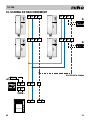
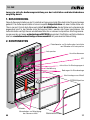
1
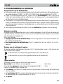
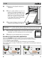
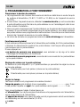
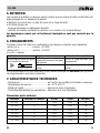
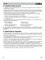
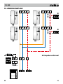
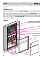
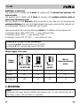
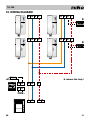
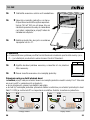
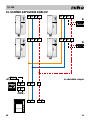
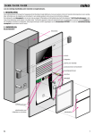
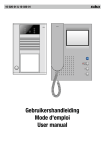
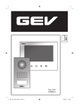
10-15X
Lees de volledige handleiding vóór installatie en ingebruikname.
1. BESCHRIJVING
Deze audiobuitenpost uit het gamma Toegangscontrole Standaard is bestemd voor deurtelefonie.
De buitenpost is een compacte opbouwpost met 16mm opbouwhoogte. Afhankelijk van het
bestelde type heeft de buitenpost 1 tot 8 beldrukknoppen, die zich in één kolom onder
elkaar bevinden. In de tabel onder ‘Technische gegevens’ staan alle types beschreven. De
buitenpost is voorzien van een instelbare microfoon en luidspreker. Alle programmeringen
worden opgeslagen op een uitneembaar EEPROM. Er is ook een vandaalbestendige
naamplaat die permanent verlicht wordt.
2. ONDERDELEN
potentiometers om de geluidssterkte van
de microfoon en luidspreker te wijzigen
luidspreker
aansluitklemmen
LED
aansluiting service-apparaat
kabeldoorvoer
gaten voor wandmontage
metalen afschermkap
EEPROM-geheugen
NL
microfoon
klemveren om de
naamplaat te bevestigen
naamkaartjes
1
10-15X
Bijkomende benodigdheden
De buitenpost wordt 2-draads bekabeld voor systemen met 1 buitenpost en max. 20
binnenposten.
De buitenpost wordt 3-draads bekabeld voor systemen met meerdere buitenposten of
meer dan 20 binnenposten.
Let daarnaast op de diameter van de aders in de kabel want deze bepaalt de maximum
afstand die behaald kan worden tussen de voeding en de buitenpost. Om grotere afstanden
te behalen kunnen paren dubbel worden genomen.
Niko raadt aan om de volgende kabels te gebruiken voor de installatie van de binnenpost:
• Diameter 0,8mm (SVV, JYSTY, TVVF,…): max. afstand 250m
• Diameter 0,6mm (TPVF,…): max. afstand 150m
• Diameter 0,5mm (UTP, FTP, STP,…): max. afstand 100m
Waarvoor dienen de aan te sluiten draden?
• klemmen a & b: communicatiebus (24VDC)
• klem P (& b) : extra voeding (26VDC)
Welke voeding moet u gebruiken?
Voeding
Max # 10-501
/ 10-511(-50)
Max #
10-535-01
Max #
10-512
Max #
buitenposten
parlo
10-801
20
6
5
2
10-802
80
36
7
4
10-801 &
10-805-01
180
90
60
>4
3. MONTEREN
Let op!
Installeer de buitenpost niet onder spanning. Sluit het toestel pas na volledige installatie
aan op de netspanning.
2
NL
10-15X
➥
1Verwijder de vandaalbestendige naamplaat.
➥
2Bevestig de buitenpost aan de muur.
De aangewezen montagehoogte vanaf
de grond voor de luidspreker is 150 tot
160 cm. Om te vermijden dat er water
langs de kabel in het toestel loopt brengt
u best de kabel van onder naar boven in
het toestel!
➥
3Sluit de bekabeling aan volgens het
aansluitschema op pag.7.
1
3
2
Opmerking
• Gebruik in één systeem dezelfde kleurencode voor dezelfde klemmen (a, b, P, ...)
voor alle producten van het gamma Toegangscontrole Standaard.
➥
4U kan de bijgeleverde blanco naamkaartjes invullen en achter
de witte plastic folie van de naamplaat schuiven.
➥
5Plaats de naamplaat terug in de buitenpost.
Een extra deuropener relais koppelen
U kan optioneel een deuropener relais aansluiten op de buitenpost tussen klem R en P.
Dit relais moet in volgende situaties geplaatst worden:
• als er meerdere buitenposten zijn
• als lokaal aan de buitenpost een deuropenercontact voorzien moet zijn
U kan relais 10-835 plaatsen in een inbouwdoosje achter de buitenpost.
ab
PR
ab
Relais
10-835
NL
2-draads
PR
Relais
10-835
3-draads
3
10-15X
4. PROGRAMMEREN en WERKING
Programmeren op de beldrukknop
•Het programmeren van de beldrukknoppen wordt uitvoerig beschreven in de handleiding van
de systeemvoeding (10-801, 10-802 of 10-806) of van het servicetoestel (10-870).
•Indien u het servicetoestel gebruikt, scheur dan het serienummer af dat u terugvindt
achter het naamplaatje onder de witte folie van de buitenpost of in de verpakkingsdoos
en kleef het op uw installatieschema.
•U kan slechts 1 binnenpost op de geheugenplaats van elke beldrukknop programmeren.
Indien u meerdere binnenposten wil programmeren moet u master-slave programmering
op de binnenposten toepassen. Raadpleeg daarvoor de handleiding van het servicetoestel
of de binnenpost.
•Een ongeprogrammeerde beldrukknop zal het lichtrelais schakelen van de voeding.
Algemene werking
Als alles correct is aangesloten en er wordt voeding aangelegd, zal de LED van de buitenpost
oplichten. Bij het afnemen van een hoorn op een binnenpost moet er steeds communicatie
met de buitenpost mogelijk zijn.
Als u drukt op een:
•Ongeprogrammeerde beldrukknop, hoort u hoge beep en wordt het lichtrelais van
de voeding aangetrokken
•Geprogrammeerde beldrukknop, hoort u belgerinkel aan de buiten- en de binnenpost.
Volume aan de buitenpost regelen
Onder de metalen afschermkap bevinden zich 2 potentiometers waar u het volume aan
de buitenpost kan regelen.
potentiometer voor luidspreker (geluidssterkte aan de buitenpost)
potentiometer voor microfoon (geluidssterkte aan de binnenpost)
Tijden instellen
Standaard zijn de volgende tijden geprogrammeerd:
Spreektijd na het starten van een gesprek.................................. Max 2min
Duur dat een oproep van een buitenpost gesignaleerd blijft.......... 2min
Je kan ook andere tijden instellen via
•de voeding. Voor meer informatie over het programmeren via de voeding, zie handleiding
van de voeding.
•het servicetoestel. Voor meer informatie over het programmeren via het servicetoestel,
zie handleiding van het servicetoestel (10-870).
•het relais.
4
NL
10-15X
5. ONDERHOUD
Met onderstaande onderhoudstips wil Niko vermijden dat het oppervlak van je product door
verkeerde behandeling beschadigd wordt.
•Reinig het product met wat zeep en een vochtige doek.
•Gebruik nooit:
-schurende sponzen of schurende reinigingsmiddelen;
-onderhoudsmiddelen die een oplosmiddel of een zuur bevatten of schoonmaakmiddelen
met azijnzuur.
Beschadiging door verkeerde behandeling valt niet onder de garantie.
6. TROUBLESHOOTING
Controleer eerst met een multimeter of volgende spanningen aanwezig zijn:
-tussen b en a: ................... ca. +24 VDC
-tussen b en P: ................... ca. +24 VDC
(b of M = massa)
Fout
oorzaak
negatieve toon bij het drukken op fout in de programmering of
bijhorende binnenpost niet goed
de beldrukknop
geïnstalleerd
installatie in programmeermode
Controle en/of oplossing
programmering wissen en
opnieuw uitvoeren
programmeermode verlaten
Indien de buitenpost vervangen moet worden, kan u de EEPROM van de toestellen uitwisselen. Zo blijft de programmering behouden.
7. TECHNISCHE GEGEVENS
- Afmetingen:............................... afhankelijk van type (zie tabel hieronder)
- Bedrijfstemperatuur:.................. -20°C tot 50°C
- Metalen behuizing:.................... 4mm dik aluminium
- Vandaalbestendige naamplaat:... 4mm dik macrolonglas
Afmetingen buitenpost
NL
referentie
# beldrukknoppen
h (mm)
b (mm)
d (mm)
10-151
1
153
104
16
10-152
2
153
104
16
10-153
3
153
104
16
10-154
4
153
104
16
10-156
6
197
104
16
10-158
8
241
104
16
5
10-15X
8. WETTELIJKE WAARSCHUWINGEN
-De installatie dient te worden uitgevoerd door een bevoegd persoon en met inachtname
van de geldende voorschriften.
-Deze handleiding dient aan de gebruiker te worden overhandigd. Zij moet bij het dossier
van de elektrische installatie worden gevoegd en dient te worden overgedragen aan
eventuele nieuwe eigenaars. Bijkomende exemplaren zijn verkrijgbaar via de Niko-website
of -supportdienst.
-Bij de installatie dient rekening gehouden te worden met (lijst is niet limitatief):
-de geldende wetten, normen en reglementen;
-de stand van de techniek op het ogenblik van de installatie;
-het feit dat een handleiding alleen algemene bepalingen vermeldt en dient gelezen te
worden binnen het kader van elke specifieke installatie;
-de regels van goed vakmanschap.
-Bij twijfel kan u de supportdienst van Niko raadplegen of contact opnemen met een erkend
controleorganisme.
Support België: Support Nederland:
tel. + 32 3 778 90 80
tel. + 31 183 64 06 60
website: http://www.niko.be
website: http://www.niko.nl
e-mail: [email protected] e-mail: [email protected]
In geval van defect kan u uw product terugbezorgen aan een erkende Niko-groothandel
samen met een duidelijke omschrijving van uw klacht (manier van gebruik, vastgestelde
afwijking…).
9. GARANTIEBEPALINGEN
-Garantietermijn: twee jaar vanaf leveringsdatum. Als leveringsdatum geldt de factuurdatum
van aankoop van het goed door de consument. Indien geen factuur voorhanden is, geldt
de productiedatum.
-De consument is verplicht Niko schriftelijk over het gebrek aan overeenstemming te
informeren, uiterlijk binnen de twee maanden na vaststelling.
-In geval van een gebrek aan overeenstemming van het goed heeft de consument recht
op een kosteloze herstelling of vervanging, wat door Niko bepaald wordt.
-Niko is niet verantwoordelijk voor een gebrek of schade als gevolg van een foutieve installatie, oneigenlijk of onachtzaam gebruik of verkeerde bediening of transformatie van het
goed.
-De dwingende bepalingen van de nationale wetgevingen betreffende de verkoop van
consumptiegoederen en de bescherming van de consumenten van de landen waarin
Niko rechtstreeks of via zuster/dochtervennootschappen, filialen, distributeurs, agenten
of vaste vertegenwoordigers verkoopt, hebben voorrang op bovenstaande bepalingen.
6
NL
10-15X
10. Aansluitschema
a b E P
a b E P
�
12V 1A max
a b E P
a b E P
�
12V 1A max
✱ verwijder het lampje !
16 17
a b
P
a b
P R
1 3
230V~
NL
7
10-15X
8
NL
10-15X
Lisez entièrement le mode d’emploi avant toute installation et mise en service.
1. Description
Ce poste extérieur audio de la gamme Contrôle d’accès standard est destiné à la parlophonie.
Le poste extérieur est un poste en saillie compact d’un encombrement de 16 mm. En
fonction du modèle commandé, le poste extérieur possède de 1 à 8 boutons de sonnerie,
disposés les uns en dessous des autres en une colonne. Vous retrouverez la description
de tous les modèles dans le tableau sous ‘Caractéristiques techniques’. Le poste extérieur
est muni d’un microphone et d’un haut-parleur réglables. Toutes les programmations sont
enregistrées dans une EEPROM amovible. Un porte-étiquette résistant au vandalisme et
éclairé en permanence a également été prévu.
2. PIECES
potentiomètres pour modifier le volume
du microphone et du haut-parleur
haut-parleur
bornes de raccordement
LED
connexion appareil de service
passe-câble
trous pour montage mural
capot protecteur en métal
mémoire EEPROM
FR
microphone
ressorts de fixation
du porte-étiquette
étiquettes
9
10-15X
Matériel complémentaire
Le poste extérieur est câblé à 2 fils pour des systèmes comprenant 1 poste extérieur et
max. 20 postes intérieurs.
Le poste extérieur est câblé à 3 fils pour des systèmes comprenant plusieurs postes
extérieurs ou plus de 20 postes intérieurs.
Tenez compte en outre du diamètre des conducteurs dans le câble, celui-ci déterminant la
distance maximale pouvant être couverte entre l’alimentation et le poste extérieur. Pour
couvrir une plus grande distance, les paires peuvent être prises doubles.
Niko conseille l’utilisation des câbles suivants pour l’installation du poste extérieur:
• Diamètre 0,8 mm (SVV, JYSTY, TVVF,…): distance max. 250 m
• Diamètre 0,6 mm (TPVF,…): distance max. 150 m
• Diamètre 0,5 mm (UTP, FTP, STP,…): distance max. 100 m
A quoi servent les fils à raccorder?
• bornes a & b: bus de communication (24V DC)
• borne P (& b) : alimentation supplémentaire (26V DC)
Type d’alimentation à utiliser
Alimentation
# max 10-501
/ 10-511(-50)
# max
10-535-01
# max
10-512
# max
de postes
extérieurs parlo
10-801
20
6
5
2
10-802
80
36
7
4
10-801 &
10-805-01
180
90
60
>4
3. MONTAGE
Attention!
N’installez pas le poste extérieur sous tension. Ne raccordez l’appareil à la tension
réseau qu’après installation complète.
10
FR
10-15X
➥
1Retirez le porte-étiquette résistant au
vandalisme.
➥
➥
2Fixez
le poste extérieur au mur. La
hauteur de montage conseillée pour le
haut-parleur est de 150 à 160 cm par
rapport au sol. Pour éviter que de l’eau
entre dans l’appareil le long du câble,
il vaut mieux faire entrer le câble dans
l’appareil du bas vers le haut.
3Raccordez le câblage conformément au
1
3
2
schéma de raccordement en page 15.
Remarque: Dans un même système, utilisez le même code de couleurs pour les mêmes
bornes (a, b, P, ...) pour tous les produits de la gamme Contrôle d’accès Standard.
➥
4Les étiquettes vierges jointes au kit peuvent être complétées
et glissées sous le film plastique blanc du porte-étiquette.
➥
5Replacez le porte-étiquette dans le poste extérieur.
Raccorder un relais d’ouvre-porte supplémentaire
Vous pouvez en option raccorder un relais d’ouvre-porte au poste extérieur
entre les bornes R et P. Ce relais doit être placé dans les situations suivantes:
• s’il y a plusieurs postes extérieurs
• si un contact d’ouvre-porte doit être prévu localement au poste extérieur
Vous pouvez placer un relais 10-835 dans un petit boîtier d’encastrement derrière le
poste extérieur.
ab
PR
ab
Relais
10-835
FR
2 fils
PR
Relais
10-835
3 fils
11
10-15X
4. PROGRAMMATION et FONCTIONNEMENT
Programmer le bouton de sonnerie
•La programmation des boutons de sonnerie est décrite en détail dans le mode d’emploi
du système d’alimentation (10-801, 10-802 ou 10-806) ou de l’appareil de service
(10-870).
•Si vous utilisez l’appareil de service, détachez le numéro de série qui se trouve derrière
le porte-étiquette sous le film blanc du poste extérieur ou sur l’emballage et collez-le sur
votre schéma d’installation.
•Vous ne pouvez programmer que 2 postes intérieurs sur la mémoire de chaque bouton de
sonnerie. Si vous souhaitez programmer plus de postes intérieurs, vous devez appliquer
aux postes intérieurs une programmation maître-esclave. Consultez pour ce faire le mode
d’emploi de l’appareil de service ou du poste intérieur.
•Un bouton de sonnerie non programmé commute le relais d’éclairage de l’alimentation.
Fonctionnement général
Si tout a été raccordé correctement et si l’alimentation est installée, la LED du poste extérieur
s’allumera. En décrochant le combiné d’un poste intérieur, il doit toujours être possible de
communiquer avec le poste extérieur.
Si vous appuyez sur:
•un bouton de sonnerie non programmé, vous entendez un bip aigu et le relais
d’éclairage de l’alimentation est commandé.
•un bouton de sonnerie programmé, vous entendez une sonnerie tant au poste extérieur
qu’au poste intérieur.
Réglage du volume sur le poste extérieur
En dessous du porte-étiquette, il y a 2 potentiomètres qui permettent de régler le volume
sur le poste extérieur.
Potentiomètre pour haut-parleur (volume sur le poste extérieur)
Potentiomètre pour microphone (volume sur le poste intérieur)
Régler les temps
Les temps suivants sont programmés de manière standard:
Temps de parole après le début d’une conversation.................................... max. 2 min
Durée pendant laquelle un appel d’un poste extérieur reste signalé................ 2 min
Vous pouvez également régler d’autres temps via
• l’alimentation. Pour de plus amples informations sur la programmation via l’alimentation,
voir le mode d’emploi de l’alimentation.
• l’appareil de service. Voor meer informatie over het programmeren via het servicetoestel,
zie handleiding van het servicetoestel (10-870).
• le relais
12
FR
10-15X
5. ENTRETIEN
Les conseils d’entretien ci-dessous visent à éviter que la surface de votre produit Niko soit
endommagée par un traitement inadapté.
• Nettoyez le produit avec un peu de savon et un linge humide.
• N’utilisez jamais de:
- éponges abrasives ou détergents abrasifs
- produits d’entretien contenant un solvant ou un acide ou à l’acide acétique.
Les dommages causés par un traitement inadapté ne sont pas couverts par la
garantie.
6. DERANGEMENTS
Contrôlez d’abord à l’aide d’un multimètre si les tensions suivantes sont présentes:
-entre b et a: ................... environ +24 VDC
-entre b et P: ................... environ +24 VDC
(b ou M = masse)
Problème
Origine
fout in de programmering of
tonalité négative lorsqu’on appuie bijhorende binnenpost niet goed
sur le bouton de sonnerie
geïnstalleerd
installation en mode de programmation
Vérification et/ou solution
effacer la programmation puis
reprogrammer
désactiver le mode de programmation
Si le poste extérieur doit être remplacé, vous pouvez échanger les EEPROM des appareils.
La programmation sera ainsi conservée.
7. CARACTERISTIQUES TECHNIQUES
- Dimensions:.......................................... en fonction du modèle (voir tableau ci-dessous)
- Température de service:......................... de -20°C à 50°C
- Boîtier en métal:.................................... aluminium 4mm d’épaisseur
- Porte-étiquette résistant au vandalisme:....Macrolon de 4 mm d’épaisseur
Dimensions poste extérieur
FR
référence
# boutons de sonnerie
h (mm)
l (mm)
dp (mm)
10-151
1
153
104
16
10-152
2
153
104
16
10-153
3
153
104
16
10-154
4
153
104
16
10-156
6
197
104
16
10-158
8
241
104
16
13
10-15X
8. PRESCRIPTIONS LEGALES
-L’installation doit être effectuée par une personne compétente et dans le respect des
prescriptions en vigueur.
-Ce mode d’emploi doit être remis à l’utilisateur. Il doit être joint au dossier de l’installation
électrique et être remis à d’éventuels autres propriétaires. Des exemplaires supplémentaires
peuvent être obtenus sur le site web ou auprès du service ‘support Niko’.
-Il y a lieu de tenir compte des points suivants avant l’installation (liste non limitative):
-les lois, normes et réglementations en vigueur;
-l’état de la technique au moment de l’installation;
-ce mode d’emploi qui doit être lu dans le cadre de toute installation spécifique;
-les règles de l’art.
-En cas de doute, vous pouvez appeler le service ‘support Niko’ ou vous adresser à un
organisme de contrôle reconnu.
Support Belgique: Support France:
+ 32 3 778 90 80
+ 33 820 20 6625
site web: http://www.niko.be
site web: http://www.niko.fr
e-mail: [email protected]
e-mail: [email protected]
En cas de défaut de votre appareil, vous pouvez le retourner à un grossiste Niko agréé,
accompagné d’une description détaillée de votre plainte (manière d’utilisation, divergence
constatée…).
9. Conditions de garantie
-Délai de garantie: 2 ans à partir de la date de livraison. La date de la facture d’achat
par le consommateur fait office de date de livraison. Sans facture disponible, la date de
fabrication est seule valable.
-Le consommateur est tenu de prévenir Niko par écrit de tout manquement à la concordance
des produits dans un délai max. de 2 mois après constatation.
-Au cas ou pareil manquement serait constaté, le consommateur a droit à une réparation
gratuite ou à un remplacement gratuit selon l’avis de Niko.
-Niko ne peut être tenu pour responsable pour un défaut ou des dégâts suite à une installation
fautive, à une utilisation contraire ou inadaptée ou à une transformation du produit.
-Les dispositions contraignantes des législations nationales ayant trait à la vente de
biens de consommation et la protection des consommateurs des différents pays où Niko
procède à la vente directe ou par entreprises interposées, filiales, distributeurs, agents
ou représentants fixes, prévalent sur les dispositions susmentionnées
14
FR
10-15X
10. SCHEMA DE RACCORDEMENT
a b E P
a b E P
�
12V 1A max
a b E P
a b E P
�
12V 1A max
✱ retirez la lampe
16 17
a b
P
a b
P R
1 3
230V~
FR
15
10-15X
16
10-15X
Lesen sie sich die bedienungsanleitung vor der installation und inbetriebnahme
sorgfältig durch.
1. BESCHREIBUNG
Diese Außensprechstelle aus der Produktreihe Zugangskontrolle Standard ist als Türsprechanlage
gedacht. Die Außensprechstelle ist eine kompakte Aufputzstation mit einer Aufbauhöhe von
16mm. Je nach Typ hat die Außensprechstelle 1 bis 8 Ruftasten, die der Reihe nach untereinander
angeordnet sind. In der Tabelle unter,Technische Daten’ werden alle Typen beschrieben. Die
Außentürstation verfügt über ein einstellbares Mikrofon und einen Lautsprecher. Alle Programmierungen werden auf einem entnehmbaren EEPROM gespeichert. Die Station verfügt außerdem
über ein vandalismusbeständiges Namensschild mit permanenter Beleuchtung.
2. KOMPONENTEN
Potentiometer zur Einstellung der Lautstärke
von Mikrofon und Lautsprecher
Lautsprecher
Anschlussklemmen
LED
aAnschluss für Wartungsapparat
Kabelöffnung
Bohrungen für Wandmontage
Abschirmkappe aus Metall
EEPROM-Speicher
DE
Mikrofon
Klemmfedern zur Befestigung
des Namensschilds
Namenskärtchen
17
10-15X
Zusätzliche Voraussetzungen
Die Außentürstation wird 2-polig verkabelt für Systeme mit 1 Außentürstation und max.
20 Innenstationen.
Die Außentürstation wird 3-polig verkabelt für Systeme mit mehreren Außentürstation
oder mehr als 20 Innenstationen.
Achten Sie außerdem auf den Durchmesser der Kabeladern, denn dieser bestimmt den
Maximalabstand zwischen Netzteil und Außentürstation. Um größere Abstände zu erzielen,
können Paare doppelt genommen werden.
Niko empfiehlt, für die Installation der Außentürstation folgende Kabel zu verwenden:
• Durchmesser 0,8mm (SVV, JYSTY, TVVF,…): max. Abstand 250m
• Durchmesser 0,6mm (TPVF,…): max. Abstand 150m
• Durchmesser 0,5mm (UTP, FTP, STP,…): max. Abstand 100m
Wofür dienen die anzuschließenden Drähte?
• Klemmen a & b: Kommunikationsbus (24VDC)
• Klemme P (& b) : zusätzliches Netzteil (26VDC)
Zu verwendende Stromversorgung
Stromversorgung
Max # 10-501
/ 10-511(-50)
Max #
10-535-01
Max #
10-512
Max #
Außentürstationen
Parlo
10-801
20
6
5
2
10-802
80
36
7
4
10-801 &
10-805-01
180
90
60
>4
3. MONTAGE
Achtung!
Installieren Sie die Außentürstation nur, wenn diese nicht unter Spannung steht. Schließen
Sie das Gerät erst nach vollständiger Installation an die Netzspannung an.
18
DE
10-15X
➥ 1 Entfernen Sie das vandalismusbeständige
Namensschild.
➥ 2 Befestigen Sie die Außensprechstelle an der
Wand. Es wird empfohlen, den Lautsprecher
in einer Höhe von 150 bis 160 cm über dem
Boden anzubringen. Um zu vermeiden, dass
entlang des Kabels Wasser in das Gerät
läuft, führen Sie das Kabel am besten von
unten nach oben in das Gerät.
➥ 3 Nehmen Sie die Verkabelung entsprechend
dem Anschlussplan auf Seite 23.
1
3
2
Wichtiger Hinweis
• Verwenden Sie innerhalb eines Systems den gleichen Farbcode für die gleichen Klemmen
(a, b, P, ...) aller Produkte des Programms “Zugangskontrolle - Standard”.
➥ 4 Sie können die mitgelieferten Blanko-Namenskärtchen ausfüllen
und hinter die weiße Plastikfolie des Namensschilds schieben.
➥ 5 Bringen Sie das Namensschild wieder an der Außentürstation an.
Zusätzliches Türöffnungsrelais anschließen
Sie können an der Außentürstation optional ein Türöffnungsrelais zwischen Klemme R und
P anschließen. Dieses Relais muss in folgenden Situationen angebracht werden:
• Wenn mehrere Außentürstationen vorhanden sind.
• Wenn an der Außentürstation ein Türöffnungskontakt vorhanden sein muss.
U kan relais 10-835 plaatsen in een inbouwdoosje achter de buitenpost.
ab
PR
ab
Relais
10-835
DE
Mit 2 Drähten
PR
Relais
10-835
Mit 3 Drähten
19
10-15X
4. PROGRAMMIERUNG und FUNKTIONSWEISE
Programmierung des Klingelknopfs
•Die Programmierung der Klingelknöpfe wird in der Bedienungsanleitung der Systemversorgung
(10-801, 10-802 oder 10-806) oder des Wartungsapparats (10-870) ausführlich beschrieben.
•Wenn Sie den Wartungsapparat verwenden, reißen Sie dann die Seriennummer ab,
die sich hinter dem Namensschild unter der weißen Folie der Außentürstation oder dem
Verpackungskarton befindet, und kleben Sie diese auf Ihren Installationsplan.
•Mit dem Speicherplatz eines Klingelknopfs können lediglich jeweils 2 Innenstationen
programmiert werden. Wenn Sie mehrere Innenstationen programmieren möchten, müssen Sie die Master-Slave-Programmierung verwenden. Nähere Informationen finden Sie
diesbezüglich in der Bedienungsanleitung des Wartungsapparats oder der Innenstation.
•Ein unprogrammierter Klingelknopf schaltet das Lichtrelais der Netzersorgung.
Allgemeine Funktionsweise
Wenn alles korrekt angeschlossen ist und eine Netzversorgung angelegt wird, leuchtet die
LED der Außentürstation auf.
Beim Abnehmen eines Hörers an einer Innenstation muss stets eine Kommunikation mit
der Außentürstation möglich sein.
Wenn Sie auf einen:
•unprogrammierten Klingelknopf drücken, hören Sie einen hohes akustisches Signal
und das Lichtrelais der Netzversorgung wird angezogen.
•programmierten Klingelknopf drücken, hören Sie an der Außentürstation und an der
Innenstation einen Klingelton.
Lautstärke der Außentürstation regeln
Unter dem Namensschild befinden sich 2 Potentiometer, mit denen die Lautstärke der
Außentürstation geregelt werden kann.
Potentiometer für Lautsprecher (Lautstärke der Außentürstation)
Potentiometer für Mikrofon (Lautstärke der Innenstation)
Zeiten einstellen
Standardmäßig sind folgende Zeiten programmiert:
Sprechzeit nach Beginn eines Gesprächs................................................. max. 2 Min.
Dauer, für die ein Anruf von einer Außentürstation signalisiert wird.............. 2 Min.
Sie können auch andere Zeiten einstellen, und zwar über
•das Netzteil. Nähere Informationen zur Programmierung über das Netzteil finden Sie in
der Bedienungsanleitung des Netzteils.
•den Wartungsapparat. Nähere Informationen zur Programmierung über den Wartungsapparat
finden Sie in der Bedienungsanleitung des Wartungsapparats (10-870).
• das Relais
20
DE
10-15X
5. WARTUNG
Mit den untenstehenden Wartungstipps möchte Niko vermeiden, dass die Oberfläche Ihres
Produkts durch falsche Behandlung beschädigt wird.
• Reinigen Sie die Produkte mit etwas Seife und einem feuchten Tuch.
• Verwenden Sie niemals:
- kratzende Schwämme oder Scheuermittel;
- Wartungsmittel, die Lösungsmittel oder Säuren enthalten, oder Reinigungsmittel mit
Essigsäure
Beschädigungen durch unsachgemäße Behandlung fallen nicht unter die Garantie.
6. FEHLERSUCHE
Überprüfen Sie zuerst mit einem Vielfachmessgerät, ob folgende Spannungen vorhanden sind:
- zwischen b und a: ................... ca. +24 VDC
- zwischen b und P: ................... ca. +24 VDC
(b oder M = Masse)
Fout
oorzaak
negativer Ton beim Drücken des Programmierungsfehler oder
zugehörige Innenstation nicht
Klingelknopfs
ordnungsgemäß installiert
Installation im Prgrammiermodus
Controle en/of oplossing
Programmierung löschen und
erneut durchführen
Programmiermodus verlassen
Wenn die Außentürstation ausgetauscht werden muss, können Sie das EEPROM der Geräte
austauschen. Auf diese Weise bleibt die Programmierung erhalten.
7. TECHNISCHE DATEN
- Abmessungen:.......................... Je nach Typ (siehe Tabelle unten)
- Betriebstemperatur:................... -20°C bis 50°C
- Metallgehäuse:.......................... 4mm dickes Aluminium
- Vandaalbestendige naamplaat:... 4 mm dickes Makrolonglas
Abmessungegne Außentürstation
DE
Referenz
# Klingelknöpfe
H (mm)
B (mm)
D (mm)
10-151
1
153
104
16
10-152
2
153
104
16
10-153
3
153
104
16
10-154
4
153
104
16
10-156
6
197
104
16
10-158
8
241
104
16
21
10-15X
8. GESETZLICHE BESTIMMUNGEN
-Die Installation darf ausschließlich von einem Fachmann des Elektrohandwerks unter
Berücksichtigung der geltenden Vorschriften vorgenommen werden.
-Übergeben Sie dem Benutzer diese Gebrauchsanleitung. Sie ist den Unterlagen der elektrischen Anlage beizufügen und muss auch eventuellen neuen Besitzern übergeben werden.
Zusätzliche Exemplare erhalten Sie über unsere Website oder unseren Servicedienst.
-Bei der Installation müssen Sie u.a. Folgendes berücksichtigen:
-die geltenden Gesetze, Normen und Vorschriften;
-den Stand der Technik zum Zeitpunkt der Installation;
-diese Gebrauchsanleitung die im Zusammenhang mit jeder spezifischen Anlage gesehen
werden muss;
-die Regeln fachmännischen Könnens.
-Sollten Sie Fragen haben, können Sie sich an die Niko-Hotline oder an eine anerkannte
Kontrollstelle wenden:
Web-site: http://www.niko.be; E-Mail: [email protected];
Hotline Belgien: +32 3 778 90 80
Im Falle eines Defektes an Ihrem Niko-Produkt, können Sie dieses mit einer genauen
Fehlerbeschreibung (Anwendungsproblem, festgestellter Fehler, usw.) an Ihren Moeller- oder
Niko-EGH zurückbringen.
9. GARANTIEBESTIMMUNGEN
-Garantiezeitraum: Zwei Jahre ab Lieferdatum. Als Lieferdatum gilt das Rechnungsdatum
zu dem der Endkunde das Produkt gekauft hat. Falls keine Rechnung mehr vorhanden
ist, gilt das Produktionsdatum.
-Der Endkunde ist verpflichtet, Niko über den festgestellten Mangel innerhalb von zwei
Monaten zu informieren.
-Im Falle eines Mangels an dem Produkt hat der Endkunde das Recht auf eine kostenlose
Reparatur oder Ersatz. Dies wird von Niko entschieden.
-Niko ist nicht für einen Mangel oder Schaden verantwortlich, der durch unsachgemäße
Installation, nicht bestimmungsgemäßen oder unvorsichtigen Gebrauch oder falsche
Bedienung oder Anpassen/Ändern des Produktes entsteht.
-Die zwingenden Vorschriften der nationalen Gesetzgebung bezüglich des Verkaufs von
Konsumgütern und der Schutz des Kunden in den Ländern in denen Niko direkt oder über
seine Tochtergesellschaften, Filialen, Distributoren, Handelsvertretungen oder Vertretern
verkauft, haben Vorrang vor den obigen Bestimmungen.
22
DE
10-15X
10. Anschlussplan
a b E P
a b E P
�
12V 1A max
a b E P
a b E P
�
12V 1A max
✱ Lämpchen entfernen!
16 17
a b
P
a b
P R
1 3
230V~
DE
23
10-15X
24
10-15X
Read the complete manual before carrying out the installation and activating
the system.
1. DESCRIPTION
This audio external unit from our Access Control Standard range is designed for door
telephony. The external unit is a compact surface mounting unit with a 16mm mounting
height. Depending on the type ordered, the external unit has 1 to 8 bell push buttons,which
are arranged vertically in one column. All types are described in the table under ‘Technical
data’. The external unit is provided with an adjustable microphone and loudspeaker. All
programming is stored on a removable EEPROM. It also has a continuously illuminated
vandalproof nameplate.
2. PARTS
potentiometers for changing the
microphone and loudspeaker volume
loudspeaker
terminals
LED
connection of service unit
cable inlet
holes for wall mountinge
metal protective cap
EEPROM memory
EN
microphone
clamping springs for
fixing the name plate
name cards
25
10-15X
Additional accessories
The external unit is cabled with 2 wires for systems with 1 external unit and max. 20
internal units.
The external unit is cabled with 3 wires for systems with multiple external units or
more than 20 internal units.
Also pay attention to the diameter of the conductors in the cable as it will determine the
maximum distance that can be bridged between the power supply and the external unit.
To bridge greater distances, double pairs can be used.
Niko recommends the use of the following cables for installation of the external unit:
• Diameter 0.8mm (SVV, JYSTY, TVVF…): max. distance 250m
• Diameter 0.6mm (TPVF…): max. distance 150m
• Diameter 0.5mm (UTP, FTP, STP…): max. distance 100m
Function of the wires to be connected:
• terminals a & b: communication bus (24 VDC)
• terminal P (& b): extra power supply (26 VDC)
Power supply to be used
Power
supply
Max # 10-501
/ 10-511(-50)
Max #
10-535-01
Max #
10-512
Max #
intercom external
units
10-801
20
6
5
2
10-802
80
36
7
4
10-801 &
10-805-01
180
90
60
>4
3. MOUNTING
Note!
Disconnect all power before installing the external unit. Do not connect the unit to
the power supply until installation is complete.
26
EN
10-15X
➥
1Remove the vandalproof nameplate.
➥
2Mount the external unit on the wall. The
recommended installation height for the
loudspeaker is 150 to 160 cm from the
ground. In order to avoid water entering
the device via the cable, it is best to
run the cable from the bottom up in the
device.
➥
3Connect the wiring as shown in the connection diagram on page 31.
1
3
2
Note
• In a single system, use the same colour code for the same terminals (a, b, P, ...) for
all products of the Access Control Standard range.
➥
4You can fill out the provided blank namecards and insert them
behind the white plastic foil of the nameplate.
➥
5Reinsert the nameplate into the external unit.
Connecting an extra door opener relay
A door opener relay can optionally be connected to the external unit between terminals R
and P. This relay must be present in the following cases:
• if several external units are used
• if the external unit is to be provided with a local door opener contact
Relay 10-835 can be placed in a flush mounting box behind the external unit.
ab
PR
ab
Relais
10-835
EN
2-wire
PR
Relais
10-835
3-wire
27
10-15X
4. PROGRAMMING and OPERATION
Programming the bell push-button
•Programming of the bell push-buttons is described in detail in the manual of the system
power supply (10-801, 10-802 or 10-806) or of the service unit (10-870).
•If you use the service unit, tear off the serial number to be found behind the nameplate under
the white foil of the external unit or the packing box, and stick it on the installation diagram.
•You can program up to 2 internal units in the memory location of each bell push-button. If
you want to program more internal units, you will need to apply master-slave progamming
to the internal units, as described in the service unit or internal unit manual.
•A non-programmed bell push-button will switch the light relay of the power supply.
General operation
If everything has been connected correctly and power up is applied, the LED of the external
unit will light up.
When picking up the receiver of an internal unit, communication with the external unit
should be possible at all times.
If you press a:
•non-programmed bell push-button, you will hear a high beep and the light relay of
the power supply is operated
•programmed bell push-button, you will hear the bell ringing at the external and the
internal unit.
Adjusting the volume on the external unit
There are 2 potentiometers under the nameplate with which you can adjust the volume
on the external unit.
Potentiometer for loudspeaker (volume on external unit)
Potentiometer for microphone (volume on internal unit)
Setting times
By default, the following times are programmed:
Speech time after initiating a call............................................... max. 2 min
Time that a call from an external unit remains indicated............... 2 min
You can also set other times via
• the power supply. For more information on programming via the power supply, see
manual of the power supply.
• the service unit. For more information on programming via the service unit, see manual
of the service unit (10-870).
• the relay
28
EN
10-15X
5. PRODUCT MAINTENANCE
With the following maintenance tips Niko wants to prevent the surface of your product
being damaged due to improper
handling.
• Clean the product with a little soap and a damp cloth.
• Never use:
-abrasive sponges or abrasive detergents;
-maintenance products containing solvents or acids, or cleaning products containing
acetic acid
Damage by improper handling is not covered by the guarantee.
6. TROUBLESHOOTING
Using a multimeter, first check whether the following voltages are present:
-between b and a: ................... approx. +24 VDC
-between b and P: ................... approx. +24 VDC
(b or M = mass)
Problem
Cause
Check and/or remedy
negative tone when pressing the programming error or associated in- Erase programming and reprobell push-button
ternal unit not installed correctly gram
Installation in programming mode Quit programming mode
If the external unit needs to be replaced, you can exchange the EEPROMs of the units, so
that the programming is retained.
7. TECHNICAL DATA
- Dimensions:.............................. depending on type (see table below)
- Operating temperature:.............. -20°C to 50°C
- Metal housing:........................... 4mm thick aluminium
- Vandalproof nameplate:............. 4mm thick macrolon glass
Dimensions
EN
Reference
# bell push-buttons
H (mm)
W (mm)
10-151
1
153
104
D (mm)
16
10-152
2
153
104
16
10-153
3
153
104
16
10-154
4
153
104
16
10-156
6
197
104
16
10-158
8
241
104
16
29
10-15X
8. LEGAL WARNINGS
-The installation has to be carried out by a registered installer and in compliance with the
statutory regulations.
-This user manual has to be handed over to the user. It has to be included in the electrical
installation file and has to be passed on to any new owners. Additional copies are available
on the Niko website or via the support service.
-During installation, the following has to be taken into account (not limited to list below):
-The statutory laws, standards and regulations;
-The state of the art technique at the moment of installation;
-This user manual, which must be read within the scope of each specific installation, only
states general regulations;
-The rules of proper workmanship
-In case of questions, you can consult Niko’s support service or contact a registered control
organisation.
Support Belgium:
Support UK:
+32 3 778 90 80
+44 1525877707
website : http://www.niko.be
Website: http://www.nikouk.com
e-mail: [email protected]
e-mail: [email protected]
In case of a defect, you can return your product to a registered Niko wholesaler, together
with a clear description of your complaint (Conditions of use, stated defect…).
9. GUARANTEE PROVISIONS
-Period of guarantee: 2 years from date of delivery. The delivery date is the invoice date
of purchase of the product by the consumer. If there is no invoice, the date of production
applies.
-The consumer is obliged to inform Niko in writing about the defect, within two months
after stating the defect.
-In case of a failure to conform, the consumer has the right to a repair or replacement
(decided by Niko) free of charge.
-Niko cannot be held liable for a defect or damage as a result of an incorrect installation,
improper or careless use or wrong usage or transformation of the goods.
-The compulsory regulations of the national legislation concerning the sales of consumer
goods and the protection of the consumers in the countries where Niko sells, directly or
via sister or daughter companies, chain stores, distributors, agents or permanent sales
representatives, take priority over the rules and regulations mentioned above.
30
EN
10-15X
10. WIRING DIAGRAM
a b E P
a b E P
�
12V 1A max
a b E P
a b E P
�
12V 1A max
✱ remove the lamp !
16 17
a b
P
a b
P R
1 3
230V~
EN
31
10-15X
32
10-15X
Pred inštaláciou a aktiváciou systému si dôkladne preštudujte návod na používanie
1. POPIS
Vonkajšia zvuková jednotka z radu Access Control Standard je určená pre telefón na vchodových
dverách. Externá jednotka je kompaktná, je určená na upevnenie na povrch s montážnou výškou
16 mm. V závislosti od objednaného modelu má vonkajšia jednotka 1 až 8 zvončekových
tlačidiel, ktoré sú usporiadané vo zvislom smere v jednom stĺpci. Všetky typy sú popísané v
tabuľke v kapitole Technické údaje. Vonkajšia jednotka je vybavená nastaviteľným mikrofónom
a reproduktorom. Všetky naprogramované údaje sú uložené na prenosnej pamäti EEPROM.
Má taktiež nepretržite osvetlenú menovku odolnú voči vandalizmu.
2. DIELY
potenciometre na zmenu hlasitosti
mikrofónu a reproduktorov
reproduktor
koncovky
LED
pripojenie servisnej jednotky
vstup kábla
otvory pre montáž na stenu
kovová ochranná čiapočka
pamäť EEPROM
SK
mikrofón
upevňujúce pružiny na
upevnenie upevnenie menovky
štítky menoviek
33
10-15X
Ďalšie príslušenstvo
Vonkajšia jednotka je pripojená dvomi káblami pri systémoch s 1 vonkajšou jednotkou
a maximálne 20 vnútornými jednotkami.
Vonkajšia jednotka je pripojená 3 káblami pri systémoch s viacerými vonkajšími
jednotkami alebo viac ako 20 vnútornými jednotkami.
Venujte tiež pozornosť hrúbke vodičov v kábli, pretože tá určuje maximálnu vzdialenosť,
ktorá môže byť medzi napájaním a vonkajšou jednotkou. Na prepojenie väčších vzdialeností
je možné použiť dvojité páry.
Niko odporúča použiť pri inštalácii vonkajšej jednotky nasledovné káble:
• priemer 0,8 mm (SVV, JYSTY, TVVF...): max. vzdialenosť 250 m
• priemer 0,6 mm (TPVF...): max. vzdialenosť 150 m
• priemer 0,5 mm (UTP, FTP, STP...): max. vzdialenosť 100 m
Funkcie prípojných káblov:
• svorky a & b: komunikačná zbernica (24 V jednosmerný prúd)
• svorka P (& b): extra napájanie (26 V jednosmerný prúd)
Potrebné napájanie
Napájanie
Max # 10-501
/ 10-511(-50)
Max #
10-535-01
Max #
10-512
Max #
počet vonkajších
audio komunikátorov
10-801
20
6
5
2
10-802
80
36
7
4
10-801 &
10-805-01
180
90
60
>4
3. MONTÁŽ
Poznámka !
Odpojte elektrické napájanie skôr ako začnete s inštaláciou vonkajšej jednotky. Pokiaľ
nie je inštalácia hotová, jednotku k sieti nepripájajte.
34
SK
10-15X
➥
1Odstráňte menovku odolnú voči vandalizmu.
➥
2Upevnite vonkajšiu jednotku na stenu.
Odporúčaná montážna výška reproduktora je 150 až 160 cm od zeme. Aby sa
zabránilo preniknutiu vody do zariadenia
cez kábel, najlepšie je pripojiť kábel do
zariadenia odspodu.
➥
1
3Vodiče pripojte tak, ako je to na schéme
zapojenia na str. 47.
3
2
Poznámka
• V samostatnom systéme použite tie isté farebné označenia pre tie isté svorky (a, b,
P,...) pri všetkých produktoch série Access Control Standard.
➥
4Vyplňte dodané prázdne menovky a zasuňte ich za plastovú
fóliu menovky.
➥
5Znova zasuňte menovku do vonkajšej jednotky.
Pripojenie relé pre ďalší otvárač dverí
Je možné pripojiť relé pre otvárač dverí na vonkajšiu jednotku medzi svorky R a P. Toto relé
sa musí použiť v nasledovných prípadoch:
• ak je pripojených viacero vonkajších jednotiek
• ak má byť vonkajšia jednotka vybavená ďalším kontaktom pre otvárač príslušných dverí
Relé 10-835 je možné uložiť na zapustenú montážnu škatuľu za externou jednotkou.
ab
PR
ab
Relais
10-835
SK
Dvojitý vodič
PR
Relais
10-835
Trojitý vodič
35
10-15X
4. PROGRAMOVANIE A PREVÁDZKA
Programovanie tlačidiel zvončeka:
•Programovanie zvončekových tlačidiel je podrobne opísané v príručke napájania systému
(10-801, 10-802 alebo 10-806) alebo servisnej jednotky (10‑870).
•Ak používate servisnú jednotku, odtrhnite sériové číslo, ktoré sa nachádza za menovkou pod
bielou fóliou vonkajšej jednotky alebo obalovej krabice a prilepte ho na inštalačnú schému.
•Môžete naprogramovať max. 2 vnútorné jednotky do pamäťového umiestnenia každého
zvončekového tlačidla. Ak chcete naprogramovať viac vnútorných jednotiek musíte použiť
master/ slave programovanie vnútorných jednotiek, ako sa to opisuje v príručke servisnej
jednotky alebo vnútornej jednotky.
•Nenaprogramované zvončekové tlačidlo rozsvieti svetelné relé napájania.
Bežná prevádzka
Ak je všetko správne zapojené a zariadenie je zapnuté, potom sa rozsvieti LED vonkajšej
jednotky.
Keď zodvihnete slúchadlo vnútornej jednotky, v každom prípade by mala byť možná komunikácia
s vonkajšou jednotkou.
Ak stlačíte:
•nenaprogramované zvončekové tlačidlo, potom budete počuť vysoké pípnutie a
svetelné relé zdroja napájania bude zapnuté.
•naprogramované zvončekové tlačidlo, budete počuť zvonenie zvončeka na vonkajšej
a vnútornej jednotke.
Nastavenie hlasitosti vonkajšej jednotky
Pod menovkou sa nachádzajú 2 potenciometre, ktorými je možné nastaviť hlasitosť vonkajšej
jednotky.
Potenciometer pre reproduktor (hlasitosť vonkajšej jednotky)
Potenciometer pre mikrofón (hlasitosť vnútornej jednotky)
Nastavovanie času
Vo výrobe sú naprogramované tieto časy:
Čas hovoru po začatí hovoru..................................................... Max 2min
Čas, počas ktorého sa indikuje hovor z vonkajšej jednotky............. 2min
Môžete nastaviť aj ďalšie časy cez
• napájanie. Pre viac informácií o programovaní cez napájanie – pozrite príručku
napájania.
• servisnú jednotku. Pre viac informácií o programovaní cez servisnú jednotku – pozrite
príručku servisnej jednotky (10-870).
• relé
36
36
10-15X
5. ÚDRŽBA PRODUKTU
Pomocou nasledujúcich rád chce Niko zabrániť poškodeniu povrchu vášho výrobku nesprávnym
zaobchádzaním.
• Zariadenie čistite vlhkou utierkou s malým množstvom mydla.
• Nikdy nepoužívajte:
-abrazívne špongie alebo abrazívne saponáty;
-produkty obsahujúce rozpúšťadlá alebo kyseliny, alebo čistiace produkty obsahujúce
kyselinu octovú.
Na poškodenie nesprávnym zachádzaním sa záruka nevzťahuje.
6. VYHĽADÁVANIE A ODSTRAŇOVANIE PORÚCH
Pomocou voltmetra najprv skontrolujte, či je prítomné nasledovné napätie:
• medzi b a a: ................... približne +24 V jednosmerný prúd,
• medzi b a P: ................... približne +24 V jednosmerný prúd,
(b alebo M = multi pinové)
Porucha
negatívny tón po stlačení
zvončekového tlačidla
Príčina
chyba programovania alebo príslušná
vnútorná jednotka nebola správne
nainštalovaná
inštalácia v režime programovania
Skontroluj a odstráň závadu
Vymažte programovanie a znovu
ho naprogramujte.
Opustite programovací režim
Ak je potrebné vymeniť vonkajšiu jednotku, môžete vymeniť pamäte EEPROM jednotiek
a tým si udržať programovanie.
7. TECHNICKÉ ÚDAJE
- Rozmery:............................................V závislosti od typu (pozri tabuľku nižšie)
- Prevádzková teplota:...........................-20°C až 50°C
- Kovový kryt:........................................4 mm hrubý hlinník
- Menovka odolná voči vandalizmu:........Acrylové sklo hrúbky 4 mm
Rozmery externej jednotky
SK
Referencie
počet zvončekových
tlačidiel
H (mm)
W (mm)
10-151
1
153
104
16
10-152
2
153
104
16
D (mm)
10-153
3
153
104
16
10-154
4
153
104
16
10-156
6
197
104
16
10-158
8
241
104
16
37
10-15X
8. PRÁVNE UPOZORNENIA
-Inštaláciu musí vykonať autorizovaný oprávnený pracovník a musí byť v súlade so zákonnými
predpismi a normami.
-Táto užívateľská príručka musí byť odovzdaná používateľovi. Musí byť súčasťou súboru
dokumentácie k elektrickej inštalácii a musí prejsť na každého ďalšieho vlastníka. Ďalšie
kópie sú k dispozícii na webovej stránke Niko alebo prostredníctvom služby podpory.
-Počas inštalácie treba brať ohľad na nasledovné (nie len body uvedené v tomto
zozname):
-Zákonné predpisy, štandardy a regulácie;
-Technológia v danom stave v momente inštalácie;
-Táto užívateľská príručka, ktorá musí byť naštudovaná v rozsahu potrebnom k danej
inštalácii, uvádza iba všeobecné predpisy;
-Pravidlá správneho vypracovania
-V prípade otázok môžete kontaktovať službu podpory firmy Niko.
Podpora Belgicko:
Podpora Slovensko:
+32 3 778 90 80
+421 263 825 155
webová stránka: http://www.niko.behttp://www.niko.sk
e-mail: [email protected]
e-mail: [email protected]
V prípade poruchy môžete výrobok vrátiť oficiálnemu predajcovi Niko, spolu s jasne popísanou
reklamáciou (podmienky používania, podrobný popis poruchy...).
9. USTANOVENIA ZÁRUKY
-Záručná lehota: 2 roky od dátumu dodania. Dátum dodania je dátum nákupu výrobku
zákazníkom, uvedený na faktúre. V prípade neexistencie faktúry platí dátum výroby.
-Zákazník je povinný písomne informovať spoločnosť Niko o vade do dvoch mesiacov od
zistenia poruchy.
-V prípade nesplnenia funkčnosti má zákazník právo na bezplatnú opravu alebo náhradu
(rozhodne firma Niko).
-Spoločnosť Niko nezodpovedá za poruchu alebo poškodenie v dôsledku nesprávnej
inštalácie, nevhodného alebo nedbalého používania, alebo nesprávneho zaobchádzania
alebo dopravy tovaru.
-Záväzné predpisy národnej legislatívy, týkajúcej sa predaja tovaru zákazníkom a ich ochrany
v krajinách, kde spoločnosť Niko predáva, priamo alebo prostredníctvom partnerských
alebo dcérskych spoločností, obchodných reťazcov, distribútorov, agentov alebo stálych
obchodných zástupcov, majú prednosť pred pravidlami a predpismi, uvedenými vyššie.
38
SK
10-15X
10. SCHÉME ZAPOJENIA KÁBLOV
a b E P
a b E P
�
12V 1A max
a b E P
a b E P
�
12V 1A max
✱ odstráňte lampu!
16 17
a b
P
a b
P R
1 3
230V~
SK
39
10-15X
nv Niko sa Industriepark West 40, BE-9100 Sint-Niklaas
tel +32 (0)3 778 90 00 — fax +32 (0)3 777 71 20
e-mail: [email protected] — www.niko.be
40
PM010‑15X00R08102