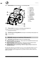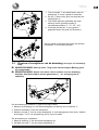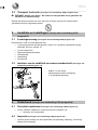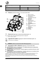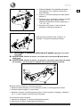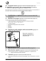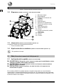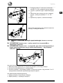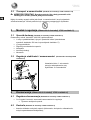
1
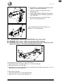
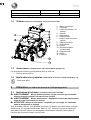
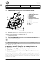
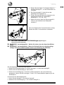
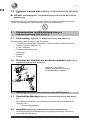
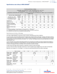
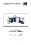
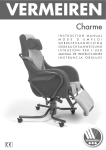
VERMEIREN
V300 - 30°
INSTRUCTION MANUAL
M O D E
D ’ E M P L O I
GEBRUIKSAANWIJZING
GEBRAUCHSANWEISUNG
ISTRUZIONI PER L'USO
MANUAL DE INSTRUCCIONES
INSTRUKCJA OBSŁUGI
V300 30°
2012-08
V300 30° - Additions to manual V300
1
Product description (refer to manual V300 paragraph 1)
1.1
Technical specifications (add to manual V300 paragraph 1.1)
Technical terms below are valid for the wheelchair in standard settings. If other footrest / arm
support or other accessories are used, the tabulated values will change.
Make
Vermeiren
Address
Vermeirenplein 1/15, B-2920 Kalmthout
Type
Manual wheelchair
Model
V300 30°
Maximum occupant mass
130 kg
Description
Min.
Max.
Overall length with legrest
1040 mm
Effective seat width
390 mm
420 mm
440 mm
460 mm
480 mm
500 mm
Overall width (depends on the seat
width)
590 mm
620 mm
640 mm
660 mm
680 mm
700 mm
Folded length
1020 mm
Folded width
310 mm
Folded height
910 mm
Total mass
17,7 kg
Mass of heaviest part
10 kg
Static stability downhill
10° (in standard configuration)
Static stability uphill
2°
Static stability sideways
18° (in standard configur ation)
Obstacle climbing
60 mm
Seat plane angle
0°
10°
Effective seat depth
440 mm
520 mm
Seat surface height at front edge
440 mm
530 mm
5°
35°
Backrest angle
Backrest height
400 mm
Distance between footrest and seat
420 mm
Angle between seat and footrest
Distance between armrest and seat
5°
25°
220 mm
240 mm
Front location of armrest structure
410 mm
Handrim diameter
535 mm
Horizontal location of axle (deflection)
1,27 mm
Minimum turning radius
1500 mm
Diameter Krypton PU Rear wheels
22"
Tyre pressure, rear (driving) wheels
200 mm
Tyre pressure, steering wheels
Storage and use humidity
24"
Max. 3.5 bar
Diameter Krypton PU steering wheels
Storage and use temperature
61,04 mm
Max. 2.5 bar
+ 5 °C
+ 41 °C
30%
70%
We reserve the right to introduce technical changes. Measurement tolerance ± 15 mm / 1,5 kg / °
Table 1: Technical specifications V300 30°
Page 1
V300 30°
2012-08
1.2
Drawing (change paragraph 1.3
manual V300)
1
2
3
4
5
6
7
= Push bar
= Handles
= Lever back inclination
= Backrest
= Armrests
= Arm supports
= Driving wheels (rear
wheels)
8 = Hand rims
9 = Tip cap
10 = Brakes
11 = Steering wheels (front
wheels)
12 = Footrests
13 = Seat
14 = Cross
1.3
Accessories (add to manual V300 paragraph 1.4)
The following accessories are available for the V300 30°:
• Drum brakes (B74)
1.4
Explanation of symbols (add to manual V300 paragraph 1.6)
Not crash-tested
2
Use (refer to manual V300 paragraph 2)
2.1 Backrest inclination (add to manual V300)
L WARNING: Risk of tipping over – Be aware that the stability decreases when
L
L
backrest is adjusted backwards.
WARNING: Risk of injury – Apply the parking brakes before adjusting the
backrest.
CAUTION: Chance of pinching – Do not place your fingers, clothes between the
adjustment mechanism.
With the model V300 30° it is possible to set the b ackrest backwards with a maximum
inclination of 30° (4 different positions: steps 10 °). Be sure that the patient sits in the chair
when the attendant shall perform the back adjusting and that the wheelchair does not tip
over.
Page 2
V300 30°
2012-08
1. Pull handle on both sides towards the grab
handle to adjust the backrest.
2. The pen Ⓐ comes out the groove of the
toothed plate Ⓑ.
3. Pull both back tubes backwards continuously
to the desired position (4 different positions: 5°
- 15° - 25° - 35°).
4. Check that the pen Ⓐ is well fixed in the
groove of the toothed plate Ⓑ.
If your wheelchair features drum brakes, the
handles are used as brakes.
2.2 Mounting or removing of push bar (add to manual V300)
L WARNING: Risk of injury - Make sure that buttons Ⓐ is tightened.
L WARNING: Risk of injury - When equipped with the push bar, the push bar shall
always be mounted (→ to increase the stability of the back).
The mounting of the push bar Ⓑ is done as follows:
1. Mount the push bar Ⓑ with the starknob Ⓐ in the left hand-grip.
2. Swing the push bar Ⓑ to the right.
3. Mount hook Ⓒ over the right hand-grip Ⓓ as shown on the drawing. Use holes
adjust the tension of the backrest.
To take off the Push bar:
1. Loosen the starknob Ⓐ on the right hand-grip.
2. Remove hook Ⓒ from the right hand-grip Ⓓ.
Page 3
or
to
V300 30°
2012-08
2.3 Transport in the car (add to manual V300 paragraph 2.14)
L DANGER: Risk of injury – The wheelchair is not suited for use as a seat in a
motor vehicle.
Never use your wheelchair as a seat in an automobile or other vehicle. The wheelchair shall
be marked with following symbol.
3
Installation and adjustment (refer to manual V300 paragraph 3)
3.1
Manner of delivery (add to manual V300 paragraph 3.2)
The Vermeiren V300 30° shall be delivered with:
• 1 frame with arm supports, rear and front wheels (standard delivery
seat height: 500 mm, seat angle: 5°)
• 1 pair footrests
• Back adjusting mechanism
• Tools
• Manual
• Accessories
3.2
Adjusting the stability and the maneuverability (add to manual V300
paragraph 3.8)
Axle block in most backwards
position, anti-tipping is standard
available.
4
Maintenance (refer to manual V300 paragraph 4)
4.1
Regular Maintenance (add to manual V300 paragraph 4.1)
•
4.2
•
Every 8 weeks: inspection and possibly lubricating or adjusting from
Backrest inclination system
Inspection (add to manual V300 paragraph 4.4)
Check the functioning of the backrest inclination (locking, load, deformation, wear
caused by loads).
Page 4
V300 30°
2012-08
V300 30° - Supplément du manuel
du V300
1
Description du produit (se référer au manuel du V300
paragraphe 1 )
1.1
Caractéristiques techniques (complément du manuel du V300 paragraphe
1.1)
Les indications techniques ci-dessous sont valides pour le fauteuil roulant avec ses réglages
standard. En cas d'utilisation d'autres repose-pieds/repose-bras ou autres accessoires, les
valeurs indiquées sont modifiées.
Marque
Vermeiren
Adresse
Vermeirenplein 1/15, B-2920 Kalmthout
Type
Fauteuil roulant manuel
Modèle
V300 30°
Poids max. du patient
130 kg
Description
Min.
Longueur totale avec repose-jambe
Max.
1040 mm
Largeur d'assise efficace
390 mm
420 mm
440 mm
460 mm
480 mm
500 mm
Largeur totale (en fonction de la largeur
d'assise)
590 mm
620 mm
640 mm
660 mm
680 mm
700 mm
Longueur plié
1020 mm
Largeur plié
310 mm
Hauteur plié
910 mm
Masse totale
17,7 kg
Masse de la partie la plus lourde
10 kg
Stabilité statique en descente
10° (en configuratio n standard)
Stabilité statique en montée
2°
Stabilité statique latérale
18° (en configuration standard)
Passage d'obstacle
60 mm
Angle du plan d'assise
0°
10°
Profondeur d'assise efficace
440 mm
520 mm
Hauteur de la surface d'assise sur le bord
avant
440 mm
530 mm
5°
35°
Angle du dossier
Hauteur du dossier
400 mm
Distance entre le repose-pied et le siège
420 mm
Angle entre le repose-pied et le siège
5°
25°
Distance entre l'accoudoir et le siège
220 mm
240 mm
Emplacement avant de la structure des
accoudoirs
410 mm
Diamètre de la main-courante
535 mm
Emplacement horizontal de l'essieu (flèche)
1,27 mm
Diamètre de braquage minimum
61,04 mm
1500 mm
Diamètre des roues arrière Krypton PU
22"
Pression des pneus, roues arrière (motrices)
24"
Max. 3,5 bars
Diamètre des roues directrices Krypton PU
200 mm
Pression des pneus, roues directrices
Max. 2,5 bars
Page 1
V300 30°
2012-08
Température de stockage et d'utilisation
Humidité de stockage et d'utilisation
+ 5 °C
+ 4 1 °C
30%
70%
Nous nous réservons le droit d’apporter des modifications techniques. Tolérance de mesures ± 15 mm / 1,5 kg / °.
Tableau 1 : Spécifications techniques V300 30°
1.2
Schéma (remplace le paragraphe 1.3 du manuel du V300)
1 = Barre de poussée
2 = Poignées
3 = Levier d'inclinaison du
dossier
4 = Dossier
5 = Manchettes
6 = Repose-bras
7 = Roues motrices (roues
arrière)
8 = Mains-courantes
9 = Anti-bascule
10 = Freins
11 = Roues directrices
(roues avant)
12 = Repose-pieds
13 = Siége
14 = Traverse
1.3
Accessoires (complément du manuel du V300 paragraphe 1.4)
Les accessoires suivants sont disponibles pour le V300 30°:
• Freins à tambour (B74)
1.4
Explication des symboles (complément du manuel du V300 paragraphe 1.6)
Crash-test: NON
2
Utilisation (se référer au manuel du V300 paragraphe 2)
2.1 Inclinaison du dossier (complément du manuel du V300)
L AVERTISSEMENT : Risque de basculement – Soyez conscient que la stabilité
diminue lorsque le dossier est basculé vers l'arrière.
L AVERTISSEMENT : Risque de blessures – Appliquez les freins de stationnement
avant de régler l'inclinaison du dossier.
L ATTENTION : Risque de pincement – Ne placez pas vos doigts, les vêtements
entre du mécanisme de réglage.
Avec le modèle V300 30°, il est possible de bascule r le dossier vers l'arrière avec un angle
maximum de 30° (4 positions différentes: palier de 10°). Assurez-vous que le patient est
assis dans le fauteuil lorsque l'accompagnateur fait basculer le dossier vers l'arrière et
s'assure que le fauteuil roulant ne se renverse.
Page 2
V300 30°
2012-08
1. Tirez le levier
des deux côtés en direction de
pour régler le dossier.
la poignée
2. Le plot Ⓐ sort de la rainure de la plaque
dentée Ⓑ.
3. Tirez les deux conduits du dossier
progressivement vers l'arrière jusqu'à la
position désirée (4 positions différentes: 5° 15° - 25° - 35°).
4. Vérifier que le plot Ⓐ soit bien fixé dans la
rainure de la plaque dentée Ⓑ.
Lorsque le fauteuil roulant est équipé de freins à
tambour, les poignées sont
utilisées pour freiner.
2.2
Montage ou démontage de la barre de poussée (complément du
manuel du V300)
L AVERTISSEMENT : Risque de blessures - Assurez-vous que les boutons Ⓐ sont
correctement serrés.
L AVERTISSEMENT : Risque de lésion - Si le fauteuil roulant dispose d'une barre
du poussoir, elle doit toujours être montée ( → afin d'augmenter la stabilité).
Le montage de la barre de poussée Ⓑ s'effectue comme suit:
1. Fixez la barre du poussoir Ⓑ avec le bouton à croisillon Ⓐ sur la poignée de gauche.
2. Tournez la barre du poussoir Ⓑ vers la droite.
3. Fixez le crochet Ⓒ sur la poignée de droite Ⓓ comme indiqué sur le dessin. Utiliser les
ou
pour ajuster la tension du dossier.
trous
Pour supprimer la barre du poussoir :
1. Détachez la vis Ⓐ au niveau de la poignée droite.
2. Enlevez le crochet Ⓒ de la poignée droite Ⓓ.
Page 3
V300 30°
2012-08
2.3 Transport en voiture (complément du manuel du V300 paragraphe 2.14)
L DANGER : Risque de lésion - Le fauteuil ne convient pas pour être utilisé comme
un siège dans un véhicule motorisé.
N'utilisez jamais le fauteuil roulant comme un siège dans une voiture ou dans un autre
véhicule. Le fauteuil roulant est marqué avec le symbole suivant :
3
Installation et réglage (se référer au manuel du V300 paragraphe
3)
3.1
Mode de livraison (complément du manuel du V300 paragraphe 3.2)
Le Vermeiren V300 30° doit être livré avec :
• 1 châssis avec repose-bras, roues avant et arrière (fourniture standard
hauteur du siège : 500 mm, angle du siège : 5°)
• 1 paire de repose-pieds
• Système de réglage du dossier
• Outils
• Mode d’emploi
• Accessoires
3.2
Réglage de la stabilité et de la manoeuvrabilité (complément du
manuel du V300 paragraphe 3.8)
Bloc d'essieu en arrière
position, roues anti-bascule
sont livrable standardément.
4
Maintenance (se référer au manuel du V300 paragraphe 4)
4.1
Maintenance régulière (complément du manuel du V300 paragraphe 4.1)
•
4.2
•
Toutes les 8 semaines : inspection et éventuellement lubrification et réglage de
Système de réglage du dossier
Inspection (complément du manuel du V300 paragraphe 4.4)
Contrôlez le fonctionnement des inclinaison du dossier (verrouillage, charge,
déformation, usure liée aux charges).
Page 4
V300 30°
2012-08
V300 30° - Aanvullingen op de
handleiding V300
1
Productomschrijving (Verwijs naar handleiding V300 paragraaf 1)
1.1
Technische specificaties (toevoegen aan handleiding V300 paragraaf 1.1)
Onderstaande technische gegevens zijn geldig voor de rolstoel in standaard instellingen.
Wanneer er andere voetsteunen / armsteunen of andere accessoires worden gebruikt,
worden de opgegeven waarden gewijzigd.
Merk
Vermeiren
Adres
Vermeirenplein 1/15, B-2920 Kalmthout
Type
Manuele rolstoel
Model
V300 30°
Maximale massa gebruiker
130 kg
Beschrijving
Min.
Totale lengte inclusief voetsteun
Max.
1040 mm
Effectieve zitbreedte
390 mm
420 mm
440 mm
460 mm
480 mm
500 mm
Totale breedte (afhankelijk van de zitbreedte)
590 mm
620 mm
640 mm
660 mm
680 mm
700 mm
Lengte dichtgevouwen
1020 mm
Breedte dichtgevouwen
310 mm
Hoogte dichtgevouwen
910 mm
Totaal gewicht
17,7 kg
Gewicht zwaartste onderdeel
10 kg
Statische stabiliteit bergaf
10° (in standaard configuratie)
Statische stabiliteit bergop
2°
Statische stabiliteit zijwaarts
18° (in standaard c onfiguratie)
Maximum hoogte hindernis
60 mm
Zithoek
0°
10°
Effectieve zitdiepte
440 mm
520 mm
Zithoogte aan voorzijde
440 mm
530 mm
5°
35°
Rughoek
Rughoogte
400 mm
Afstand tussen zit en voetsteun
420 mm
Hoek tussen zit en voetsteun
Afstand tussen armsteun en zit
5°
25°
220 mm
240 mm
Afstand voorzijde armsteun
410 mm
Diameter aandrijfhoepel
535 mm
Horizontale afstand van de as (uitwijking)
1,27 mm
Minimale draaicirkel
61,04 mm
1500 mm
Diameter Krypton PU achterwielen
22"
Bandendruk, achter (aandrijf)wielen
24"
Max. 3,5 bar
Diameter Krypton PU stuurwielen
200 mm
Bandendruk, stuurwielen
Max. 2,5 bar
Opslag en gebruikstemperatuur
Opslag en gebruiksluchtvochtigheid
+ 5 °C
+ 41 °C
30%
70%
We behouden ons het recht voor om technische wijzigingen te introduceren. Meettolerantie ± 15 mm / 1,5 kg / °
Tabel 1: Technische specificaties V300 30°
Pagina 1
V300 30°
2012-08
1.2
Onderdelen (Verander paragraaf 1.3 in handleiding V300)
1 = Duwstang
2 = Handvaten
3 = Hendel voor
ruginclinatie
4 = Rug
5 = Armleggers
6 = Armsteunen
7 = Aandrijfwielen
(achterwielen)
8 = Grijphoepels
9 = Trapdop
10 = Remmen
11 = Stuurwielen
(voorwielen)
12 = Voetsteunen
13 = Zit
14 = Kruis
1.3
Accessoires (toevoegen aan handleiding V300 paragraaf 1.4)
Volgende accessoires zijn beschikbaar voor de V300 30°:
• Trommelremmen (B74)
1.4
Verklaring van desymbolen (toevoegen aan handleiding V300 paragraaf 1.6)
Niet gecrashtest
2
Gebruik (Verwijs naar handleiding V300 paragraaf 2)
2.1 Inclinatie van de rug (toevoegen aan handleiding V300)
L WAARSCHUWING: Kantelgevaar – Denk eraan dat de stabiliteit toeneemt als de
rug naar achteren wordt gekanteld.
L WAARSCHUWING: Gevaar voor letsel – Zorg ervoor dat de remmen van de
L
rolstoel aangetrokken zijn voordat U de rug inclinatie versteld.
VOORZICHTIG: Kans op beknelling - Plaats Uw vingers, kledij niet tussen het
verstelmechanisme.
Met het model V300 30° is het mogelijk om de rug, m et een maximale inclinatie van 30° (4
verschillende posities: stappen van 10°), naar acht eren te kantelen. Zorg ervoor dat de
patiënt in de rolstoel zit als de begeleider de rug inclinatie versteld en dat de rolstoel niet
achter over kantelt.
Pagina 2
V300 30°
2012-08
1. Trek de hendel
aan beide kanten naar de
handgreep
om de rughoek te verstellen.
2. De pen Ⓐ komt uit de groef van de plaat met
uitstulpingen Ⓑ.
3. Trek beide rugbuizen geleidelijk aan naar
achteren tot de gewenste positie (4
verschillende posities: 5° - 15° - 25° - 35°).
4. Controleer dat de pen Ⓐ terug goed is
gepositioneerd in de groef van de plaat Ⓑ.
Als de rolstoel trommelremmen heeft; dan worden
als remmen gebruikt.
de hendels
2.2
Plaatsen of verwijderen van de duwstang (toevoegen aan handleiding
V300)
L WAARSCHUWING: Kans op letsel - Zorg ervoor dat de knoppen Ⓐ terug goed
zijn vastgemaakt.
L WAARSCHUWING: Gevaar voor letsel - Als de rolstoel over een duwstang
beschikt, dient deze altijd te worden gemonteerd ( → ter verhoging van de
stabiliteit).
Om de duwstang te monteren Ⓑ gaat U als volgt te werk:
1. Monteer de duwstang Ⓑ in de linkse handgreep met behulp van de sterknop Ⓐ .
2. Draai de duwstang Ⓑ naar de rechterkant.
3. Monteer de haak Ⓒ over de rechte handgreep Ⓓ zoals aangegeven in de figuur. Gebruik
of
om de spanning van de rug in te stellen.
de boringen
Om de duwstang te verwijderen:
1. Maak de sterknop Ⓐ aan de rechtse handgreep los.
2. Verwijder de haak Ⓒ van de rechtse handgreep Ⓓ.
Pagina 3
V300 30°
2012-08
2.3 Transport in de auto (toevoegen aan handleiding V300 paragraaf 2.14)
L GEVAAR: Gevaar voor letsel – De rolstoel is niet geschikt om te gebruiken als
een zit in een motorvoertuig.
Gebruik de rolstoel nooit als een zit in een auto of ander voertuig. De rolstoel wordt
gemarkeerd met het volgende symbool:
3
Installatie en instellingen (Verwijs naar handleiding V300
paragraaf 3)
3.1
Leveringsomvang (toevoegen aan handleiding V300 paragraaf 3.2)
De Vermeiren V300 30° wordt geleverd met:
• 1 frame gemonteerd met armsteunen, achter- en voorwielen (standaard levering
zithoogte: 500 mm, zithoek: 5°)
• 1 paar voetsteunen
• Rugverstellingsmechanisme
• Gereedschap
• Handleiding
• Accessoires
3.2
Instellen van de stabiliteit en manouvreerbaarheid (toevoegen aan
handleiding V300 paragraaf 3.8)
Asblok in de meest
achterwaartse positie, anti-tipping
is standaard aanwezig.
4
Onderhoud (Verwijs naar handleiding V300 paragraaf 4)
4.1
Periodiek onderhoud (toevoegen aan handleiding V300 paragraaf 4.1)
•
4.2
•
Om de 8 weken: nakijken en eventueel smeren of afstellen van
Systeem voor ruginclinatie
Inspectie (toevoegen aan handleiding V300 paragraaf 4.4)
Controle op de werking van de ruginclinatie (vergrendeling, belasting, vervorming,
slijtage door belasting)
Pagina 4
V300 30°
2012-08
V300 30° - Ergänzungen zur
Gebrauchsanweisung V300
1
Produktbeschreibung (Bezug zur Gebrauchsanweisung V300,
Kapitel 1)
1.1
Technische Daten (Ergänzung zur Gebrauchsanweisung V300, Kapitel 1.1)
Die im Folgenden aufgeführten technischen Daten gelten für einen Rollstuhl in der
Standardkonfiguration. Wurden eine Fußplatte und/oder eine Armauflage oder anderes
Zubehör montiert, ändern sich die in der Tabelle aufgeführten Werte.
Hersteller
Vermeiren
Adresse
Vermeirenplein 1/15, B-2920 Kalmthout
Typ
Manueller Rollstuhl
Modell
V300 30°
Max. zulässiges Gewicht des
Rollstuhlfahrers
130 kg
Beschreibung
Min.
Gesamtlänge mit Beinstütze
Max.
1040 mm
Effektive Sitzbreite
390 mm
420 mm
440 mm
460 mm
480 mm 500 mm
Gesamtbreite (abhängig von der Sitzbreite)
590 mm
620 mm
640 mm
660 mm
680 mm 700 mm
Länge zusammengeklappt
1020 mm
Breite zusammengeklappt
310 mm
Höhe zusammengeklappt
910 mm
Gesamtgewicht
17,7 kg
Gewicht des schwersten Teils
10 kg
Statische Stabilität, bergab
10° (in der Standardko nfiguration)
Statische Stabilität, bergauf
2°
Statische Stabilität, seitwärts
18° (in der Standar dkonfiguration)
Überfahren von Hindernissen
60 mm
Winkel der Sitzfläche
0°
10°
Effektive Sitztiefe
440 mm
520 mm
Höhe der Sitzoberfläche an der Vorderkante
440 mm
530 mm
5°
35°
Rückenlehnenwinkel
Rückenlehnenhöhe
400 mm
Abstand zwischen Fußplatte und Sitz
420 mm
Winkel zwischen Sitz und Fußplatte
Abstand zwischen Armauflage und Sitz
5°
25°
220 mm
240 mm
Vordere Lage der Armauflage
410 mm
Greifreifendurchmesser
535 mm
Horizontale Lage der Achse (Deflektion)
1,27 mm
Kleinster Wenderadius
61,04 mm
1500 mm
Durchmesser der Krypton PU-Hinterräder
22"
Reifendruck, Hinterräder (Antriebsräder)
24"
max. 3,5 bar
Durchmesser der Krypton PU-Lenkräder
200 mm
Reifendruck, Lenkräder
max. 2,5 bar
Temperaturbereich für Lagerung und Nutzung
5 °C
Seite 1
+41 °C
V300 30°
2012-08
Luftfeuchtigkeitsbereich für Lagerung und
Nutzung
30%
70%
Technische Änderungen vorbehalten. Messtoleranzen ± 15 mm / 1,5 kg / °
Tabelle 1: Technische Daten V300 30°
1.2
Komponenten (Änderung Kapitel 1.3, Gebrauchsanweisung V300 )
1 = Schiebestange
2 = Handgriffe
3 = Hebel für Rückenneigung
4 = Rückenlehne
5 = Armauflagen
6 = Armauflagenträger
7 = Antriebsräder (Hinterräder)
8 = Greifreifen
9 = Kipphilfe
10 = Bremsen
11 = Lenkräder (Vorderräder)
12 = Fußstützen
13 = Sitz
14 = Schere
1.3
Zubehör (Ergänzung zur Gebrauchsanweisung V300, Kapitel 1.4)
Folgendes Zubehör ist erhältlich für die Modelle V300 30°:
• Trommelbremsen (B74)
1.4
Positionstypenschild (Ergänzung zur Gebrauchsanweisung V300, Kapitel 1.6)
Nicht durch Crashtest geprüft
2
Verwendung (Bezug zur Gebrauchsanweisung V300, Kapitel 2)
2.1 Rückenkantelung (Ergänzung zur Gebrauchsanweisung V300)
L WARNUNG: Kippgefahr – Beachten Sie, dass die Stabilität sinkt, wenn die
L
L
Rückenlehne nach hinten verstellt wird.
WARNUNG: Verletzungsgefahr! Betätigen Sie vor dem Einstellen der
Rückenlehne die Feststellbremsen.
VORSICHT: Quetschgefahr - Halten Sie Ihre Finger, Kleidungsstücke fern vom
Verstellmechanismus.
Bei dem Modell V300 30° lässt sich die Rückenlehne bis auf einen Winkel von maximal 30°
nach hinten kippen (4 verschiedene Positionen in 10°-Schritten). Stellen Sie sicher, dass der
Patient in dem Stuhl sitzt, wenn der Begleiter die Rückenlehne nach hinten kippt, und dass
der Rollstuhl nicht umkippt.
Seite 2
V300 30°
2012-08
1. Ziehen Sie den Hebel
auf beiden Seiten in
Richtung Handgriff
, um die Rückenlehne zu
verstellen.
2. Der Sicherungsstift Ⓐ hebt sich aus der
Haltekerbe der Zahnplatte Ⓑ.
3. Ziehen Sie beide Rückenrohre langsam in die
gewünschte Position (4 verschiedene
Positionen: 5° - 15° - 25° - 35°).
4. Stellen Sie sicher, dass der Sicherungsstift Ⓐ
sicher in der Haltekerbe der Zahnplatte
versinkt Ⓑ.
Wenn der Rollstuhl über Trommelbremsen verfügt,
zum Bremsen verwendet.
werden die Griffe
2.2
An- oder Abbauen der Schiebestange (Ergänzung zur
Gebrauchsanweisung V300)
L WARNUNG: Verletzungsgefahr – Stellen Sie sicher, dass die Sternräder Ⓐ fest
sitzen.
L WARNUNG: Verletzungsgefahr - Wenn der Rollstuhl über eine Schiebestange
verfügt, muss diese immer montiert werden (zur Erhöhung der Stabilität).
Die Schiebestange Ⓑ wird wie folgt montiert:
1. Setzen Sie die Schiebestange Ⓑ mit dem Sterngriff Ⓐ in den linken Handgriff.
2. Drehen Sie die Schiebestange Ⓑ nach rechts.
3. Setzen Sie die Aufhängung Ⓒ über den rechten Handgriff Ⓓ wie in der Zeichnung
angegeben. Nutzen Sie die Lochungen
oder
für unterschiedliche Spannung in der
Rückenlehne.
So bauen Sie die Schiebestange ab:
1. Lösen Sie die Sterngriff Ⓐ am rechten Handgriff.
2. Entfernen Sie die Aufhängung Ⓒ vom rechten Handgriff Ⓓ.
Seite 3
V300 30°
2012-08
2.3
Transport in einem auto (Ergänzung zur Gebrauchsanweisung V300, Kapitel
2.14)
L GEFAHR: Verletzungsgefahr - Der Rollstuhl eignet sich nicht als Sitz in einem
Kraftfahrzeug.
Der Rollstuhl darf nicht als Sitzplatz in einem PKW oder anderen Fahrzeug verwendet
werden. Der Rollstuhl ist mit dem folgenden Symbol zu kennzeichnen.
3
Zusammenbau und Einstellung (Bezug zur
Gebrauchsanweisung V300, Kapitel 3)
3.1
Lieferumfang (Ergänzung zur Gebrauchsanweisung V300, Kapitel 3.2)
Der Lieferumfang des Vermeiren V300 30° umfasst:
• 1 Rahmen mit Armauflagen, Hinterrädern und Vorderrädern (Standardlieferung
Sitzhöhe: 500 mm; Sitzgestell: 5°)
• 1 Paar Fußstützen
• Rückenlehneneinstellsystem
• Werkzeuge
• Handbuch
• Zubehör
3.2
Einstellen der Stabilität und der Manövrierbarkeit (Ergänzung zur
Gebrauchsanweisung V300, Kapitel 3.8)
Achsblock nach hinten
montiert, Kippschutzvorrichtung
ist standardmäßig erhältlich)
4
Wartung (Bezug zur Gebrauchsanweisung V300, Kapitel 4)
4.1
Regelmäßige Wartung (Ergänzung zur Gebrauchsanweisung V300, Kapitel
4.1)
•
4.2
•
Alle 8 Wochen: Überprüfen und möglicherweise Schmieren oder Anpassen der
folgenden Teile:
Rückenneigungssystem
Inspektion (Ergänzung zur Gebrauchsanweisung V300, Kapitel 4.4)
Funktionsprüfung der Rückenkantelung (Verriegelung, Belastung, Verformung,
Verschleiß durch Belastung).
Seite 4
V300 30°
2012-08
V300 30° - In aggiunta al manuale
della V300
1
Descrizionedel prodotto (riferirsi al manuale della V300
paragrafo 1)
1.1
Specifiche tecniche (aggiungere al manuale della V300 paragrafo 1.1)
I termini tecnici riportati di seguito sono applicabili alla carrozzina con configurazione
standard. Se sono utilizzati altri poggiapiedi/ poggiabraccia o accessori, i valori in tabella
cambiano.
Produttore
Vermeiren
Indirizzo
Vermeirenplein 1/15, B-2920 Kalmthout
Tipo
Carrozzina manuale
Modello
V300 30°
Peso massimo dell'occupante
130 kg
Descrizione
Min.
Lunghezza complessiva con bracciolo
Max.
1040 mm
Larghezza effettiva del sedile
390 mm
420 mm
440 mm
460 mm
480 mm
500 mm
Larghezza complessiva (in base alla
larghezza del sedile)
590 mm
620 mm
640 mm
660 mm
680 mm
700 mm
Lunghezza ripiegata
1020 mm
Larghezza ripiegata
310 mm
Altezza ripiegata
910 mm
Peso totale
17,7 kg
Massa della parte più pesante
10 kg
Stabilità statica in discesa
10° (in configurazione standard)
Stabilità statica in salita
2°
Stabilità statica laterale
18° (in configurazione standard)
Superamento degli ostacoli
60 mm
Inclinazione del piano del sedile
0°
10°
Profondità effettiva del sedile
440 mm
520 mm
Altezza della superficie del sedile all'estremità
anteriore
440 mm
530 mm
5°
35°
Inclinazione dello schienale
Altezza dello schienale
400 mm
Distanza tra poggiapiedi e sedile
420 mm
Angolazione tra sedile e poggiapiedi
Distanza tra braccioli e sedile
5°
25°
220 mm
240 mm
Posizione anteriore della struttura del
bracciolo
410 mm
Diametro dei corrimano
535 mm
Posizione orizzontale dell'asse (deflessione)
1,27 mm
Raggio di sterzata minimo
61,04 mm
1500 mm
Diametro delle ruote posteriori in PU kripton
22"
24"
Pressione di gonfiaggio pneumatici, ruote
motrici/posteriori
Max. 3,5 bar
Diametro delle ruote direttrici in PU kripton
200 mm
Pagina 1
V300 30°
2012-08
Pressione di gonfiaggio pneumatici, ruote
direttrici
Max. 2,5 bar
Temperatura per utilizzo e conservazione
Umidità per utilizzo e conservazione
+ 5 °C
+ 4 1 °C
30%
70%
La casa produttrice si riserva il diritto di apportare modifiche tecniche. Tolleranza misurazioni ± 15 mm / 1,5 kg / ° .
Tabella 1: Specifiche tecniche V300 30°
1.2
Schema (cmabiare paragrafo 1.3
del manuale della V300)
1 = Barra di spinta
2 = Manopole di spinta
3 = Impugnature
inclinazione schienale
4 = Schienale
5 = Braccioli
6 = Poggiabraccia
7 = Ruote motrici (ruote
posteriori)
8 = Corrimano
9 = Calotta ribaltamento
10 = Freni
11 = Ruote direttrici (ruote
anteriori)
12 = Poggiapiedi
13 = Seduta
14 = Crociera
1.3
Accessori (aggiungere al manuale della V300 paragrafo 1.4)
Per il modello V300 30° sono disponibili gli access ori seguenti:
• Freni a tamburo (B74)
1.4
Legenda dei simboli (aggiungere al manuale della V300 paragrafo 1.6)
Prove d'urto non effettuate
2
Utilizzo (riferirsi al manuale della V300 paragrafo 2)
2.1 Inclinazione dello schienale (aggiungere al manuale della V300)
L AVVERTENZA: Rischio di ribaltamento - La stabilità diminuisce in proporzione
alla regolazione del sedile all'indietro.
L AVVERTENZA: rischio di lesioni – Prima di regolare lo schienale, bloccare i freni
L
di stazionamento.
ATTENZIONE: rischio di pizzicamento - Prestare attenzione a non mettere le dita,
indumenti lontani dai meccanismo di regolazione.
Il modello V300 30° consente un'inclinazione poster iore massima dello schienale di 30° (4
diverse regolazioni con incrementi di 10°). Durante la regolazione dello schienale,
assicurarsi che il paziente sia seduto nella carrozzina e prestare attenzione al rischio di
ribaltamento.
Pagina 2
V300 30°
2012-08
1. Tirare la maniglia
su entrambi i lati verso
l'impugnatura
per regolare l'inclinazione
dello schienale.
2. Il perno Ⓐ fuoriesce dall'apertura della placca
dentata Ⓑ.
3. Reclinare con un movimento continuo entrambi
i profilati tubolari dello schienale nella
posizione desiderata (4 diverse regolazioni: 5°
- 15° - 25° - 35°).
4. Accertarsi che il perno Ⓐ sia ben fissato
all'apertura della placca dentata Ⓑ.
Nelle carrozzine dotate di freni a tamburo, le
maniglie
vengono utilizzate per frenare,
2.2
Montaggio o rimozione della barra di spinta (aggiungere al manuale
della V300)
L AVVERTENZA: Rischio di lesioni - Accertarsi che le manopole Ⓐ siano fissate
saldamente.
L AVVERTENZA: Rischio di lesioni - Se presente, assicurarsi che la barra di spinta
sia montata (→ per aumentare la stabilità dello schienale della carrozzina).
Montare la barra di spinta Ⓑ nel modo seguente:
1. Montare la barra di spinta Ⓑ con la manopola a stella Ⓐ nell'impugnatura sinistra.
2. Ruotare la barra di spinta Ⓑ verso destra.
3. Montare il morsetto Ⓒsull'impugnatura destra Ⓓ come mostrato nel designo. Utilizzare i
e
per regolare la tensione dello schienale.
fori
Per rimuovere la barra di spinta:
1. Allentare la manopola Ⓐ a stella sull'impugnatura destra.
2. Rimuovere il morsetto Ⓒdall'impugnatura destra Ⓓ.
Pagina 3
V300 30°
2012-08
2.3 Trasporto in auto (aggiungere al manuale della V300 paragrafo 2.14)
L PERICOLO: rischio di lesioni - Non è consentito utilizzare la carrozzina in
sostituzione degli appositi seggiolini per il trasporto in auto.
Non utilizzare mai la carrozzina in sostituzione degli appositi seggiolini in un'automobile o in
altri veicoli. Sulla carrozzina deve essere presente il simbolo seguente:
3
Installazione e regolazione (riferirsi al manuale della V300
paragrafo 3)
3.1
Modalità di consegna (aggiungere al manuale della V300 paragrafo 3.2)
La carrozzina Vermeiren V300 30° può essere dotata di:
• 1 telaio con braccioli, ruote anteriori e posteriori (consegna standard
altezza sedile: 500 mm; Telaio sedile: 5°)
• 1 coppia di pedane
• Meccanismo di regolazione dello schienale
• Attrezzi
• Manuale
• Accessori
3.2
Regolazione della stabilità e della manovrabilità (aggiungere al
manuale della V300 paragrafo 3.8)
Blocco asse posteriore, il
dispositivo antiribaltamento
deve essere disponibile come
standard di serie.
4
Manutenzione (riferirsi al manuale della V300 paragrafo 4)
4.1
Manutenzione regolare (aggiungere al manuale della V300 paragrafo 4.1)
•
4.2
•
Ogni 8 settimane ispezione e possibilmente lubrificazione o regolazione da:
Sistema di inclinazione dello schienale
Controllo (aggiungere al manuale della V300 paragrafo 4.4)
Verifica del funzionamento dei braccioli (bloccaggio, carico, deformazione, usura da
carico).
Pagina 4
V300 30°
2012-08
V300 30 ° - Adiciones al manual V300
1
Descripción del producto (Consulte el manual del V300 párrafo 1)
1.1
Especificaciones técnicas (Añadir al manual V300 el párrafo 1.1)
Las condiciones técnicas indicadas a continuación son válidas para sillas de ruedas de
configuración estándar. En caso de utilizar reposapiés/reposabrazos u otros accesorios
diferentes a los indicados, los valores cambian.
Fabricante
Vermeiren
Dirección
Vermeirenplein 1/15, B-2920 Kalmthout
Tipo
Silla de ruedas manual
Modelo
V300 30°
Peso máximo del ocupante
130 kg
Descripción
Mín.
Longitud total con apoya piernas
Máx.
1040 mm
Anchura útil del asiento
390 mm
420 mm
440 mm
460 mm
480 mm 500 mm
Anchura total (depende de la anchura del
asiento)
590 mm
620 mm
640 mm
660 mm
680 mm 700 mm
Longitud plegada
1020 mm
Anchura plegada
310 mm
Altura plegada
910 mm
Peso total
17,7 kg
Peso de la parte más pesada
10 kg
Estabilidad estática en pendientes
descendentes
10° (con la configuración estándar)
Estabilidad estática en pendientes ascendentes
2°
Estabilidad estática lateral
18° (con la configurac ión estándar)
Superación de obstáculos
60 mm
Ángulo plano del asiento
0°
10°
Profundidad útil del asiento
440 mm
520 mm
Altura de la superficie del asiento en la parte
delantera
440 mm
530 mm
5°
35°
Ángulo del respaldo
Altura del respaldo
400 mm
Distancia entre el reposapiés y el asiento
420 mm
Ángulo entre el asiento y el reposapiés
Distancia entre el reposabrazos y el asiento
5°
25°
220 mm
240 mm
Ubicación delantera del armazón del
reposabrazos
410 mm
Diámetro del aro de propulsión
535 mm
Ubicación horizontal del eje (deflexión)
1,27 mm
Radio de giro mínimo
61,04 mm
1500 mm
Diámetro de ruedas traseras Krypton PUR
22"
Presión de los neumáticos, ruedas traseras (de
tracción)
24"
Máx. 3,5 bares
Diámetro de las ruedas de dirección Krypton
PUR
200 mm
Presión de los neumáticos, ruedas de dirección
Máx. 2,5 bares
Temperatura de almacenamiento y de uso
Humedad de almacenamiento y de uso
Página 1
+ 5 °C
+ 41 °C
30%
70%
V300 30°
2012-08
Nos reservamos el derecho a aplicar modificaciones técnicas. Tolerancia de la medida ± 15 mm/1,5 kg/ ° .
Tabla 1: Especificaciones técnicas V300 30°
1.2
Esquema (Cambiar el párrafo 1.3 del manual del V300)
1 = Barra de empuje
2 = Empuñaduras
3 = Palanca de inclinación del
respaldo
4 = Respaldo
5 = Reposabrazos
6 = Soportes de reposabrazos
7 = Ruedas de tracción (ruedas
traseras)
8 = Aros de propulsión
9 = Tapón del extremo
10 = Frenos
11 = Ruedas de dirección (ruedas
delanteras)
12 = Reposapiés
13 = Asiento
14 = Cruceta
1.3
Accesorios (Añadir al manual V300 el párrafo 1.4)
La V300 30° cuenta con los siguientes accesorios:
• Frenos de tambor (B74)
1.4
Explicación de los símbolos (Añadir al manual V300 el párrafo 1.6)
Sin pruebas de choque
2
Uso (Consulte el manual del V300 párrafo 2)
2.1 Inclinación del respaldo (Añadir al manual V300)
L ADVERTENCIA: Riesgo de vuelco: tenga en cuenta que la estabilidad se reduce
cuando el respaldo está ajustado hacia atrás.
L ADVERTENCIA: Riesgo de lesiones: accione los frenos de estacionamiento
L
antes de ajustar el respaldo.
PRECAUCIÓN: Peligro de pellizco: no meta los dedos o la ropa entre los
mecanismos de ajuste.
En el modelo V300 30° es posible ajustar el respald o hacia atrás con una inclinación
máxima de 30° (4 posiciones diferentes a intervalos de 10°). Asegúrese de que el paciente
está sentado en la silla cuando el ayudante tenga que realizar el ajuste del respaldo, y que
la silla de ruedas no se vuelque.
Página 2
V300 30°
2012-08
1. Tire de las palancas
de ambos lados hacia
las empuñaduras
para ajustar el respaldo.
2. El posicionador Ⓐ sale de la ranura de la placa
dentada Ⓑ.
3. Tire hacia atrás ambos tubos del respaldo
hasta la posición deseada (4 posiciones
diferentes: 5° - 15° - 25° - 35°).
4. Compruebe que el posicionador Ⓐ está fijado
correctamente en la ranura de la placa dentada
Ⓑ.
Si su silla de ruedas dispone de frenos de tambor,
se utilizaran como frenos.
las palancas
2.2 Montaje o extracción de la barra de empuje (Añadir al manual V300)
L ADVERTENCIA: Riesgo de lesiones - asegúrese de que los botones Ⓐ están
apretados.
L ADVERTENCIA: Riesgo de lesiones – Cuando esté equipada con barra de
empuje, ésta siempre deberá montarse (para aumentar la estabilidad del
respaldo).
El montaje de la barra de empuje Ⓑ se realiza del modo siguiente:
1. Monte la barra de empuje Ⓑ con el pomo de estrella Ⓐ en la empuñadura izquierda.
2. Gire la barra de empuje Ⓑ hacia la derecha.
3. Monte el gancho Ⓒ en la empuñadura derecha Ⓓ tal y como se muestra en el dibujo.
Utilice los agujeros
o
para ajustar la tensión del respaldo.
Para retirar la barra de empuje:
1. Afloje el pomo de estrella Ⓐ de la empuñadura derecha.
2. Retire el gancho Ⓒ de la empuñadura derecha Ⓓ.
Página 3
V300 30°
2012-08
2.3 Transporte en coche (Añadir al manual V300 el párrafo 2.14)
L PELIGRO: Riesgo de lesiones; la silla de ruedas no se ha diseñado para su uso
como asiento en un automóvil.
No utilice la silla de ruedas como asiento en un coche u otro vehículo. Debe estar marcada
con el símbolo siguiente.
3
Instalación y ajuste (Consulte el manual del V300 párrafo 3)
3.1
Forma de suministro (Añadir al manual V300 el párrafo 3.2)
La silla Vermeiren V300 30° se entrega con:
• 1 chasis con reposabrazos, ruedas delanteras y traseras (altura del asiento de
suministro estándar: 500 mm; Armazón del asiento: 5°)
• 1 par de reposapiés
• Mecanismo de ajuste del respaldo
• Herramientas
• Manual
• Accesorios
3.2
Ajuste de la estabilidad y la maniobrabilidad (Añadir al manual V300
el párrafo 3.8)
Bloqueo de eje en la mayoría
de posiciones hacia atrás, el
antivuelco está disponible
como estándar.
4
Mantenimiento (Consulte el manual del V300 párrafo 4)
4.1
Mantenimiento periódico (Añadir al manual V300 el párrafo 4.1)
•
4.2
•
Cada 8 semanas: inspeccione y posiblemente engrase o ajuste
Sistema de inclinación del respaldo
Inspección (Añadir al manual V300 el párrafo 4.4)
Verifique el funcionamiento de los sistema de inclinación del respaldo (fijación, carga,
deformación, desgaste causado por las cargas).
Página 4
V300 30°
2012-08
V300 30° - Dodatki do instrukcji V300
1
Opisproduktu (Odnosnik do instrukcji
V300 rozdziału 1)
1.1 Parametry techniczne (Dodatek do instrukcji V300 rozdział 1.1)
Parametry techniczne podane poniżej opisują wózek inwalidzki w konfiguracji standardowej.
Jeśli użytkownik korzysta z innych podnóżków/podłokietników lub innych akcesoriów, wartości będą
się różnić.
Producent
Vermeiren
Adres
Vermeirenplein 1/15, B-2920 Kalmthout
Typ
Ręczny wózek inwalidzki
Model
V300 30°
Maksymalna waga użytkownika
130 kg
Opis
Min.
Długość całkowita z podnóżkiem
Maks.
1040 mm
Szerokość użytkowa siedziska
390 mm
420 mm
440 mm
460 mm
480 mm 500 mm
Szerokość całkowita (zależy od szerokości
siedziska)
590 mm
620 mm
640 mm
660 mm
680 mm 700 mm
Długość po złożeniu
1020 mm
Szerokość po złożeniu
310 mm
Wysokość po złożeniu
910 mm
Waga całkowita
17,7 kg
Waga najcięższej części
10 kg
Stabilność statyczna przy pochyłości
10° (w konfiguracji standardowej)
Stabilność statyczna pod górę
2°
Stabilność statyczna w poprzek
18° (w konfiguracji standardow ej)
Zdolność pokonywania przeszkód
60 mm
Kąt nachylenia siedziska
0°
10°
Głębokość użytkowa siedziska
440 mm
520 mm
Wysokość przedniej krawędzi siedziska
440 mm
530 mm
5°
35°
Kąt nachylenia oparcia
Wysokość oparcia
400 mm
Odległość siedziska od podnóżka
420 mm
Kąt pomiędzy siedziskiem a podnóżkiem
Odległość siedziska od podłokietnika
5°
25°
220 mm
240 mm
Przednia pozycja podłokietnika
410 mm
Średnica obręczy
535 mm
Pozycja osi w poziomie (odchył)
1,27 mm
Minimalny promień skrętu
61,04 mm
1500 mm
Średnica kół tylnych Krypton PU
22"
Ciśnienie w oponach, koła tylne (napędowe)
24"
Maksymalnie 3,5 bara
Średnica kół skrętnych Krypton PU
200 mm
Ciśnienie w oponach, koła skrętne
Maksymalnie 2,5 bara
Temperatura przechowywania i użytkowania
+ 5 °C
+ 41 °C
Wilgotność powietrza do przechowywania i
użytkowania
30%
70%
Producent zastrzega sobie prawo do wprowadzania zmian parametrów technicznych. Tolerancja pomiarów ± 15 mm
/ 1,5 kg / °
Tabela 1: Technical specifications V300 30°
Strona 1
V300 30°
2012-08
1.2
Rysunek (Zmiana rozdziału
1.3 w instrukcji V300)
1 = Uchwyt poprzeczny
2 = Uchwyty
3 = Dźwignia do nachylenia
oparcia
4 = Oparcie
5 = Podłokietniki
6 = Oparcia na dłonie
7 = Koła napędowe (tylne)
8 = Obręcze
9 = Zaślepka
10 = Hamulce
11 = Koła skrętne (przednie)
12 = Podnóżki
13 = Siedzisko
14 = Krzyżak
1.3
Akcesoria (Dodatek do instrukcji
V300 rozdział 1.4)
Dla modelu V300 30° dost ępne są następujące akcesoria:
• Hamulce bębnowe (B74)
1.4
Objaśnienie symboli (Dodatek do instrukcji
V300 rozdział 1.6)
Nie przeprowadzano testów zderzeniowych
2
Sposób użycia (Odnosnik do instrukcji
V300 rozdziału 2)
2.1 Nachylenia oparcia (Dodatek do instrukcji V300)
L OSTRZEŻENIE: Ryzyko przewrócenia — stabilność wózka zmniejsza się wraz z
L
L
odchyleniem oparcia.
OSTRZEŻENIE: Ryzyko odniesienia obrażeń — przed przystąpieniem do
regulacji oparcia należy zacisnąć hamulce postojowe.
PRZESTROGA: Możliwość przyszczypnięcia — nie należy wkładać palców,
odzież z dala od mechanizmu mocowania.
W modelu V300 30° mo żliwa jest regulacja pochylenia oparcia o maksymalny kąt 30° (4
różnych ustawień co 10°). Nalezy upewni ć się, że pacjent siedzi w wózku podczas regulacji
oparcia, oraz że wózek się nie przewróci.
Strona 2
V300 30°
2012-08
1. Pociągnij uchwyt
z obu stron w kierunku
uchwytu
w celu ustawienia tylnego oparcia.
2. Trzpień Ⓐ powinien wyjść z ząbkowanej płyty
Ⓑ.
3. Odchyl oba tylne uchwyty do tyłu; w żądanej
pozycji. (4 różnych ustawień: 5° - 15° - 25° 35°).
4. Sprawdź czy trzpeiń Ⓐ skutecznie blokuje.
Jeśli wózek wyposażony jest w hamulce bębnowe,
uchwyty
służą jako hamulce.
2.2
Montaż i demontaż uchwytu poprzecznego (Dodatek do instrukcji
V300)
L OSTRZEŻENIE: Ryzyko urazu — należy upewnić się, że przycisk Ⓐ są
L
odpowiednio dokręcone.
OSTRZEŻENIE: Ryzyko urazu — w przypadku, gdy wózek został wyposażony w
drążek poprzeczny powinien on być zawsze zamontowany (→ aby zwiększyć
stabilność oparcia).
Aby zamontować uchwyt Ⓑ poprzeczny:
1. Zamontuj uchwyt poprzeczny Ⓑ za pomocą pokrętła Ⓐ do lewego uchwytu.
2. Przechyl uchwyt poprzeczny Ⓑ w prawą stronę.
3. Przymocuj zaczep Ⓒ do prawego uchwytu Ⓓ tak jak na rysunku. Użyj otworów
wyregulowania ustawienia odpowiedniego napiecia oparcia.
Aby zdemontować drążek poprzeczny:
1. Odkręć pokrętło Ⓐ przy prawym uchwycie.
2. Zdejmij zaczep Ⓒ z prawego uchwytu Ⓓ.
Strona 3
do
V300 30°
2012-08
2.3 Transport w samochodzie (Dodatek do instrukcji V300 rozdział 2.14)
L NIEBEZPIECZEŃSTWO: Ryzyko zranienia- Nie należy przewozić osób
siedzących w wózku podczas jazdy samochodem.
Nigdy nie należy uzywać wózka jako fotela w samochodach I innych pojazdach
zmechanizowanych. Wózek powinien być oznaczony następującym symbolem.
3
Montaż i regulacja (Odnosnik do instrukcji
3.1
Sposób dostawy (Dodatek do instrukcji
V300 rozdziału 2)
V300 rozdział 3.2)
Dostarczany wózek Vermeiren V300 30° b ędzie zawierał:
• 1 ramę z podłokietnikami, tylnymi i przednimi kołami (standardowa
wysokość siedziska: 500 mm; kąt nachylenia siedziska: 5°)
• 1 parę podnóżków
• Regulacja mechanizmów oparcia
• Narzędzia
• Instrukcja obsługi
• Akcesoria
3.2
Regulacja stabilności i manewrowości
(Dodatek do instrukcji V300
rozdział 3.8)
Ustawienie bloku osi-ostatnia
pozycja, zabezpieczenie antywywrotowe w standardzie.
4
Konserwacja (Odnosnik do instrukcji
4.1
Regularna konserwacja (Dodatek do instrukcji
•
4.2
•
V300 rozdziału 4)
V300 rozdział 4.1)
Co 8 tygodni: kontrola i ewentualnie smarowanie lub regulacja
Systemu nachylania oparcia
Kontrola (Dodatek do instrukcji
V300 rozdział 4.4)
kontrola działania nachylenia oparcia (blokowanie, obciążenie, odkształcenie,
zużycie spowodowane obciążeniem);
Strona 4
Germany
N.V. Vermeiren N.V.
Vermeirenplein 1 / 15
B-2920 Kalmthout
Tel: +32(0)3 620 20 20
Fax: +32(0)3 666 48 94
website: www.vermeiren.be
e-mail: [email protected]
Vermeiren Deutschland GmbH
Wahlerstraße 12 a
D-40472 Düsseldorf
Tel: +49(0)211 94 27 90
Fax: +49(0)211 65 36 00
website: www.vermeiren.de
e-mail: [email protected]
France
Austria
Vermeiren France S.A.
Z. I., 5, Rue d´Ennevelin
F-59710 Avelin
Tel: +33(0)3 28 55 07 98
Fax: +33(0)3 20 90 28 89
website: www.vermeiren.fr
e-mail: [email protected]
L. Vermeiren Ges. mbH
Winetzhammerstraße 10
A-4030 Linz
Tel: +43(0)732 37 13 66
Fax: +43(0)732 37 13 69
website: www.vermeiren.at
e-mail: [email protected]
Italy
Switzerland
Reatime S.R.L.
Viale delle Industrie 5
I-20020 Arese MI
Tel: +39 02 99 77 07
Fax: +39 02 93 58 56 17
website: www.reatime.it
e-mail: [email protected]
Vermeiren Suisse S.A.
Hühnerhubelstraße 59
CH-3123 Belp
Tel: +41(0)31 818 40 95
Fax: +41(0)31 818 40 98
website: www.vermeiren.ch
e-mail: [email protected]
Poland
The Netherlands
Vermeiren Polska Sp. z o.o
ul. Łączna 1
PL-55-100 Trzebnica
Tel: +48(0)71 387 42 00
Fax: +48(0)71 387 05 74
website: www.vermeiren.pl
e-mail: [email protected]
Vermeiren Nederland B.V.
Domstraat 50
NL-3864 PR Nijkerkerveen
Tel: +31(0)33 2536424
Fax: +31(0)33 2536517
website: www.vermeiren.com
e-mail: [email protected]
Spain
Czech Republic
Vermeiren Iberica, S.L.
Trens Petits, 6. - Pol. Ind. Mas Xirgu.
17005 Girona
Tel: +34 902 48 72 72
Fax: +34 972 40 50 54
website: www.vermeiren.es
e-mail: [email protected]
Vermeiren ČR S.R.O.
Sezemická 2757/2 - VGP Park
193 00 Praha 9 - Horní Počernice
Tel: +420 731 653 639
Fax: +420 596 121 976
website: www.vermeiren.cz
e-mail: [email protected]
R.E.: N.V. Vermeiren N.V., Vermeirenplein 1/15 - 2920 Kalmthout - Belgium – 2012-08- Instruction Manual V300 30°- vC
Belgium