1
FR
MULTIFUOCO VENTILATION KIT
WITH RADIO CONTROL
KIT DE VENTILATION MULTIFUOCO
AVEC TÉLÉCOMANDE
e903 S
IT
UK
FR
ISTRUZIONI PER L’INSTALLAZIONE, USO E MANUTENZIONE
INSTRUCTIONS FOR INSTALLATION, USE AND MAINTENANCE
MANUEL D’INSTALLATION, D’UTILISATION ET D’ENTRETIEN
H07022160 / DT2000391 - 01
English
Italiano
Il libretto istruzioni è parte integrante del prodotto. - The instruction booklet is an integral part of the product. - Le manuel fait partie intégrante du produit.
UK
KIT VENTILAZIONE MULTIFUOCO
CON RADIOCOMANDO
Français
IT
Italiano
Gentile Cliente,
La ringraziamo per aver preferito uno dei nostri prodotti, frutto di lunga esperienza e di una continua ricerca per un
prodotto superiore in termini di sicurezza, affidabilità e prestazioni.
In questo manuale troverà tutte le informazioni ed i consigli utili per poter utilizzare il suo prodotto nel massimo della
sicurezza ed efficienza.
DT2010001-01
INDICAZIONI IMPORTANTI
• Questo libretto istruzioni è stato redatto dal
costruttore e costituisce parte integrante del prodotto.
Le informazioni in esso contenute sono indirizzate
all’acquirente, e a tutte quelle persone che a vario titolo
concorrono all’installazione, all’uso e alla manutenzione
del prodotto.
• Leggete con attenzione le istruzioni e le informazioni
tecniche contenute in questo manuale, prima di
procedere all’installazione, all’utilizzo e a qualsiasi
intervento sul prodotto.
• L’osservanza delle indicazioni contenute nel presente
libretto istruzioni garantisce la sicurezza alle persone e
cose; assicura l’economia di esercizio ed una più lunga
durata di funzionamento.
• Il Gruppo Piazzetta S.p.A. declina ogni responsabilità
per danni causati dalla inosservanza alle norme di
installazione uso e manutenzione indicate nel libretto di
istruzioni, per modifiche del prodotto non autorizzate o
ricambi non originali.
DT2011487-00
• L’attenta progettazione e l’analisi dei rischi fatti dal
Gruppo Piazzetta S.p.A. hanno permesso la realizzazione
di un prodotto sicuro; tuttavia prima di effettuare
qualsiasi operazione, si raccomanda di attenersi
scrupolosamente alle istruzioni riportate nel seguente
documento, e di tenerlo sempre a disposizione.
• L’installazione e l’utilizzo del prodotto devono essere
fatti in conformità con le istruzioni del fabbricante, e
nel rispetto delle normative europee, nazionali e dei
regolamenti locali.
• L’installazione, il collegamento elettrico, la verifica del
funzionamento, la manutenzione e le riparazioni, sono
operazioni che devono essere eseguite esclusivamente
da personale qualificato, autorizzato e in possesso di
adeguata conoscenza del prodotto.
Per i termini, limiti ed esclusioni fare riferimento al certificato di garanzia allegato al prodotto.
Il costruttore nell’intento di perseguire una politica di costante sviluppo e rinnovamento del prodotto può apportare, senza preavviso
alcuno, le modifiche che riterrà opportune.
Questo documento è di proprietà del Gruppo Piazzetta S.p.A.; non può essere divulgato totalmente o in parte a terzi
senza autorizzazione scritta del Gruppo Piazzetta S.p.A. Il Gruppo Piazzetta S.p.A. si riserva i diritti a rigore di legge.
2
H07022160 / DT2000391 - 01
Capitolo
Titolo
Pagina
1.0
Kit ventilazione Multifuoco con radiocomando
4
2.0
Esploso kit ventilazione
5
3.0
Installazione del kit ventilazione
6
4.0
Esempi di allacciamento tubi flessibili
8
5.0
Uso
9
6.0
Manutenzione
10
7.0
Schema elettrico
11
8.0
Risoluzione problemi
12
Questo libretto codice H07022160 / DT2000391 rev. 01 - (12/2008) è composto da 40 pagine.
H07022160 / DT2000391 - 01
3
Italiano
INDICE
DT2010187-00
Italiano
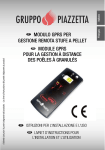
1.0 KIT VENTILAZIONE MULTIFUOCO CON RADIOCOMANDO
DT2011488-00
I monoblocchi Piazzetta, sono predisposti per
l’installazione del “Kit ventilazione Multifuoco con
radiocomando”. Tale sistema, brevettato dal Gruppo
Piazzetta S.p.A. consente il riscaldamento di uno o più
locali in modo omogeneo evitando la stratificazione
dell’aria calda a soffitto.
L’installazione del Kit ventilazione non
comporta un aumento della potenza termica
del monoblocco, bensì il riscaldamento del locale
(o locali) in modo omogeneo, in quanto tale sistema
(che consente l’aspirazione dell’aria dall’alto e uscita
dal basso) crea un ricircolo d’aria che ne impedisce la
stratificazione a soffitto.
Il Kit ventilazione è costituito da: un ventilatore (con
portata di circa 220 m3/h ed una potenza di 47 Watt)
cablato con cavo e scatola radiocomando, sonda PT,
radiocomando portatile con 4 tasti (alimentato da
batterie a basso voltaggio), distanziatori, minuteria di
fissaggio.
Il radiocomando è dotato di un tasto (ON / OFF) che ha
una doppia funzione ossia “accensione /spegnimento”,
un tasto per il passaggio al funzionamento automatico
(AUTO) e due tasti (+/-) che regolano la velocità di
funzionamento del ventilatore (velocità minima V1,
velocità media V2, velocità medio massima V3, velocità
massima V4).
Per identificare la velocità di funzionamento del
ventilatore impostata è sufficiente ascoltare il
numero di bip emessi quando si premono i tasti + e
- del radiocomando (1 bip per ogni incremento di
velocità); quando si spegne manualmente il ventilatore
si udirà un bip lungo che identifica l’avvenuto
spegnimento del sistema.
La sonda permette l’avviamento o l’arresto in
automatico del ventilatore quando la temperatura
raggiunge rispettivamente la soglia di accensione o
quella di spegnimento.
4
H07022160 / DT2000391 - 01
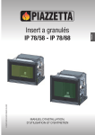
DT2032143-00
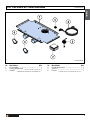
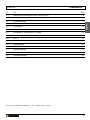
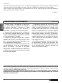
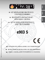
2.0 ESPLOSO KIT VENTILAZIONE
Italiano
Italiano
DT2011508-00
DT2032150-00
Nr.
1
2
3
Descrizione
Kit ventilazione
Scatola radiocomando
Sonda PT
Q.tà
1
1
1
Nr.
4
5
6
Descrizione
Cavo di alimentazione
Spina IEC
Fascetta
H07022160 / DT2000391 - 01
Q.tà
1
1
2
5
Italiano
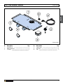
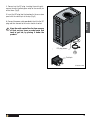
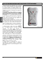
3.0 INSTALLAZIONE DEL KIT VENTILAZIONE
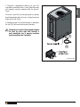
1. Per l’installazione procedere come segue:
- prevedere nelle vicinanze della stufa una presa di
corrente elettrica.
- Alzare la stufa nella parte anteriore e fissare il kit
ventilazione nella zona inferiore della stufa fissandolo
con le viti e le rondelle in dotazione. (Fig. 1)
DT2011512-00
Fig. 1
DT2032152-00
2. Inserire la sonda PT nell’apposito foro per circa 10
cm e bloccarla con la staffa di fissaggio al supporto
ventilatore (Fig. 2).
Fig. 2
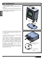
3. Collegare i tubI flessibilI alle bocchette uscita aria
calda prima di inserire il frontalino in ceramica.
Per eventuali o ulteriori bocchette per il riscaldamento
di locali attigui, si possono creare delle diramazioni del
tubo flessibile Ø 75 con gli appositi Y (forniti a richiesta
dal Gruppo Piazzetta S.p.A.); togliere i semitranci
dalla protezione posteriore, quindi far passare il tubo
flessibile.
Nel caso si volesse condurre l’aria anche in ambienti
adiacenti scegliere il percorso più breve limitando così
le dispersioni di calore.
Si raccomanda quindi di non far compiere al tubo
flessibile percorsi troppo lunghi e di isolarlo nel modo
migliore. (Vedere le istruzioni allegate alla stufa).
DT2032153-00
6
H07022160 / DT2000391 - 01
Fig. 3
Italiano
Italiano
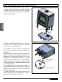
4. Effettuare il collegamento elettrico alla spina IEC
inserendo il fastom della messa a terra (filo giallo-verde)
sulla linguetta centrale superiore delle tre presenti.
(Fig.3)
5. Inserire la spina IEC nel trancio presente nel retro del
pannello posteriore della stufa con la linguetta centrale
rivolta verso l’alto. (Fig.3)
6. Collegare quindi il cavo alimentazione in dotazione
alla spina IEC ed inserirlo nella presa di corrente.
Mantenere la scatola radiocomando lontano
da fonti di calore quali tubi flessibili o
parti metalliche che si possono scaldare
posizionandola sotto il prodotto.
DT2032142-00
DT2032154-00
H07022160 / DT2000391 - 01
7
Italiano
4.0 ESEMPI DI ALLACCIAMENTO TUBI FLESSIBILI
DT2011492-00
Vi illustriamo qui di seguito alcuni esempi di allacciamento e di sistemazione del tubo flessibile a parete e a pavimento
(per una miglior resa è necessario rivestire il tubo flessibile con una guaina isolante adeguata).
8
DT2030168-00
DT2030169-00
DT2030170-00
DT2030171-00
H07022160 / DT2000391 - 01
5.0 USO
Italiano
Italiano
DT2011493-00
Dopo aver dato tensione al kit ventilazione, attendere qualche secondo prima di premere i tasti
del radiocomando al fine di permettere il ceck-up delle schede elettroniche.
Tramite il radiocomando si possono scegliere diversi tipi di impostazioni.
FUNZIONAMENTO AUTOMATICO
Per avviare il ventilatore in funzionamento automatico, procedere come segue:
- Accendere il fuoco,
- premere il tasto AUTO (il numero di bip emessi indica la velocità in cui si trova impostato il ventilatore),
- impostare la velocità desiderata tramite una leggera pressione dei tasti +/- del radiocomando scegliendo tra quattro
diverse velocità di funzionamento (V1 – V2 – V3 – V4),
- il ventilatore si avvia solo quando la sonda rileva la temperatura di accensione,
- lo spegnimento del ventilatore avverrà quando la temperatura rilevata dalla sonda scenderà sotto la soglia
minima,
- in qualsiasi momento è possibile spegnere il ventilatore in funzione cliccando il tasto ON/OFF (il bip lungo identifica
lo spegnimento del sistema) e non si accenderà anche se la sonda non raggiungerà la temperatura di avviamento.
Per riavviare il ventilatore si deve necessariamente premere il tasto “ON/OFF” oppure “AUTO”.
Se il ventilatore si spegne in automatico, ripartirà in tale modalità se la sonda rileva un valore di
temperatura superiore alla soglia di accensione.
FUNZIONAMENTO MANUALE
Per avviare il ventilatore in funzionamento manuale, procedere come segue:
- premere il tasto ON/OFF (il numero di bip emessi indica la velocità in cui si trova impostato il ventilatore),
- impostare la velocità desiderata tramite una leggera pressione dei tasti +/- del radiocomando scegliendo tra quattro
diverse velocità di funzionamento (V1 – V2 – V3 – V4),
- il ventilatore si avvia immediatamente a focolare freddo quando la temperatura rilevata dalla sonda supera il valore
di accensione il tipo di funzionamento si commuta in automatico predefinito e si spegnerà quando la sonda raggiunge
la temperatura di spegnimento,
- in qualsiasi momento è possibile spegnere il ventilatore in funzione cliccando il tasto ON/OFF (il bip lungo identifica
lo spegnimento del sistema).
Se il sistema viene avviato in modalità manuale a focolare freddo e la sonda non rileva la
temperatura necessaria per attivare il funzionamento automatico, il ventilatore continuerà a
funzionare fino a che non si preme il tasto ON/OFF.
IMPOSTAZIONE DEL SET VELOCITA’ PER APPARECCHIO CON CANALIZZAZIONE
A seconda del tipo di canalizzazione, si può scegliere tra due tipi di set velocità:
- il SET 1, per il kit ventilazione con uscita frontale o frontale/posteriore con una breve canalizzazione (set
preimpostato di serie),
- il SET 2, per il kit ventilazione con canalizzazione più lunga.
H07022160 / DT2000391 - 01
9
Italiano
- Per variare l’impostazione da un set all’altro, dopo aver acceso il ventilatore in modalità AUTOMATICA o MANUALE,
è sufficiente tenere premuti contemporaneamente, per circa 3 secondi, i tasti “ON/OFF” e “-” (il segnale acustico in
SET 2 è di 2 bip seguito da i bip della velocità impostata).
- Ripremendo contemporaneamente, per circa 3 secondi, i tasti “ON/OFF” e “-” si ripassa in modalità SET 1 (il
segnale acustico in SET1 è di 1 bip seguito da i bip della velocità impostata).
Esempio: se ci troviamo in SET 1 ed a VELOCITA’ 3 e teniamo premuti contemporaneamente i tasti “ON/OFF” e
“-“ per passare a SET 2 sentiremo prima 2 bip che identificano il nuovo set (SET 2) e poi si udiranno 3 bip che
identificano la velocità impostata (in questo caso VELOCITA’ 3).
Per ritornare in SET 1 basta ripremere contemporaneamente i tasti “ON/OFF” e “-“, in questo caso si udiranno
prima 1 bip (SET 1) e poi 3 bip (VELOCITA’ 3).
Una volta impostato il SET a seconda del Vostro tipo di canalizzazione non è necessario modificarlo di seguito.
Nell’impostazione della velocità di funzionamento (V1 – V2 – V3 – V4), scegliete le velocità più alte per portare in
temperatura il più velocemente possibile i locali da riscaldare; usate velocità più basse per mantenere la temperatura
raggiunta nei locali.
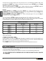
SCHEMA IMPOSTAZIONE VELOCITA’
SET 1
SET 2
VELOCITA’ 1
80 V
115V
VELOCITA’ 2
115 V
150V
VELOCITA’ 3
150 V
185V
VELOCITA’ 4
220 V
220V
NOTA: lo schema indica la tensione con cui funziona la centralina, la portata può variare a seconda del monoblocco
e del tipo di canalizzazione.
MANCA LA TENSIONE ELETTRICA
Nel caso mancasse la tensione elettrica e si fosse in modalità AUTO, al ripristino della stessa il ventilatore ripartirà
alla velocità in cui si trovava prima della mancanza di tensione, solo se la sonda rileva una temperatura superiore al
limite di accensione; nel caso la temperatura fosse inferiore il ventilatore rimane spento e la centralina si posiziona
nell’ultima velocità impostata.
Anche in caso di modalità MANUALE al ripristino della tensione il ventilatore ripartirà alla velocità ultima impostata.
6.0 MANUTENZIONE
DT2011494-00
Periodicamente disinserire il collegamento elettrico del ventilatore e pulirlo dalla polvere che si può accumulare nelle
feritoie della protezione in plastica e nelle palette rotanti.
In caso di malfunzionamento tutti gli interventi sull’apparecchio e sul cablaggio devono essere eseguiti da personale
qualificato.
OGNI INTERVENTO DEVE ESSERE ESEGUITO A CORRENTE DISINSERITA E DA PERSONALE
QUALIFICATO.
10
H07022160 / DT2000391 - 01
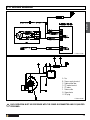
7.0 SCHEMA ELETTRICO
Italiano
Italiano
DT2011513-00
DT2032155-00
A. Ventilatore
B. Morsetto alimentazione
C. Scatola radiocomando
D. Morsetto sonda PT
E. Sonda PT
F. Cavo di alimentazione
G. Filo di terra
H. Presa IEC
DT2032156-00
OGNI INTERVENTO DEVE ESSERE ESEGUITO A CORRENTE DISINSERITA E DA PERSONALE
QUALIFICATO.
H07022160 / DT2000391 - 01
11
Italiano
8.0 RISOLUZIONE PROBLEMI
DT2011496-00
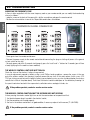
MODIFICA DEL CODICE DI FREQUENZA
In caso ci siano altri apparecchi con il codice di frequenza uguale al Vostro radiocomando potete modificare il canale
di trasmissione agendo come segue:
- Aprire il radiocomando svitando con un cacciavite a stella la vite posta nel retro del coperchio.
- Posizionare i microinterruttori in una delle 16 combinazioni possibili sotto elencate.
DT2032144-00
- Richiudere il coperchio del radiocomando.
- Togliere alimentazione alla scatola radiocomando staccando la spina o interrompendo l’alimentazione agendo
sull’interruttore generale di zona.
- Ridare tensione ed entro 5 secondi premere contemporaneamente i tasti “auto” e “+” per 3 secondi (udirete un bip
che segnala l’avvenuta modifica del codice).
LA SPIA DEL RADIOCOMANDO NON SI ACCENDE
Controllare lo stato di carica della batteria del radiocomando.
In caso di sostituzione procedere come segue: utilizzando un cacciavite a croce di piccole dimensioni togliere la
vite presente nella parte posteriore del radiocomando; quindi mantenendolo capovolto togliere il guscio posteriore.
A questo punto sostituirla con una nuova, tipo A 23 12V, prestando attenzione a non invertire la polarità (tipo di
batteria e polarità sono comunque riportati anche sulla scheda del radiocomando come visibile nella foto sopra).
Quindi richiudere il radiocomando e smaltire la batteria vecchia gettandola negli appositi contenitori presenti presso
i supermercati, centri di raccolta, isole ecologiche, ecc.
Se il problema persiste contattare un rivenditore o centro assistenza.
IL RADIOCOMANDO FUNZIONA MA IL RICEVITORE NON RISPONDE
Se schiacciando il tasto del radiocomando la spia si accende ma il ricevitore non risponde controllare:
1. che la spina di alimentazione sia inserita nella presa di corrente;
2. che i connettori siano correttamente inseriti;
3. il fusibile della scatola radiocomando sia integro, eventualmente sostituirlo con uno nuovo (T1,6AL250V).
Se il problema persiste contattare un rivenditore o centro assistenza.
12
H07022160 / DT2000391 - 01
H07022160 / DT2000391 - 01
Dear Customer,
Thank you for having chosen one of our products, which is the result of years of experience and continuous research
aimed at making a superior product in terms of safety, reliability and performance.
This booklet contains information and advice for safe and efficient use of your product.
English
DT2010001-01
IMPORTANT INFORMATION
• This instruction booklet has been prepared by the
manufacturer and is an integral part of the product. The
information contained in it is intended for the purchaser
and for anyone involved in the installation, use and
maintenance of the product.
• Read the instructions and the technical information
contained in this booklet carefully before proceeding
with installation, use or any repairs.
• The observance of the instructions and technical
information in this instruction booklet guarantees the
safety of persons and property; it also ensures more
efficient operation and an increased lifespan.
• Gruppo Piazzetta S.p.A. cannot be held responsible
for damage or injury due to failure to comply with the
instructions for installation, use and maintenance given
in this booklet, or due to unauthorised alterations or to
the use of other than original spare parts.
DT2011487-00
• The careful design and risks analysis conducted by
Gruppo Piazzetta S.p.A. have permitted the manufacture
of a safe product; nevertheless before conducting any
operation, it is recommended that the instructions
described in the following document be scrupulously
adhered to and that the document always be kept
readily available.
• Appliance installation and use must conform with the
manufacturer’s instructions as well as with European
and national legislation and local regulations.
• Installation, electrical connection, checks, maintenance
and repairs are operations which must be carried out
exclusively by qualified and authorised personal with
specialised knowledge of the product.
See the guarantee certificate enclosed with the product for the terms, limitations and exclusions. In line with its policy of constant
product improvement and renewal, the manufacturer may make changes without notice.
This document is the property of Gruppo Piazzetta S.p.A.; no part of it may be disclosed to third parties without the
written permission of Gruppo Piazzetta S.p.A. All rights reserved by Gruppo Piazzetta S.p.A.
14
H07022160 / DT2000391 - 01
CONTENTS
DT2010187-00
Title
Page
1.0
Multifuoco ventilation kit with radio control
16
2.0
Exploded views
17
3.0
Installation
18
4.0
Examples of connection for hoses
20
5.0
Use
21
6.0
Maintenance
22
7.0
Wiring diagram
23
8.0
Troubleshooting
24
This booklet code H07022160 / DT2000391 rev. 01 - (12/2008) comprises 40 pages.
H07022160 / DT2000391 - 01
15
English
Italiano
Cap.
English
1.0 MULTIFUOCO VENTILATION KIT WITH RADIO CONTROL
DT2011488-00
The fireplaces Piazzetta are predisposed for the
installation of the “Multifuoco Ventilation kit with radio
control”. This system, patented by Gruppo Piazzetta
S.p.A., makes it possible to heat one or more rooms
uniformly thus preventing layering of hot air near the
ceiling.
Installation of the fan kit does not entail an
increase in the heat output of the appliance, but
rather the heating of the room (or rooms) uniformly in so
far that this system (that allows aspiration from above
and exhaust from below) creates a recycling of hot air
which impedes ceiling stratification.
The Fan kit is provided of: a ventilation fan (which has
an airflow of approximately 220 m3/ h, power capacity
of 47 Watts) wired withy cable and radio control box, PT
probe, portable remote control with 4 buttons (fed by
low-voltage batteries), spacers, fixation elements.
The remote control is equipped with an (ON/OFF) button
which has two functions, i.e. “turning on / turning off”, a
button for switching to automatic operation (AUTO) and
two buttons (+/-) governing the fan operating speed
(minimum speed V1, average speed V2, maximum
average speed V3, maximum speed, V4).
To identify the operating speed setting of the fan, simply
listen to the number of beeps emitted when the + and
- buttons of the remote control are pressed (1 beep for
each increase in speed), when manually shutting off
the fan, a long beep is heard which signifies that the
system has been turned off.
The probe allows the fan to automatically start and stop
when the temperature reaches the turn-on and turn-off
thresholds.
16
H07022160 / DT2000391 - 01
DT2032143-00
2.0 EXPLODED VIEWS
English
Italiano
DT2011508-00
DT2032150-00
N.
1
2
3
Description
Ventilation kit
Radio-control box
PT probe
Q.ty
1
1
1
N.
4
5
6
Description
Power cable
IEC outlet
Clip
H07022160 / DT2000391 - 01
Q.ty
1
1
2
17
3.0 INSTALLATION
DT2011512-00
Fig. 1
English
1. To install, proceed as follows:
- ensure that there is a mains electrical socket near
the stove.
- lift the stove at the front and fit the ventilation kit into
the bottom of the stove securing it with the screws and
washers provided in the kit. (Fig. 1)
Knockouts
DT2032152-00
2. Insert the PT sensor into the relative hole by about
10 cm and use the fixing bracket to secure it to the
fan support (Fig. 2).
Fig. 2
3. Connect the hoses to the hot air outlets before
inserting the ceramic front panel.
If other outlets are required for heating adjoining
rooms, the hose dia. 75 may be branched using the
relative Y elements (supplied by Gruppo Piazzetta
S.p.A. on request); remove the knockouts from the
rear protection panel and then pass the hose through.
To convey air also to adjacent rooms, choose the
shortest route to limit heat loss.
It is advisable to avoid running the hose along very
long routes, and to insulate it properly. (see instructions
accompanying the stove).
Hole for inserting
PT sensor
PT sensor fixing
bracket
DT2032153-00
18
H07022160 / DT2000391 - 01
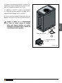
4. Connect up the IEC plug, inserting the earth quickconnect terminal (yellow-green wire) to the central pin
of the three. (Fig.3)
Fig. 3
5. Insert the IEC plug into the knockout in the rear stove
panel with the central pin at the top. (Fig.3)
English
Italiano
6. Connect the power cable provided in the kit to the IEC
plug and then connect to the mains electrical socket.
Keep the radio control box far from sources
of heat, such as hoses or metal parts that
tend to get hot, by placing it under the
product.
IEC plug recess
Earth pin
DT2032154-00
H07022160 / DT2000391 - 01
19
4.0 EXAMPLES OF CONNECTION FOR HOSES
DT2011492-00
English
Here are a few examples showing how to connect and arrange the hose for walls and floors (for better efficiency the
hose must be lagged with adequate insulated sheathing).
20
DT2030168-00
DT2030169-00
DT2030170-00
DT2030171-00
H07022160 / DT2000391 - 01
5.0 USE
DT2011493-00
After having provided power to the fan kit, wait a few seconds before pressing the remote control
buttons to allow the check-up of the electronic boards.
AUTOMATIC OPERATION
To start the fan in the automatic mode, proceed as follows:
- Light the fire,
- press the AUTO button (the number of beeps emitted indicates the speed at which the fan is set),
- set the speed desired pressing the +/- remote control buttons lightly choosing from among four different operating
speeds (V1 – V2 – V3 – V4),
- the fan starts only when the probe detects the turn-on temperature,
- the fan will shut-off when the temperature detected by the probe falls below the minimum threshold,
- the fan in operation can be turned off at any time clicking the ON/OFF button (the long beep signals the shuttingdown of the system) and it will not start-up even if the probe reaches the start-up temperature.
To restart the fan, it’s necessary to press the “ON/OFF” or also the “AUTO” button.
If the fan shuts off automatically, it will start again in the same mode if the probe detects a
temperature reading greater than the turn-on threshold.
MANUAL OPERATION
To start the fan in the manual operation mode, proceed as follows:
- press the ON/OFF button (the number of beeps emitted indicates the speed at which the fan is set),
- set the speed desired pressing the +/- remote control buttons lightly choosing from among four different operating
speeds (V1 – V2 – V3 – V4),
- the fan starts immediately when the temperature detected by the probe exceeds the turn-on value, the type of
operation commutes to the predefined automatic mode and will shut down when the probe reaches the shutdown
temperature,
- the fan in operation may be shut-off at any time clicking the ON/OFF button (the long beep indicates the shutting
down of the system).
If the system comes started in manual modality with cold stove and the probe does not find the
necessary temperature in order to activate the automatic functioning, the fan will continue to
work till that the ON/OFF botton will be pressed.
SETTING THE FAN SPEED
Depending upon type of ductwork, two types of speed settings can be chosen:
SETTING 1, for the fan kit with front or front/rear outlet with a short duct (factory setting for the series);
SETTING 2, for the fan kit with longer ductwork.
H07022160 / DT2000391 - 01
21
English
Italiano
Two types of operations can be selected with the remote control.
English
To change from one setting to another, after having turned on the fan in the AUTOMATIC or MANUAL mode, simply
press down on the “ON/OFF” and “-” buttons simultaneously (the acoustical signal in SETTING 2 consists of 2 beeps
followed by the beeps for the speed setting).
Again simultaneously pressing the “ON/OFF” and “-” buttons switches the system to the SETTING 1 mode (the
acoustical signal in SETTING 1 consists of 1 beep followed by the speed setting beeps).
Example:
if we are in SETTING 1 and at SPEED 3 and we hold the “ON/OFF” and “-“ buttons pressed simultaneously to pass
to SETTING 2 we will initially hear 2 beeps which identify the new setting (SETTING 2) and then 3 beeps will be
heard which identify the speed setting (in this case SPEED 3).
To return to SETTING 1 simply press the “ON/OFF” and “-“ buttons simultaneously again, in this case an initial beep will
be heard (SETTING 1) and then 3 beeps (SPEED 3).
Once having imposed the SETTING according to your type of ductwork, further modifications will not be needed.
When making the operating speed setting(V1 – V2 – V3 – V4), select the highest speed to bring the rooms to be heated to
the desired temperature; use lower speeds to maintain the temperature reached in the room.
SPEED SETTING LAYOUT
SETTING 1
SETTING 2
SPEED 1
80 V
115V
SPEED 2
115 V
150V
SPEED 3
150 V
185V
SPEED 4
220 V
220V
NOTE: the layout indicates the voltage at which the unit operates, the airflow can vary depending upon the fire box
and the type of ductwork.
IF THERE IS NO ELECTRICAL POWER
If electrical power is lost while in the AUTO mode, when power is restored, the fan will start at the speed it was at
before power was lost only if the probe detects a temperature greater than turn-on limit; should the temperature be
lower, the fan remains off and the unit shifts to the speed most recently set.
For the MANUAL mode also, upon restoring power, the fan will start at the speed most recently set.
6.0 MAINTENANCE
DT2011494-00
Disconnect the fan periodically from the power supply and clean the dust that may have been deposited in the slits
in the plastic covering and on the rotating blades.
In the event of a fault, all operations on the appliance and cables must be performed by qualified persons.
EACH OPERATION MUST BE PERFORMED WITH THE POWER DISCONNECTED AND BY QUALIFIED
PERSONNEL.
22
H07022160 / DT2000391 - 01
7.0 WIRING DIAGRAM
English
Italiano
DT2011513-00
DT2032155-00
A.
B.
C.
D.
E.
F.
G.
H.
Fan
Power supply terminal
Radio control box
PT probe terminal
PT probe
Power cable
Ground wire
IEC plug
DT2032156-00
EACH OPERATION MUST BE PERFORMED WITH THE POWER DISCONNECTED AND BY QUALIFIED
PERSONNEL.
H07022160 / DT2000391 - 01
23
8.0 TROUBLESHOOTING
DT2011496-00
English
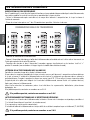
MODIFYING THE FREQUENCY CODE
In there is other equipment with the same frequency code as your remote control you can modify the broadcasting
channel as follows:
- undo the screw on the back of the cover with a philips screw driver and open the remote control.
- Position the microswitches in one of the 16 possible combinations listed below
TRANSMISSION CHANNEL COMBINATIONS
DT2032144-00
- Once again close the remote control cover.
- Remove the power supply to the remote control box disconnecting the plug or shutting off power at the general
cut-out switch for the area.
- Resupply power and within 5 seconds simultaneously press the “auto” and “+” buttons for 3 seconds (you will hear
a beep signifying that the code has been modified).
THE WIRELESS CONTROL LIGHT DOES NOT TURN-ON
Check the status of the wireless’s battery charge control.
In case of replacement proceed as follows: using a small Phillips-head screwdriver, remove the screws in the rear
part of the wireless control; then keeping it inverted, remove the rear shell. At this point replace it with a new, A 23
12V type, taking care not to invert the polarity (battery type and polarity are in any case also described on the wireless
control chart visible in the photo above). Then close the wireless control and dispose of the old battery throwing it in
the special containers located in the supermarkets, collection centres ecological islands, etc.
If the problem persists, contact a vendor service center.
THE WIRELESS CONTROL FUNCTIONS BUT THE RECEIVER DOES NOT RESPOND
If when pressing the wireless control light turns on but the receiver does not respond check that:
1. that electrical power plug is inserted in the electrical socket;
2. that the connectors are inserted properly;
3. the fuse in the wireless control box is in good condition, if necessary replace it with new one (T1.,6AL250V).
If the problem persists, contact a vendor service centre.
24
H07022160 / DT2000391 - 01
H07022160 / DT2000391 - 01
Cher Client,
Nous vous remercions d’avoir choisi l’un de nos produits. Cet appareil est le fruit d’une longue expérience et d’une
recherche continue, afin d’améliorer sans cesse la sécurité, la fiabilité et les performances de nos produits.
Dans ce manuel, vous trouverez toutes les informations et les conseils utiles pour pouvoir utiliser votre produit en
toute sécurité et avec la meilleure efficacité.
DT2010001-01
Français
INDICATIONS IMPORTANTES
• Ce mode d’emploi a été rédigé par le constructeur
et est partie intégrante du produit. Les informations
qu’il contient s’adressent à l’acheteur, et à toutes
les personnes qui, à différents titres, concourent à
l’installation, à l’utilisation et à l’entretien du produit.
• Il convient de lire minutieusement les instructions et
les informations techniques contenues dans le présent
manuel, avant de procéder à l’installation, à l’utilisation
et à toute intervention sur le produit.
• Le respect des indications contenues dans le présent
mode d’emploi garantit la sécurité des personnes et des
biens ; il assure un fonctionnement économique et une
plus longue durée de fonctionnement.
• Le Groupe Piazzetta S.p.A décline toute responsabilité
pour les dommages causés par le non-respect des
normes d’installation, d’utilisation et d’entretien
indiquées dans le mode d’emploi, par des modifications
du produit non autorisées ou par des pièces de rechange
autres que celles d’origine.
DT2011487-00
• La conception exemplaire et l’analyse des risques
effectuées par Gruppo Piazzetta S.p.A. ont permis de
réaliser un produit extrêmement sûr; toutefois, avant
d’engager une quelconque opération, il est recommandé
d’observer scrupuleusement les instructions reportées
dans le présent manuel; celui-ci doit toujours être à
disposition pour pouvoir le consulter en cas de besoin.
• L’installation et l’utilisation du produit doivent être
réalisées conformément aux instructions du fabricant,
et dans le respect des normes européennes, nationales
et des règlements locaux.
• L’installation, le branchement électrique, la vérification
du fonctionnement, l’entretien et les réparations, sont
des opérations qui doivent être effectuées exclusivement
par un personnel qualifié, autorisé et possédant une
connaissance adaptée du produit.
Pour les termes, les limites et les exclusions, reportez-vous au certificat de garantie qui accompagne le produit. Dans le but de
poursuivre une politique de développement constant et de renouvellement du produit, le Fabricant se réserve la faculté d’apporter,
sans préavis, toutes les modifications qu’il jugera utiles.
Ce document demeure la propriété de la Sté Gruppo Piazzetta S.p.A.; il ne peut être divulgué à tiers ni totalement ni
partiellement sans l’autorisation écrite de la part de Gruppo Piazzetta S.p.A. La Sté Gruppo Piazzetta S.p.A. se réserve
tous droits aux termes de la loi.
26
H07022160 / DT2000391 - 01
INDEX
DT2010187-00
Titre
Page
1.0
Kit de ventilation Multifuoco avec télécommande
28
2.0
Vue éclatée du kit de ventilation
29
3.0
Installation du kit de ventilation
30
4.0
Exemples de raccordement tuyaux flexibles
32
5.0
Utilisation
33
6.0
Entretien
34
7.0
Schéma électrique
35
8.0
Résolution des problèmes
36
Ce livret d’instructions - code H07022160 / DT2000391 rev. 01 - (12/2008) est constituè de 40 pages.
H07022160 / DT2000391 - 01
27
Français
Chap.
Français
1.0 KIT DE VENTILATION MULTIFUOCO AVEC TÉLÉCOMMANDE
DT2011488-00
Les foyers Piazzetta sont prédisposés pour le montage
du “Kit de ventilation Multifuoco avec télécommande”.
Ce système, breveté par Gruppo Piazzetta S.p.A.,
permet de chauffer une ou plusieurs pièces d’une façon
homogène et en évitant la formation d’une nappe d’air
chaud au plafond.
Le montage de ce kit de ventilation ne comporte
pas une augmentation de la puissance calorifique
de les foyer, mais un chauffage homogène de la pièce
(ou des pièces) en raison du fait que ce système (qui
permet l’aspiration de l’air du haut et la sortie vers
le bas) crée une circulation d’air qui empêche une
stagnation au niveau du plafond.
Le kit de ventilation est composé de: un ventilateur (qui
a un débit d’environ 220 m3/h et une puissance de 47
Watts) câblés avec câble et boîtier de télécommande,
sonde PT, télécommande à 4 touches (alimentée par
piles à faible voltage), entretoises, minuetrie de fixage.
La télécommande est dotée d’une touche (ON/OFF)
qui a une double fonction, c’est-à-dire “allumage
/extinction”, une touche pour commuter sur
fonctionnement automatique (AUTO) et deux touches
(+/-) qui permettent de réguler la vitesse de rotation du
ventilateur (vitesse maximale V1, vitesse moyenne V2,
vitesse moyenne maximale V3, vitesse maximale V4).
Pour savoir quelle est la vitesse de consigne du
ventilateur, il suffit d’écouter le nombre de bips qui sont
émis quand vous appuyez sur les touches + et - de
la télécommande (chaque pas d’augmentation de
la vitesse correspond à 1 bip). Quand vous éteignez
manuellement le ventilateur, vous entendrez un bip
long qui signale l’extinction du système.
La sonde permet le démarrage ou l’arrêt en
automatique du ventilateur quand la température
atteint respectivement le seuil d’allumage ou le seuil
d’extinction.
28
H07022160 / DT2000391 - 01
DT2032143-00
DT2011508-00
Français
2.0 VUE ÉCLATÉE KIT DE VENTILATION
DT2032150-00
Nr.
1
2
3
Désignation
Kit de ventilation
Boîtier télécommande
Sonde PT
Q.té
1
1
1
Nr.
4
5
6
Désignation
Cordon d’alimentation
IEC prise
Collier de serrage
H07022160 / DT2000391 - 01
Q.té
1
1
2
29
3.0 MONTAGE DU KIT DE VENTILATION
Fig. 1
Français
1. Pour le montage, procédez de la façon suivante:
- prévoyez une prise de courant à proximité du poêle,
- soulevez le poêle à l’avant et fixez le kit de ventilation
en partie basse du poêle à l’aide des vis et rondelles
fournies en dotation (Fig. 1).
DT2011512-00
Trous operculés
DT2032152-00
2. Enfilez la sonde PT d’environ 10 cm à travers le
trou et fixez-la au support du ventilateur au moyen de
l’attache prévue à cet effet (Fig. 2).
Fig. 2
3. Raccordez les tuyaux flexibles aux bouches de
diffusion d’air chaud avant de monter le bandeau en
céramique.
Pour les éventuelles bouches de diffusion ou pour en
ajouter d’autres pour le chauffage de pièces voisines,
vous pouvez créer des embranchements sur le tuyau
flexible Ø 75 au moyen des raccords en Y prévus
expressément à cet effet (fournis sur demande par
Gruppo Piazzetta S.p.A); faites passer le tuyau flexible
à travers les trous de la protection postérieure après
les avoir désoperculés.
Dans l’hypothèse où vous souhaiteriez amener l’air
chaud également dans les pièces voisines, repérez le
chemin le plus court afin de limiter au maximum les
déperditions de chaleur.
Il est donc recommandé de ne pas faire parcourir un
chemin trop long au tuyau flexible et de l’isoler au
mieux (Voyez la notice jointe au poêle).
30
H07022160 / DT2000391 - 01
Trou introduction
sonde PT
Attache sonde PT
DT2032153-00
4. Effectuez le branchement électrique à la fiche IEC en
embrochant la cosse faston de la mise à terre (fil jaunevert) sur la languette centrale du haut (Fig.3).
Fig. 3
5. Introduisez la fiche IEC à travers le trou pratiqué
sur l’arrière du panneau postérieur du poêle avec la
languette centrale dirigée vers le haut (Fig.3).
6. Ensuite, branchez le cordon d’alimentation, fourni en
dotation, à la fiche IEC et ensuite à la prise de courant.
Français
Gardez le boîtier de la télécommande
à l’écart de toutes sources de chaleur,
telles que tuyaux flexibles ou parties
métalliques susceptibles de se chauffer, en
le positionnant sous le produit.
Siège pour fiche IEC
Languette pour mise
à terre
DT2032154-00
H07022160 / DT2000391 - 01
31
4.0 EXEMPLES DE RACCORDEMENT TUYAUX FLEXIBLES
DT2011492-00
Français
Nous vous illustrons ci-dessous quelques exemples de raccordement et de mise en place du tuyau flexible au mur et
au sol (pour un meilleur rendement, isoler le tuyau flexible avec un manchon d’isolation adéquat).
32
DT2030168-00
DT2030169-00
DT2030170-00
DT2030171-00
H07022160 / DT2000391 - 01
5.0 UTILISATION
DT2011493-00
Après que vous ayez mis sous tension le kit de ventilation, attendez quelques instants avant
d’appuyer sur les touches de la télécommande, ceci pour permettre l’exécution d’un check-up
des cartes électroniques.
FONCTIONNEMENT AUTOMATIQUE
- Allumez le feu,
- appuyez sur la touche AUTO (le nombre de bips émis indique la vitesse de consigne du ventilateur),
- réglez la vitesse souhaitée en appuyant légèrement sur les touches +/- de la télécommande. Quatre sont les
vitesses sélectionnables (V1 – V2 – V3 – V4),
- le ventilateur ne démarre qu’au moment où la sonde relève la température d’allumage,
- l’extinction du ventilateur se produit quand la température relevée par la sonde descend sous le seuil minimum,
- il est possible à tout moment d’interrompre le fonctionnement du ventilateur par une pression sur la touche ON/OFF
(un bip long signale l’extinction du système). Dans ce cas, il ne s’allumera pas même si la sonde relève la température
de démarrage.
Pour redémarrer le ventilateur, il faudra obligatoirement appuyer sur la touche “ON/OFF” ou “AUTO”.
Si le ventilateur s’éteint en automatique, il repartira dans ce même mode de fonctionnement
quand la sonde relèvera une valeur de température supérieure au seuil d’allumage.
FONCTIONNEMENT MANUEL
Pour démarrer le ventilateur en mode de fonctionnement manuel, procédez de la façon suivante:
- appuyez sur la touche ON/OFF (le nombre de bips émis signale la vitesse de consigne du ventilateur),
- réglez la vitesse souhaitée en appuyant légèrement sur les touches +/- de la télécommande. Quatre sont les
vitesses sélectionnables (V1 – V2 – V3 – V4),
- le ventilateur démarre immédiatement foyer froid, quand la température relevée par la sonde dépasse la valeur
d’allumage, le mode de fonctionnement commute en automatique prédéfini et s’éteindra quand la sonde relèvera la
température d’extinction,
- il est possible à tout moment d’interrompre le fonctionnement du ventilateur par une pression sur la touche ON/OFF
(un bip long signale l’extinction du système).
Si le système est démarré foyer froid et la sonde ne relève pas la température nécessaire pour
l’activation du mode de fonctionnement automatique, le ventilateur continuera à fonctionner tant
que vous n’appuyiez pas sur la touche ON/OFF.
PROGRAMMATION DU SET VITESSE POUR APPAREIL AVEC GAINAGE
En fonction du type de gainage, vous pouvez choisir entre deux types de set vitesse:
- SET 1 pour kit de ventilation avec sortie frontale ou frontale/postérieure avec gainage court (set préétabli de série),
- SET 2 pour kit de ventilation avec gainage plus long.
- Pour passer d’un set à l’autre, après avoir allumé le ventilateur en mode de fonctionnement AUTOMATIQUE ou
MANUEL, il suffit d’appuyer simultanément sur les touches “ON/OFF” et “-” et de les maintenir appuyées pendant
3 secondes environ (le signal sonore du SET 2 consiste en 2 bips suivis par le nombre de bips de la vitesse de
consigne).
- En réappuyant simultanément sur les touches “ON/OFF” et “-” et en les maintenant appuyées pendant 3 secondes
environ, on revient au SET 1 (le signal sonore du SET 1 consiste en 1 bip suivi par le nombre de bips de la vitesse
de consigne).
H07022160 / DT2000391 - 01
33
Français
Par le biais de la télécommande, vous pouvez choisir deux modes de fonctionnement.
Exemple: si vous vous trouvez en SET 1 et sur VITESSE 3 et vous gardez appuyées simultanément les touches“ON/OFF”
et “-“ pour passer au SET 2, vous entendrez d’abord 2 bips signalant le nouveau set (SET 2) et ensuite 3 bips signalant la
vitesse de consigne (dans ce cas la VITESSE 3).
Pour revenir au SET 1, il suffit de réappuyer simultanément sur les touches “ON/OFF” et “-“ ; dans ce cas, vous entendrez
d’abord 1 bip (SET 1) et ensuite 3 bips (VITESSE 3).
Une fois que vous avez choisi le SET qui convient à votre type de gainage, vous n’avez plus besoin de le modifier
par la suite.
Quand vous réglez la vitesse de fonctionnement (V1 – V2 – V3 – V4), choisissez la vitesse la plus haute pour que les
pièces à chauffer arrivent en température plus rapidement; activez une vitesse plus basse pour maintenir les pièces en
température.
Français
TABLEAU CONFIGURATION VITESSE
SET 1
SET 2
VITESSE 1
80 V
115V
VITESSE 2
115 V
150V
VITESSE 3
150 V
185V
VITESSE 4
220 V
220V
NOTA: le tableau indique la tension à laquelle fonctionne la centrale, la puissance est variable selon l’appareil
chauffant et le type de gainage.
EN CAS DE COUPURE DE COURANT
En cas de coupure de courant et le poêle se trouve en mode de fonctionnement AUTO, dès rétablissement du
courant, le ventilateur redémarre à la vitesse à laquelle il fonctionnait avant la coupure, ceci seulement si la sonde
relève une température supérieure au seuil d’allumage; si la température s’avère inférieure, le ventilateur reste éteint
et la centrale se place sur la vitesse de consigne que vous avez programmée en dernier.
De même, en cas de mode de fonctionnement MANUEL, dès rétablissement du courant, le ventilateur redémarrera
à la vitesse de consigne que vous avez programmée en dernier.
6.0 ENTRETIEN
DT2011494-00
Nettoyez périodiquement le ventilateur de la poussière qui se dépose sur les fentes de la protection en plastique et sur
les pales rotatives. Ce nettoyage doit être effectué après avoir coupé l’alimentation électrique du ventilateur.
En cas de dysfonctionnement, toutes les interventions sur l’appareil et sur le câblage doivent être faites par un
personnel qualifié.
TOUTES LES INTERVENTIONS DOIVENT ÊTRE EFFECTUÉES PAR UN PERSONNEL QUALIFIÉ ET AVEC
POÊLE HORS TENSION.
34
H07022160 / DT2000391 - 01
7.0 SCHÉMA ÉLECTRIQUE
Français
DT2011513-00
DT2032155-00
A.
B.
C.
D.
E.
F.
G.
H.
Ventilateur
Borne alimentation
Boîtier télécommande
Borne sonde PT
Sonde PT
Cordon d’alimentation
Fil de terre
Prise IEC
DT2032156-00
TOUTES LES INTERVENTIONS DOIVENMT ÊTRE EFFECTUÉES PAR UN PERSONNEL QUALIFIÉ ET AVEC
POELE HORS TENSION.
H07022160 / DT2000391 - 01
35
8.0 RÉSOLUTION DES PROBLÈMES
DT2011496-00
MODIFICATION DU CODE DE FRÉQUENCE
Dans l’hypothèse où il y aurait d’autres appareils fonctionnant avec code de fréquence identique à votre télécommande,
vous pouvez modifier le canal de transmission en procédant de la façon suivante:
- Ouvrez la télécommande après avoir dévissé, au moyen d’un tournevis à empreinte torx, la vis qui se trouve à
l’arrière du couvercle.
- Placez les micro-interrupteurs sur 1 des 16 combinaisons possibles, illustrées ci-dessous.
Français
COMBINAISONS CANAUX DE TRANSMISSION
DT2032144-00
- Refermez le couvercle de la télécommande.
- Coupez l’alimentation électrique au boîtier de la télécommande soit en débranchant la fiche soit en intervenant sur
l’interrupteur général de la zone EN question.
- Remettez sous tension et, dans l’espace de 5 secondes, appuyez simultanément sur les touches “auto” et “+”
pendant 3 secondes (vous entendrez un bip qui signale la modification effective du code).
LE TÉMOIN DE LA TÉLÉCOMMANDE NE S’ALLUME PAS
Contrôlez le niveau de charge de la pile de la télécommande.
Si vous devez la remplacer, procédez de la façon suivante: avec un petit tournevis à empreinte cruciforme dévissez
la vis qui se trouve à l’arrière de la télécommande; ensuite, tout en la maintenant sens dessous dessus, enlevez la
partie postérieure. À ce point, remplacez la pile par une neuve, type A 23 12 V, en veillant à ne pas inverser les pôles
(le type de pile et les pôles sont indiqués sur la carte de la télécommande, comme illustré sur la photo ci-dessus).
Après quoi, refermez la télécommande.
Jetez la pile usée dans les conteneurs prévus à cet effet dans les supermarchés, déchetteries, plates-formes
écologiques, etc...
Si le problème persiste, contactez un revendeur ou un S.A.V.
Si le problème persiste, contactez un revendeur ou un S.A.V.
LA TÉLÉCOMMANDE FONCTIONNE MAIS LE RÉCEPTEUR NE RÉPOND PAS
Si en appuyant sur la touche de la télécommande, le témoin s’allume mais le récepteur ne répond pas, contrôlez si:
1. la fiche d’alimentation est branchée à la prise de courant,
2. les connecteurs sont branchés correctement,
3. le fusible du boîtier de la télécommande ne s’est pas brûlé; le cas échéant, remplacez-le par un fusible neuf (T1, 6AL250V).
Si le problème persiste, contactez un revendeur ou un S.A.V.
36
H07022160 / DT2000391 - 01
!""#""$""%""&""'""(""(""%""""")"""""*""(""+"",""'"
Dichiarazione di conformità
Declaration of Conformity
Il sottoscritto, dichiara che il prodotto
The undersigned declares that the product
Descrizione / Description
Modello / Model
KIT MULTIFUOCO® (unità del ricevitore)
(receiver unit)
KV03/R
è conforme a tutte le norme tecniche relative al prodotto entro il campo di applicabilità
delle Direttive Comunitarie 73/23/CEE , 89/336/CEE e 99/5/CEE:
is in conformity with all the technical regulations applicable to the product within the scope of Community
Directives 73/23/EEC, 89/336/EEC and 99/5/EC:
EN 60335-1 (1994); EN 60335-1/Ec (1995) ; EN 60335-1/A11 (1995) ; EN 60335-1/A1 (1996);
EN 60335-1/A12 (1996); EN 60335-1/A13 (1998); EN 60335-1/A14 (1998); EN 60335-1/A15 (2000);
ETSI EN 301 489-3 (2000) + ETSI EN 301 489-1 (2000)
ETSI EN 300 220-3 (2000)
EN 55014-1 (1993) + EN 55014-1/A1(1997) + EN 55014-1/A2(1999);
EN 61000-3-2 (1995) + EN 61000-3-2 /A1 (1998) + EN 61000-3-2/A14 (2000) + EN 61000-3-2 /A2
(1998); EN 61000-3-3 (1995)
EN 55014-2 (1997)
Sono state eseguite tutte le necessarie prove di radiofrequenza.
All essential RF tests have been carried out.
COSTRUTTORE o RAPPRESENTANTE AUTORIZZATO:
MANUFACTURER or AUTHORISED REPRESENTATIVE:
Gruppo Piazzetta S.p.A.
Via Montello, 22
31010 Casella D'Asolo (TV) – ITALY
COPIA
/ COPY - DT2011497-00
COPIA
Questa dichiarazione viene emessa sotto la sola responsabilità del costruttore e, se applicabile,
del suo rappresentante autorizzato
This declaration is issued under the sole responsibility of the manufacturer and, if applicable, his
authorised representative.
!"
(Luogo, data di emissione)
(Firma)
(Place, date of issue)
(Signature)
(Nome and posizione in stampatello)
(Name and title in block letters)
GRUPPO PIAZZETTA S.p.A. - 31010 Casella d’Asolo (TV) - Via Montello,22 - Tel.0423/527.1 - Fax 0423/55178 - Fax Uff. Comm. 0423/527250
Codice Fiscale e Partita IVA 00200000263-Capitale Sociale Interamente Versato €3.096.000 i.v.-REA TV 105772-Registro Imprese TV 5974
H07022160 / DT2000391 - 01
!""#""$""%""&""'""(""(""%""""")"""""*""(""+"",""'"
Dichiarazione di conformità
Declaration of Conformity
Il sottoscritto, dichiara che il prodotto
The undersigned declares that the product
Descrizione / Description
Modello / Model
REMOTE CONTROL (unità del trasmettitore)
(transmitter unit)
KV03/T
è conforme a tutte le norme tecniche relative al prodotto entro il campo di applicabilità
delle Direttive Comunitarie 73/23/CEE , 89/336/CEE e 99/5/CEE:
is in conformity with all the technical regulations applicable to the product within the scope of Community
Directives 73/23/EEC, 89/336/EEC and 99/5/EC:
EN 60950 (1992)
ETSI EN 301 489-3 (2000) + ETSI EN 301 489-1 (2000)
ETSI EN 300 220-3 (2000)
Sono state eseguite tutte le necessarie prove di radiofrequenza.
All essential RF tests have been carried out.
COSTRUTTORE o RAPPRESENTANTE AUTORIZZATO:
MANUFACTURER or AUTHORISED REPRESENTATIVE:
Gruppo Piazzetta S.p.A.
Via Montello, 22
31010 Casella D'Asolo (TV) – ITALY
COPIA
COPIA / COPY - DT2011498-00
Questa dichiarazione viene emessa sotto la sola responsabilità del costruttore e, se
applicabile, del suo rappresentante autorizzato
This declaration is issued under the sole responsibility of the manufacturer and, if applicable,
his authorised representative.
!"
(Luogo, data di emissione)
(Firma)
(Place, date of issue)
(Signature)
(Nome and posizione in stampatello)
(Name and title in block letters)
GRUPPO PIAZZETTA S.p.A. - 31010 Casella d’Asolo (TV) - Via Montello,22 - Tel.0423/527.1 - Fax 0423/55178 - Fax Uff. Comm. 0423/527250
Codice Fiscale e Partita IVA 00200000263-Capitale Sociale Interamente Versato €3.096.000 i.v.-REA TV 105772-Registro Imprese TV 5974
H07022160 / DT2000391 - 01
H07022160 / DT2000391 - 01
This appliance (including the KV03/R and KV03/T models)
is intended to be used in the following countries:
Austria, Croatia, Finland, France, Germany, Greece, England, Italy, Spain, Switzerland.
Ce appareil (comprenant les modèles KV03/R et KV03/T)
est destiné à être utilisé dans les suivants États:
Autriche, Croazia, Finlande, France, Allemagne, Grèce, Angleterre, Italie, Espagne, Suisse.
Via Montello, 22
31011 Casella d’Asolo (TV) - ITALY
Tel. +39.04235271 - Fax +39.042355178
www.piazzetta.it
e-mail: infopiazzetta@ piazzetta.it
H07022160 / DT2000391 - 01
Gruppo Piazzetta S.p.A. Technical Department - Cod. H07022160 / DT2000391 rev. 01 - (12-2008)
Questo apparecchio (comprendente i modelli KV03/R e KV03/T)
è destinato ad essere utilizzato nei seguenti Stati:
Austria, Croazia, Finlandia, Francia, Germania, Grecia, Inghilterra, Italia, Spagna, Svizzera.