1
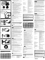
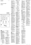
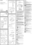
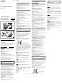
4-296-610-01(1) ATTENTION The electromagnetic fields at the specific frequencies may influence the picture of the unit. Features Color Video Camera Operating Instructions Mode d’emploi This is a bullet-shaped color video camera for which the 1/3 type EXview HAD CCD II™* has been adopted. It has the following features: ˎˎManual setting of the camera direction - panning, tilting and rotating ˎˎVari-focal auto iris lens fitted as standard. The lens focal length is 2.8 mm to 10.5 mm (SSC-CB565R/CB564R), and 9 mm to 22 mm (SSC-CB575R/CB574R). ˎˎHigh resolution and high sensitivity ˎˎAutomatic white balance tracking and adjustment (ATW/ATW-PRO) ˎˎNoise Reduction ˎˎDay/Night function allowing color/monochrome mode switching ˎˎAC 24V/DC 12V power supply system ˎˎLine Lock function (AC 24V) * EXview HAD CCD II™ is a trademark of Sony Corporation. ˎˎDo not lift the camera by only holding the cables. ˎˎIf you find condensation before use, remove the front cover and leave the camera open until the condensation has gone. Operating or storage location © 2011 Sony Corporation Printed in China Avoid operating or storing the camera in the following locations: ˎˎExtremely hot or cold places (operating temperature: –10°C to +50°C [14°F to 122°F]) ˎˎClose to heating equipment (e.g., near heaters) ˎˎClose to sources of strong magnetism ˎˎClose to sources of powerful electromagnetic radiation, such as radios or TV transmitters ˎˎLocations subject to strong vibration or shock ˎˎLocations subject to steam or high humidity ˎˎLocations subject to strong wind, such as high places ˎˎLocations where corrosive gas or flammable gas is emitted, or where salt damage may occur ˎˎLocations subject to condensation and high humidity ˎˎLocations subject to soot or oil stains Camera setting Don’t touch the PCB board by hand directly. A The following phenomena that may appear in images are specific to CCD (Charge Coupled Device) image sensors. They do not indicate malfunctions. White flecks Although the CCD image sensors are produced with high-precision technologies, fine white flecks may be generated on the screen in rare cases, caused by cosmic rays, etc. This is related to the principle of CCD image sensors and is not a malfunction. The white flecks especially tend to be seen in the following cases: when operating in a high environmental temperature when you have raised the gain (sensitivity) when using the slow shutter Vertical smear When an extremely bright object, such as a strong spotlight or flashlight, is being shot, vertical tails may be produced on the screen, or the image may be distorted. Monitor screen Vertical tails shown on the image Owner’s Record To avoid electrical shock, do not open the cabinet. Refer servicing to qualified personnel only. WARNING This installation should be made by a qualified service person and should conform to all local codes. CAUTION The rating label is located on the camera stand. Power Supply Caution for U.S.A. and Canada The SSC-CB564R/CB574R operates on 24 V AC or 12 V DC. The SSC-CB564R/CB574R automatically detects the power. In the USA, this product shall be powered by a UL listed Class 2 Power Supply Only. In Canada, this product shall be powered by a CSA Certified Class 2 Power Supply Only. Caution for other countries The SSC-CB565R/CB575R/CB564R/CB574R operates on 24 V AC or 12 V DC. The SSC-CB565R/CB575R/CB564R/CB574R automatically detects the power. Note Models SSC-CB565R and SSC-CB575R are not UL Listed. For customers in the U.S.A. (SSC-CB564R/CB574R) This device complies with Part 15 of the FCC Rules. Operation is subject to the following two conditions: (1) This device may not cause harmful interference, and (2) this device must accept any interference received, including interference that may cause undesired operation. NOTE: This equipment has been tested and found to comply with the limits for a Class A digital device, pursuant to Part 15 of the FCC Rules. These limits are designed to provide reasonable protection against harmful interference when the equipment is operated in a commercial environment. This equipment generates, uses, and can radiate radio frequency energy and, if not installed and used in accordance with the instruction manual, may cause harmful interference to radio communications. Operation of this equipment in a residential area is likely to cause harmful interference in which case the user will be required to correct the interference at his own expense. You are cautioned that any changes or modifications not expressly approved in this manual could void your authority to operate this equipment. All interface cables used to connect peripherals must be shielded in order to comply with the limits for a digital device pursuant to Subpart B of Part 15 of FCC Rules. For customers in Canada (SSC-CB564R/CB574R) Bright object (e.g., strong spotlight, strong reflected light, flashlight, the sun) Aliasing When fine patterns, stripes, or lines are shot, they may appear jagged or flicker. Location and Function of Parts Power cable BNC cable Connect the BNC cable to a monitor or video device ( I/O cable Connect the I/O cable to external control signals ( ). White: EXTERNAL CTRL OUT: H (+5 V) is output between this terminal and COM when the color mode is selected; L (0 V) is output when the B/W mode is selected. Black: COM Red: EXTERNAL CTRL IN: When H (+5 V) is applied between this terminal and COM, the color mode is selected; when L (0 V) is applied, B/W mode is selected. Notes Pour les clients au Canada (SSC-CB564R/CB574R) Cet appareil numérique de la classe A est conforme à la norme NMB-003 du Canada. Pour les clients en Europe (SSC-CB565R/CB575R) Le fabricant de ce produit est Sony Corporation, 1-7-1 Konan, Minato-ku, Tokyo, Japon. Le représentant autorisé pour EMC et la sécurité des produits est Sony Deutschland GmbH, Hedelfinger Strasse 61, 70327 Stuttgart, Allemagne. Pour toute question concernant le service ou la garantie, veuillez consulter les adresses indiquées dans les documents de service ou de garantie séparés. ATTENTION Les champs électromagnétiques aux fréquences spécifiques peuvent avoir une incidence sur l’image de cet appareil. Ce produit est une caméra vidéo cylindrique couleur pourvue d’un EXview HAD CCD II™* de type 1/3. Il présente les caractéristiques suivantes : ˎˎRéglage manuel de l’orientation de la caméra : panoramique, inclinaison et rotation ˎˎObjectif à focale variable automatique monté en standard. La longueur focale de l’objectif est comprise entre 2,8 mm et 10,5 mm (SSC-CB565R/CB564R) et 9 mm et 22 mm (SSC-CB575R/CB574R). ˎˎHaute résolution et haute sensibilité ˎˎRéglage et recherche automatiques de la balance des blancs (ATW/ATW-PRO) ˎˎRéduction du bruit ˎˎFonction Jour/Nuit permettant la commutation des modes couleur/ monochrome ˎˎSystème d’alimentation 24 V CA/12 V CC ˎˎFonction Line Lock (24 V CA) * EXview HAD CCD II™ est une marque de commerce de Sony Corporation. Remarques concernant l’utilisation Avant toute utilisation ˎˎNe soulevez pas la caméra à l’aide des câbles uniquement. ˎˎSi vous remarquez de la condensation avant d’utiliser la caméra, retirez le capot avant et laissez la caméra ouverte jusqu’à ce que toute trace de condensation ait disparu. Évitez d’utiliser ou de ranger la caméra dans les endroits suivants : ˎˎLieux extrêmement chauds ou froids (température de fonctionnement : –10°C à +50°C [14°F à 122°F]) ˎˎLieux à proximité d’un équipement de chauffage (des radiateurs, par exemple) ˎˎLieux à proximité de puissantes sources magnétiques ˎˎLieux à proximité de sources de puissantes radiations électromagnétiques, comme des transmetteurs de radio ou de télévision ˎˎLieux soumis à de fortes vibrations ou à des chocs ˎˎEndroits soumis à de la vapeur ou à une humidité élevée ˎˎEndroits soumis à un vent puissant, par exemple en hauteur ˎˎEndroits où des gaz corrosifs ou inflammables sont émis, ou où une détérioration peut être entraînée par le sel ˎˎEndroits soumis à la condensation et à des niveaux d’humidité élevés ˎˎEndroits exposés à de la suie ou des taches d’huile Paramètres de caméra Aération Pour prévenir toute surchauffe interne, n’entravez pas la circulation de l’air autour de la caméra. ˎˎMettez toujours l’appareil hors tension pour le transporter. ˎˎPour le transport de la caméra, replacez-la dans son emballage d’origine ou dans un emballage de même qualité. Nettoyage ˎˎUtilisez une soufflante pour dépoussiérer le couvercle de l’objectif. ˎˎUtilisez un chiffon doux et sec pour nettoyer les surfaces externes de la caméra. Pour éliminer les taches tenaces, utilisez un chiffon doux légèrement imprégné d’une solution détergente, puis essuyez la caméra. ˎˎN’utilisez pas de solvants puissants tels que de l’alcool, du benzène ou des diluants car vous risquez d’endommager le fini des surfaces de l’appareil. Remarque concernant les faisceaux laser Les faisceaux laser risquent d’endommager les capteurs d’images. Il est fortement déconseillé d’exposer la surface d’un capteur d’images aux radiations d’un faisceau laser dans un environnement où un faisceau laser est utilisé. Phénomène typique des CCD Les phénomènes suivants qui peuvent apparaître dans les images sont particuliers aux capteurs d’images CCD (Charge Coupled Device). Ils ne signalent pas une anomalie. Fall-prevention rope mounting screw hole Taches blanches When installing the camera on the ceiling or the wall, secure the supplied fall-prevention rope to this hole using the supplied screw. Camera stand Caution Take care not to trap the cables between the camera and the ceiling or the wall. If the cables are trapped, they may break and cause fire or electric shock. Rating label This label shows the device name and electrical rating. Bien que les capteurs CCD soient fabriqués à l’aide de technologies de haute précision, il arrive rarement que des petites taches blanches apparaissent sur l’écran; celles-ci sont causées par les rayons cosmiques, etc. Cet effet est dû à la technologie des capteurs d’images CCD et ne signale pas une anomalie. Les taches blanches sont surtout visibles dans les cas suivants : Lors du fonctionnement à haute température ambiante Lorsque vous avez augmenté le gain (la sensibilité) Lors de l’utilisation de l’obturateur lent Bande verticale Outside Camera angle fixing screw First loosen the screw with the supplied wrench and face the camera head in the desired direction, then tighten the screw to secure it. Lorsqu’un objet très lumineux est filmé, comme un projecteur ou un flash, il arrive que des bandes verticales apparaissent sur l’écran, ou que l’image soit déformée. Écran du moniteur Traînées verticales sur l’image Sun shield fixing screw Sun shield The sun shield can be adjusted longitudinally up to 20mm, as required. Objet brillant (éclairage directionnel intense, lumière réfléchie intense, flashs, soleil, etc.) Distorsion (continued on the reverse side) Câble BNC ). Remarque L’image de sortie est principalement utilisée pour régler l’angle de vue et risque de ne pas s’afficher correctement, selon le format vidéo et les paramètres de la taille d’image. ˎˎL’image risque de ne pas s’afficher correctement sur le plan horizontal et/ou vertical. ˎˎIl se peut que l’image soit réduite. Câble E/S Raccordez le câble E/S aux bornes des signaux de commande externe ( ). Blanc : EXTERNAL CTRL OUT : H (+ 5 V) est appliqué entre cette borne et COM lorsque le mode couleur est sélectionné ; L (0 V) est appliqué lorsque le mode B/W est sélectionné. Noir : COM Rouge : EXTERNAL CTRL IN : lorsque H (+ 5 V) est appliqué entre cette borne et COM, le mode couleur est sélectionné ; lorsque L (0 V) est appliqué, le mode B/W est sélectionné. Remarques ˎˎPour la connexion des signaux de commande externes, réglez le commutateur D/N sur OFF. ˎˎIsolez les trois extrémités du câble E/S afin d’éviter un court-circuit lorsque celui-ci n’est pas utilisé. Trou de vis de montage du câble anti-chute Lors de l’installation de la caméra au plafond ou sur le mur, fixez le câble anti-chute fourni à ce trou à l’aide de la vis fournie. Support de la caméra Précaution Veillez à ne pas coincer les câbles entre la caméra et le plafond ou le mur. Si les câbles sont coincés, leur rupture peut causer un incendie ou un choc électrique. Étiquette de classification Cette étiquette indique le nom de l’appareil et sa classification électrique. Extérieur Vis de fixation de l’angle de la caméra Desserrez tout d’abord la vis à l’aide de la clé fournie et placez le bloc de caméra face à la direction souhaitée, puis resserrez la vis pour assurer la fixation. Vis de fixation du pare-soleil Pare-soleil Le pare-soleil peut être réglé jusqu’à 20 mm dans le sens longitudinal, selon vos besoins. Caractéristiques ˎˎFor external control signal connection, set the D/N switch to OFF. ˎˎInsulate the three wire ends of the I/O cable to avoid a short circuit when not in use. Camera This is a Class A product. In a domestic environment, this product may cause radio interference in which case the user may be required to take adequate measures. In the case that interference should occur, consult your nearest authorized Sony service facility. This apparatus shall not be used in the residential area. Les modèles SSC-CB565R et SSC-CB575R ne sont pas homologués UL. Transport ). Note The output image is mainly used to adjust the view angle, and may not be displayed correctly, depending on the video format and image size settings. ˎˎThe image may not be displayed properly in the horizontal and/or vertical plane. ˎˎThe image size may be reduced. For the customers in Europe (SSC-CB565R/CB575R) WARNING Remarque Ne touchez pas la carte électronique directement avec la main. Connect the power cable to AC 24 V or DC 12 V ( ). The connector tip is a quick-disconnect type. The cable can be lengthened by attaching an extension cable to the connector tip at the end of the cable. Front cover For the customers in Europe, Australia and New Zealand (SSC-CB565R/CB575R) Back This Class A digital apparatus complies with Canadian ICES-003. The manufacturer of this product is Sony Corporation, 1-7-1 Konan, Minato-ku, Tokyo, Japan. The Authorized Representative for EMC and product safety is Sony Deutschland GmbH, Hedelfinger Strasse 61, 70327 Stuttgart, Germany. For any service or guarantee matters please refer to the addresses given in separate service or guarantee documents. L’unité SSC-CB565R/CB575R/CB564R/CB574R fonctionne sur du 24 V CA ou du 12 V CC. L’unité SSC-CB565R/CB575R/CB564R/CB574R détecte automatiquement l’alimentation. Lieu d’utilisation ou de rangement Before operating the unit, please read this manual thoroughly and retain it for future reference. WARNING Avertissement pour les autres pays Il s’agit d’un produit de Classe A. Dans un environnement domestique, cet appareil peut provoquer des interférences radio, dans ce cas l’utilisateur peut être amené à prendre des mesures appropriées. Si des interférences se produisent, contactez votre service après-vente agréé Sony. Ne pas utiliser cet appareil dans une zone résidentielle. Typical CCD phenomenon Serial No. Avertissement pour les États-Unis et le Canada AVERTISSEMENT Laser beams may damage image sensors. You are cautioned that the surface of image sensors should not be exposed to laser beam radiation in an environment where a laser beam device is used. Model No. Alimentation Transportation Note on laser beams The model and serial numbers are located on the camera stand. Record these numbers in the spaces provided below. Refer to these numbers whenever you call upon your Sony dealer regarding this product. La plaquette des caractéristiques nominales se trouve sur le support de la caméra. To prevent heat buildup, do not block air circulation around the camera. ˎˎUse a blower to remove dust from the lens cover. ˎˎUse a soft, dry cloth to clean the external surfaces of the camera. Stubborn stains can be removed using a soft cloth dampened with a small quantity of detergent solution. Then wipe the camera dry. ˎˎDo not use volatile solvents such as alcohol, benzene or thinners as they may damage the surface finishes. English ATTENTION Ventilation Cleaning Branchez le câble sur une alimentation 24 V CA ou 12 V CC ( ). L’extrémité du connecteur est un embout à déconnexion rapide. Vous pouvez allonger le câble en attachant un câble de rallonge à l’extrémité du connecteur située au bout du câble. Raccordez le câble BNC à un moniteur ou un périphérique vidéo ( Pour les clients en Europe, Australie et Nouvelle-Zélande (SSC-CB565R/CB575R) ˎˎAlways turn off the power when carrying. ˎˎWhen transporting the camera, repack it as originally packed at the factory or in materials of equal quality. B Afin d’écarter tout risque d’électrocution, garder le coffret fermé. Ne confier l’entretien du produit qu’à un personnel qualifié. Utilisez une alimentation classe 2 répertoriée UL (aux États-Unis) ou homologuée CSA (au Canada). Before Use Arrière Câble d’alimentation AVERTISSEMENT La SSC-CB564R/CB574R fonctionne sur du 24 V CA ou 12 V CC. La SSC-CB564R/CB574R détecte automatiquement l’alimentation. Notes on Use SSC-CB565R/CB575R SSC-CB564R/CB574R Emplacement et fonction des pièces Français Avant d’utiliser cet appareil, lisez attentivement le présent mode d’emploi et conservez-le pour toute référence ultérieure. Lorsque des lignes ou des motifs précis sont filmés, il arrive qu’ils soient déformés ou qu’ils clignotent. Capot avant Caméra (suite au verso) 1: SYNC (Sync Lock) switch (Initial setting: INT) Use this switch to set the camera synchronization mode to INT (Internal) or LL (Line Lock). When the camera power is DC 12 V, the camera is in the internal operation mode regardless of the switch setting. C Note If the Line Lock function is used while camera power is unstable, the camera image may flutter. Minimum object distance Signal system 2: 3: SSC-CB575R/CB574R AGC (Automatic Gain Control) switch (Initial setting: ON) Use this switch to increase the gain of the video amplifier when set to ON. iBLC (Intelligent Backlight Compensation) switch (Initial setting: OFF) Use this switch to adjust the exposure to compensate for situations where the subject is lit from behind. 4: ATR-Lite (Adaptive Tone Reproduction) switch (Initial setting: OFF) When the switch is set to ON, the camera will adjust the tone automatically according to ambient brightness and darkness. 5: SHARPNESS switch (Initial setting: NORMAL) When the switch is set to ON, the camera will produce sharper images. 6: WB (White Balance) switch (Initial setting: ATW) Choose the WB mode of the camera: ATW PRO (when the switch is set to ON): the camera will adjust the WB automatically, based on the color temperature of fluorescent, incandescent or natural light. ATW (when the switch is set to OFF): the camera will adjust the WB automatically, especially under certain lights, such as sodium, etc. 7: D/N (Day/Night) switch (Initial setting: AUTO) Choose the D/N mode of the camera: D/N mode (when the switch is set to ON): switches to the color mode when in a brightly lit environment; switches to the monochrome mode when in a low light environment. Color mode (when the switch is set to OFF) 8: D/N_TIME (Day/Night time) switch (Initial setting: LONG) Sets the time for switching Day/Night mode. SHORT takes more than 2 seconds, and LONG takes more than 30 seconds. 9: AdIR (Advanced IR control) switch (Initial setting: ON) When the switch is set to ON, the camera will compensate for overexposure in Night mode. 10:IRIS (Lens iris control) switch (Initial setting: AUTO) When the switch is set to ON, the aperture is completely open, which allows for easier focusing. SSC-CB565R/CB564R D Vertical mark/ Repère vertical Hole for connecting cables ø30 (1 3/16)/ Trou pour câbles de connexion ø30 (1 3/16) Hole for installing the stand/Trou servant à l’installation du support Horizontal mark/ Repère horizontal 83.5 (3 3/8) TEMPLATE Note Set this switch to OFF when using the camera in the normal way; otherwise, the camera image may flutter. MONITOR output jack 83.5 (3 /8) 3 Unit: mm (inches)/Unité : mm (pouces) E Connect this jack to a video input connector of a video monitor. You can adjust the camera or lens while looking at the image on the video monitor. After adjusting the camera or lens, disconnect the cable. Close the cover firmly to keep the camera waterproof. PHASE adjustment screw Use this screw to adjust the vertical phase in Line Lock mode. Lens Focus lever Wall/Mur Loosen the lever, and move it to adjust the focal length. Tighten the lever to secure its position. Zoom lever Loosen the lever, and move it to adjust the angle of view. Tighten the lever to secure its position. Connecting the Cables 1 Connect the BNC cable to a monitor or video device (see figure ). 2 Connect the I/O cable to external control signals (see figure ). 3 Connect the power cable to the power supply (AC 24 V/DC 12 V) (see figure Fall-prevention rope (supplied)/ Câble anti-chute (fourni) ). Caution When you have connected the power cable, be sure that the exposed ends of the power cable do not touch each other to prevent a short circuit. F Installation –1 1,3 4,11 WARNING ˎˎIf you attach the camera at a height, such as the wall or the ceiling, etc., entrust the installation to an experienced contractor or installer. ˎˎIf you install the camera at a height, ensure that the installation location and its material are strong enough to withstand a weight of 15 kg (33 lb 1 oz) or more, and then install the camera securely. If they are not strong enough, the camera may fall and cause serious injury. ˎˎTo prevent the camera from falling, make sure to attach the supplied fall-prevention rope. ˎˎIf you attach the camera to a high location, check periodically, at least once a year, to ensure that the connection has not loosened. If conditions warrant, make this periodic check more frequently. 2,10 Deciding the Installation Location of the Camera 5,9 After deciding the direction in which the camera will shoot, make the required hole (ø30 mm (1 3/16 inches)) for connecting cables using the supplied template. Then decide the four mounting hole positions to install the camera stand. To prevent from rainwater flowing into the camera through the hole for connecting cables, installing the camera on the wall is recommended. –2 8 Mounting screws The camera stand is provided with four ø5 mm (7/32 inch) mounting holes. Install the camera stand on a wall or ceiling with screws through four mounting holes. The required mounting screws differ depending on the installation location and its material. (Mounting screws are not supplied.) Steel wall or ceiling: Use M4 bolts and nuts. Wooden wall or ceiling: Use M4 tapping screws. The panel thickness must be 15 mm (5/8 inch) or more. Concrete wall: Use anchors, bolts and plugs suitable for concrete walls. Junction box: Use screws to match the holes on the junction box. 6,7 WARNING The required mounting screws differ depending on the installation location and its material. If you do not secure the camera with the appropriate mounting screws, the camera may fall off. G Side/Côté Installing the Camera 1 Pass all the cables through the hole for connecting cables made at the installing surface. 2 Fix the supplied fall-prevention rope to the camera unit and the wall or ø100 (4) ceiling. Fix the rope with the supplied Screw M4 × 8 to the hole for the rope on the camera stand. Fix the rope to the wall or ceiling. 3 Install the camera on the wall or ceiling. Insert the four screws in the screw holes on the camera stand, and then tighten the screws to attach the camera. When installing the camera on the wall, be sure the TOP mark on the camera stand is at the top. Refer to “Mounting screws” for screw to be used. 110 (4 3/8) 189 (7 1/2) 206.7 (8 1/2) Bottom/Bas Adjusting the Camera Direction and Coverage 1 Loosen the camera angle fixing screw with the supplied wrench. 2 Adjust the camera to turn the lens in the desired direction. 3 Tighten the camera angle fixing screw with the supplied wrench to fix the ø7 7( 3 1 /8) Unit: mm (inches)/Unité : mm (pouces) English Inside Mode setting DIP switch The following DIP switches are turned on if they have been set to the top positions. Pin No. Switch 1 2 3 4 5 6 7 8 9 10 SYNC AGC iBLC ATR-Lite SHARPNESS WB D/N D/N_TIME AdIR IRIS Location Up (ON) LL ON ON ON SHARP ATW PRO AUTO SHORT ON OPEN Down (OFF) INT OFF OFF OFF NORMAL ATW OFF LONG OFF AUTO camera. 4 Loosen the sun shield fixing screw, and take off the sun shield. 5 Remove the front cover by rotating anticlockwise. 6 Loosen the zoom lever and move it to the right or left to adjust the angle of view. When you have set the zoom lever to the desired position, tighten it to fix the angle of view. 7 Loosen the focus lever and move it to the right or left to adjust the focal length. When you have set the focus lever to the desired position, tighten it to fix the focal length. 8 Use the PHASE adjustment screw to adjust the vertical phase of cameras synchronized by LL. 9 Install the front cover tightly by rotating clockwise. 10 Slide in the sun shield along the two projected lines on the camera. 11 Tighten the screw to fix the sun shield. 12 Repeat step 1 to 11 until the coverage and focus are determined. Notes ˎˎIf you adjust the camera angle without loosening the camera angle fixing screw, internal damage may occur. ˎˎIf the camera head is too heavy to be adjusted, loosen the camera angle fixing screw until it moves freely. Specifications Image device Effective picture elements Focal length Maximum relative aperture View angle Synchronization system Horizontal resolution Minimum illumination Video output Video S/N White balance Automatic gain control (AGC) Monitor out IR working distance IR Led Power supply Power consumption Operating temperature Storage temperature Operating humidity Storage humidity Dimensions (camera body) Mass Supplied accessories SSC-CB565R/CB564R: Horizontal: 101.8° (wide) - 27.4° (tele) Vertical: 73.7° (wide) - 20.6° (tele) SSC-CB575R/CB574R: Horizontal: 32.1° (wide) - 13.1° (tele) Vertical: 23.3° (wide) - 9.8° (tele) SSC-CB565R/CB564R: 0.3 m SSC-CB575R/CB574R: 1 m SSC-CB565R/CB575R: PAL color system SSC-CB564R/CB574R: NTSC color system Internal/Line lock switchable 650 TV lines (normal mode) SSC-CB565R/CB564R: Color: 0.06 lx at F1.2 (50 IRE, AGC ON) B/W: 0 lx at F1.2 (50 IRE, AGC ON, IR ON) SSC-CB575R/CB574R: Color: 0.09 lx at F1.4 (50 IRE, AGC ON) B/W: 0 lx at F1.4 (50 IRE, AGC ON, IR ON) 1.0 Vp-p, 75 Ω, negative sync , BNC cabel 55 dB (AGC OFF, WEIGHT ON) ATW-PRO/ATW ON/OFF RCA jack 30 m (50 IRE) 14 pcs SSC-CB565R/CB575R: AC 24V (50 Hz)/DC 12 V SSC-CB564R/CB574R: AC 24V (60 Hz)/DC 12 V 5.5 W –10°C to +50°C (14°F to 122°F) –40°C to +60°C (–40°F to +140°F) 20% to 80% 20% to 95% ø77 mm × 110 mm (ø3 1/8 inches × 4 3/8 inches) (not including projecting parts) Approx. 650 g (1 lb 7.0 oz) Template (1), Fall-prevention rope (1), Screw M4 × 8 (1), Wrench (1), Installation Manual (this document) (1 set) Note Always verify that the unit is operating properly before use. SONY WILL NOT BE LIABLE FOR DAMAGES OF ANY KIND INCLUDING, BUT NOT LIMITED TO, COMPENSATION OR REIMBURSEMENT ON ACCOUNT OF THE LOSS OF PRESENT OR PROSPECTIVE PROFITS DUE TO FAILURE OF THIS UNIT, EITHER DURING THE WARRANTY PERIOD OR AFTER EXPIRATION OF THE WARRANTY, OR FOR ANY OTHER REASON WHATSOEVER. Recommendation of Periodic Inspections In case using this device over an extended period of time, please have it inspected periodically for safe use. It may appear flawless, but the components may have deteriorated over time, which may cause a malfunction or accident. For details, please consult the store of purchase or an authorized Sony dealer. Français Intérieur Commutateur DIP de réglage de mode Les commutateurs DIP suivants sont activés s’ils ont été réglés sur les positions supérieures. Commutateur 1 2 3 4 5 6 7 8 9 10 SYNC AGC iBLC ATR-Lite SHARPNESS WB D/N D/N_TIME AdIR IRIS Emplacement Haut (ON) LL ON ON ON SHARP ATW PRO AUTO SHORT ON OPEN Bas (OFF) INT OFF OFF OFF NORMAL ATW OFF LONG OFF AUTO 1 : Commutateur SYNC (Verrouillage de synchronisation) (réglage initial : INT) Ce commutateur permet de régler la synchronisation de la caméra sur le mode INT (Interne) ou LL (Verrouillage de ligne). Lorsque l’alimentation de la caméra est de 12 V CC, la caméra est en mode de fonctionnement interne, quelle que soit la position du commutateur. Remarque Si la fonction Line Lock (Verrouillage de ligne) est utilisée quand l’alimentation de la caméra est instable, l’image de la caméra risque de trembler. 2 : Commutateur AGC (Contrôle de gain automatique) (réglage initial : ON) Utilisez ce commutateur pour augmenter le gain de l’amplificateur vidéo lorsqu’il est réglé sur ON. 3 : Commutateur iBLC (Correction intelligente du rétroéclairage) (réglage initial : OFF) Utilisez ce commutateur pour régler l’exposition et compenser les situations où le sujet est éclairé par derrière. 4 : Commutateur ATR-Lite (Reproduction de tonalité adaptative) (réglage initial : OFF) Lorsque ce commutateur est réglé sur ON, la caméra ajuste automatiquement la tonalité en fonction des différences entre les tons lumineux et sombres. 5: Commutateur SHARPNESS (réglage initial : NORMAL) Lorsque le commutateur est réglé sur ON, la caméra produit des images plus nettes. 6 : Commutateur WB (Balance des blancs) (réglage initial : ATW) Sélectionnez le mode WB de la caméra : ATW PRO (lorsque le commutateur est sur ON) : règle automatiquement la balance des blancs en se basant sur la température de couleur d’un éclairage fluorescent, d’une lampe à incandescence ou de la lumière naturelle. ATW (lorsque le commutateur est sur OFF) : la caméra règle automatiquement la balance des blancs, en particulier sous certains éclairages, tels qu’une lampe au sodium. 7 : Commutateur D/N (Jour/Nuit) (réglage initial : AUTO) Sélectionnez le mode D/N de la caméra : Mode D/N (lorsque le commutateur est réglé sur ON) : bascule en mode couleur dans un environnement très lumineux ; bascule en mode monochrome dans un environnement faiblement lumineux. Mode couleur (lorsque le commutateur est sur OFF) 8 : Commutateur D/N_TIME (Durée jour/nuit) (réglage initial : LONG) Règle la durée de commutation du mode Diurne/Nocturne. SHORT dure plus de 2 secondes et LONG plus de 30 secondes. 9: Commutateur AdIR (contrôle IR avancé) (réglage initial : ON) Lorsque le commutateur est réglé sur ON, la caméra compense la surexposition en mode Nuit. 10:Commutateur IRIS (commande du diaphragme de l’objectif) (réglage initial : AUTO) Lorsque le commutateur est réglé sur ON, l’ouverture est totale, ce qui permet une mise au point plus facile. Remarque Réglez ce commutateur sur OFF lorsque vous utilisez la caméra normalement ; dans le cas contraire, l’image de la caméra risque de trembler. Jack de sortie MONITOR Branchez ce jack sur un connecteur d’entrée vidéo d’un moniteur vidéo. Vous pouvez régler la caméra ou l’objectif tout en regardant l’image sur le moniteur vidéo. Déconnectez le câble après avoir réglé la caméra ou l’objectif. Fermez bien le couvercle pour maintenir l’étanchéité de la caméra. Choix de l’emplacement d’installation de la caméra Utilisez cette vis pour régler la phase verticale en mode Line Lock (Verrouillage de ligne). Objectif Levier de mise au point Desserrez le levier et tournez-le pour régler la longueur focale. Serrez le levier pour verrouiller sa position. Levier du zoom Desserrez le levier et tournez-le pour régler l’angle de vue. Serrez le levier pour verrouiller sa position. Connexion des câbles 1 Connectez le câble BNC à un moniteur ou un périphérique vidéo. (Voir l’illustration .) l’illustration ). l’illustration .) Après avoir choisi la direction dans laquelle la caméra va filmer, percez le trou requis (ø30 mm (1 3/16 pouces)) pour raccorder les câbles à l’aide du modèle fourni. Puis choisissez les quatre positions pour les trous qui serviront à installer le support de la caméra. Pour éviter que de l’eau de pluie ne s’infiltre dans la caméra par le trou des câbles de connexion, il est conseillé d’installer la caméra sur un mur. Vis de montage Le support de la caméra est fourni avec quatre trous de montage de 5 mm (7/32 pouce) de diamètre. Installez le support de la caméra au plafond ou sur un mur à l’aide des vis insérées dans les quatre orifices de fixation. Les vis de montage requises seront différentes en fonction du lieu d’installation et des matériaux (vis de montage non fournies.) Paroi ou plafond en acier : utilisez des écrous et des boulons M4. Paroi ou plafond en bois : utilisez des vis autotaraudeuses M4. L’épaisseur du panneau doit être d’au moins 15 mm (5/8 pouce). Mur en béton : utilisez des ancrages, des boulons et des chevilles pour murs en béton. Boîte de jonction : utilisez des vis s’adaptant aux trous de la boîte de jonction. 3 Connectez le câble d’alimentation à l’alimentation (24 V CA/12 V CC). (Voir Attention Lorsque vous raccordez le câble d’alimentation, veillez à ce que ses extrémités ne se touchent pas, afin d’éviter un court-circuit. Installation de la caméra 1 Faites passer tous les câbles par le trou réservé au raccordement des câbles au niveau de la surface d’installation. 2 Fixez le câble anti-chute fourni à la caméra et au plafond ou sur le mur. Fixez le câble à l’aide de la vis M4 × 8 fournie au trou réservé à cet effet sur le support de la caméra. Fixez le câble au plafond ou sur le mur. 3 Installez la caméra au plafond ou sur le mur. Insérez les quatre vis dans les trous de vis situés sur le support de la caméra, puis serrez-les pour fixer la caméra. Lorsque vous installez la caméra sur un mur, vérifiez que le repère TOP sur le support de la caméra est dirigé vers le haut. Reportez-vous à la section « Vis de montage » pour savoir quelle vis utiliser. Réglage de la direction et de la zone couverte par la caméra 1 Desserrez la vis de fixation de l’angle de la caméra à l’aide de la clé fournie. 2 Réglez la caméra pour orienter l’objectif dans la direction souhaitée. 3 Serrez la vis de fixation de l’angle de la caméra à l’aide de la clé fournie afin de fixer la caméra. 4 Desserrez la vis de fixation du pare-soleil et enlevez le pare-soleil. 5 Retirez le capot avant en le faisant tourner dans le sens inverse des aiguilles d’une montre. 6 Desserrez le levier de zoom et tournez-le vers la droite ou vers la gauche pour régler l’angle de vue. Une fois le levier du zoom réglé sur la position souhaitée, pour fixer l’angle de vue, serrez la vis. 7 Desserrez le levier de zoom et tournez-le vers la droite ou vers la gauche pour régler la longueur focale. Une fois le levier de mise au point réglé sur la position souhaitée, pour fixer la longueur focale, serrez la vis. 8 Utilisez la vis de réglage de la PHASE pour régler la phase verticale des caméras synchronisées avec LL. 9 Fixez solidement le capot avant en le faisant tourner dans le sens des aiguilles d’une montre. 10 Faites glisser le pare-soleil le long des deux lignes projetées sur la caméra. 11 Serrez la vis pour fixer le pare-soleil. 12 Répétez les étapes 1 à 11 jusqu’à ce que le champ et la mise au point soient déterminés. Remarques ˎˎSi vous réglez l’angle de la caméra sans desserrer la vis de montage de l’angle de la caméra, vous risquez d’entraîner des dommages internes. ˎˎSi le poids du bloc de caméra empêche le réglage, desserrez la vis de fixation de l’angle de la caméra jusqu’à ce qu’il bouge sans entrave. Spécifications Imageur Pixels effectifs Longueur focale Ouverture relative maximale Angle de vue Distance objet minimale Signal Système de synchronisation Résolution horizontale Lumière minimale Sortie vidéo Rapport vidéo signal sur bruit Balance des blancs Contrôle de gain automatique (AGC) Sortie moniteur Distance de travail IR DEL IR Alimentation Consommation électrique Température de service Température de stockage Humidité de service Humidité de stockage Dimensions (boîtier de la caméra) Masse Accessoires fournis Vis de réglage de la PHASE 2 Raccordez le câble E/S aux bornes des signaux de commande externe. (Voir Interline transfer 1/3 type SSC-CB565R/CB575R: 976 (H) 582 (V) SSC-CB564R/CB574R: 976 (H) 494 (V) SSC-CB565R/CB564R: 2.8 mm - 10.5 mm SSC-CB575R/CB574R: 9 mm - 22 mm SSC-CB565R/CB564R: F1.2 SSC-CB575R/CB574R: F1.4 AVERTISSEMENT ˎˎSi vous fixez la caméra en hauteur (sur un mur ou au plafond, par exemple), confiez l’installation à un entrepreneur ou à un installateur qualifié. ˎˎSi vous installez la caméra en hauteur, assurez-vous que l’emplacement d’installation et son matériel sont assez résistants pour pouvoir soutenir un poids de 15 kg (33 lb 1 oz) ou plus, puis installez solidement la caméra. S’ils ne sont pas assez solides, la caméra risque de tomber et de causer de graves blessures. ˎˎPour éviter que la caméra ne tombe, veillez à attacher le câble anti-chute fourni. ˎˎSi vous fixez la caméra en hauteur, vérifiez périodiquement (au moins une fois par an) que la connexion est toujours correcte. Si les conditions l’exigent, augmentez la fréquence des vérifications. AVERTISSEMENT Les vis de montage requises seront différentes en fonction du lieu d’installation et des matériaux. Si vous ne fixez pas solidement la caméra avec les vis de montage appropriées, la caméra risque de tomber. Design and specifications are subject to change without notice. N° de broche Installation Transfert interligne type 1/3 SSC-CB565R/CB575R : 976 (H) × 582 (V) SSC-CB564R/CB574R : 976 (H) × 494 (V) SSC-CB565R/CB564R : 2,8 mm - 10,5 mm SSC-CB575R/CB574R : 9 mm - 22 mm SSC-CB565R/CB564R : F1,2 SSC-CB575R/CB574R : F1,4 SSC-CB565R/CB564R : Horizontal : 101,8° (grand) - 27,4° (télé) Vertical : 73,7° (grand) - 20,6° (télé) SSC-CB575R/CB574R : Horizontal : 32,1° (grand) - 13,1° (télé) Vertical : 23,3° (grand) - 9,8° (télé) SSC-CB565R/CB564R : 0,3 m SSC-CB575R/CB574R : 1 m SSC-CB565R/CB575R : Système de couleurs PAL SSC-CB564R/CB574R : Système de couleurs NTSC Interne/Verrouillage de ligne commutable 650 lignes TV (mode normal) SSC-CB565R/CB564R : Couleur : 0,06 lx à F1,2 (50 IRE, AGC ON) Noir et blanc : 0 lx à F1,2 (50 IRE, AGC ON, IR ON) SSC-CB575R/CB574R : Couleur : 0,09 lx à F1,4 (50 IRE, AGC ON) Noir et blanc : 0 lx à F1,4 (50 IRE, AGC ON, IR ON) 1,0 Vc-c, 75 Ω, sync. négative, câble BNC 55 dB (AGC OFF, WEIGHT ON) ATW-PRO/ATW ON/OFF Prise RCA 30 m (50 IRE) 14 pièces SSC-CB565R/CB575R : 24 V AC (50 Hz)/12 V CC SSC-CB564R/CB574R : 24 V AC (60 Hz)/12 V CC 5,5 W – 10°C à + 50°C (14°F à + 122°F) – 40°C à + 60°C (– 40°F à + 140°F) 20% à 80% 20% à 95% ø77 mm × 110 mm (ø3 1/8 pouces × 4 3/8 pouces) (pièces saillantes non comprises) Environ 650 g (1 lb 7,0 oz) Modèle (1), Câble anti-chute (1), Vis M4 × 8 (1), clé (1), Manuel d’installation (le présent document) (1 exemplaire) La conception et les spécifications sont sujettes à modifications sans préavis. Remarque Vérifiez toujours que l’appareil fonctionne correctement avant l’utilisation. SONY N’ASSUMERA PAS DE RESPONSABILITÉ POUR LES DOMMAGES DE QUELQUE SORTE QU’ILS SOIENT, INCLUANT MAIS NE SE LIMITANT PAS À LA COMPENSATION OU AU REMBOURSEMENT, À CAUSE DE LA PERTE DE PROFITS ACTUELS OU FUTURS SUITE À LA DÉFAILLANCE DE CET APPAREIL, QUE CE SOIT PENDANT LA PÉRIODE DE GARANTIE OU APRÈS SON EXPIRATION, OU POUR TOUTE AUTRE RAISON QUELLE QU’ELLE SOIT. Recommandations pour les inspections périodiques En cas d’utilisation de cet appareil pendant une période prolongée, veillez à son entretien périodique pour la sécurité. Il peut sembler sans défaut, mais il est possible que les composants se soient détériorés avec le temps, ce qui peut provoquer un dysfonctionnement ou un accident. Pour plus d’informations, consultez le magasin où vous avez acheté l’appareil ou un revendeur Sony agréé. For Customer in China 根据中华人民共和国信息产业部第39号令《电子信息产品 污染控制管理办法》及标准中要求的“有毒有害物质或元 素名称及含量”等信息,本产品相关信息请参考以下链 接:http://pro.sony.com.cn