1
MODEL: TS44 , TS45
AC: 115VAC 2,3A / 230VAC 1,2A /
240VAC 1,1A
50-60Hz
DC: 1,0A
6V or 12V x8
INSTRUCTIONS FOR USE
IMPORTANT: Read completely
before charging
MODE D’EMPLOI
IMPORTANT: à lire avant
d’utiliser l’appareil
MODO DE EMPLEO
IMPORTANTE: a leer antes de
utilizar el aparato
ANWENDUNGSVORSCHRIFTEN
WICHTIG: Vollständig vor der
Benutzung lesen
GEBRUIKSAANWIJZING
BELANGRIJK: Lees volledig voor
gebruik
ISTRUZIONI PER L’USO
IMPORTANTE: da leggere prima
di utilizzare l’apparecchio
SAE connectors
+
- 8x 6V or 12V
AGM-MF - 3Ah min.
STD / GEL - 4Ah min.
Automatic charger for 6 and 12V lead/acid batteries • Chargeur automatique
pour batteries 6 et 12V plomb-acide • Cargador automático para baterías
6 y 12V plomo-ácido • Automatische Ladegerät für 6 und 12V Blei-Säure
Batterien • Automatische lader voor 6 en 12V loodzuur accu’s • Caricabatterie
automatico per batterie 6 e 12V piombo-acido
MOUNTING NOTICE
NOTICE DE MONTAGE
NOTA PARA EL MONTAJE
WANDMONTIERUNG
MUURBEVESTIGING
NOTA DI MONTAGGIO
THIS PORTION OF THE MANUAL CONTAINS IMPORTANT SAFETY INSTRUCTIONS FOR
THE OPTIMATE PRO-8 BATTERY CHARGER. IT IS OF THE UTMOST IMPORTANCE THAT
EACH TIME, BEFORE USING THE CHARGER, YOU READ AND EXACTLY FOLLOW THESE
INSTRUCTIONS. SAVE THESE INSTRUCTIONS.
AUTOMATIC CHARGER FOR 12V LEAD-ACID BATTERIES
DO NOT USE FOR NiCd, NiMH, Li-Ion OR NON-RECHARGEABLE BATTERIES.
1. CAUTION : CLASS II APPLIANCE. DO NOT CONNECT TO GROUND.
2. For indoor use only. Do not expose charger to rain or snow.
3. Use of an attachment not recommended or sold by the battery charger manufacturer may result in a risk of fire, electric shock,or injury to
persons.
4. To reduce risk of damage to electric plug and cord,pull by plug rather than cord when disconnecting charger.
5. An extension cord should not be used unless absolutely necessary. Use of improper extension cord could result in a risk of fire and
electric shock.If extension cord must be used make sure that :
a) pins on plug of extension cord are the same number, size and shape as those of plug on charger.
b) the extension cord is property wired and in good electrical condition,and
c) the conductor wire size is large enough for the AC ampere rating of the charger as specified in the table below.
AC INPUT RATING IN AMPERES
Equal to or greater than
But less than
2A
3A
LENGTH OF CORD,
FEET (m)
AWG SIZE
OF CORD
25 (17.6)
50 (15.2)
100 (30.5)
18
18
14
6. Do not operate charger with damaged cord or plug - replace the cord or plug immediately.
7. Do not operate charger if it has received a sharp blow, been dropped,or otherwise damaged in any way; take it to a qualified serviceman.
8. Do not disassemble charger; take it to a qualified serviceman when service or repair is required.
Incorrect reassembly may result in a risk of electric shock or fire.
9. To reduce risk of electric shock, unplug the charger from outlet before attempting any maintenance or cleaning.
Turning off controls will not reduce this risk.Clean only with slightly moist,not wet, cloth.Do not use solvents.
10. WARNING - RISK OF EXPLOSIVE GASES.
a) WORKING IN VICINITY OF A LEAD-ACID BATTERY IS DANGEROUS. B ATTERIES GENERATE EXPLOSIVE GASES DURING NORMAL BATTERY
OPERATION. FOR THIS REASON, IT IS OF UTMOST IMPORTANCE THAT YOU FOLLOW THE INSTRUCTIONS EACH TIME YOU USE THE CHARGER.
b) To reduce risk of battery explosion,follow these instructions and those published by the battery manufacturer
and manufacturer of any equipment you intend to use in vicinity of the battery. Review cautionary marking on these products and on engine.
11. PERSONAL PRECAUTIONS.
a) Someone should be within range of your voice OR close enough to come to your aid when you work near a lead-acid battery.
b) Have plenty of fresh water and soap nearby in case battery acid contacts skin, clothing or eyes.
c) Wear complete eye protection and clothing protection. Avoid touching eyes while working near battery.
d) If battery acid contacts or enters eye, flood eye with cold running water for at least 10 minutes and get medical attention
immediately. If battery acid contacts skin or clothing, wash immediately with soap & water. If acid enters an eye , immediately
flood eye with running cold water for at least 10 minutes & get medical attention immediately.
e) NEVER smoke or allow a spark or flame in vicinity of battery or engine.
f) Be extra cautious to reduce risk of dropping a metal tool onto battery. It might spark or short-circuit battery or other electrical
part that may cause explosion.
g) Remove personal metal items such as rings, bracelets ,necklaces , and watches when working with a lead-acid
battery. A lead-acid battery can produce a short-circuit current high enough to weld a ring or the like to metal, causing a severe
burn.
i) NEVER charge a frozen battery.
3
SAFETY US & CAN
IMPORTANT SAFETY INSTRUCTIONS FOR CANADA & USA
12. PREPARING TO CHARGE
SAFETY US & CAN
a) If necessary to remove battery from vehicle to charge,always remove grounded terminal from battery first.
Make sure all accessories in the vehicle are off, so as not to cause an arc.
b) Be sure area around battery is well ventilated while battery is being charged. Gas can be forcefully blown away
by using a piece of cardboard or other non-metallic material as a fan.
c) Clean battery terminals.Be careful to keep corrosion from coming in contact with eyes.
d) Add distilled water in each cell until battery acid reaches level specified by battery manufacturer. This helps purge
excessive gas from cells. Do not overfill. For a battery without cell caps, such as valve regulated lead acid (VRLA) or absorbed
glass mat (AGM) batteries, carefully follow manufacturer’s recharging instructions.
e) Study all battery manufacturer’s specific precautions such as removing or not removing cell caps while charging
and recommended rates of charge.
f) Determine voltage of battery by referring to vehicle or other user’s manual and BEFORE MAKING THE BATTERY
CONNECTIONS , MAKE SURE TH AT THE VOLTAGE OF THE BATTERY YOU ARE GOING TO CHARGE MATCHES THE
OUTPUT VOLTAGE OF THE CHARGER.
13. CHARGER LOCATION.
a) Locate charger as far away from battery as DC cables permit.
b) Never place charger directly above batterv being charged; gases from battery will corrode and damage the charger. c) Never
allow battery acid to drip on charger when reading gravity or filling battery. Do not operate charger in a closed-in area or
restrict ventilation in any way.
d) Do not set a battery on top of charger. IMPORTANT : Place charger on a hard flat surface or mount onto a vertical surface. Do
not place on plastic, leather or textile surface.
14. DC CONNECTION PRECAUTIONS
a) Connect and disconnect DC output clips only after setting any charger switches to off position and removing AC
cord from electric outlet. Never allow clips to touch each other, however should this happen no damage will result to
the charger circuit & the automatic charging programme will just reset to «start».
b) Attach clips to battery and chassis as indicated in 15(e), 15(f), and 16(b) through 16(d).
NOTE : This battery charger has an automatic safety feature that will prevent it from operating if the battery has been inversely
connected. Set charger switches to off position and/or remove AC cord from electrical outlet, disconnect the battery clips, then
reconnect correctly according to the instructions below.
15. FOLLOW THESE STEPS WHEN BATTERY IS INSTALLED IN VEHICLE. A SPARK NEAR A BATTERY MAY CAUSE BATTERY
EXPLOSION. TO REDUCE RISK OF A SPARK NEAR BATTERY :
a) Position AC and DC cords so as to reduce risk of damage by hood, door or moving engine part.
b) Stay clear of fan -blades, belts,pulleys,and other parts that can cause injury to persons.
c) Check polarity of battery posts.POSITIVE (POS, P, +) battery post usually has larger diameter than NEGATIVE (NEG,
N,–) post.
d) Determine which post of battery is grounded (connected) to the chassis. If negative post is grounded to chassis
(as in most vehicles),see (e). If positive post is grounded to the chassis,see (f).
e) For negative-grounded vehicle, connect POSITIVE (RED) clip from battery charger to POSITIVE (POS, P, + )
ungrounded post of battery. Connect NEGATIVE (BLACK) clip to vehicle chassis or engine block away from battery.
Do not connect clip to carburetor, fuel lines, or sheet-metal body parts. Connect to a heavy gage metal part of the
frame or engine block.
f) For positive-grounded vehicle, connect NEGATIVE (BLACK) clip from battery charger to NEGATIVE (NEG. N , -)
ungrounded post of battery. Connect POSITIVE (RED) clip to vehicle chassis or engine block away from battery. Do
not connect clip to carburetor, fuel lines, or sheet-metal body parts. Connect to a heavy gage metal part of the
frame or engine block.
g) When disconnecting charger, turn switches to off, disconnect AC cord,remove clip from vehicle chassis,and then
remove clip from battery terminal.
h) See operating instructions for length of charge information.
16. FOLLOW THESE STEPS WHEN BATTERY IS OUTSIDE VEHICLE. A SPARK NEAR THE BATTERY MAY CAUSE BATTERY
EXPLOSION. TO REDUCE RISK OF A SPARK NEAR BATTERY :
a) Check polarity of battery posts. POSITIVE (POS, P, +) battery post usually has a larger diameter than NEGATIVE
(NEG,N, -) post.
b) This battery charger has an automatic safety feature that will prevent it from operating if the battery has been inversely
connected. The charger does allow charge current unless a voltage of at least 2V is sensed.
c) Connect POSITIVE (RED) charger clip to POSITIVE (POS, P, +) post of battery.
d) Connect NEGATIVE (BLACK) charger clip to NEGATIVE (NEG, N, -) battery post of the battery.
e) Do not face battery when making final connection.
f) When disconnecting charger, always do so in reverse sequence of connecting procedure & break first connection
while as far away from battery as practical.
g) A marine (boat) battery must be removed & charged on shore. To charge it on board requires equipment specially
designed for marine use.
4
AUTOMATIC CHARGER FOR 6V OR 12V LEAD-ACID BATTERIES
DO NOT USE FOR NiCd, NiMH, Li-Ion OR NON-RECHARGEABLE BATTERIES.
Input supply: selectable on the charger: 115V 2.4 Amp, or 230V
1,2 Amp, or 240V 1,1 Amp 50/60 Hz.
Constant current output:
The OptiMate PRO-8 independently charges eight batteries at a time, maximum current per circuit is 1A.
SAFETY WARNING AND NOTES: IF YOU HAVE NOT YET DONE SO, READ THE PRECEDING PAGES
LABELLED "IMPORTANT SAFETY INSTRUCTIONS" BEFORE OPERATING THIS CHARGER.
IMPORTANT: READ THE FOLLOWING INSTRUCTIONS BEFORE USING THE CHARGER
This appliance is not intended for use by persons (including children) with reduced physical, sensory or mental
capabilities, or lack of experience and knowledge, unless they have been given supervision or instruction concerning
use of the appliance by a person responsible for their safety. Children should be supervised to ensure that they do not
play with the appliance.
IMPORTANT : Protect your charger and it’s leads, connectors, fuse holders, fuses and terminations from contamination by
acids and fluids, from exposure to damp or humidity, and from physical or accidental damage. Any damage to the unit, it’s
leads or accessory parts resulting from such contamination, exposure or damage is NOT covered by warranty.
BATTERY CONNECTIONS: For charging the battery off-vehicle, one set of battery clips and a charge cable extender is
supplied for each charger output. Optional connection sets with metal eyelet lugs for permanent connection to the posts of
batteries are available with SAE or TM/KET connectors. The connectors that connect these sets to the charger output cables are
protected by resealable weatherproof caps designed to protect the connectors from dirt and damp whenever the charger is not
attached. These connection sets allow easy and sure connection of the charger to maintain batteries on-vehicle. Consult a
professional service agent for assistance in attaching the metal eyelets to the battery posts. Ensure that the connectors with
weatherproof cap as well as the cables are positioned and secured so as to avoid any risk of fouling any moving part of the
vehicle and any risk of the cable being pinched or damaged by sharp edges. The in-line fuses in these connection sets protect
batteries against potential shorting across positive and negative conductors in the case of accidental damage. Replace any
burnt fuse only with a similar new fuse of 15A rating.
CONNECTING THE CHARGER TO THE BATTERY
1. Disconnect AC power supply before making or breaking DC / battery connections.
2. If charging a battery in the vehicle with the battery clips, before making connections, first check that the battery clips can
be safely and securely positioned clear from surrounding wiring, metal tubing or the chassis. Make connections in the
following order: First connect to the battery terminal not connected to the chassis (normally positive), then connect the
other battery clip (normally negative) to the chassis well away from the battery and fuel line. Always disconnect in reverse
sequence.
3. When charging a battery out of the vehicle with the battery clips, place it in a well ventilated area. Connect the charger to
the battery: RED clamp to POSITIVE (POS, P or +) terminal and BLACK clamp to NEGATIVE (NEG, N or –) terminal. Make
sure the connections are firm and secure. Good contact is important.
4. Charging of 2 or more similar 6/12V batteries connected in series: The OptiMate PRO 8 model can be used to charge
6V or 12V batteries connected in series, without delinking the positive pole of the one battery from the negative pole of the
other. Connect the negative (black) clamp and positive (red) clamp of one of the outputs to the negative (– /black) and
positive (+/red) poles respectively of the first battery, and likewise the clamps of the other outputs to the respective poles
of the other batteries.
5. If the battery is deeply discharged (and possibly sulphated), remove from the vehicle and inspect the battery
before connecting the charger for a recovery attempt. Visually check the battery for mechanical defects such as a
bulging or cracked casing, or signs of electrolyte leakage. If the battery has filler caps and the plates within the cells can
be seen from the outside, examine the battery carefully to try to determine if any cells seem different to the others (for
example, with white matter between the plates, plates touching). If mechanical defects are apparent do not attempt to
charge the battery, have the battery professionally assessed.
6. If the battery is new, before connecting the charger read the battery manufacturer’s safety and operational instructions
carefully. If applicable, carefully and exactly follow acid filling instructions.
5
USING THE OPTIMATE PRO-8: PROCEEDING TO CHARGE
For safety reasons, the OptiMate output will only activate if a battery retaining at least 2V (or 1.2V for a 6V battery) is
connected, whereupon the circuit instantly diagnoses the battery condition and engages the appropriate charge mode and
lights the corresponding charge status LED.
The charger’s special recovery mode cannot engage if it senses that the battery is still connected to a vehicle wiring
circuit which effectively offers a lower electrical resistance than the battery on its own. However, if the deep-discharged
battery is not removed for recovery, neither battery nor vehicle electronics will be damaged.
VERY FLAT NEGLECTED BATTERIES: Pay particularly close attention to the following which is especially important
for relatively small batteries such as those used on motorcycles, lawn tractors, jet-ski’s, snowmobiles and similar: A
battery left deep-discharged for an extended period may develop permanent damage in one or more cells. Such batteries may
heat up excessively during high current charging.
Monitor the battery temperature during the first hour, then hourly there-after. Check for unusual signs, such as bubbling or
leaking electrolyte, heightened activity in one cell compared to others, or hissing sounds. If at any time the battery is
uncomfortably hot to touch or you notice any unusual signs, DISCONNECT THE CHARGER IMMEDIATELY.
SELECTING CHARGE VOLTAGE: To select charge voltage toggle the switch towards the 6V or 12V position.
IMPORTANT: Each 6V / 12V switch controls 2 charging circuits positioned to the left and right of the switch.
The LED indicators referred to below, and the clauses dealing with them, are sequenced as they may come on through
the course of the program. Voltage for 6V batteries are indicated in brackets following the 12V battery voltage.
LED #4
TEST
12V
TEST
LED #3
LED #2
LED #1
FINAL
FINAL
6V
WARNING: A 6V BATTERY
COULD EXPLODE IF
CHARGED AT 12V
ATTENTION : Une batterie de
6V pourrait exploser en cas
de sélection de charge 12V
ATENCIÓN: Una batería de
6V podría estallar en caso
de selección de carga 12V
WARNUNG: Eine 6V Batterie
kann bei 12V Ladung
explodieren
TEST
12V
FINAL
TEST
FINAL
6V
1. LED #1 - When not charging LED #1 indicates the colour green to confirm AC power supply to the charger circuit.
Circuit activation and recovery of deep-discharged, neglected batteries
1.1 ACTIVATION - If the battery voltage is above 2V (1,2V), LED #1 briefly changes colour to red to confirm circuit activation.
For batteries with a good state of health LED #1 goes out immediately and charge LED #2 comes on.
1.2 RECOVERY - For neglected batteries in poor state of health, LED #1 remains on (red) and indicates steadily. The charge
voltage is limited at a maximum 22V (11V) while the circuit attempts to deliver a current of 200mA into the battery. If
step 1 has not concluded after 2 hours, step 2 engages automatically.
2. Charge and charge verification
2.1 CHARGE: The BULK CHARGE stage (steady LED #2) delivers a constant current of 1Amp maximum into the battery, up
to a voltage of 14,2 -14,5V (7,1 - 7,25V).
2.2 VERIFICATION: LED #2 flashes while the circuit verifies battery charge level.
If the battery requires further charging the programme reverts to CHARGE for brief periods, delivering a variable current
pulse to the battery. These reversions may occur as many times as is necessary to reduce the battery’s current
demand below 200mA at 13,6V (6,8V) (which is consistent with a battery that has accepted as much charge as its
basic condition allows).
When LED #2 has flashed continuously for 30 minutes, step 3 engages and a voltage retention test starts.
3. 4. Voltage retention tests alternating half-hourly with battery maintenance
Flashing LED #3 or 4 - Voltage retention test
For a good battery LED #4 flashes throughout the 30 minute test. NO CHARGE CURRENT.
If the battery voltage falls below 12,4V (6,2V) during the test LED #3 (red) willcome on and indicate steadily.
The red LED means that after being charged the battery’s voltage is not being sustained or that despite recovery attempts
the battery was irrecoverable. This may be due to a defect in the battery itself, such as a short-circuited cell or total
sulphation, or, in the case of a battery still connected to the vehicle’s wiring system, the red LED #3 may be signalling a
loss of current through deteriorated wiring or a degraded switch or contact, or in-circuit current-consuming
accessories. A sudden load such as the headlights being switched on while the charger is connected can also cause
the battery voltage to dip significantly. Always remove the battery from the vehicle, reconnect the OptiMate™ and allow
it to proceed through its programme once more.
Steady on LED #3 or 4 - Automatic battery maintenance
Maintenance - float charge at a safe voltage limit of 13,6V (6,8V) and up to 1A is available to counter self-discharge
Whichever LED (#4 flashing or #3 steady) was indicating at the end of the TEST now indicates steadily. The battery can
draw current as required to support small loads and counter self-discharge. Maintenance and voltage retention test
periods continue alternating half-hourly until the battery is disconnected. The test result is updated during each
subsequent test.
6
Accuracy of voltage retention test: This test is a strongly indicative but not necessarily a conclusive test of battery
condition, which can be more precisely established by using a TestMate™mini which tests 12V batteries on the vehicle during
cranking, as well as the charging system operation.
Maintaining a battery for extended periods: Each OptiMate PRO-8 charge circuit will maintain a battery whos basic
condition is good, for months at a time. At least once every two weeks, check that the connections between the charger and
battery are secure, and, in the case of batteries with filler caps on each cell, disconnect the battery from the charger, check the
level of the electrolyte and if necessary, top up the cells (with distilled water, NOT acid), then reconnect. When handling
batteries or in their vicinity, always take care to observe the SAFETY WARNINGS above.
Charging time: The time required for the OptiMate™PRO-8 to complete a charge on a flat but not severely discharged and
otherwise undamaged battery is roughly equal to the battery’s Ah rating, so a 40Ah battery should take no more than about 40
hours to progress to the self-discharge check (§ 5). Deep-discharged batteries may take significantly longer.
NOTE: The total charging time of the steps 2.1 and 2.2 is not limited.
LIMITED WARRANTY
TecMate (International) SA, Sint-Truidensesteenweg 252, B-3300 Tienen, Belgium, makes this limited warranty to the original
purchaser at retail of this product. This limited warranty is not transferable. TecMate (International) warrants this battery
charger for two years from date of purchase at retail against defective material or workmanship. If such should occur the unit
will be repaired or replaced at the option of the manufacturer. It is the obligation of the purchaser to forward the unit together
with proof of purchase (see NOTE), transportation or mailing costs prepaid, to the manufacturer or its authorized representative.
This limited warranty is void if the product is misused, subjected to careless handling, or repaired by anyone other than the
factory or its authorized representative. The manufacturer makes no warranty other than this limited warranty and expressly
excludes any implied warranty including any warranty for consequential damages.
THIS IS THE ONLY EXPRESS LIMITED WARRANTY AND THE MANUFACTURER NEITHER ASSUMES NOR AUTHORIZES ANYONE TO
ASSUME OR MAKE ANY OTHER OBLIGATION TOWARDS THE PRODUCT OTHER THAN THIS EXPRESS LIMITED WARRANTY. YOUR
STATUTORY RIGHTS ARE NOT AFFECTED.
NOTE: Details at www.tecmate.com/warranty.
copyright © 2010 TecMate International
OptiMate PRO-8 and the names of other battery care products mentioned in these instructions such as BatteryMate,
TestMate and TestMate mini, are registered trademarks of TecMate International NV.
Limited warranty for North America (Canada and USA), Central and South America
TecMate North America, Oakville, ON, Canada, as a wholly owned subsidiary of TecMate (International) S.A., assumes all
warranty and after sales service obligations for products sold in North America (Canada and USA), Central and South America.
More information on TecMate products can be found at www.tecmate.com.
7
INSTRUCTIONS IMPORTANTES CONCERNANT LA SÉCURITÉ
CONSERVER CES INSTRUCTIONS. CE MANUEL CONTIENT DES INSTRUCTIONS
IMPORTANTES CONCERNANT LA SÉCURITÉ ET LE FONCTIONNEMENT DU
CHARGEUR OPTIMATE PRO-8.
CHARGEUR AUTOMATIQUE POUR BATTERIES 12V PLOMB-ACIDE
NE CONVIENT PAS POUR LES BATTERIES NiCd, NiMH, Li-Ion OU NON RECHARGEABLES.
SÉCURITÉ US & CAN
AVERTISSEMENT :
N’utiliser l’appareil qu’à l’intérieur. Ne pas exposer à la pluie ou à la neige. Appareil de Classe II.
a) CONSERVER CES INSTRUCTIONS. CE MANUEL CONTIENT DES INSTRUCTIONS IMPORTANTES CONCERNANT LA SÉCURITÉ ET
LE FONCTIONNEMENT.
b) IL EST DANGEREUX DE TRAVAILLER A PROXIMITÉ D’UNE BATTERIE AU PLOMB. LES BATTERIES PRODUISENT DES GAZ
EXPLOSIFS EN SERVICE NORMAL. IL EST AUSSI IMPORTANT DE TOUJOURS RELIRE LES INSTRUCTIONS AVANT D’UTILISER LE
CHARGEUR ET DE LES SUIVRE À LA LETTRE.
c) POUR RÉDUIRE LE RISQUE D’EXPLOSION, LIRE CES INSTRUCTIONS ET CELLES QUI FIGURENT SUR LA BATTERIE.
d) NE JAMAIS FUMER PRÈS DE LA BATTERIE OU DU MOTEUR ET ÉVITER TOUTE ÉTINCELLE OU FLAMME NUE À PROXIMITÉ DE
CES DERNIERS.
e) UTILISER LE CHARGEUR POUR CHARGER UNE BATTERIE AU PLOMB UNIQUEMENT. CE CHARGEUR N’EST PAS CONÇU POUR
ALIMENTER UN RÉSEAU ÉLECTRIQUE TRÈS BASSE TENSION NI POUR CHARGER DES PILES SÈCHES. LE FAIT D’UTILISER LE
CHARGEUR POUR CHARGER DES PILES SÈCHES POURRAIT ENTRAÎNER L’ÉCLATEMENT DES PILES ET CAUSER DES BLESSURES
OU DES DOMMAGES.
f) NE JAMAIS CHARGER UNE BATTERIE GELÉE.
g) S’IL EST NÉCESSAIRE DE RETIRER LA BATTERIE DU VÉHICULE POUR LA CHARGER, TOUJOURS DÉBRANCHER LA BORNE DE
MISE À LA MASSE EN PREMIER. S’ASSURER QUE LE COURANT AUX ACCESSOIRES DU VÉHICULE EST COUPÉ AFIN D’ÉVITER LA
FORMATION D’UN ARC.
h) PRENDRE CONNAISSANCE DES MESURES DE PRÉCAUTION SPÉCIFIÉES PAR LE FABRICANT DE LA BATTERIE, P. EX., VÉRIFIER
S‘IL FAUT ENLEVER LES BOUCHONS DES CELLULES LORS DU CHARGEMENT DE LA BATTERIE, ET LES TAUX DE CHARGEMENT
RECOMMANDÉS.
i) SI LE CHARGEUR COMPORTE UN SÉLECTEUR DE TENSION DE SORTIE, CONSULTER LE MANUEL DE L’USAGER DE LA VOITURE
POUR DÉTERMINER LA TENSION DE LA BATTERIE ET POUR S’ASSURER QUE LA TENSION DE SORTIE EST APPROPRIÉE. SI LE
CHARGEUR N’EST PAS MUNI D’UN SÉLECTEUR, NE PAS UTILISER LE CHARGEUR À MOINS QUE LA TENSION DE LA BATTERIE NE
SOIT IDENTIQUE À LA TENSION DE SORTIE NOMINALE DU CHARGEUR.
j) NE JAMAIS PLACER LE CHARGEUR DIRECTEMENT SOUS LA BATTERIE À CHARGER OU AU-DESSUS DE CETTE DERNIÈRE. LES
GAZ OU LES FLUIDES QUI S’ÉCHAPPENT DE LA BATTERIE PEUVENT ENTRAÎNER LA CORROSION DU CHARGEUR OU
L’ENDOMMAGER. PLACER LE CHARGEUR AUSSI LOIN DE LA BATTERIE QUE LES CABLES C.C. LE PERMETTENT.
k) NE PAS FAIRE FONCTIONNER LE CHARGEUR DANS UN ESPACE CLOS ET/OU NE PAS GÊNER LA VENTILATION.
l) METTRE LES INTERRUPTEURS DU CHARGEUR HORS CIRCUIT ET RETIRER LE CORDON C.A. DE LA PRISE AVANT DE METTRE
ET D’ENLEVER LES PINCES DU CORDON C.C. S’ASSURER QUE LES PINCES NE SE TOUCHENT PAS.
m) SUIVRE LES ÉTAPES SUIVANTES LORSQUE LA BATTERIE SE TROUVE DANS LE VÉHICULE.
UNE ÉTINCELLE PRÈS DE LA BATTERIE POURRAIT PROVOQUER L’EXPLOSION DE CETTE DERNIÈRE. POUR RÉDUIRE LE RISQUE
D’ÉTINCELLE À PROXIMITÉ DE LA BATTERIE :
(i) PLACER LES CORDONS C.A. ET C.C. DE MANIÈRE À ÉVITER QU’ILS SOIENT ENDOMMAGÉS PAR
LE CAPOT, UNE PORTIÈRE OU LES PIÈCES EN MOUVEMENT DU MOTEUR ;
(ii) FAIRE ATTENTION AUX PALES, AUX COURROIES ET AUX POULIES DU VENTILATEUR AINSI QU’À
TOUTE AUTRE PIÈCE SUSCEPTIBLE DE CAUSER DES BLESSURES ;
(iii) VÉRIFIER LA POLARITÉ DES BORNES DE LA BATTERIE. LE DIAMÈTRE DE LA BORNE POSITIVE
(POS, P, +) EST GÉNÉRALEMENT SUPÉRIEUR À CELUI DE LA BORNE NÉGATIVE (NÉG, N, –) ;
(iv) DÉTERMINER QUELLE BORNE EST MISE À LA MASSE (RACCORDÉE AU CHÂSSIS). SI LA BORNE
NÉGATIVE EST RACCORDÉE AU CHÂSSIS (COMME DANS LA PLUPART DES CAS), VOIR LE POINT (v). SI LA
8
SÉCURITÉ US & CAN
BORNE POSITIVE EST RACCORDÉE AU CHÂSSIS, VOIR LE POINT (vi) ;
(v) SI LA BORNE NÉGATIVE EST MISE À LA MASSE, RACCORDER LA PINCE POSITIVE (ROUGE) DU
CHARGEUR À LA BORNE POSITIVE (POS, P, +) NON MISE À LA MASSE DE LA BATTERIE. RACCORDER LA
PINCE NÉGATIVE (NOIRE) AU CHÂSSIS DU VÉHICULE OU AU MOTEUR, LOIN DE LA BATTERIE. NE PAS
RACCORDER LA PINCE AU CARBURATEUR, AUX CANALISATIONS D’ESSENCE NI AUX PIÈCES DE LA
CARROSSERIE EN TÔLE. RACCORDER À UNE PIÈCE DU CADRE OU DU MOTEUR EN TÔLE DE FORTE
ÉPAISSEUR ;
(vi) SI LA BORNE POSITIVE EST MISE À LA MASSE, RACCORDER LA PINCE NÉGATIVE (NOIRE) DU
CHARGEUR À LA BORNE NÉGATIVE (NÉG, N, –) NON MISE À LA MASSE DE LA BATTERIE. RACCORDER
LA PINCE POSITIVE (ROUGE) AU CHÂSSIS DU VÉHICULE OU AU MOTEUR, LOIN DE LA BATTERIE. NE
PAS RACCORDER LA PINCE AU CARBURATEUR, AUX CANALISATIONS D’ESSENCE NI AUX PIÈCES DE LA
CARROSSERIE EN TÔLE. RACCORDER À UNE PIÈCE DU CADRE OU DU MOTEUR EN TÔLE DE FORTE
ÉPAISSEUR ;
(vii) BRANCHER LE CORDON D’ALIMENTATION C.A. DU CHARGEUR ;
(viii) POUR INTERROMPRE L’ALIMENTATION DU CHARGEUR, METTRE LES INTERRUPTEURS HORS
CIRCUIT, RETIRER LE CORDON C.A. DE LA PRISE, ENLEVER LA PINCE RACCORDÉE AU CHÂSSIS ET EN
DERNIER LIEU CELLE RACCORDÉE À LA BATTERIE.
n) SUIVRE LES ÉTAPES SUIVANTES LORSQUE LA BATTERIE EST À L’EXTÉRIEUR DU VÉHICULE.
UNE ÉTINCELLE PRÈS DE LA BATTERIE POURRAIT PROVOQUER L’EXPLOSION DE CETTE DERNIÈRE. POUR RÉDUIRE LE RISQUE
D’ÉTINCELLE À PROXIMITÉ DE LA BATTERIE :
(i) VÉRIFIER LA POLARITÉ DES BORNES DE LA BATTERIE. LE DIAMÈTRE DE LA BORNE POSITIVE
(POS, P, +) EST GÉNÉRALEMENT SUPÉRIEUR À CELUI DE LA BORNE NÉGATIVE (NÉG, N, –) ;
(ii) RACCORDER UN CÂBLE DE BATTERIE ISOLÉ No 6 AWG MESURANT AU MOINS 60 CM DE
LONGUEUR À LA BORNE NÉGATIVE (NÉG, N, –) ;
(iii) RACCORDER LA PINCE POSITIVE (ROUGE) À LA BORNE POSITIVE (POS, P, +) DE LA BATTERIE ;
(iv) SE PLACER ET TENIR L’EXTRÉMITÉ LIBRE DU CÂBLE AUSSI LOIN QUE POSSIBLE DE LA BATTERIE,
PUIS RACCORDER LA PINCE NÉGATIVE (NOIRE) DU CHARGEUR À L’EXTRÉMITÉ LIBRE DU CÂBLE ;
(v) NE PAS SE PLACER FACE À LA BATTERIE POUR EFFECTUER LE DERNIER RACCORDEMENT ;
(vi) RACCORDER LE CORDON D’ALIMENTATION C.A. DU CHARGEUR À LA PRISE ;
(vii) POUR INTERROMPRE L’ALIMENTATION DU CHARGEUR, METTRE LES INTERRUPTEURS HORS
CIRCUIT, RETIRER LE CORDON C.A. DE LA PRISE, ENLEVER LA PINCE RACCORDÉE AU CHÂSSIS ET EN
DERNIER LIEU CELLE RACCORDÉE À LA BATTERIE. SE PLACER AUSSI LOIN QUE POSSIBLE DE LA BATTERIE
POUR DÉFAIRE LA PREMIÈRE CONNEXION.
9
CHARGEUR AUTOMATIQUE POUR BATTERIES 6V OU 12V PLOMB-ACIDE
NE CONVIENT PAS POUR LES BATTERIES NiCd, NiMH, Li-Ion OU
NON RECHARGEABLES.
Alimentation d’entrée : à sélectionner sur le chargeur :
115V 2.4 Amp, ou 230V
1,2 Amp, ou 240V 1,1 Amp 50/60 Hz.
Sortie de courant constante :
L’OptiMate PRO-8 charge independamment et simultanement huit batteries, le courant maximal par circuit est de 1A.
AVERTISSEMENT ET NOTES IMPORTANTES CONCERNANT LA SÉCURITÉ :
SI CE N'EST DÉJÀ FAIT, LIRE LES PAGES PRÉCÉDENTES SOUS LA RUBRIQUE "INSTRUCTIONS
IMPORTANTES CONCERNANT LA SÉCURITÉ" AVANT D'UTILISER LE CHARGEUR.
IMPORTANT : LIRE ENTIÈREMENT LES INSTRUCTIONS SUIVANTES
AVANT D’UTILISER LE CHARGEUR
Cet appareil n'est pas destiné à être utilisé par des personnes (y compris des enfants) possédant des
capacités physiques, sensorielles ou mentales réduites, ou manquant d'expérience et de
connaissance, sauf si elles bénéficient d'une surveillance ou ont reçu des instructions concernant
l'utilisation de l'appareil d'une personne responsable de leur sécurité. Les enfants doivent faire
l'objet d'une surveillance pour s'assurer qu'ils ne jouent pas avec l'appareil.
BRANCHEMENTS DE LA BATTERIE : Pour charger la batterie hors du véhicule, un set de pinces pour batterie et
une extension de câble de charge est fourni pour chaque sortie. Des sets optionnels de connexion avec œillets
métalliques pour connexion permanente aux cosses de la batterie sont disponibles avec des connecteurs SAE ou TM/
KET. Les connecteurs qui raccordent ces jeux de branchement aux câbles de sortie du chargeur sont protégés par des
capots refermables résistant aux intempéries conçus pour protéger les connecteurs de la saleté et de l’humidité
chaque fois que le chargeur n’est pas connecté. Ces jeux de branchement permettent un branchement simple et
sécurisé du chargeur pour la maintenance des batteries dans le véhicule. Consultez un technicien agréé pour vous
aider à fixer les cosses métalliques aux pôles de la batterie. Vérifiez que les connecteurs avec les capots refermables,
ainsi que les câbles sont positionnés et sécurisés de manière à éviter tout risque d’encrasser une pièce mobile du
véhicule et tout risque de pincer ou de détériorer le câble contre des bords tranchants. Les fusibles branchés en série
dans ces jeux de branchement protègent les batteries contre un éventuel court-circuit via les conducteurs positifs et
négatifs dans le cas d’une détérioration accidentelle. Remplacez le fusible grillé uniquement par un fusible neuf
identique de 15 A (valeur nominale).
BRANCHEMENT DU CHARGEUR A LA BATTERIE :
1. Débranchez l’alimentation secteur avant d’effectuer un branchement CC/batterie ou de le débrancher.
2. Si vous chargez une batterie installée dans le véhicule avec les pinces pour batterie, avant les branchements, vérifiez
d’abord que les pinces pour batterie peuvent être positionnées en toute sécurité loin du câblage voisin, d’un tube
métallique ou du châssis. Respectez l’ordre qui suit : branchez d’abord la borne de la batterie non raccordée au châssis
(normalement positive) puis, branchez l’autre pince pour batterie (normalement négative) au châssis à un endroit bien
éloigné de la batterie et du conduit de carburant. Débranchez toujours dans l’ordre inverse.
3. Lorsque vous chargez une batterie hors du véhicule avec les pinces pour batterie, placez-la dans un endroit bien ventilé.
Branchez le chargeur à la batterie : La pince ROUGE sur la borne POSITIVE (POS, P ou +) et la pince NOIRE sur la borne
NÉGATIVE (NEG, N ou –).Vérifiez que les branchements sont bien fixés. Un bon contact est important.
4. Charge de 2 ou plusieurs batteries 6/12V connectées en série: L’OptiMate PRO-8 peut être utilisé pour charger des
batteries 6V ou 12V connectées en série, sans déconnecter le pole positif d’une des batteries du pole négatif de l’autre
batterie. Connectez les pinces négative (noire) et positive (rouge) de l’une des sorties respectivement aux pôles négatif
(noir) et positif (rouge) de la première batterie , et procédez de la même manière pour connecter les pinces des autres
sorties aux pôles respectifs des autres batteries.
5. Si la batterie est complètement déchargée (et probablement sulfatée), retirez-la du véhicule et inspectez la batterie
avant de brancher le chargeur pour une tentative de récupération. Vérifiez visuellement la batterie à la recherche de
défauts mécaniques tels qu’un gonflement ou un boîtier craquelé ou encore de signes de fuite d’électrolyte. Si la batterie
présente des bouchons de remplissage et que les plaques des cellules sont visibles de l’extérieur, examinez
soigneusement la batterie pour tenter de déterminer si certaines cellules semblent différentes des autres (par exemple, de
la matière blanche entre les plaques, les plaques qui entrent en contact). Si vous avez détecté des défauts mécaniques, ne
chargez pas la batterie et faites-la examiner par un professionnel.
10
6. Si la batterie est neuve, avant de brancher le chargeur, lisez attentivement les instructions d’utilisation et de sécurité
fournies par le fabricant de la batterie. Si besoin est, suivez attentivement et exactement les instructions relatives au
remplissage de l’acide.
UTILISATION DE L’OPTIMATE PRO-8 : COMMENCER LA CHARGE
Pour des raisons de sécurité, la sortie de l’Optimate sera uniquement activée s’il est connecté à une batterie disposant
d’un minimum de 2V (ou 1.2V pour une batterie 6V). Le cas échéant, le microprocesseur diagnostique instantanément l’état
de la batterie et lance le mode de charge approprié indiqué par l’allumage du LED d’état de charge correspondant.
Le mode de récupération spécial de la batterie ne peut s’enclencher s’il détecte que la batterie est toujours connectée
à un circuit de câblage du véhicule qui présente une résistance électrique inférieur à celui de la batterie isolée. Toutefois, si
la batterie profondément déchargée n’est pas déposée pour récupération, ni elle ni l’électronique du véhicule ne seront
endommagés.
BATTERIES NÉGLIGÉES TRÈS DÉCHARGÉES : Tenir spécialement compte de ce qui suit, surtout pour les
batteries relativement petites comme celles des motos, tracteurs à gazon, jet ski, motoneiges et similaires : Les
cellules d’une batterie restée en décharge profonde durant une longue période peuvent être endommagées à titre permanent.
Ces batteries peuvent chauffer excessivement durant la charge à courant élevé.
Vérifier la température de batterie durant la première heure, puis chaque heure suivante. Vérifier la présence de signes
inhabituels comme des bulles ou fuites d’électrolyte, une activité plus importante d’une cellule par rapport aux autres, ou des
sifflements. Si à un moment quelconque, la batterie devient trop chaude au toucher ou si vous constatez des signes
inhabituels, DECONNECTER IMMÉDIATEMENT LE CHARGEUR.
SÉLECTION DU VOLTAGE DE CHARGE: Pour sélectionner le voltage de charge, basculez le sélecteur entre les
positions 6V et 12V. IMPORTANT: Chaque sélecteur contrôle 2 circuits de charge positionnés de part et d’autre du
sélecteur.
Les indicateurs LED indiqués ci-dessous ainsi que les clauses qui les concernent sont numérotés conformément aux
guides de démarrage fournis avec chaque modèle, dans la séquence d’apparition durant le programme. Les voltages
pour batteries 6V sont indiqués entre crochets derrière les voltages pour batteries 12V.
LED #4
TEST
12V
TEST
LED #3
LED #2
LED #1
FINAL
FINAL
6V
WARNING: A 6V BATTERY
COULD EXPLODE IF
CHARGED AT 12V
ATTENTION : Une batterie de
6V pourrait exploser en cas
de sélection de charge 12V
ATENCIÓN: Una batería de
6V podría estallar en caso
de selección de carga 12V
WARNUNG: Eine 6V Batterie
kann bei 12V Ladung
explodieren
TEST
12V
FINAL
TEST
FINAL
6V
1. LED #1 En l’absence de charge, la LED #1 indique la couleur verte pour confirmer l’alimentation AC du circuit
de charge.
Activation de circuit et récupération de batteries fortement déchargées
1.1 ACTIVATION - Si le V batterie est > 2V (1,2V), la LED #1 change brièvement de couleur vers le rouge pour confirmer
l’activation du circuit.
Batteries en bon état : la LED #1 s’éteint de suite et la LED #2 s’allume.
1.2 RÉCUPÉRATION - pour batteries négligées en mauvaise état. La LED #1 reste allumée (rouge) en fixe. Le voltage est
limité à 22V (11V) pour forcer un courant de 200mA dans la batterie. Si l’étape 1 n’a pas été fructueuse après 2h,
l’étape 2 s’engage automatiquement.
2. Charge et vérification de charge
2.1 CHARGE : Etape de CHARGE principale (LED #2 fixe) : un courant constant de 1Amp maximum est délivré dans la
batterie, jusqu'à une tension de 14,2 à 14,5V (7,1 - 7,25V)
2.2 VÉRIFICATION : LA LED #2 clignote alors que le circuit vérifie le niveau de charge. Si la batterie requiert plus de charge,
le programme repasse en mode CHARGE. Le programme se remet en CHARGE pour de brèves périodes, fournissant
une impulsion électrique variable à la batterie. Ces réversions auront lieu autant de fois que nécessaire afin de réduire
la demande de courant émanant de la batterie à moins de 200mA à 13,6V (6,8V) (valeurs typiques pour une batterie
qui a accepté autant de charge que son état initial le permettait).
Si la LED# 2 a clignoté durant 30 minutes d’affilée, l’étape 3 s’engage et un test de rétention de voltage
commence.
3. 4. Tests de rétention et entretien de batterie – alternance toutes les 30 min.
LED #3 ou 4 clignotante - Tests de rétention
Si la batterie est en bon état, la LED #4 clignote durant les 30 minutes de test. PAS DE COURANT DE CHARGE.
La LED #3 (fixe) peut remplacer la LED #4 si le voltage de batterie chute à 12,4V (6,2V) durant le test.
La LED rouge signifie qu’après avoir été chargée, le voltage de la batterie n’a pu rester à un niveau acceptable, ou qu’elle
s’est révélée irrécupérable malgré l’étape de désulfatation. Ceci est peut-être dû à un défaut de la batterie elle-même,
comme un court-circuit interne ou une sulfatation totale ou, dans le cas d’une batterie restée connectée à un véhicule,
la LED #3 (rouge) pourrait signaler une perte de courant sur un faisceau défaillant, un interrupteur ou contact dégradé,
ou encore la présence d’accessoires consommant du courant. Une consommation soudaine comme l’allumage des
phares alors que le chargeur est connecté peut aussi entraîner une chute de voltage significative. Ôtez la batterie dans
tous les cas, reconnectez l’OptiMate™ et recommencez le programme.
11
LED #3 ou #4 fixes – Maintenance automatique de la batterie
Entretien - charge flottante sous voltage sûr de 13,6V (6,8V) et jusqu'à 1A est disponible pour prévenir toute
décharge.
La LED clignotante (#3 ou #4) s’allume alors de façon fixe. La batterie prend le courant nécessaire pour compenser les
pertes et consommations. Les périodes de test et d’entretien continuent d’alterner toutes les 1/2h jusqu’à
déconnexion. Le résultat de test est réactualisé à chaque fois.
Test de précision de la rétention de voltage: Cet essai constitue une indication puissante mais pas nécessairement
concluante sur l’état de la batterie. Pour les batteries de démarrage, cet état peut être établi avec plus de précision à l’aide
d’un TestMate™ mini qui teste les batteries de 12V sur véhicule durant le lancement du démarreur ainsi que le fonctionnement
du système de charge.
Maintenance d’une batterie durant des périodes prolongées : Chaque circuit de charge de l’OptiMate PRO-8
maintiendra une batterie dont la condition de base est bonne durant plusieurs mois. Vérifier au moins une fois par quinzaine la
sécurité des connexions entre chargeur et batterie. Dans le cas de batteries équipées de bouchons de remplissage sur chaque
cellule, déconnecter la batterie du chargeur, vérifier le niveau d’électrolyte et faire l’appoint si nécessaire (en eau distillée,
PAS en acide), puis reconnecter. Lors de la manipulation de batteries ou à proximité de celles-ci, toujours respecter les
AVERTISSEMENTS DE SÉCURITÉ ci-dessus.
Temps de charge : Le temps requis par l’OptiMate™PRO-8 si la batterie est complètement déchargée mais toutefois en bon
état, est environ égal à la capacité de la batterie en Ah. Il faudra donc à peu près 40 heures pour qu’une batterie de 40Ah soit
amenée au stade de contrôle de charge final (§ 5). Les batteries en état de décharge profonde peuvent prendre beaucoup plus
de temps.
NOTE: La durée totale de charge des étapes 2.1 et 2.2 n'est pas limitée.
GARANTIE LIMITÉE
TecMate International SA, Sint-Truidensesteenweg 252, B-3300 Tienen, Belgique, consent la présente garantie au premier
client utilisateur de ce produit, sans possibilité de transfert. TecMate (International) garantit ce chargeur pendant deux ans à
compter de la date d’achat au détail contre les défauts de composants ou d’assemblage. Le cas échéant, le chargeur sera
réparé ou remplacé à la discrétion du fabricant. L’acheteur doit expédier, à ses frais, l’appareil ainsi qu’une preuve d’achat (voir
"NOTE") au fabricant ou à son représentant agréé. Cette garantie limitée devient nulle si l’appareil est utilisé ou manipulé de
façon inadéquate ou s’il a été réparé par toute personne physique ou morale autre que le fabricant ou un représentant agréé.
Le fabricant n’offre aucune autre garantie que la présente, et exclut expressément toute garantie contre les dommages
conséquentiels.
CECI EST LA SEULE GARANTIE EXPRESSÉMENT CONSENTIE PAR LE FABRICANT. CELUI-CI N’ASSUME ET N’AUTORISE
QUICONQUE A ASSUMER OU ETABLIR TOUTE AUTRE OBLIGATION LIÉE À CE PRODUIT, AUTRE QUE CETTE GARANTIE LIMITÉE
EXPRESSÉMENT CONSENTIE. VOS DROITES STATUTAIRES NE SONT PAS AFFECTÉES.
NOTE : Voir www.tecmate.com/warranty ou contactez-nous via l’adresse [email protected]
copyright © 2010 TecMate International
OptiMate 5 et les noms des autres appareils mentionnés dans ce texte tels que BatteryMate, TestMate et TestMate mini, sont
des marques déposées de TecMate International SA.
Garantie limitée pour les Amériques du Nord (Canada et USA), Centrale et du Sud
TecMate North America, Oakville, ON, Canada, en tant que filiale a 100% de TecMate (International) S.A., assume toute obligation
de garantie et de service après-vente pour les produits vendus en Amériques du Nord (Canada et USA), Centrale et du Sud.
Garantie limitée
TecMate (International) S.A., assume les obligations de garantie et de service après-vente pour les produits vendus dans le
reste du monde.
On peut trouver plus d'information sur les produits de TecMate chez www.tecmate.com.
12
CARGADOR AUTOMÁTICO PARA BATERÍAS DE ÁCIDO/PLOMO DE 6V
O 12V
NO UTILIZAR CON BATERÍAS DE NiCd, NiMH, Li-Ion O BATERÍAS NO RECARGABLES.
Suministro de entrada: seleccionable en el cargador:
115V 2.4 Amp, ou 230V
1,2 Amp, ou 240V 1,1 Amp 50/60 Hz.
Salida de corriente constante:
OptiMate PRO-8 carga independientemente ocho baterías a la vez. La corriente máxima por circuito es de 1 A.
IMPORTANTE: LEA COMPLETAMENTE LAS SIGUIENTES INSTRUCCIONES
ANTES DE UTILIZAR EL CARGADOR
Este aparato no está concebido para que lo utilicen personas (incluidos niños) con capacidades
físicas, sensoriales o mentales disminuidas, o bien con falta de experiencia y conocimientos, a
menos que una persona responsable de su seguridad las supervise o les dé instrucciones sobre el
uso del aparato. Es necesario supervisar a los niños para asegurarse de que no juegan con el
aparato.
CONEXIONES DE LA BATERÍA: Para cargar la batería fuera del vehículo, se suministra un juego de pinzas de batería y un
alargador de cable para cada estación. Los juegos opcionales de conectores con ojales metálicos para una conexión
permanente a los bornes de las baterías están disponibles con conectores SAR o TM/KET. Los conectores que unen estos
juegos con los cables de salida del cargador están protegidos con tapones impermeables que se pueden volver a sellar,
diseñados para proteger los conectores de la suciedad y la humedad, cuando no estén conectados al cargador. Estos juegos de
conexión permiten conectar el cargador de forma sencilla y segura para realizar el mantenimiento de las baterías en el
vehículo. Si necesita ayuda para acoplar los ojales metálicos a los bornes de la batería, consulte a un servicio técnico.
Asegúrese de que los conectores con tapón impermeable y los cables estén bien colocados y sujetos para evitar el riesgo de
atascamiento de cualquier pieza móvil del vehículo, así como el riesgo de atrapamiento y daños en los cables por aristas vivas.
Los fusibles de entrada incluidos en estos juegos de conexión protegen las baterías frente a posibles cortocircuitos en los
conductores positivos y negativos, en caso de daño accidental. Los fusibles fundidos solo deben reemplazarse con un fusible
nuevo similar de 15 A de intensidad nominal.
CONEXIÓN DEL CARGADOR A LA BATERÍA
1. Desconecte el suministro de CA antes de efectuar o deshacer las conexiones de CC / batería.
2. Si se va a cargar una batería montada en el vehículo con las pinzas, compruebe primero que las pinzas se pueden colocar
de forma segura y correcta, lejos del cableado, los tubos metálicos o el bastidor, antes de efectuar las conexiones. Realice
las conexiones en este orden: realice primero la conexión al terminal de la batería que no está conectado con el bastidor
(normalmente positivo), luego conecte la otra pinza de batería (normalmente negativa) al bastidor a una distancia
suficiente de la batería y de la tubería de combustible. Desconecte siempre realizando los pasos anteriores en orden
inverso.
3. Cuando cargue una batería fuera del vehículo con las pinzas, colóquela en un lugar bien ventilado. Conecte el cargador a
la batería: pinza ROJA con el terminal POSITIVO (POS, P o +) y pinza NEGRA con el terminal NEGATIVO (NEG, N o –).
Asegúrese de que las conexiones son firmes y seguras. Es importante que hagan bien contacto.
4. Carga de 2 o más baterías similares de 6/12 V conectadas en serie: el modelo OptiMate PRO 8-2 se puede utilizar
para cargar baterías de 6 o 12 V conectadas en serie, sin separar el polo positivo de una de las baterías del polo negativo
de la otra. Conecte la pinza negativa (negra) y la pinza positiva (roja) de una estación con los polos negativo (– / negro) y
positivo (+ / rojo), respectivamente, de una batería y conecte del mismo modo las pinzas de las otras estaciones con los
polos correspondientes de las otras baterías.
5. Si la batería está excesivamente descargada (y posiblemente sulfatada), retírela del vehículo e inspecciónela antes
de conectar el cargador para intentar recuperarla. Examine visualmente la batería en busca de desperfectos mecánicos,
como combas o fisuras en la carcasa, o indicios de fugas de electrólito. Si la batería tiene tapones de llenado y se pueden
ver desde fuera las placas del interior de las células, examine detenidamente la batería para comprobar si hay células que
parezcan distintas de las demás (por ejemplo, con materia blanca entre las placas o placas en contacto). Si se han
detectado desperfectos mecánicos, no intente cargar la batería, encargue su evaluación a personal cualificado.
6. Si la batería es nueva, lea atentamente las instrucciones de seguridad y uso del fabricante de la misma antes de
conectar el cargador. En su caso, siga estrictamente las instrucciones de llenado de ácido.
13
UTILIZACIÓN DEL OPTIMATE PRO-8: INICIAR LA CARGA
Por motivos de seguridad, la corriente de salida del OptiMate se activará solamente si hay conectada una batería con
al menos 2V (o 1,2V para una batería de 6V), en cuyo caso el microprocesador realiza un diagnóstico instantáneo del estado
de la batería, habilita el modo de carga adecuado e ilumina su LED de estado de carga correspondiente.
El modo de recuperación especial no se activará si detecta que la batería está conectada a un circuito de cables de un
vehículo que emita de forma efectiva una resistencia eléctrica inferior a la de la propia batería. No obstante, aunque no se
extraiga la batería para el procedimiento de recuperación, no se producirán daños en la batería ni en el cargador.
BATERÍAS DESECHADAS TOTALMENTE DESCARGADAS: Preste especial atención a los siguientes puntos, que
son especialmente importantes en el caso de baterías relativamente pequeñas, como pueden ser de motocicletas,
tractores de jardín, motos de agua, motos de nieve y similares: Una batería que haya permanecido descargada durante un
periodo largo de tiempo puede desarrollar daños permanentes en una o más celdas. Esas baterías pueden calentarse en
exceso durante la carga de alta tensión. Detenga inmediatamente la carga de la batería si está demasiado caliente al tacto.
Controle la temperatura de la batería durante la primera hora, a partir de entonces, contrólela cada hora. Permanezca atento a
señales inusuales, como pueden ser el burbujeo o la fuga de electrolito, una mayor actividad en una pila en comparación con
las otras o sonidos silbantes. Si en cualquier momento la batería está demasiado caliente o nota cualquier señal que no sea
normal, DESCONECTE EL CARGADOR INMEDIATAMENTE.
SELECCIONAR LA TENSIÓN DE CARGA: Para seleccionar la tensión de carga, sitúe el interruptor en la posición de
6 V o 12 V. IMPORTANTE: cada interruptor de 6V / 12V controla 2 circuitos de carga situados a la derecha y a la
izquierda del interruptor.
Las indicaciones LED evocadas a continuación y los textos relacionados aparecen según el orden de secuencia lógico
del programa. La tensión de las baterías de 6V se indica entre paréntesis después de la tensión de las baterías de 12V.
LED #4
TEST
12V
TEST
LED #3
LED #2
LED #1
FINAL
FINAL
6V
WARNING: A 6V BATTERY
COULD EXPLODE IF
CHARGED AT 12V
ATTENTION : Une batterie de
6V pourrait exploser en cas
de sélection de charge 12V
ATENCIÓN: Una batería de
6V podría estallar en caso
de selección de carga 12V
WARNUNG: Eine 6V Batterie
kann bei 12V Ladung
explodieren
TEST
12V
FINAL
TEST
FINAL
6V
1. LED #1 - marcha. Este LED confirma la alimentación AC hacia el cargador. Cuando no está cargando, el color verde
del LED n.º 1 confirma el suministro de CA al circuito del cargador.
Activación del circuito y recuperación de baterías muy descargadas
1.1 ACTIVACIÓN - si el V de batería > 2V (1,2V) el LED n.º 1 cambia brevemente a rojo para confirmar la activación del
circuito.
1.2. RECUPERACIÓN – para baterías descuidadas y deterioradas. El LED #1 quedase encendido (rojo) en fijo. El límite de
voltaje de carga es fijado a 22V (11V), pero con una corriente muy baja y segura 200mA. Si la etapa 1 no era
conclusiva después de 2h, la 2 se inicia automáticamemente.
2. Carga y verificación de carga
2.1. Carga: Etapa de CARGA principal (LED #2 fijo): una corriente constante de 1Amp se suministra, hasta una tensión de
14,2-14,5 V (7,1 - 7,25V).
2.2. Verificación: el LED #2 parpadea mientras que el circuito verifique el nivel de carga. Si la batería necesita más carga, el
programa vuelve en modo de CARGA durante períodos cortos, suministrando así un impulso de corriente variable a la
batería. Estas reversiones ocurrirán tantas veces que se necesita, a fin de reducir la “petición” de corriente emanando
de la batería, hacia un nivel inferior a 200mA a 13,6V (6,8V) (valores típicos para una batería que aceptó una carga tal
que su condición de base lo permitió). Si el LED #2 parpadeó continuamente durante 30’, la etapa 3 se inicia y un
test de rétención de voltaje comienza.
3. 4. Tests de retención y mantenimiento de batería – alternación cada 30 min.
LED #3 o 4 parpadeante - Tests de retención y mantenimiento de batería
Batería en buen estado: el LED #4 parpadea durante los 30’ de test. NINGUNA CARGA.
El LED #3 puede sustituirse al #4 si el voltaje de batería se cae durante el test.
El LED rojo significa que después de haber sido cargada, el voltaje de la batería no pudo quedarse a un nivel aceptable o
que se reveló como irrecuperable, a pesar de la etapa de desulfatación. Eso puede ser debido a un defecto de la
batería misma, como un cortocircuito interno o una sulfatación total ó, si la batería se quedó conectada a un vehículo,
el LED rojo (#3) podría indicar una pérdida de corriente por un circuito defectuoso, un interruptor o contacto dañado, o
la presencia de accesorios que consumen una corriente. Un consumo súbito como el encendido de los faros mientras
que el cargador sea conectado también podría llegar a una caída de voltaje significativa. En todos casos quita la
batería, reconecta el OptiMate™ y recomienza el programa.
LED #3 o #4 fijos - mantenimiento automático de la batería
Mantenimiento - carga flotante con un límite de tensión segura de 13,6 V (6,8V) a incluso 1A está disponible para evitar
toda descarga. El LED parpadeante (#3 o #4) es ahora fijo. La batería “tira” la corriente que necesita para compensar las
pérdidas y los consumos. Los períodos de test y de mantenimiento siguen alternándose toda 1/2h hasta la desconexión. El
resultado de test se reactualiza al final de cada ciclo.
14
Precisión de la prueba de retención de tensión: Esta prueba es altamente concluyente pero no supone
necesariamente una prueba totalmente definitiva sobre el estado de la batería, que puede establecerse de forma más precisa
mediante un TestMate™mini, que comprueba baterías de 12V en el vehículo durante el arranque, así como el funcionamiento
del sistema de carga.
Mantenimiento de la batería en períodos prolongados de tiempo: Cada circuito de carga OptiMate PRO-8
conservará una batería que esté en buenas condiciones, en total seguridad durante varios meses. Al menos una vez cada dos
semanas, compruebe que las conexiones entre el cargador y la batería está correctas, y en el caso de baterías con un tapón en
cada celda, desconecte la batería del cargador, compruebe el nivel de electrolito y si es necesario, rellene las celdas (con agua
destilada, NO ácido), y vuelva a conectarla. Al manipular baterías o junto a las mismas, tenga en cuenta las ADVERTENCIAS
DE SEGURIDAD mencionadas anteriormente.
Tiempo de carga: El tiempo necesario para recargar una batería totalmente descargada pero en buen estado al medio del
OptiMate™PRO-8 es más o menos igual a la capacidad de la batería en Ah. Entonces se necesita cerca de 40 horas para que
una batería de 40Ah alcance la etapa de control de carga final (§ 5). Las baterías en estado de descarga profunda pueden
necesitar mucho más tiempo.
NOTA: El tiempo de carga total en 2.1 y 2.2 no esta limitado.
GARANTÍA LIMITADA
TecMate (International) SA, Sint-Truidensesteenweg 252, B-3300 Tienen, Bélgica, establece esta garantía limitada en favor del
primer propietario que utilice este aparato. Esta garantía limitada no es transferible. TecMate (International) garantiza este
aparato durante los dos años siguientes a la fecha de compra por su primer usuario contra las fallos de materiales y de
montaje. En este caso y a discreción del fabricante el aparato podrá ser reparado ó reemplazado. La gestión y los costes
relativos al transporte del aparato acompañado por una prueba de compra (véase "NOTA") al fabricante ó a uno de sus
representantes autorizados serán por cuenta del cliente. Esta garantía limitada se anula en caso de uso ó tratamiento
inadecuado, ó de reparación hecha por toda persona o organización otra diferente al fabricante ó uno de sus representantes
autorizados. El fabricante no cumple con otra garantía que esta garantía limitada y expresamente excluye toda forma de
garantía contra otros daños que los que sufra el aparato por sí mismo.
ESTO CONSTITUYE LA UNICA GARANTÍA LIMITADA VALIDA. El FABRICANTE NO RECONOCE A QUIENQUIERA EL DERECHO DE
EJERCER Ó DE TRANSMITIR NINGUN DERECHO RELATIVO AL PRODUCTO VENDIDO QUE SEA OTRO QUE EL QUE SE DERIVA DE
ESTA GARANTÍA LIMITADA EXPRESA. LAS SUS DERECHAS ESTATUTARIAS NO SON AFECTADAS.
NOTA: Véase www.tecmate.com/warranty ó contacte [email protected]
copyright © 2010 TecMate International
OptiMate 5 y los nombres de los otros aparatos mencionados en este texto como BatteryMate, TestMate y TestMate mini, son
marcas registradas de TecMate International SA.
Garantía limitada para América del Norte (Canadá y EE. UU.), América Central y América del Sur.
TecMate North America (Oakville, ON, Canadá), en calidad de subsidiaria en propiedad absoluta de TecMate International S.A.,
asume todas las garantías y las obligaciones de servicios posventa de los productos vendidos en dichas regiones.
Se puede encontrar más información sobre los productos de TecMate en www.tecmate.com.
15
AUTOMATISCHES LADEGERÄT FÜR 6V ODER 12V BLEIAKKUS
NICHT VERWENDEN FÜR NiCd, NiMH, Li-Ion ODER NICHT AUFLADBARE
BATTERIEN.
Stromversorgung: am Ladegerät wählbar: 115V 2.4 Amp, oder 230V
1,2 Amp, oder 240V 1,1 Amp 50/60 Hz.
Konstantstromausgang:
Der OptiMate PRO-8 lädt unabhängig voneinander bis zu acht Batterien gleichzeitig mit einem maximalen Strom
von 1 A pro Schaltkreis.
WICHTIG: LESEN SIE VOR DEM GEBRAUCH DES LADEGERÄTS
DIE FOLGENDEN ANWEISUNGEN VOLLSTÄNDIG
Dieses Gerät ist nicht dafür vorgesehen, von Personen (einschließlich Kindern) verwendet zu werden,
die über beschränkte körperliche, sensorische und mentale Fähigkeiten oder mangelnder Erfahrung
bzw. unzureichendem Wissen verfügen, sofern diese nicht durch eine für die Sicherheit
verantwortliche Person zur korrekten Verwendung des Geräts eingewiesen wurden oder das Gerät
ohne Aufsicht bedienen. Kinder, die sich in der Nähe des Geräts befinden, sollten beaufsichtigt
werden, um sicherzustellen, dass diese nicht mit dem Gerät spielen.
BATTERIEANSCHLÜSSE: Zum Aufladen der Batterie außerhalb des Fahrzeugs wird für jeden Ausgang am Ladegerät je ein
Satz Batterieklemmen und eine Ladekabelverlängerung mitgeliefert. Optionale Anschlusssätze mit Metalösen für die
dauerhafte Verbindung mit zwei Batterien sind mit SAE- oder TM/KET-Steckern erhältlich. Die Anschlussstücke mit denen diese
Sätze an die Ausgangskabel des Ladegeräts angeschlossen werden, sind mit wiederverschließbaren witterungsbeständigen
Verschlusskappen versehen um die Anschlussstücke bei nicht angeschlossenem Ladegerät vor Schmutz und Feuchtigkeit zu
schützen. Mit diesen Anschlusssätzen wird eine einfache und sichere Verbindung zwischen Ladegerät und Batterien die im
Fahrzeug verbleiben sichergestellt. Wenn Sie Hilfe beim Anschluss der Metalösen benötigen, wenden Sie sich an einen
Mitarbeiter des Kundendienstes. Die Anschlussstücke mit den witterungsbeständigen Verschlusskappen und die Kabel sind so
anzubringen, dass sie nicht mit beweglichen Teilen des Fahrzeuges in Berührung kommen und die Kabel nicht eingeklemmt
oder durch scharfe Kanten beschädigt werden. Durch die Inline-Sicherung des Anschlusssatzes sind die Batterien vor einem
möglichen Kurzschluss zwischen dem Plus- und Minuspol bei einer unbeabsichtigten Beschädigung geschützt. Durchgebrannte
Sicherungen sind nur durch entsprechende Sicherungen mit 15 A zu ersetzen.
ANSCHLUSS DES LADEGERÄTS AN DIE BATTERIE
1. Die AC-Stromversorgung muss unterbrochen werden, bevor Sie das Ladegerät an DC/die Batterie anschließen bzw. die
Verbindung trennen.
2. Wenn Sie die Batterie im Fahrzeug belassen und mithilfe der Batterieklemmen aufladen möchten, müssen Sie zunächst
sicherstellen, dass die Klemmen sicher in einem Abstand zu den Kabeln, Metallrohren oder dem Fahrgestell positioniert
werden können. Befolgen Sie beim Anschluss die nachstehende Reihenfolge: Schließen Sie zunächst eine Klemme an den
Batterieanschluss, der nicht mit dem Fahrgestell verbunden ist (in der Regel der Pluspol) an. Schließen Sie anschließend
die andere Klemme (in der Regel der Minuspol) an das Fahrgestell, in einem weiten Abstand zur Batterie und
Benzinleitung, an. Beim Abklemmen ist die entgegengesetzte Reihenfolgen einzuhalten.
3. Wenn Sie die Batterie außerhalb des Fahrzeuges über die Batterieklemmen aufladen, müssen Sie für eine ausreichende
Belüftung sorgen. Schließen Sie das Ladegerät an die Batterie an: ROTE Klemme an PLUSPOL (POS, P oder +) und
SCHWARZE Klemme an Minuspol (NEG, N oder –).Stellen Sie sicher, dass die Klemmen fest sitzen. Ein guter Kontakt ist
wichtig.
4. Laden von 2 oder mehreren gleichen 6/12 V-Batterien in Reihenschaltung: Das Modell OptiMate PRO 8 kann zum
Laden von in Reihe geschalteten 6 V- oder 12 V-Batterien verwendet werden, ohne dass dabei der Pluspol der einen
Batterie vom Minuspol der anderen Batterie getrennt werden muss. Schließen Sie die Klemme für Minuspol (schwarz) und
die Klemme für Pluspol (rot) von einem der Ausgänge jeweils an den Minuspol (– /schwarz) und Pluspol (+/rot) der ersten
Batterie und die Klemmen der anderen Ausgänge jeweils an die entsprechenden Pole der weiteren Batterien an.
5. Eine tiefentladene (und möglicherweise sulfatierte) Batterie ist vor einem Rettungsversuch auszubauen und zu
überprüfen. Überprüfen Sie die Batterie auf mechanische Defekte wie Ausbeulungen oder Risse im Gehäuse oder auf ein
Auslaufen der Säure. Wenn die Batterie über Einfüllverschlüsse verfügt und die Platten zwischen den Zellen von außen
erkennbar sind, müssen Sie sicherstellen, dass alle Zellen gleich aussehen (beispielsweise das weiße Material zwischen
den Platten, der Abstand der Platten usw.). Laden Sie die Batterie nicht auf, wenn mechanische Defekte erkennbar sind.
Lassen Sie die Batterie in diesem Fall von einem Fachmann untersuchen.
6. Wenn es sich um eine neue Batterie handelt, lesen Sie vor dem Anschluss des Ladegeräts die Sicherheitshinweise und
Betriebsanweisungen des Herstellers genau durch. Befolgen Sie gegebenenfalls die Anweisungen zum Auffüllen der Säure
genau.
16
BENUTZUNG DES OPTIMATE PRO-8: LADUNGSPROZEDUR
Aus Sicherheitsgründen wird der Ausgang des OptiMate nur aktiviert, wenn eine Batterie mit mindestens 2V (oder 1,2V
bei einer 6V-Batterie) angeschlossen wird, worauf der Mikroprozessor sofort den Zustand der Batterie diagnostiziert, den
geeigneten Lademodus aktiviert und die entsprechende Ladezustands-LED einschaltet.
Der spezielle Erholungsmodus des Ladegeräts kann nicht aktiviert werden, wenn das Ladegerät erkennt, dass die
Batterie noch mit der Elektrik eines Fahrzeugs verbunden ist, die einen niedrigeren elektrischen Widerstand darstellt, als
die Batterie für sich. Wenn dagegen die tiefentladene Batterie nicht zwecks Wiederherstellung ausgebaut wird, nehmen weder
die Batterie, noch die Fahrzeugelektronik Schaden.
SEHR STARK ENTLADENE, VERNACHLÄSSIGTE BATTERIEN: Anweisungen die bei relativ kleinen Batterien,
etwa von Motorrädern, Rasentraktoren, Jet-Skis, Schneemobilen und ähnlichen Fahrzeugen besonders wichtig sind:
Bei einer Batterie, die sich über einen längeren Zeitraum im tiefentladenen Zustand befand, können eine oder mehrere Zellen
permanent beschädigt sein. Solche Batterien können sich beim Laden übermäßig erwärmen. Batterien, die so heiß werden,
dass eine Berührung unangenehm ist, dürfen nicht weiter geladen werden.
Überwachen Sie die Batterietemperatur während der ersten Stunde, danach stündlich. Achten Sie auf ungewöhnliche
Anzeichen, etwa Blasenbildung oder Austreten von Elektrolyt, erhöhte Aktivität in einer Zelle verglichen mit anderen oder
Zischgeräusche. Sollte sich zu irgendeinem Zeitpunkt die Batterie ungewöhnlich heiß anfühlen oder andere ungewöhnliche
Anzeichen aufweisen, KLEMMEN SIE DAS LADEGERÄT SOFORT AB.
LADESPANNUNG WÄHLEN: Zur Auswahl der Spannung den Schalter auf 6V oder 12V stellen.
WICHTIGER HINWEIS: Jeder 6 V-/12 V-Schalter steuert 2 Ladeschaltkreise, die jeweils links und rechts des
Schalters angeordnet sind.
Die LED-Dioden, die sich unten beziehen, und die Klauseln die sie beschäftigen, erscheinen der Programmreihefolge
nach. Die Spannung für 6V-Batterien ist in Klammern angegeben, gefolgt von der 12V-Batteriespannung.
LED #4
TEST
12V
TEST
LED #3
LED #2
FINAL
LED #1
FINAL
6V
WARNING: A 6V BATTERY
COULD EXPLODE IF
CHARGED AT 12V
ATTENTION : Une batterie de
6V pourrait exploser en cas
de sélection de charge 12V
ATENCIÓN: Una batería de
6V podría estallar en caso
de selección de carga 12V
WARNUNG: Eine 6V Batterie
kann bei 12V Ladung
explodieren
TEST
12V
FINAL
TEST
FINAL
6V
1. LED #1 - Wird keine Batterie geladen, leuchtet LED Nr. 1 grün und bestätigt so die Wechselstromversorgung des
Ladegeräteschaltkreises.
Aktivierung der Schaltung und erholung tiefentladener, vernachlässigter Batterien.
1.1 Liegt die Batteriespannung über 2V (1,2V), LED Nr. 1 schaltet kurz auf Rot, um die Aktivierung des Schaltkreises zu
bestätigen.
Bei Batterien mit gutem Zustand erlischt LED #1 sofort und die Lade-LED #2 leuchtet.
1.2 ERHOLUNG: bei vernachlässigte Batterien in schlechtem Zustand leuchtet LED #1 ständig (Rot). Die Spannungsgrenze wird auf 22V
(11V) gesetzt, der Strom wird jedoch auf 200mA begrenzt.
Ist Stufe 1 nach 2 Stunden nicht abgeschlossen, wird Stufe 2 automatisch eingeleitet.
2. Laden und überprüfen der Ladung.
2.1 LADEN: Die GRUNDLADEPHASE (LED #2 leuchtet permanent) versorgt die Batterie mit einem Konstantstrom von rund max. 1
Ampere, bis zu einer Spannung von 14,2 - 14,5V (7,1 - 7,25V).
2.2 ÜBERPRÜFUNG: LED #2 blinkt, während die Schaltung den Ladezustand der Batterie überprüft. Wenn die Batterie weiter geladen
werden muss, wechselt das Programm wieder auf laden und liefert einen Stromimpuls an die Batterie. Diese Programmwechsel
können so häufig auftreten, wie erforderlich, um den Strombedarf der Batterie auf unter 200mA bei 13,6V (6,8V) zu reduzieren
(was einer Batterie entspricht, die so viel Ladung aufgenommen hat, wie ihr Grundzustand zulässt).
Wenn LED #2 ununterbrochen 30 Minuten geblinkt hat wird Stufe 3 eingeleitet und eine Spannungshalteprüfung
beginnt.
3. 4. Spannungshalteprüfung wechselt halbstündlich mit Batteriewartung.
LED #3 oder 4 blinkt - Spannungshalteprüfung
Bei einer intakten Batterie blinkt LED #4 während des 30-minütigen Tests. KEIN LADESTROM.
Daurende LED #3 kann LED #4 ersetzen, wenn die Batteriespannung während des Tests unter 12,4V (6,2V) abfällt.
Die rote LED #3 bedeutet, dass nach dem Laden die Batteriespannung nicht gehalten wird oder dass trotz
Rettungsversuchen die Batterie irreparabel war. Dies kann auf einen Defekt in der Batterie selbst, etwa auf eine
kurzgeschlossene Zelle oder völlige Sulfatierung zurückzuführen sein, oder, im Falle einer Batterie, die noch an die
Fahrzeugelektrik angeschlossen ist, weist die rote LED #3 eventuell auf einen Verlust von Strom durch eine defekte
Verkabelung oder einen defekten Schalter oder Kontakt oder einen Stromverbraucher in der Fahrzeugelektrik hin. Auch
eine plötzliche Belastung, etwa das Einschalten der Scheinwerfer, während das Ladegerät angeschlossen ist, kann zu
einem signifikanten Abfallen der Batteriespannung führen. Bauen Sie grundsätzlich die Batterie aus dem Fahrzeug aus,
schließen Sie den OptiMate™ wieder an und lassen Sie das Programm erneut durchlaufen.
17
LED #3 oder #4 leuchtet - automatische Batteriepflege
Wartung – float-Ladung bei sicherem Spannungslimit, von 13,6V (6,8V) und eine Stromstärke bis zu 1A sind
möglich, um der Selbstentladung entgegenzuwirken.
Während der 30-minütigen Wartungsladungsperioden leuchtet/leuchten die LED(s) #4 / #3 ständig. Die Batterie kann nach bedarf
Strom aufnehmen, um kleinere Belastungen zu verkraften und der Selbstentladung entgegenzuwirken.
Die Wartungs- und die Spannungshalteprüfperiode wechseln einander halbstündlich ab, bis die Batterie
abgeklemmt wird. Das Testergebnis wird bei jeder weiteren Prüfung aktualisiert.
Prüfung der Genauigkeit der Spannungserhaltung: An allen Ladeausgängen des OptiMate PRO-8 können
funktionstüchtige Batterien zur Erhaltungsladung bzw. Batteriepflege angeschlossen bleiben, ist aber nicht unbedingt ein
abschließender Test - genauer lässt sich der Zustand mit einem TestMate™mini ermitteln, der 12V-Batterien im Fahrzeug
während des Anlassens testet und außerdem die Funktion des Ladesystems überprüft.
Wartung einer Batterie über einen längeren Zeitraum: Das OptiMate wartet monatelang sicher, eine Batterie,
deren grundlegender Zustand gut ist. Überprüfen Sie mindestens einmal alle zwei Wochen, ob die Verbindungen zwischen
Ladegerät und Batterie sicher sind, klemmen Sie bei Batterien mit Verschlussdeckeln die Batterie vom Ladegerät ab, prüfen Sie
in den einzelnen Zellen den Elektrolytstand, füllen Sie die Zellen bei Bedarf auf (mit destilliertem Wasser, NICHT mit Säure),
und schließen Sie die Batterie wieder an. Beachten Sie beim Umgang mit Batterien oder bei Arbeiten in ihrer Nähe immer
sorgfältig die oben genannten SICHERHEITSWARNUNGEN.
Ladedauer: Die Zeit, die der OptiMate™PRO-8 benötigt, um eine leere, aber nicht stark entladene und ansonsten
unbeschädigte Batterie aufzuladen, entspricht ungefähr der Ah-Angabe der Batterie, also dürfte bei einer 40Ah-Batterie das
Programm bis zur Selbstentladungsprüfung (§ 5) nicht länger als 40 Stunden dauern. Bei tiefentladenen Batterien kann der
Prozess erheblich länger dauern.
HINWEIS: Die Gesamtladedauer der oben beschriebenen Schritte 2.1und 2.2 ist nicht begrenzt.
BEGRENZTE GARANTIE
TecMate (International) N.V., Sint-Truidensesteenweg 252, B-3300 Tienen, Belgien, gewährt dem ursprünglichen Käufer beim
Kauf dieses Produktes diese begrenzte Garantie. Diese begrenzte Garantie ist nicht übertragbar. TecMate (International)
übernimmt für zwei Jahre ab Verkaufsdatum die Garantie für dieses Batterieladegerät hinsichtlich Material- oder
Verarbeitungsfehlern. Sollten solche Fehler auftreten, wird das Gerät nach Ermeßen des Herstellers repariert oder ersetzt. Es ist
Sache des Käufers, das Gerät zusammen mit dem Kaufnachweis (siehe "BEACHTUNG) "an den Hersteller oder seinen
ermächtigten Vertreter einzuschicken, wobei der Käufer die Transport- oder Portokosten trägt. Diese begrenzte Garantie ist
nichtig, wenn das Produkt mißbräuchlich verwendet, unsachgemäß behandelt oder nicht vom Werk oder einem ermächtigten
Vertreter repariert wurde. Der Hersteller gewährt außer dieser begrenzten Garantie keinerlei Garantie und schließt ausdrücklich
jede implizite Gewährleistung, einschließlich jeglicher Garantie gegen Folgeschäden aus.
DIES IST DIE EINZIGE AUSDRÜCKLICHE BEGRENZTE GARANTIE, UND DER HERSTELLER ÜBERNIMMT KEINERLEI VERPFLICHTUNG
GEGENÜBER DEM PRODUKT. IHRE GESETZLICHEN RECHTE SIND NICHT BETROFFEN.
BEACHTUNG: Siehe www.tecmate.com/warranty oder kontaktieren Sie [email protected]
copyright © 2010 TecMate International
OptiMate 5 und die Namen anderer Produkte wie BatteryMate, TestMate und TestMate mini, die in diesen Anweisungen
erwähnt werden, sind geschützte Warenzeichen von TecMate International NV.
Beschränkte Garantie für Nordamerika (Kanada und USA), Mittelamerika und Südamerika
TecMate North America, Oakville (Ontario) Kanada übernimmt als 100-prozentige Tochergesellschaft von TecMate (International)
S.A. die gesamte Gewährleistung und die Pflichten des Kundendiensts für Produkte, die in Nordamerika (Kanada und USA),
Mittel- und Südamerika verkauft wurden.
Mehr Informationen über TecMate Produkten können bei www.tecmate.com gefunden werden.
18
AUTOMATISCHE LADER VOOR LOOD-ZUURACCU'S VAN 6V OF 12V
NIET GEBRUIKEN VOOR NiCd, NiMH, Li-Ion OF NIET-OPLAADBARE DROGE
CELBATTERIJEN.
Voeding: kan op de lader geselecteerd worden: 115V 2.4 Amp, of 230V
1,2 Amp, of 240V 1,1 Amp 50/60 Hz.
Constante uitgangsstroom:
De OptiMate PRO-8 laadt 8 onafhankelijke accu's ineens met een maximumstroom van 1A per circuit.
BELANGRIJK: LEES DE ONDERSTAANDE INSTRUCTIES
ALVORENS DE LADER TE GEBRUIKEN
Dit apparaat is niet bedoeld voor gebruik door personen (ook kinderen) met fysische, zintuigelijke of
mentale beperkingen, of gebrek aan ervaring of kennis, tenzij onder toezicht of met begeleiding
betreffende het gebruik van het apparaat door een persoon die instaat voor hun veiligheid. Men dient
erop toe te zien dat kinderen niet spelen met het apparaat.
AANSLUITING VAN DE ACCU: Om de accu buiten het voertuig op te laden, wordt voor elke uitgang een set accuklemmen
en verlengsnoer meegeleverd. Optinele verbindingssets met metalen oogjes voor een permanente bevestiging aan de
accupolen zijn beschikbaar met SAE of TM(KET) connectoren. De connectoren die de aansluiting vormen tussen deze kabelsets
en de uitgangskabels van de lader worden beschermd door hersluitbare weersbestendige doppen die de connectoren
beschermen tegen vuil en vocht wanneer de lader niet aangesloten is. Deze kabelsets zorgen ervoor dat de lader eenvoudig en
veilig aangesloten kan worden om accu's in een voertuig te onderhouden. Vraag of een professionele onderhoudsmonteur u
helpt om de metalen oogklemmen aan de contactpennen van de accu te bevestigen. Zorg dat de connectoren met
weersbestendige dop en de kabels zodanig geplaatst en beveiligd zijn dat er geen kans bestaat dat ze tussen de bewegende
delen van het voertuig komen en dat de kabel niet doorgesneden of beschadigd kan worden door scherpe randen. De in-line
zekeringen in deze kabelsets beschermen de accu's tegen eventuele kortsluiting tussen positieve en negatieve geleiders bij
beschadiging van de kabels. Vervang doorgebrande zekeringen alleen door nieuwe 15 A-zekeringen van hetzelfde type.
DE LADER AANSLUITEN OP DE ACCU
1. De stekker van de lader mag niet in het stopcontact zitten, wanneer gelijkstroom-/accuverbindingen gemaakt of verbroken
worden.
2. Indien u een accu in een voertuig met accuklemmen gaat opladen, dient u, voordat u de lader aansluit, te controleren of
de accuklemmen veilig en op voldoende afstand van de omringende bedrading, metalen buizen en het chassis geplaatst
kunnen worden. Sluit de lader aan in deze volgorde: Sluit eerst de pool van de accu aan die niet verbonden is met het
chassis (meestal positief), sluit daarna de andere accuklem aan (meestal negatief) op het chassis op ruime afstand van de
accu en de brandstofleiding. Ontkoppel de lader in omgekeerde volgorde.
3. Plaats de accu in een goed geventileerde ruimte wanneer u een accu met accuklemmen buiten het voertuig gaat opladen.
De lader aansluiten op de accu: RODE klem op de POSITIEVE (POS, P of +) pool en ZWARTE klem op de NEGATIEVE (NEG, N
of –) pool. Zorg dat de klemmen stevig en veilig zijn bevestigd. Een goed contact is belangrijk.
4. Laden van 2 of meer gelijkaardige 6/12V accu's in serie: de OptiMate PRO-8 kan gebruikt worden om in serie
verbonden 6V of 12V accu's te laden, zonder de positieve pool van de ene accu lost te koppelen van de negatieve pool van
de andere. Verbind de negatieve (zwarte) klem en de positieve (rode) klem van de ene uitgang met de respectievelijke
negatieve (zwarte/–) en positieve (rode/+) polen van de eerste accu en op dezelfde wijze de klemmen van de andere
uitgangen met de respectievelijke polen van de andere accu's.
5. Als de accu zwaar ontladen (en mogelijk gesulfateerd) is, dient de accu uit het voertuig verwijderd en gecontroleerd te
worden voordat er een poging ondernomen wordt om de accu te herstellen. Controleer de accu visueel op mechanische
defecten zoals vormverwijding, gescheurde behuizing of tekenen van elektrolytlekkage. Als de accu vuldoppen heeft en de
platen in de cellen vanaf de buitenzijde zichtbaar zijn, kunt u voorzichtig proberen vast te stellen of bepaalde cellen
afwijken van andere (bijvoorbeeld wit materiaal tussen de platen, platen die elkaar raken). Probeer de accu niet op te
laden wanneer u mechanische defecten hebt vastgesteld, maar laat de accu nakijken door een vakman.
6. Lees de veiligheidsinstructies en de gebruiksaanwijzing van de fabrikant zorgvuldig door voordat u de lader aansluit op
een nieuwe accu. Volg, indien van toepassing, de instructies betreffende het vullen van zuur zorgvuldig en nauwkeurig op.
19
GEBRUIK VAN DE OPTIMATE PRO-8: BEGINNEN MET LADEN
Omwille van de veiligheid zal de uitgang van de OptiMate enkel geactiveerd worden indien er een accu met nog
minstens 2V (of 1.2V voor een 6V accu) aan wordt gekoppeld. De microprocessor analyseert onmiddellijk de toestand van
de accu en start de gepaste laadmodus. Het overeenkomstige lampje voor de laadstatus gaat branden.
De speciale recuperatiemodus van de lader kan niet starten indien gedetecteerd wordt dat de accu nog steeds
aangesloten is op de bedrading van een voertuig. Deze levert een lagere elektrische weerstand dan de accu op zich. Indien
de diep ontladen accu niet verwijderd wordt voor recuperatie, zullen noch de accu noch de elektronica van het voertuig schade
oplopen.
LEGE VERWAARLOOSDE ACCU'S: Het volgende grondig lezen, in het bijzonder voor relatief kleine accu's voor
gebruik op bromfietsen, grasmaaiers, jetski’s, sneeuwscooters en dergelijke: Een accu die lange tijd diep ontladen blijft,
kan permanente schade ontwikkelen in één of meer cellen. Deze accu's kunnen oververhitten tijdens het laden. Stop het laden
onmiddellijk indien de accu onaangenaam heet aanvoelt.
Controleer de temperatuur van de accu tijdens het eerste uur en daarna om het uur. Kijk uit voor ongewone tekenen zoals
borrelend of lekkend elektrolyt, een verhoogde activiteit in één cel in vergelijking met andere of een sissend geluid. Indien de
accu onaangenaam warm aanvoelt of als u ongewone zaken ziet, ONTKOPPEL DE LADER DAN ONMIDDELLIJK.
KIEZEN VAN LAADSPANNING: Om de laadspanning te kiezen, schakel de schakelaar naar de 6V of 12V positie.
BELANGRIJK: Iedere 6V / 12V schakelaar controleert de 2 laadcircuits links en rechts naast de schakelaar.
De LEDs hieronder en de desbetreffende paragrafen zijn in de volgorde van het laadprogramma genummerd. De
spanningswaarden voor 6V accu's zijn aangegeven tussen haakjes na de 12V spanningswaarden.
LED #4
TEST
12V
TEST
LED #3
LED #2
FINAL
LED #1
FINAL
6V
WARNING: A 6V BATTERY
COULD EXPLODE IF
CHARGED AT 12V
ATTENTION : Une batterie de
6V pourrait exploser en cas
de sélection de charge 12V
ATENCIÓN: Una batería de
6V podría estallar en caso
de selección de carga 12V
WARNUNG: Eine 6V Batterie
kann bei 12V Ladung
explodieren
TEST
12V
FINAL
TEST
FINAL
6V
1. LED #1 – Wanneer er niet wordt geladen zal LED #1 groen oplichten om te bevestigen dat het laadcircuit van AC
voeding is voorzien.
Activatie en desulfatatie van diep ontladen, verwaarloosde accu’s
1.1 ACTIVATIE de accuspanning is boven 2V (1,2V), LED #1 wisselt kort naar rood om de activatie van het circuit te
bevestigen.
Bij accu's in een gezonde staat gaat LED #1 meteen uit en laad-LED #2 licht op.
1.2 HERSTEL – bij verwaarloosde accu’s in slechte staat, licht (rood) LED #1 op en brandt continu. De spanning is
gelimiteerd tot maximaal 22V (11V) terwijl het programma zal trachten een stroom van 200mA aan de accu te leveren.
Indien fase 1 niet beëindigd is na 2 uur, start fase 2 automatisch.
2. Laden en ladingcontrole
2.1. LADEN: De BULK-LAADfase (continu LED #2) levert een constante stroom van ongeveer 1 Ampère max. aan de accu,
met een spanning tot 14,2 - 14,5V (7,1 - 7,25V).
2.2. CONTROLE: LED #2 knippert bij controle van het accu-laadniveau. Indien de accu verder moet geladen worden, keert
het programma voor korte periodes terug naar laden om een variabele stroompuls te geven. Deze herhaling gebeurt zo
vaak als nodig, tot de stroomtoevoer lager is dan 200mA bij 13,6V (6,8V) (dit toont aan dat de accu zoveel lading heeft
aanvaard, als haar grondtoestand toelaat).
Indien LED #2 30 minuten lang heeft geknipperd start fase 3 en het behoud van lading wordt getest.
3. 4. Test van het behoud van lading wisselt om de 30 min. af met accu-onderhoud
LED #3 of 4 knippert - Test van het behoud van lading
Bij een goede accu knippert LED #4 tijdens de 30 minuten test. GEEN LAADSTROOM.
LED #3 (rood) indien de acculading zakt 12,4V (6,2V) tijdens de test.
De rode LED #3 betekent dat de accuspanning na het laden niet gelijk blijft of dat de accu ondanks herstelpogingen niet
geladen kon worden. Oorzaak kan een kortsluiting in de accu of een totale sulfatatie zijn. Als de accu nog aangesloten
is op het voertuig, kan de rode LED #3 wijzen op een stroomverlies in de bedrading, een slecht contact of
stroomvragende accessoires. Een plotselinge stroomafname, zoals het aansteken van de lichten terwijl de lader is
aangesloten, kan de accuspanning aanzienlijk doen dalen. Verwijder steeds de accu uit het voertuig, sluit de
OptiMate™ opnieuw aan en laat het programma opnieuw zijn werk doen.
LED #3 of #4 brandt continu - automatisch accu-onderhoud
Onderhoud – vlottend laden bij een veilig gelimiteerde spanning van 13,6V (6,8V) en tot 1A wordt beschikbaar gesteld
om zelfontlading te vermijden.
Eender welk LED (#4 knipperend of LED #3 continu) oplichtte aan het einde van de test, zal nu continu branden. De
accu kan nu stroom opnemen om zelfontlading te vermijden en om eventueel een laag verbruik te ondersteunen.
Onderhoud en test van het behoud van lading wisselen elke 30min. af tot ontkoppeling van de accu. Het
testresultaat wordt telkens vernieuwd.
20
Nauwkeurigheid van de test op behoud van lading: Deze test geeft een sterke indicatie maar geeft geen definitieve
gegevens over de toestand van de accu die preciezer kan worden bepaald met behulp van een TestMate™mini die 12V-accu's
test op het voertuig tijdens het starten evenals de werking van het laadsysteem.
Een accu voor lange periodes onderhouden: Ieder OptiMate PRO-8 laadcircuit zal een niet-defekte accu
maandenlang veilig onderhouden. Minstens om de twee weken moet u controleren of de verbindingen tussen de lader en de
accu veilig zijn. In geval van accu's met vuldoppen op elke cel moet u de accu loskoppelen van de lader, het elektrolytenpeil
controleren en indien nodig de cellen bijvullen (met gedestilleerd water, NIET met zuur). Sluit daarna opnieuw aan. Bij het
hanteren van accu's of het werken in de buurt ervan moet u altijd de bovenstaande VEILIGHEIDSVOORZORGEN naleven.
Laadtijd: De tijd die de OptiMate™PRO-8 nodig heeft voor het volledig laden van een lege, maar niet diep ontladen en/of
beschadigde accu, is in grote mate vergelijkbaar met het aantal Ah van de accu. Een 40Ah accu zou niet meer dan 40 uur
nodig mogen hebben om tot de spanningsbehoudtest over te gaan. Diep ontladen accu’s zullen meer tijd nodig hebben.
NOTA: De totale laadtijd van bovenvermelde stappen 2.1 en 2.2 is niet beperkt.
BEPERKTE GARANTIE
TecMate (International) SA, Sint-Truidensesteenweg 252, B-3300 Tienen, België, staat deze beperkte garantie toe aan elke
eerste koper van dit toestel. Deze beperkte garantie gaat in op de dag van aankoop en is niet overdraagbaar. De twee jaar
geldige garantie aangeboden door TecMate (International) dekt alle erkende gebreken en arbeidskosten. Indien de lader defect
blijkt te zijn tengevolge van een constructiefout, zal de klant het toestel altijd vooraf en op eigen kosten terugsturen naar de
fabrikant of naar de nationale officiële verdeler, samen met een kopij van de aankoopfactuur (zie "NOTITIE"). In zulke gevallen,
zal de eenheid ter keuze van de fabrikant worden hersteld of worden vervangen.Onkosten tengevolge van een ongeval,
slordigheid, kwaadwilligheid, misbruik, niet conform gebruik volgens de aanwijzingen van de fabrikant, of herstellingen gedaan
door door TecMate niet-erkende verdelers, zijn niet gedekt door de garantie.
DE BEPERKTE GARANTIE SLUIT UITDRUKKELIJK ALLE VERDERE VERANTWOORDELIJKHEID UIT MET BETREKKING TOT
EVENTUELE SCHADEVERGOEDINGEN VAN WELKE AARD DAN OOK. UW STATUTAIRE RECHTEN WORDEN NIET BEÏNVLOED.
NOTITIE: Zie www.tecmate.com/warranty of contacteer [email protected].
copyright © 2010 TecMate International
OptiMate PRO-8 en de namen van andere producten zoals BatteryMate, TestMate en TestMate mini, die in deze instructies
worden vermeld, zijn gedeponeerd handelsmerken van TecMate International NV.
Meer informatie over TecMate producten kan op www.tecmate.com worden gevonden.
21
CARICATORE AUTOMATICO PER BATTERIE 12V PIOMBO-ACIDO DA 6V
O 12V
NON IDONEO PER BATTERIE NiCd, NiMH, Li-Ion O NON RICARICABILI.
Input: selezionabile sul caricatore: 115V 2.4 Amp, of 230V
1,2 Amp, of 240V 1,1 Amp 50/60 Hz.
Corrente costante in uscita:
OptiMate PRO-8 carica indipendentemente otto batterie alla volta, la corrente massima per circuito è 1A.
IMPORTANTE: LEGGERE ATTENTAMENTE LE SEGUENTI ISTRUZIONI
PRIMA DI UTILIZZARE IL CARICATORE
Questo dispositivo non è destinato all'uso da parte di persone (tra cui i bambini) con ridotte capacità mentali,
sensoriali o fisiche oppure con una carenza in esperienza e conoscenza, salvo supervisione o istruzioni relative all'uso
del dispositivo da parte di una persona responsabile della loro sicurezza. I bambini devono essere sorvegliati per
evitare che giochino con il dispositivo.
CONNESSIONI DELLA BATTERIA: Per caricare una batteria smontata dal veicolo, vengono forniti una serie di morsetti per
batteria e una prolunga del cavo di carica per ciascuna uscita. Con i connettori SAE o TM/KET sono disponibili set di
connessione opzionali con occhielli metallici per un collegamento permanente ai poli delle batterie. I connettori che collegano
questi set ai cavi di uscita del caricabatterie sono protetti con protezioni richiudibili impermeabili progettate per proteggere i
connettori dalla sporcizia e dall’umidità quando il caricabatterie non è collegato. Questi set di connessione consentono un
collegamento semplice e sicuro del caricabatterie per la manutenzione delle batterie montate sul veicolo. Rivolgersi a un
tecnico professionale per richiedere assistenza per fissare gli occhielli metallici ai poli della batteria. Verificare che i connettori
con la protezione impermeabile e i cavi siano sistemati e protetti in modo da evitare che le parti mobili del veicolo si sporchino
o che il cavo venga pizzicato o danneggiato da bordi taglienti. I fusibili in linea di questi set di connessione proteggono le
batterie da eventuali cortocircuiti tra i conduttori positivi e negativi in caso di danni accidentali. Sostituire il fusibile bruciato con
un nuovo fusibile identico da 15 A.
CONNESSIONE DEL CARICABATTERIE ALLA BATTERIA
1. Scollegare l’alimentazione CA prima di effettuare o di eliminare delle connessioni alla batteria/CC.
2. Se si carica la batteria del veicolo con i morsetti della batteria, prima di effettuare le connessioni verificare che i morsetti
della batteria possano essere posizionati in modo sicuro e protetto, distanti da cavi e tubi metallici circostanti o dal telaio.
Eseguire le connessioni procedendo come segue: collegare innanzitutto il terminale della batteria non collegato al telaio
(solitamente positivo), quindi collegare l’altro morsetto della batteria (solitamente negativo) al telaio, mantenendo le
distanze dalla batteria e dalla linea del combustibile. Scollegare sempre nella sequenza contraria.
3. Quando si carica una batteria smontata dal veicolo utilizzando i morsetti della batteria, posizionare quest’ultima in una
zona ben ventilata. Collegare il caricabatterie alla batteria: morsetto ROSSO a terminale POSITIVO (POS, P o +) e morsetto
NERO a terminale NEGATIVO (NEG, N o -). Verificare che le connessioni siano salde e sicure. Un buon contatto è
fondamentale.
4. Carica di 2 batterie o più da 6/12 V simili collegate in serie: il modello PRO 8 può essere utilizzato per caricare batterie
da 6 V o 12 V connesse in serie, senza scollegare il polo positivo di una batteria dal polo negativo dell’altra. Collegare il
morsetto negativo (nero) e quello positivo (rosso) di una delle uscite rispettivamente ai poli negativo (-/nero) e positivo (+/
rosso) della prima batteria, e procedere allo stesso modo con i morsetti dell’altra uscita e i rispettivi poli dell’altra batteria.
5. Se la batteria è molto scarica (e probabilmente solfatizzata), rimuoverla dal veicolo e ispezionarla prima di collegare il
caricabatterie per effettuare un tentativo di recupero. Effettuare un’ispezione visiva della batteria per rilevare la presenza
di eventuali difetti meccanici, quali una scatola curvata o incrinata, oppure segni di perdite di elettroliti. Se la batteria
presenta tappi per riempimento e le placche nelle celle sono visibili dall’esterno, esaminare attentamente la batteria per
cercare di stabilire se alcune celle hanno un aspetto diverso dalle altre (ad esempio, se presentano del materiale bianco
tra le placche o se le placche sono in contatto tra loro). Qualora vengano rilevati difetti meccanici, non cercare di ricaricare
le batterie, ma sottoporle a una verifica da parte di esperti.
6. Se la batteria è nuova, prima di procedere alla connessione del caricabatterie, leggere attentamente le istruzioni di
sicurezza e di funzionamento del produttore della batteria. Ove necessario, attenersi scrupolosamente alle istruzioni di
riempimento di acido.
22
USO DI OPTIMATE PRO-8: INIZIO DI CARICA
Per motivi di sicurezza, OptiMate attiva la carica solo se collegato a una batteria che conserva almeno 2V (o 1,2V per
una batteria da 6V), per cui il microprocessore diagnostica la condizione della batteria e avvia il modo di carica adeguato
accendendo i corrispondenti LED che indicano lo stato dell’operazione di carica.
Il modo ‘recupero speciale’ non può essere avviato se il caricatore rileva che la batteria è ancora collegata a un
circuito del veicolo che presenta una resistenza elettrica inferiore a quella della batteria da sola. Tuttavia, anche qualora la
batteria scarica non fosse rimossa per l’operazione di recupero, né la batteria né i componenti elettronici del veicolo saranno
danneggiati.
BATTERIE ESTREMAMENTE SCARICHE / TRASCURATE: Prestare particolare attenzione a quanto segue,
particolarmente importante per batterie relativamente piccole come quelle utilizzate nei motocicli, trattorini, jet-ski,
snowmobile e simili: Una batteria lasciata molto scarica per un lungo periodo può sviluppare danni permanenti in una o più
celle. Tali batterie potrebbero surriscaldarsi sotto carica ad alta tensione. Arrestare immediatamente il caricamento di qualsiasi
batteria che risulti surriscaldata al tatto.
Monitorare la temperatura della batteria durante la prima ora, e a ogni ora successiva. Fare attenzione a segnali isoliti: bolle o
perdita di elettrolite, attività più intensa in una cella rispetto alle altre, sibili. In qualsiasi momento, se la batteria risulta troppo
calda al tatto o se si notano segnali insoliti, SCOLLEGARE IMMEDIATAMENTE IL CARICATORE.
SELEZIONE DELLA TENSIONE DI CARICA: Per selezionare la tensione di carica commutare lo switch nella
posizione 6 V o 12 V. IMPORTANTE: Ogni switch 6 V / 12 V controlla 2 circuiti di carica posizionati a sinistra e a
destra dello switch.
Le indicazione LED di seguito riportate ed i relativi testi appaiono nell'ordine di sequenza logica del programma. La
tensione per le batterie da 6 V è indicata tra parentesi dopo la tensione della batteria da 12 V.
LED #4
TEST
12V
TEST
LED #3
LED #2
LED #1
FINAL
FINAL
6V
WARNING: A 6V BATTERY
COULD EXPLODE IF
CHARGED AT 12V
ATTENTION : Une batterie de
6V pourrait exploser en cas
de sélection de charge 12V
ATENCIÓN: Una batería de
6V podría estallar en caso
de selección de carga 12V
WARNUNG: Eine 6V Batterie
kann bei 12V Ladung
explodieren
TEST
12V
FINAL
TEST
FINAL
6V
1. LED #1 Quando il dispositivo non è in fase di carica, il LED #1 visualizza il colore verde per confermare
l’alimentazione CA al circuito del caricabatterie. L'intensità della luce è bassa durante il MODO DI RISPARMIO
ENERGETICO.
Attivazione - recupero di batterie molto scariche - solfatate
1.1 ATTIVAZIONE – se la tensione della batteria è sopra 2V (1,2V), Il LED #1 passa rapidamente al colore rosso per
confermare l’attivazione del circuito. Per batterie in buona condizione, il LED #1 si spegne immediatamente e il LED
di CARICA #2 si accende.
1.2 RECUPERO – per le batterie trascurate con funzionamento deficiente, il LED #1 acceso costantemente (rosso). La
tensione viene aumentata fino a 22V (11V), ma l’intensita di corrente (200mA) è limitata ad un valore basso e sicuro. Se
lo stadio 1 non ha terminato entro 2 ore, lo stadio 2 si attiva automaticamente.
2. Carica e verifica della carica
2.1 CARICA: La fase di CARICA PRINCIPALE (LED giallo #2 costante) eroga una corrente costante di circa 1 Ampère max.
nella batteria, fino a una tensione di 14,2 – 14,5V (7,1 - 7,25V).
2.2 VERIFICA: Il LED #2 lampeggia mentre il circuito verifica il livello della carica. Se la batteria richiede più corrente, il
programma ritorna alla fase di CARICA durante brevi periodi per trasferire una carica ad impulsi variabili alla batteria.
Questo processo puo’ accadere tante volte quante ne sono necessarie per ridurre la richiesta di corrente della batteria
al di sotto dei 200mA a 13,6V (6,8V) (questa richiesta è costante in una batteria che abbia assorbito tanta carica quanta
il proprio stato ne consenta). Dopo 30 minuti di lampeggio continuo (LED #2) (o se le fasi 3 + 4 non si sono conclusi
in 48 ore), inizia la fase successiva di prova e di carica (lo stadio 3).
3. 4. I periodi di prova si alternano ogni 30’ con le fasi di mantenimento
LED #3 o 4 lampeggiante - periodi di prova.
Batteria OK: Il LED #4 (VERDE) lampeggia durante la prova di 30’. NESSUNA CORRENTE DI CARICA.
Il LED #3 possono sostituire il LED #4 se la tensione cade 12,4V (6,2V) durante la prova di tenuta.
Il LED rosso (#3) significa che, dopo essere stata caricata, la tensione della batteria non è abbastanza stabile o che
malgrado i tentativi di recupero, la batteria é irrecuperabile. Ciò può essere dovuto ad un difetto della batteria quale:
una cella in cortocircuito o una eccessiva solfatazione. Nel caso di una batteria ancora collegata al veicolo, il LED rosso
(#3) può segnalare una perdita di corrente tramite un circuito deteriorato, un carico che rimane collegato,o la presenza
di accessori che assorbono troppa corrente. Un consumo anomalo, come ad esempio i fari che vengono lasciati accesi,
può indurre la tensione della batteria a calare significativamente. Rimuovere quindi la batteria dal veicolo e ricollegarla
all’OptiMate™5 per permettare che effettui un nuovo ciclo di carica.
23
LED #3 o 4 fissi - mantenimento automatico della batteria
Mantenimento / carica “galleggiante” ad un limite di tensione sicura di 13,6V (6,8V) e fino a 1A è disponibile per
contenere l’autoscarica. Qualunque sia il LED (#3 o 4) che lampeggia, durante, o alla fine della prova di tensione di 30
minuti, ora è acceso costantemente! (MANTENIMENTO). La batteria può assorbire la corrente sufficiente per contenere
la propria autoscarica, e, se montata sul veicolo, per sostenere i carichi ad essa collegati. I periodi di prova e di
mantenimento continuano ad alternarsi ogni 30’ finche’ la batteria rimane collegata. Il risultato della prova è
aggiornato dopo ogni prova.
Precisione del test di ritenzione della tensione: Questo test è fortemente indicativo delle condizioni della batteria
ma non necessariamente definitivo. Si Può effettuare un test più preciso con un TestMate™ mini che testa le batterie da 12V
durante l’avviamento, nonché il funzionamento del sistema di carica.
Mantenimento di una batteria per periodi prolungati: Ogni circuito di carica OptiMate PRO-8 manterrà una batteria
in buone condizioni di base, senza rischio durante parecchi mesi. Verificare almeno ogni due settimane che i collegamenti fra il
caricatore e la batteria siano sicuri e, nel caso di batterie con tappi di riempimento per ogni cella, scollegare la batteria dal
caricatore, controllare il livello dell’elettrolite, e se necessario rimboccare (con acqua distillata, NON acido), quindi ricollegare.
Nel manipolare le batterie o in vicinanza di esse, rispettare sempre le AVVERTENZE DI SICUREZZA sopra riportate.
Tempo di carica: Il tempo richiesto dal OptiMate™PRO-8 per completare la carica di una batteria non particolarmente
scarica è uguale approssimativamente alla capacita’ di amperora (Ah) della batteria. Così, per una batteria di 40Ah dovrebbero
occorrere circa 40 ore per giungere alla fase di controllo di autoscarica (punto 5). Le batterie estremamente scariche possono
invece necessitare di un tempo significativamente più lungo.
NOTA: Il periodo di carica totale dai punto 2.1 e 2.2 non è limitato.
GARANZIA LIMITATA
TecMate (International) S.A., Sint-Truidensesteenweg 252, B-3300 Tienen, Belgio riconosce questa garanzia limitata agli
acquirenti originali al dettaglio di questo strumento. Questa garanzia limitata non e’ trasferibile. TecMate (International)
garantische il carica per due anni dalla data di acquisto al dettaglio contro difetti di materiale o di manodopera. Se tali difetti
fossero riscontrati lo strumento verra’ riparato o sostituito a discrezione dell’Azienda. Sara’ obbligo dell’acquirente rispedire lo
strumento, a proprie spese e cura, con il tagliando di acquisto (vede "NOTA"), al produttore o al distributore autorizzato. Questa
garanzia limitata e’ nulla se il prodotto e’ maltrattato o usate male, soggetto ad incuria nel maneggiamento, o riparato da
chiunque esclusi il produttore o il distributore autorizzato. Il produttore non riconosse altre garanzie se non questa limitata
garanzia ed esclude espressamente ogni implicata garanzia che includa garanzie per conseguenti danneggiamenti.
QUESTA È LA SOLA ED ESPRESSAMENTE LIMITATA GARANZIA E L'AZIENDA PRODUTTRICE NE ASSUME NE AUTORIZZA ALCUNO
AD ASSUMERE O FARE ALTRE CONCESSIONI CHE RIGUARDINO IL PRODUTTORE, DIVERSAMENTE DA QUESTA. I VOSTRI DIRITTI
STATUTARI NON SONO COMMOVENTI.
NOTA: Vede www.tecmate.com/warranty o contattate [email protected]
copyright © 2010 TecMate International
OptiMate 5 ed i nomi degli altri apparecchi citati in questo testo come BatteryMate, TestMate e TestMate mini, sono marchi
registratii di TecMate International SA.
Garanzia limitata per America del Nord (Canada e Stati Uniti), America centrale e America del Sud
TecMate North America, Oakville, ON, Canada, quale filiale interamente di proprietà di TecMate (International) S.A., si assume
tutti gli obblighi della garanzia e del servizio post-vendita per i prodotti venduti in America del Nord (Canada e Stati Uniti),
America centrale e America del Sud.
Si può trovare più informazione sui prodotti di TecMate da www.tecmate.com.
24
Other TecMate Products
BATTERY CARE AT HOME:
TM
WORKSHOP TOOLS:
info:
www.tecmate.com
27
CHA
Discover our full range of accessories at
E
RG
optimate1.com
Entdecken Sie unser komplettes
Zubehörsortiment auf optimate1.com
Ontdek ons volledig gamma toebehoren op
optimate1.com
Descubra nuestra gama completa de
accesorios en optimate1.com
POW
Descubra toda a nossa gama de acessórios
em optimate1.com
ER
Scoprite la nostra gamma completa di
accessori su optimate1.com
Se vårt kompletta sortiment av tillbehör på
optimate1.com
copyright © 2011 TecMate International – TS044-IN1-110411
CT
NE O
R
CON
Découvrez notre gamme complète
d’accessoires sur optimate1.com
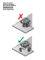


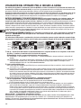


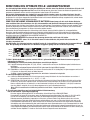
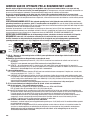


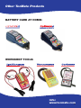

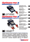

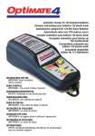
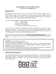
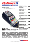

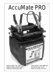
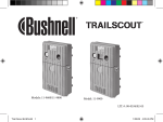
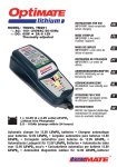
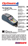
![Acctiva Easy Multicharger 04 / 06 [42,0410,1369]](http://vs1.manualzilla.com/store/data/006735552_1-ebfb9ce13863102a67547e5c99c7ef70-150x150.png)