1
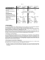
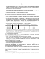
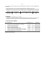
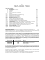
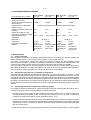
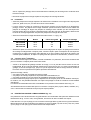
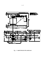
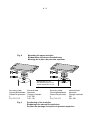
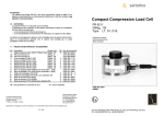
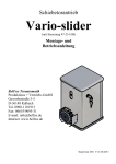
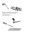
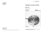
MiniFLEXLOCK PR 6143
Type PR 6143/00N+S
PR 6143/10N+S
9405 361 43.0.
Instruction manual
Gebrauchsanleitung
Mode d’emploi
9499 053 14401
Fifth edition
970515
Philips
Weighing
E W
©Philips Wägetechnik GmbH
Meiendorfer Straße 205, 22145 Hamburg
1997
All rights are strictly reserved.
Reproduction or divulgation in any form whatsoever is not permitted without written authority from the
copyright owner.
Printed in Germany
5th edition
5. Ausgabe
5e tirage
E-1
MiniFLEXLOCK PR 6143
CONTENTS
1
Purpose and application
2.
Technical data
3.
Installation
4.
Maintenance
5.
Spare parts and accessories
E-1
E-2
E-2
E-4
E-4
Fig. 1
Fig. 2
Fig. 3
Fig. 4
Fig. 5
Fig. 6
Fig. 7
Fig. 8
Fig. 9
Fig. 10
A-1
A-1
A-2
A-3
A-4
A-5
A-5
A-6
A-6
A-7
Fig. 11
Fig. 12
Fig. 13
Fig. 14
Fig. 15
Fig. 16
PR 6143
Arrangement of load cells and mounting kits
MiniFLEXLOCK PR 6143/00 N + S
MiniFLEXLOCK PR 6143/10 N + S
Load cell dummy
Loosen the two upper mounting bolts
Position the load cell vertically in the mounting unit
Mounting of the upper load disc
Positioning of the load disc
Insert the load disc in the upper mounting plate and lower the assembly onto the
load cell
Secure the mounting plate in the horizontal position and tighten bolts
Secure the mounting unit horizontally between two parallel surfaces
Tighten the bolts crosswisely (in the order 1...6)
Spare parts and accessories
Permissible inclination
Protection against lift-off
A-7
A-8
A-8
A-9
A - 10
A - 11
1. PURPOSE AND APPLICATION
MiniFLEXLOCK PR 6143 is a mounting kit for PHILIPS PR 6201 load cells with a load rating of 0.5t to 50t,
which also provides horizontal constraining of the object to be weighed. The kit is prepared for construction
of a protection against lifting.
MiniFLEXLOCK is an optimum solution for quick and easy mounting of vessels on three or more load
cells. The examples in Fig. 2 show various solutions for installation of load cells with PR 6143 constraining
units and PR 6145 mounting kits. In order to ensure the required space for movement of the weighing
facility, max. three MiniFLEXLOCK kits may be used for constraining an object. When using a higher
number of load cells than 3, the remaining load cells must be installed with mounting kit PR 6145/00.
Constraining of the object to be weighed is done in X direction (see Fig. 1). The required space for normal
thermal expansion is ensured in Y direction.
Mounting kit
PR 6143/00N
PR 6143/00S
PR 6143/10N
PR 6143/10S
Nominal force
20kN
17kN
50kN
45kN
Material
Steel, zinc-plated, yellow chromated
Stainless steel
Steel, zinc-plated yellow chromated
Stainless steel
A stainless steel pressure plate (marked with "SS") and a food-resistant silicone O-ring (light beige) are
delivered with the stainless steel mounting kits (PR 6143/00S and /10S). These parts must be used
instead of standard pressure plate (without marking) and dark gray standard O-ring.
During transport and installation, the constraining unit is held together by an auxiliary mounting plate, which
must be removed after installation.
Additional hints on load cell arrangement and behaviour with horizontal forces are given in the load cell
operating instructions.
2. TECHNICAL DATA
E-2
For rated load cell capacity
Max. horizontal force in Xdirection (nominal force)
Horizontal destructive load in Xdirection
Max. permitted movement in Ydirection
Thread size for mounting bolts
Minimum rigidity class of
mounting bolts (ISO 898)
Permissible temperature range
Dimensions
Weight (net)
Weight (with packing)
Material
PR 6143/00N
0.5...20t
20kN
PR 6143/00S
0.5...20t
17kN
PR 6143/10N
0.5...50t
50kN
PR 6143/10S
0.5...50t
45kN
>40kN
>40kN
>70kN
>70kN
- limited by the maximum permitted inclination of the load cells M12
5.8
M12
A2
-40°C...+80°C
-40°C...+80°C
see fig. 3
10.5kg
11.6kg
11.3kg
12.4kg
steel, with zinc- stainless steel,
plated surface, 1.4301 acc. to
DIN 17440
yellow
chromated
M14
8.8
M14
A2
-40°C...+80°C
-40°C...+80°C
see fig. 4
15.8kg
17.5kg
17.1kg
19.3kg
steel, with zinc- stainless steel,
plated surface, 1.4301 acc. to
DIN 17440
yellow
chromated
3. INSTALLATION
3.1 Before mounting
To ensure an invariably high weighing accuracy, the foundation for the mounting kit must be horizontal
(use spirit level), flat and rigid for the loads to be supported.
In order to prevent partial overloading of the load cells, the load must be distributed as symmetrical as
possible. Therefore, the foundations of the mounting kits must be aligned and the supporting surfaces of
the weighing object (vessel or platform) must mounted in parallel.
The bore holes of upper and lower mounting plate must coincide. Bolts M12, min. rigidity class 5.8 (to ISO
898) are required for mounting constraining unit PR 6143/00N. For PR 6143/10N, bolts M14, min. rigidity
class 8.8, are required.
3.2 Auxiliary facilities for mounting and alignment
To prevent damage of the load cell due to overload during mounting, dummies instead of load cells (as
shown in Fig. 5) can be used. These dummies must be produced at the site in each individual case. They
are inserted during installation of the mounting kits and ensure exact alignment of mounting kits and
weighing installation. The dummies are replaced by the load cells only when all mechanical and alignment
work as well as welding near the load cell are finished.
3.3 Pre-assembly of mounting kit and load cell
Mounting constraining unit and load cell is done as shown in Fig. 6 to 11 following the mounting hints given
in the load cell operating instructions.
• Release the upper bolts of the auxiliary mounting plate (Fig. 6) and fold the upper mounting plate away.
Insert the dummy, or, if no dummy is provided, the load cell with the load disc as shown in Fig. 7 to 11.
• When using a stainless steel MiniFLEXLOCK (version S), the pressure plate marked with "SS" (Fig. 14,
part 2) and the food-resistant O-ring (light beige) must be used. In this case, the standard pressure
plate (without stamp) and the dark gray standard O-ring are not required.
• Connect upper and lower mounting plate with flexible copper strap (packed with the load cell). Two
bolts M8 and washers for locking are delivered with the mounting kit.
• Re-mount the upper mounting plate at the auxiliary plate.
3.4 Mounting the pre-assembled unit
Mount the pre-assembled unit between horizontally two parallel surfaces.
E-3
• Mount lower and upper mounting plate by means of bolts and washers to foundation and weighing
object support (vessel, platform, etc.).
• When all constraining units and mounting kits are mounted at the weighing facility, remove the auxiliary
mounting plates (tighten the relevant bolts in the threaded holes of the mounting plates) and align the
mounting plates so that the dummies stand uncantedly and in exact vertical position. If required, release
the mounting bolts slightly and adjust the mounting plates. For this purpose, the holes offer some free
space.
• Tighten the mounting bolts crosswisely in the order 1...6 (Fig. 13).
Mounting kit
PR 6143/00N
PR 6143/00S
PR 6143/10N
PR 6143/10S
Bolt
M12
M12
M14
M14
Rigidity class
5.8
A2
8.8
A2
Mounting torque
104Nm
104Nm
165Nm
165Nm
• Only when all welding work near the load cell and mounting and alignment at the object to be weighed
are finished, lift the object and replace the dummy by the load cell. Take care that the load disc is
positioned correctly. The load cell must stand vertically and untiltedly after installation.
3.5 Check after the installation
After the installation of all mounting kits and load cells, the correct mounting must be checked. In
particular, force shunts must be avoided.
• Check, if the constrainer is free of load, i.e. if it can be rotated around its longitudinal axis. If this is not
the case, release the counter-nuts (Fig. 14, part 5) of the constrainer, and turn the hexagon (6), until the
constrainer is free of load. Subsequently, re-tighten the counter nuts and position the swivel bearing
eyes vertically.
After mounting, check by means of Fig. 14,
• if the load cell stands untiltedly in the mounting kit,
• if the upper mounting plate is positioned horizontally, and
• if there is vertical space for movement and the required space for thermal expansion.
The permissible tolerances without considerable effect on the accuracy are given in Fig. 15. The space for
movement required for displacement of the object to be weighed due to thermal expansion, vibration, etc.
can be used only if load cell and constraining unit are installed exactly.
To prevent vertical force shunts, all mechanical connections (pipes, cables, bellows) of the object to be
weighed to its surrounding construction must be as flexible as possible. The overall load must be
supported by the load cells.
E-4
3.6. Protection against lifting
A protection against lifting is generally recommendable. It can be realized as shown in Fig. 16. For this, a
stud, three nuts and two washers are required.
• Take care that the stud (7) has sufficient space for movement in the bore hole (8).
• Counter nuts (9) so that there is a remaining distance (X) of 1mm (± 0.5 mm) to the washer (10). Note
that 1 mm (±0.5) space for lifting is indispensable.
Mounting kit
PR 6143/00
PR 6143/10
Stud
M16
M20
Rigidity class (ISO 898)
5.8
5.8
Permissible load
20kN
50kN
4. MAINTENANCE
• Mounting kits and load cells need no maintenance.
• During a service inspection, the bolts fixing the constrainer must be inspected: every bolt must be fixed
with two safety clips to prevent it from sliding out.
5. SPARE PARTS AND ACCESSORIES
Pos
1
2
3
4
5
6
7
8
9
Description
load disc, standard, PR 6143/50N
load disc, stainless steel, PR 6143/50S
bottom plate with O-ring, standard
bottom plate with O-ring, standard
O-ring, standard (dark grey)
O- ring, food resistance (light beige)
bottom plate with O- ring, stainless steel, PR 6143/24S
bottom plate with O- ring, stainless steel, PR 6143/54S
flexible copper strap, 16mm2, 400mm long
Nom. load
0.5...50t
0.5...50t
0.5...20t
30....50t
0.5...50t
0.5...50t
0.5...20t
30....50t
0.5...50t
Fig.
14 - 1
14 - 1
14 - 2,3
14 - 2,3
14 - 3
14 - 3
14 - 2
14 - 2
14 - 4
Order code
9405 361 43501
9405 361 43502
5322 693 91164
5322 693 91165
5322 532 70298
5322 532 70317
9405 361 43242
9405 361 43542
5322 310 30581
All above mentioned parts are available at the national W service organisations for electronic
weighing.
D-1
MiniFLEXLOCK PR 6143
INHALT
1.
2.
3.
4.
5.
Fig. 1
Fig. 2
Fig. 3
Fig. 4
Fig. 5
Fig. 6
Fig. 7
Fig. 8
Fig. 9
Fig. 10
Fig. 11
Fig. 12
Fig. 13
Fig. 14
Fig. 15
Fig. 16
Zweck und Anwendung
Technische Daten
Installation
Wartung
Ersatzteile und Zubehör
D-1
D-2
D-2
D-4
D-4
PR 6143
Anordnung der Wägezellen und Einbausätze
MiniFLEXLOCK PR 6143/00 N+S
MiniFLEXLOCK PR 6143/10 N+S
Wägezellennachbildung
Lösen der beiden oberen Schrauben
Wägezelle senkrecht einsetzen
Einbauweise des oberen Druckstückes
Einbaulage des oberen Druckstückes
Druckstück in die obere Montageplatte einlegen und Montageeinheit schließen
Obere Montageplatte horizontal ausrichten und Schrauben wieder anziehen
Montageeinheit zwischen zwei horizontal ausgerichteten Montageflächen
montieren
Schrauben über Kreuz anziehen (Reihenfolge 1...6)
Ersatzteile und Zubehör
Maximale Schiefstellung
Abhebesicherung
A-1
A-1
A-2
A-3
A-4
A-5
A-5
A-6
A-6
A-7
A-7
A-8
A-8
A-9
A - 10
A - 11
1. ZWECK UND ANWENDUNG
Die MiniFLEXLOCK PR 6143 ist ein Einbausatz für PHILIPS Wägezellen PR 6201 mit Nennlasten von 0,5t
bis 50t. Gleichzeitig fesselt sie das Wägeobjekt horizontal. Sie ist vorbereitet für den Aufbau einer
Abhebesicherung.
Die MiniFLEXLOCK ist die optimale Lösung, um Behälter schnell und einfach auf drei oder mehr
Wägezellen zu montieren. Fig. 2 zeigt beispielhaft unterschiedliche Anordnungen von Wägezellen mit
Fesselungseinheiten PR 6143 und Einbausätzen PR 6145. Um die erforderliche Bewegungsfreiheit der
Meßeinrichtung zu gewährleisten, dürfen höchstens drei MiniFLEXLOCK zur Fesselung eines
Wägeobjekts eingesetzt werden. Bei Verwendung von mehr als 3 Wägezellen sind die weiteren mit dem
Einbausatz PR 6145/00 zu installieren. Die Fesselung des Wägeobjekts erfolgt in Lenkerlängsrichtung (X
-Richtung), siehe Fig. 1. Die nötige Bewegungsfreiheit für die normale thermische Dehnung ist in der
Lenkerquerrichtung (Y - Richtung) gewährleistet.
Einbausatz
PR 6143/00N
PR 6143/00S
PR 6143/10N
PR 6143/10S
Nennkraft
20kN
17kN
50kN
45kN
Material
Stahl, verzinkt, gelb chromatiert
Edelstahl rostfrei
Stahl, verzinkt, gelb chromatiert
Edelstahl rostfrei
Den Einbausätzen aus rostfreiem Edelstahl (PR 6143/00S und /10S) liegen ein Fußstück aus rostfreiem
Edelstahl (mit "SS" gekennzeichnet) und ein lebensmittelbeständiger Dichtring aus Silikon (hellbeige) bei.
Diese Teile sind anstelle des Standard-Fußstückes (ohne Kennzeichnung) und des dunkelgrauen
Standard-Dichtringes zu verwenden.
Für Transport und Installation wird die Fesselungseinheit von einem Montagehilfsblech zusammengehalten. Dieses muß nach der Installation entfernt werden.
Weitere Hinweise über die Anordnung der Wägezellen und das Verhalten bei Querkräften sind der
Gebrauchsanleitung der verwendeten Wägezelle zu entnehmen.
2. TECHNISCHE DATEN
D-2
für Wägezellen Nennlast
max. Horizontalkraft in XRichtung (Nennkraft)
horizontale Bruchlast in XRichtung
max. erlaubte Bewegung in YRichtung
Gewindegröße der
Montageschrauben
Mindestfestigkeitsklasse der
Montageschrauben (ISO 898)
zulässiger Temperaturbereich
Abmessungen
Gewicht (netto)
Gewicht (mit Verpackung)
Material
PR 6143/00N
0,5...20t
20kN
PR 6143/00S
0,5...20t
17kN
PR 6143/10N
0,5...50t
50kN
PR 6143/10S
0,5...50t
45kN
>40kN
>40kN
>70kN
>70kN
M12
5.8
wird begrenzt durch die maximal
erlaubte Schiefstellung der Wägezellen
M12
M14
M14
A2
-40°C...+80°C
-40°C...+80°C
siehe Fig. 3
10,5kg
11,6kg
11,3kg
12,4kg
rostfreier
Stahl, Oberfläche ver-zinkt, Edelstahl
1.4301 nach
gelb
DIN 17440
chromatiert
8.8
A2
-40°C...+80°C
-40°C...+80°C
siehe Fig. 4
15,8kg
17,5kg
17,1kg
19,3kg
rostfreier
Stahl, Oberfläche ver-zinkt, Edelstahl
1.4301 nach
gelb
DIN 17440
chromatiert
3. INSTALLATION
3.1 Vor der Montage
Für eine gleichbleibende hohe Meßgenauigkeit muß das Fundament für den Einbausatz waagerecht
(Wasserwaage benutzen), eben und unnachgiebig für die vorgesehenen Lasten sein.
Um die Wägezellen nicht partiell zu überlasten, muß die Belastung möglichst gleichmäßig verteilt werden.
Deshalb müssen die Fundamente der Einbausätze auf gleicher Höhe und die Auflageflächen des
Wägeobjekts (Behälter oder Plattform) parallel angeordnet sein.
Die Bohrbilder der oberen und unteren Montageplatte müssen deckungsgleich übereinander liegen. Zur
Montage der Fesselungseinheit PR 6143/00N sind Schrauben M12, Mindest-Festigkeitsklasse 5.8 (nach
ISO 898), für PR 6143/10N Schrauben M14, Mindest-Festigkeitsklasse 8.8 erforderlich.
3.2 Montage- und Ausrichthilfen
Um die Wägezellen bei der Montage nicht durch Überlastungen zu beschädigen, können stattdessen
Stempel als Wägezellennachbildung ähnlich Fig. 5 verwendet werden. Diese sind im Einzelfall vor Ort
anzufertigen. Diese Stempel werden bei der Montage der Einbausätze eingesetzt und gewährleisten eine
genaue Ausrichtung der Einbausätze und der Wägeinstallation. Erst wenn alle mechanischen und
Ausrichtarbeiten sowie alle Schweißarbeiten in der Umgebung der Wägezelle beendet sind, werden die
Wägezellen anstelle der Stempel eingebaut.
3.3 Vormontage von Einbausatz und Wägezelle
Die Montage der Fesselungseinheit und der Wägezelle erfolgt entsprechend Fig. 6 bis 11. Dabei sind die
Montagehinweise in der Gebrauchsanleitung der Wägezelle zu beachten.
• Die oberen Schrauben des Montagehilfsbleches herausdrehen (Fig. 6) und die obere Montageplatte
wegklappen. Stempel oder, wenn nicht vorhanden, Wägezelle mit Druckstück entsprechend Fig. 7 bis
11 einsetzen.
D-3
• Bei Einsatz der MiniFLEXLOCK aus rostfreien Edelstahl (S-Version) sind das der Fesselung beigelegte,
mit "SS" markierte Fußstück (Fig. 14, Teil 2) und der zugehörige nahrungsmittelbeständige Dichtring
(hellbeige) zu verwenden. Das Standard-Fußstück (ohne Stempelung) und der dunkelgraue StandardDichtring werden in diesem Fall nicht benötigt.
• Obere und untere Montageplatte mit flexiblem Kupferkabel verbinden (ist der Wägezelle beigepackt).
Zwei Schrauben M8 und Federringe zur Befestigung sind im Einbausatz enthalten.
• Obere Montageplatte wieder an das Montagehilfsblech schrauben.
3.4 Einbau der vormontierten Einheit
Die vormontierte Einheit zwischen zwei horizontal ausgerichteten Montageflächen montieren.
• Untere und obere Montageplatte mit Schrauben und Federringen an Fundament und WägeobjektAuflage (Behälter, Plattform etc.) anschrauben.
• Erst wenn alle Fesselungseinheiten und Einbausätze an der Wägeeinrichtung montiert sind, die
Montagehilfsbleche entfernen (die zugehörigen Schrauben in die Gewindelöcher der Montageplatten
schrauben) und die Montageplatten so ausrichten, daß die Wägezellennachbildungen bzw.
Wägezellen unverkantet und genau senkrecht stehen. Falls erforderlich, die Montageschrauben etwas
lösen und die Montageplatten verschieben, die Schraubenlöcher bieten etwas Freiraum.
• Montageschrauben kreuzweise in der Reihenfolge 1...6 (Fig. 13) festziehen.
Einbausatz
PR 6143/00N
PR 6143/00S
PR 6143/10N
PR 6143/10S
Schraube
M12
M12
M14
M14
Mindest- Festigkeitsklasse
5.8
A2
8.8
A2
Anzugsmoment
104Nm
104Nm
165Nm
165Nm
• Erst wenn alle Schweißarbeiten in der Nähe der Wägezelle und die Montage- und Ausrichtarbeiten am
Wägeobjekt beendet sind, wird das Wägeobjekt angehoben und die Wägezellennachbildung gegen die
Wägezelle ausgewechselt. Auf die richtige Position des Druckstücks achten. Die Wägezelle muß nach
dem Einbau senkrecht und unverkantet stehen.
3.5 Überprüfung nach dem Einbau
Wenn alle Einbausätze installiert sind, ist der ordnungsgemäße Einbau zu überprüfen. Insbesondere
müssen Kraftnebenschlüsse vermieden werden.
• Prüfen, ob der Lenker lastfrei ist, d.h. sich um seine Längsachse drehen läßt.
Ist das nicht der Fall, die Kontermuttern (Fig. 14, Teil 5) des Lenkers lösen und das Sechskant (6)
verdrehen, bis der Lenker lastfrei ist. Anschließend die Kontermuttern wieder anziehen und die
Gelenkaugen senkrecht stellen.
Weiterhin ist nach der Montage zu überprüfen,
• ob die Wägezelle unverkantet im Einbausatz steht,
• ob die obere Montageplatte waagerecht sitzt und
• ob vertikale Bewegungsfreiheit und das erforderliche Spiel für thermische Dehnung gegeben sind.
Nur bei exakt eingebauter Wägezelle und Fesselungseinheit kann die Bewegungsfreiheit, die für
Verlagerungen des Meßobjekts durch thermische Dehnung, Vibration o.ä. erforderlich ist, ohne
Einschränkung der Meßgenauigkeit genutzt werden.
Fig. 15 zeigt die erlaubten Abweichungen, die zu keiner wesentlichen Beeinflussung der Meßgenauigkeit
führen.
Zur Vermeidung von Kraftnebenschlüssen sind alle Zu- und Ableitungen (Schläuche, Rohre, Kabel) so
flexibel wie möglich an das Meßobjekt zu koppeln. Die gesamte Last muß von den Wägezellen getragen
werden.
3.6 Abhebesicherung (Fig. 16)
Eine Abhebesicherung ist aus Sicherheitsgründen generell empfehlenswert. Diese kann entsprechend
D-4
Fig. 16 verwirklicht werden. Dafür sind eine Gewindestange, drei Muttern und zwei Unterlegscheiben
erforderlich.
• Die Gewindestange (7) muß ausreichend Bewegungsfreiheit in der Bohrung (8) haben.
• Muttern (9) so kontern, daß 1mm (± 0,5 mm) Abstand (X) zur Unterlegscheibe (10) verbleibt. Diese
Hebefreiheit von 1mm (±0,5) ist unbedingt einzuhalten werden, um Kraftnebenschlüsse zu vermeiden.
Einbausatz
PR 6143/00
PR 6143/10
Gewindestange
M16
M20
Festigkeitsklasse (ISO 898)
5.8
5.8
Belastbarkeit
20kN
50kN
4. WARTUNG
• Einbausätze und Wägezellen sind wartungsfrei.
• Im Rahmen einer Service- Überprüfung sind die Haltebolzen des Querlenkers zu inspizieren: jeder
Haltebolzen mit mit zwei Sicherungen, die ihn am Herausrutschen hindern, festgehalten sein.
5. ERSATZTEILE UND ZUBEHÖR
Pos. Bezeichnung
für Laststufe Fig.
Bestell- Nr.
1
Druckstück oben, Standard, PR 6143/50N
0,5...50t
14 - 1
9405 361 43501
2
Druckstück oben, rostfreier Edelstahl, PR 6143/50S
0,5...50t
14 - 1
9405 361 43502
3
Fußstück mit Dichtring, Standard
0,5...20t
14 - 2,3 5322 693 91164
4
Fußstück mit Dichtring, Standard
30....50t
14 - 2,3 5322 693 91165
5
Dichtring, Standard (dunkelgrau)
0,5...50t
14 - 3
5322 532 70298
6
Dichtring, Lebensmittelqualität (hellbeige)
0,5...50t
14 - 3
5322 532 70317
7
Fußstück mit Dichtring, rostfreier Edelstahl, PR 6143/24S
0,5...20t
14 - 2
9405 361 43242
8
Fußstück mit Dichtring, rostfreier Edelstahl, PR 6143/54S
30....50t
14 - 2
9405 361 43542
9
Flexible Kupferleitung 16mm2, 400mm lang
0,5...50t
14 - 4
5322 310 30581
Alle oben aufgeführten Teile können bei den nationalen W Service- Organisationen für
Wägetechnik bestellt werden.
F-1
MiniFLEXLOCK PR 6143
TABLE DES MATIÈRES
1.
But et utilisation
2.
Caractéristiques techniques
3.
Installation
4.
Entretien
5.
Pièces de rechange et accessoires
Fig. 1
Fig. 2
Fig. 3
Fig. 4
Fig. 5
Fig. 6
Fig. 7
Fig. 8
Fig. 9
Fig. 10
Fig. 11
Fig. 12
Fig. 13
Fig. 14
Fig. 15
Fig. 16
F-1
F-2
F-2
F-4
F-4
PR 6143
Disposition de capteurs et de kits de montage
MiniFLEXLOCK PR 6143/00 N+S
MiniFLEXLOCK PR 6143/10 N+S
Mannequin de montage
Desserrer les deux vis supérieures
Insérer le capteur de pesage verticalement
Montage de l’anneau de pression supérieur
Position de montage de l’anneau de pression supérieur
Insérer l’anneau de pression dans la plaque de montage supérieure, et fermer
l’unité de montage
Ajuster la plaque de montage horizontalement, et resserrer les vis
Installer l’unité de montage horizontalement entre deux surfaces parallèles
Serrer les boulons de montage alternativement selon l’ordre 1..6
Pièces de rechange et accessoires
Inclinaison admissible
Protection contre le basculement
A-1
A-1
A-2
A-3
A-4
A-5
A-5
A-6
A-6
A-7
A-7
A-8
A-8
A-9
A - 10
A - 11
1. BUT ET UTILISATION
MiniFLEXLOCK PR 6143 est un kit de montage pour les capteurs de pesage PR 6201 W d'une
capacité nominale de 0,5t à 50t. Ce kit de montage assure également la contrainte horizontale de l'objet
à peser. Il est préparé pour la construction d'une protection contre le basculement.
L'unité MiniFLEXLOCK est une solution optimale pour le montage rapide et facile de réservoirs sur trois
ou plus de capteurs de pesage. Les exemples dans la fig. 2 illustrent plusieurs solutions pour l'installation
de capteurs de pesage avec des unités de contrainte PR 6143 et des kits de montage PR 6145. Afin de
garantir la plage requise pour le mouvement du dispositif de pesage, max. trois kits MiniFLEXLOCK
peuvent être utilisés pour la contrainte d'un objet à peser. Lorsqu'on utilise un nombre plus élevé de 3
capteurs de pesage, les autres capteurs doivent être installés avec le kit de montage PR 6145/00. La
contrainte de l'objet à peser est réalisée dans le sens X (voir la fig. 1). La plage requise pour la dilatation
thermique normale est garantie dans le sens Y.
Kit de montage
PR 6143/00N
PR 6143/00S
PR 6143/10N
PR 6143/10S
Force nominale
20kN
17kN
50kN
45kN
Matière
Acier, passivé au chromate de zinc
Acier inoxydable
Acier, passivé au chromate de zinc
Acier inoxydable
Une plaque de pression en acier inoxydable (marquée *SS+) et un joint torique en silicone résistant aux
produits alimentaires (beige clair) sont livrés avec les kits de montage en acier inoxydable (PR 6143/00S
et /10S). Ces pièces doivent être utilisées au lieu de la plaque de pression standard (non marquée) et du
joint torique standard gris foncé.
Pendant le transport et l'installation, l'unité de contrainte est maintenue par une plaque de montage
auxiliaire. Cette plaque doit être enlevée après l'installation.
Pour des renseignements supplémentaires sur l'arrangement des capteurs de pesage et le comportement
en présence de forces horizontales, voir les mode d'emploi des capteurs de pesage.
F-2
2. CARACTÉRISTIQUES TECHNIQUES
Pour capacités nom. capteur
Force horizontale max dans le
sens X (force nom.)
Charge de rupture horizontale
dans le sens X
Mouvement max. admissible
dans le sens Y
Calibre du filet des boulons de
montage
Classe de rigidité min. des
boulons de montage (ISO 898)
Plage de température
admissible
Dimensions
Poids (net)
Poids (avec emballage)
Matière
PR 6143/00N
0,5...20t
20kN
PR 6143/00S
0,5...20t
17kN
PR 6143/10N
0,5...50t
50kN
PR 6143/10S
0,5...50t
45kN
>40kN
>40kN
>70kN
>70kN
limité par l’inclinaison maximale des capteurs de pesage
M12
M12
M14
M14
5.8
A2
8.8
A2
-40°C...+80°C
-40°C...+80°C
-40°C...+80°C
-40°C...+80°C
voir la fig. 3
10,5kg
11,6kg
11,3kg
12,4kg
acier inoxydable
acier, surface
1.4301 selon
passivée au
DIN 17440
chromate de
zinc
voir la fig. 4
15,8kg
17,5kg
17,1kg
19,3kg
acier
acier, surface
inoxydable
passivée au
1.4301 selon
chromate de
DIN 17440
zinc
3. INSTALLATION
3.1 Avant le montage
Afin de garantir une précision de pesage invariablement élevée, la fondation pour le kit de montage doit
être horizontale (utiliser un niveau d'air), plate et rigide pour les charges prévues.
Pour éviter une surcharge partielle des capteurs de pesage, la charge doit être distribuée le plus
symétriquement possible. A cet effet, les fondations des kits de montage doivent être alignées et les
surfaces portant l'objet à peser (réservoir ou plate-forme) doivent être montées en parallèle.
Les trous dans les plaques de montage supérieure et inférieure doivent coïncider. Utiliser des boulons
M12, classe de rigidité min. 5.8 (selon ISO 898) pour le montage de l'unité de contrainte PR 6143/00N, et
des boulons M14, classe de rigidité min. 8.8, pour le montage de PR 6143/10N.
3.2 Dispositifs auxiliaires pour le montage et l'alignement
Afin d'éviter l'endommagement des capteurs de pesage dû à une surcharge pendant le montage, on peut
utiliser des mannequins de montage au lieu de capteurs de pesage (comme illustrés dans la fig. 5). Ces
mannequins de montage sont à produire sur le site dans chaque cas individuel. Ils sont utilisés pendant
l'installation des kits de montage et garantissent l'alignement exact des kit de montage et de l'installation
de pesage. Les mannequins de montage sont à remplacer par les capteurs de pesage seulement après
avoir achevé tous les travaux mécaniques et les travaux d'alignement et de soudage près du capteur de
pesage.
3.3 Assemblage du kit de montage et du capteur de pesage
Le montage de l'unité de contrainte et du capteur de pesage s'effectue comme illustré dans les fig. 6 à 11
suivant les instructions des notices d'utilisation du capteur de pesage.
• Desserrer les boulons supérieurs de la plaque de montage auxiliaire (Fig. 6) et plier la plaque de
montage supérieure vers le côté. Insérer le mannequin de montage, ou, s'il n'y en a pas, le capteur de
pesage avec la pièce de pression comme illustré dans les fig. 7 à 11.
• Lorsqu'on utilise un MiniFLEXLOCK en acier inoxydable (version S), la plaque de pression marquée
*SS+ (Fig. 14, pièce No. 2) et le joint torique résistant aux produits alimentaires (beige clair) doivent être
utilisés. Dans un tel cas, la plaque de pression standard (sans empreinte) et le joint torique standard
gris ne sont pas requis.
• Relier les plaques de montage supérieure et inférieure à l'aide du câble souple en cuivre (emballé
F-3
avec le capteur de pesage). Deux boulons M8 et des rondelles pour le blocage sont contenues dans
le kit de montage.
• Remonter la plaque de montage supérieure à la plaque de montage auxiliaire.
3.4 Installation
• Visser les plaques de montage supérieure et inférieure à la fondation et au support de l'objet à peser
(réservoir, plate-forme, etc.) à l'aide de boulons et de rondelles.
• Lorsque toutes les unités de contrainte et les kits de montage ont été montés sur le dispositif de
pesage, enlever les plaques de montage auxiliaires (serrer les boulons dans les trous filetés des
plaques de montage) et aligner les plaques de montage d'une manière que les mannequins de
montage soient dans une position horizontale exacte, sans être coincés. Si nécessaire, desserrer les
boulons de montage légèrement et ajuster les plaques de montage dans les trous.
• Serrer les boulons de montage alternativement selon l'ordre 1...6 (Fig. 13).
Kit de montage
PR 6143/00N
PR 6143/00S
PR 6143/10N
PR 6143/10S
Boulon
M12
M12
M14
M14
Classe de rigidité
5.8
A2
8.8
A2
Couple de montage
104Nm
104Nm
165Nm
165Nm
• Seulement après avoir achevé tous les travaux de soudage près du capteur de pesage et les travaux
de montage et d'alignement à l'objet à peser, soulever l'objet à peser et remplacer le mannequin de
montage par le capteur de pesage. Faire attention à ce que la position de la pièce de pression soit
correcte. Après l'installation, le capteur de pesage doit être positionné verticalement, sans être coincé.
3.5 Contrôle après l’installation
Si tous les kits de montage sont installés, contrôler l’installation. En particulier, des erreurs occasionnées
par le connexions à l’objet à peser doivent être évités.
• Vérifier si le dispositif de guidage est libre de charge, c.à.d. s'il peut être tourné autour de son axe
longitudinale. Si ceci n'est pas possible, desserrer les contre-écrous (Fig. 14, pièce 5) du dispositif de
guidage, et tourner l'hexagone (6), jusqu'à ce que le dispositif soit libre de charge. Ensuite, resserrer
les contre-écrous et positionner les paliers pivotants verticalement.
Après le montage, vérifier,
• si le capteur n'est pas coincé dans le kit de montage,
• si la plaque de montage supérieure est positionnée horizontalement, et
• si la plage verticale pour le mouvement et la dilatation thermique est suffisante.
La mise en valeur de la plage requise pour le déplacement de l'objet à peser dû à la dilatation thermique,
la vibration, etc. est possible seulement si le capteur de pesage et l'unité de contrainte ont été installés
exactement.
Les tolérances admissibles sans effet considérable sur la précision sont illustrées dans la fig. 15.
Afin d'éviter des erreurs occasionnées par les connexions à l'objet à peser (tuyaux, câbles, soufflets, etc.),
ceux-ci doivent être raccordés de la façon la plus souple possible.
3.6.
PROTECTION CONTRE LE BASCULEMENT (fig. 16)
Une protection contre le basculement est généralement recommandable. Elle peut être réalisée comme
illustrée dans la fig. 16. Pour cela, une tige filetée, trois écrous et deux rondelles sont requis.
Faire attention à ce que la plage pour le mouvement de la tige filetée (7) dans le trou (8) soit suffisante.
Bloquer les écrous (9) d'une manière que la distance (X) de la rondelle (10) soit d'1mm (± 0,5 mm). Noter
qu'une plage d'1 mm (±0,5) pour le basculement est indispensable.
F-4
Kit de montage
PR 6143/00
PR 6143/10
Tige filetée
M16
M20
Classe de rigidité
(ISO 898)
5.8
5.8
Charge admissible
20kN
50kN
4. ENTRETIEN
• Les kits de montage et les capteurs de pesage ne nécessitent aucun entretien.
• Pendant une inspection de service, les axes du dispositif de guidage doivent être contrôlés: chaque axe
doit être assuré de deux disques de butée.
5 PIÈCES DE RECHANGE ET ACCESSOIRES
Pos.
1
2
3
Description
Charges nominales Fig.
No. de commande
Pièce de pression standard, PR 6143/50N
0,5...50t
14 - 1
9405 361 43501
Pièce de pression, acier inox., PR 6143/50S
0,5...50t
14 - 1
9405 361 43502
Plaque de pression avec joint anneau,
0,5...20t
14 - 2,3 5322 693 91164
standard
4
Plaque de pression avec joint anneau,
30...50t
14 - 2,3 5322 693 91165
standard
5
Joint anneau, standard (gris foncé)
0,5...50t
14 - 3
5322 532 70298
6
Joint anneau, résistant aux produits
0,5...50t
14 - 3
5322 532 70317
alimentaires (beige clair)
7
Plaque de pression, acier inox., PR 6143/24S
0,5...20t
14 - 2
9405 361 43242
8
Plaque de pression, acier inox., PR 6143/54S
30...50t
14 - 2
9405 361 43542
9
Câble souple, cuivre, 16mm2, longueur
0,5...50t
14 - 4
5322 310 30581
400mm
Toutes les pièces mentionnées ci-dessus peuvent être commandées au département SERVICE de
l’organisation nationale pour pesage électronique.
A-2
Fig. 3
MiniFLEXLOCK PR 6143/00 N+S
A-6
Fig. 8
Mounting the upper load disc
Einbauweise des oberen Druckstückes
Montage de la pièce de pression supérieur
All dimensions in mm
Alle Abmessungen in mm
Toutes dimensions en mm
Accuracy class
Genauigkeitsklasse
Classe de précision
L
D1, C1,5, C3
Fig. 9
Nominal load
Nennlast
Charge nominale
0.5t...20t
0.5t...10t
Accuracy class
Genauigkeitsklasse
Classe de précision
L
D1, C1,5, C3
Nominal load
Nennlast
Charge nominale
50t
20t...50t
Positioning of the load disc
Einbaulage des oberen Druckstückes
Position de montage de la pièce de pression supérieur
A-9
Fig. 14
Spare parts and accessories
Ersatzteile und Zubehör
Pièces de rechange et accessoires