1
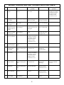
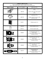
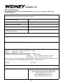
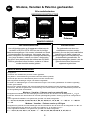
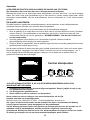
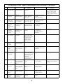
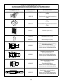
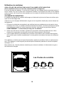
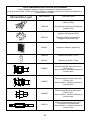
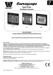
WIDNEY LEISURE LTD.
Modena
GB
Venetian
Palermo
Modena, Venetian & Palermo Gas Fires
All Model Variants
IE
OPERATING INSTRUCTIONS
Page 2
NL
Modena, Venetian & Palermo gashaarden
Alle modelvarianten
BEDIENINGSINSTRUCTIES
Pagina nummer 9
F
Radiateurs à gaz
Modena, Venetian & Palermo
Toutes versions
MODE D'EMPLOI
Page numéro 16
WIDNEY
GB
IE
Modena, Venetian & Palermo Gas Fires
All Model Variants
OPERATING INSTRUCTIONS
Modena
Venetian
Palermo
WARNING
SAFETY GUARD
GAS SAFETY
The guard on this appliance conforms to the requirements of
BS EN 13278: 2003 and satisfies the current fireguard
regulations. The guard is fitted to prevent risk of fire or injury
from burns and must not be removed. It does not give full
protection for young children, the elderly or the infirm. It is
recommended that in circumstances where children, the
elderly or infirm are left unsupervised then an additional
fireguard conforming to BS 8423: 2002 may be required.
This heater must be installed by a
competent gas fitter, working to the Gas
Safety (Installation & Use Regulations,
current edition; the Health & Safety at
Work Act and the manufacturers fitting
instructions.
Read
the
User’s
instructions before operating.
INITIAL LIGHTING
This Appliance must:
Be installed by a Competent person.
Only be used in accordance with these instructions.
Be serviced annually by a Competent person.
Unauthorised tampering must not be permitted.
The air supply inlet and outlet openings must never be obstructed, they should be checked from time to time.
In the event of a gas leak the appliance should be turned “OFF” at its control point. Should the leak persist turn off
the gas supply to the accommodation and contact a Competent person to investigate the fault/leak.
Modena – Venetian – Palermo natural gas version.
The appliance is suitable for use with G20 natural gas at a supply pressure of 20mbar for categories I2H & I2E and
additionally G25 at a supply pressure of 25mbar (pressure couple operates) in the case of category I2E+ and I2L.
The following lists all EC member states, which have a suitable gas supply for each category designation: I2H :- AT, CH, CZ, DK, ES, FI, GB, GR, IE, IT, NO, PT, SE, EE, LT, LV, SI, SK. - I2E :- DE, LU I2E+ :- BE, FR
- I2L :- NL
Modena – Venetian – Palermo LPG gas version.
The appliance is suitable for use with G30 Butane at a supply pressure of 29 mbar for categories I 3B/P & I 3+ and
G31 Propane at 37 mbar for category I 3+ and 30mbar for I 3B/P
The following lists all EC member states, which have a suitable gas supply for each category designation: I 3B/P :- CZ, FI, NL, NO, SE, LT, LV, SI, SK. - I 3+ :- BE, CH, CZ, ES, FR, GB, IE, IT, PT, EE, CY
2
REMOVAL OF THE FIRE FRONT:
Fig 1
Fire front fixing screws
Remove the control knob from the gas valve. Unscrew the 2
cross-headed self-tapping screws, one located in each top corner
of the fire front. (See Fig 1)
Pull the top of the front forward approximately 50mm then lift the
complete front approximately 10mm so that the base of the front is
free of the locating tabs situated at the centre of the base panel.
(See Fig 2)
The fire front can then be lifted free from the main fire chassis.
REPLACING THE FIRE FRONT :
Reverse above procedure taking care to locate the tabs turned up
from the base in the centre slide into the slots in the lower panel
return flange.
Fig 2
REMOVAL AND REPLACEMENT OF THE RADIANTS AND FIREGUARD:
DO NOT ATTEMPT TO REMOVE THE RADIANTS UNLESS YOU UNDERSTAND THESE
INSTRUCTIONS CLEARLY. IF IN DOUBT CONTACT A COMPETENT PERSON.
FIRE GUARD REMOVAL:
CAUTION:
ENSURE THAT THE FIRE IS TURNED OFF AND THE FIRE GUARD IS COOL BEFORE
REMOVING.
THE FIREGUARD MUST NOT BE REMOVED PERMANENTLY.
To Remove the fireguard carefully pull its centre toward you. this will release the locating lugs from
the holes in the chrome trim.
Care should be taken not to distort the Fireguard or damage the chrome trim.
To replace, insert the lugs on one side of the Fireguard into the holes in the chrome trim, bend the
guard slightly so the lugs on the opposite side line up with the holes in the chrome trim, Insert the
lugs and gently push the centre of the guard inward to ensure that all lugs are correctly located.
RADIANT REMOVAL:
Remove the Radiant retention panel by removing the two screws (one at each side).
Lift the centre Radiant up approximately 10mm and pull the base forward to clear the radiant
carrier, and then remove the Radiant. Slide either of the remaining two radiants to the centre and
remove as before, finally repeat the procedure for the one remaining.
RADIANT REPLACEMENT:
Place the first in the centre of the combustion chamber and insert the top edge under the
combustion chamber canopy, then lower the Radiant into the radiant carrier and slide to one side.
Repeat the procedure for the remaining two with the centre radiant being the last one to be fitted.
Replace the radiant retention panel.
3
Fire Operation
READ THESE INSTRUCTIONS BEFORE LIGHTING YOUR FIRE.
(Your installer should give you instruction on how to operate this appliance).
When the fire is first lit, it should be run on high setting for about 1 hour. Ensure the room is well
ventilated and all doors and windows are open, this is to allow for any residual lubricants remaining
from the manufacturing process to burn off.
TO LIGHT THE FIRE:
The fire has an integral ignition system which will light the pilot and main burner flame on initial
lighting.
Ensure that the gas valve is in the off position as indicated in the diagram.
1. Depress the gas control knob and turn anticlockwise rapidly (Two Clicks will be heard). The fire
should now be lit. The main burner and pilot can be viewed via the small round hole in the
chrome trim just in front of the radiants. WARNING: do not get too close to the fire.
2. After rotating the control knob hold in the depressed position for approximately 10 seconds this
will allow the thermocouple safety device to operate.
3. Once lit the fire control can be turned anti-clockwise to full heat or any position between low and
high for the desired output.
If the fire fails to ignite on the first attempt repeat the procedure in rapid succession 3 times. If the fire
has not lit after 3 attempts leave for 5 minutes and repeat steps 1 to 3.
In some cases the fire may need several attempts to ignite if the gas supply has recently been
replaced.
CONTROL POSITIONS
OFF
OFF
PILOT
PILOT/LOW
/LOW
HIGH
HIGH
WHAT TO DO IF YOUR APPLIANCE IS FAULTY OR YOU REQUIRE SPARES.
(DO NOT TAMPER WITH THE FIRE)
1.
2.
3.
Check the simple fault chart to identify the problem, if in doubt consult a competent
person for assistance.
Complete the attached Guarantee Card.
Contact the reseller of the product and request assistance.
Contact your retailer for spare parts as listed.
Useful Numbers and Contact Information:
Widney Leisure Ltd +44(0)1527 577800 Email [email protected]
If you are unable to contact the reseller please contact Widney Leisure directly at the address
listed on the guarantee card.
All Widney products are guaranteed against normal operation for a period of 12 months from
the date of purchase providing they have been installed in accordance with the instructions.
Widney reserve the right to refuse or charge for any work if the above terms are not complied
with.
4
WIDNEY LEISURE GAS FIRE TROUBLE SHOOTING TABLE
Fault
Action
I still have a
problem
Action
I still have a
problem
1
Fire will Not
Ignite
Check gas pressure
at fire
If pressure is correct
see item2
2
The pilot does
not spark
Check spark Gap
Spark Gap is correct
but has no spark
Replace gas valve
and pilot assembly.
As Above
3
Fire Ignition
Sparks but does
not light
Check pilot jet for
blockage
Pilot is clear but no
gas coming through
Check Main Gas
Valve for blockage
As Above
4
Pilot light
ignites but main
burner does not
ignite
Check main injector
for blockage
The main injector is
clear but the fire does
not ignite
Check Main Gas
Valve for Blockage
As Above
5
Main burner
ignites but flame
is very low
Check main injector
for blockage
The main injector is
clear
Check for blockage
in main gas valve
and pipe work
As Above
6
The main gas
valve is blocked
Replace gas valve
See trouble shooting
headings for further
assistance: If Fault
not listed contact:
Widney Leisure
Customer service
7
The gas feed
pipe is blocked
Replace gas feed
pipe
As Above
8
Ceramic Radiant
turning black
(Sooting)
Ensure that no direct
draft is entering the
fire
There are no drafts
around the fire
Check to ensure
radiants are
correctly fitted
As Above
9
The main burner
is blocked
Replace burner
See trouble shooting
headings for further
assistance: If Fault
not listed contact:
Widney Leisure
Customer service
10
Fire burns with
yellow flame
Ensure that no direct
draft is entering the
fire
There are no drafts
around the fire
Check main
injector for
blockage
Contact Widney
Leisure Customer
service
11
Fire Flame
fluctuates
Ensure that no direct
draft is entering the
fire
There is a draft from
the rear of the fire
Contact:
Widney Leisure
Customer service
12
Fire appears to
be overheating
Check gas pressure
at fire
The gas pressure is
correct
Contact:
Widney Leisure
Customer service
13
Fire does not get
hot enough
Check main injector
for blockage
The injector is clear
Check gas pressure
at fire
5
See trouble shooting
headings for further
assistance: If Fault
not listed contact:
Widney Leisure
Customer service
As Above
SHORT PARTS LIST
The illustrated short parts list includes part numbers.
When ordering quote gas fire name with part number & description.
Gas Train
PART NUMBER
DESCRIPTION
W00018
Control Valve with rotary ignition
(LPG)
W00166
Control Valve with rotary ignition
(NG)
W00020
Oxygen depletion device / pilot
assembly (LPG)
W00170
Oxygen depletion device / pilot
assembly (NG)
RA002
Radiant (pack of 3)
W00028
Burner Injector (LPG)
W00167
Burner Injector (NG)
W99901
Straight Terminal with Vent
Plain Finish.
For other finishes please contact
customer services
W99801
Angled Terminal with Vent.
Plain Finish.
For other finishes please contact
customer services
W99600
Straight Terminal Non Vented.
Plain Finish.
For other finishes please contact
customer services
W00213
Terminal with Vent
Pantile Roof
For other finishes please contact
customer services
6
WIDNEY
GUARANTEE
This product is guaranteed against faulty parts or
workmanship for 12 months from the date of purchase,
providing the product is installed in accordance with our
instructions. This guarantee does not extend to light bulbs
which are considered consumable items.
To validate the guarantee the following information must be
supplied. Widney Leisure is not responsible for any cost
incurred in the pursuant of warranty work unless these are
authorised in advance.
When making a claim under warranty you must provide the
details requested opposite otherwise your warranty
might be invalid.
Widney Leisure Ltd. reserves the right to refuse warranty for
any product returned that does not have valid proof
of date of purchase.
This guarantee does not affect your statutory rights.
7
WIDNEY LEISURE LTD
APPLIANCE DETAILS
The information below will be needed by Widney Leisure if you require any servicing or
replacement parts.
Appliance Serial no: This number is found on the data label adhered to the appliance chassis at the
rear (only visible when front case removed). Serial No ……………………………………….
Home Name or Number
Holiday Home Manufactures Name
Holiday Home Serial Number
Date when Home Purchased
Date when Appliance purchased
if different from above.
Address where Fire is located
Your Address:
Describe Type of Fault ( Please describe)
Supply Pressures: I3+ (28 – 37) - I3B/P (28 – 30) - I2H / I2E (20) - I2L / I2E+ (25)
Propane
@ 37mbar +/-2 mbar and 30mbar +/-2 mbar ,
Butane
@ 28mbar +/- 2mbar,
Natural Gas @ 20mbar +/- 1mbar and 25mbar +/- 1mbar
Pressure at control pressure test point: Butane
28 +/- 2mbar
Propane
36.5 +/- 2 mbar, and 29.5 +/- 2mbar
Natural Gas 19.4 +/- 1mbar, and 24 +/- 1mbar
(This pressure should be measured at the appliance when all other appliances are turned on)
Please contact your local Competent Gas Engineer to provide this detail.
Pressure …………………………………………. Gas Type…………………………….
Installation engineers contact details:
Serial number:
WIDNEY LEISURE LTD. SAXON BUSINESS PARK,
HANBURY ROAD, STOKE PRIOR, BROMSGROVE,
WORCESTERSHIRE, B60 4AD ENGLAND
TELEPHONE: 01527 577800
Email: [email protected]
Web: www.widney-leisure.co.uk
8
NL
Modena, Venetian & Palermo gashaarden
Alle modelvarianten
BEDIENINGSINSTRUCTIES
Modena
Palermo
Venetian
WAARSCHUWING
VEILIGHEIDSROOSTER
GASVEILIGHEID
Het veiligheidsrooster op dit apparaat voldoet aan de
vereisten in BS EN 13278: 2003 en aan de huidige
haardroosterregelingen. Het rooster is bedoeld om brand
en brandwonden te voorkomen. Het rooster mag niet
worden verwijderd. Het biedt geen volledige bescherming
voor jonge kinderen, ouderen en zieken. Aanbevolen
wordt een extra haardrooster dat voldoet aan BS 8423:
2002 te gebruiken indien kinderen, ouderen of zieken
zonder toezicht worden gelaten.
De gashaard moet door een
vakbekwame monteur worden
geplaatst, die over de juiste kwalificaties
beschikt en de haard volgens de
geldende regels met inachtneming van
de betreffende gezondheids- en
veiligheidsmaatregelen plaatst. Lees de
gebruiksinstructies alvorens het
apparaat te gebruiken.
EERSTE KEER AANSTEKEN
Dit apparaat:
moet door een vakbekwame persoon worden geplaatst,
mag alleen in overeenstemming met deze instructies worden gebruikt,
moet ieder jaar door een vakbekwame persoon worden onderhouden.
Niet-toegestane handelingen mogen niet worden toegestaan.
De inlaat- en uitlaatopeningen voor de luchttoevoer mogen nooit worden geblokkeerd. Ze moeten regelmatig
worden gecontroleerd.
Mocht er een gaslek optreden, dan moet dit apparaat bij het regelpunt worden afgesloten. Mocht de lekkage
aanhouden, sluit dan de gastoevoer naar de woning af en neem contact op met een vakbekwaam persoon die
de storing/lekkage kan onderzoeken.
Modena – Venetian – Palermo versie op natuurlijk gas
Dit apparaat is bedoeld voor G20 natuurlijk gas onder een druk van 20 mbar voor de categorieën I2H & I2E en
bovendien G25 met een toevoerdruk van 25 mbar (drukkoppeling treedt in werking) ingeval van categorieën I2E+
en I2L.
In de volgende EU-lidstaten is de gastoevoer geschikt voor beide categorieën: I2H :- AT, CH, CZ, DK, ES, FI, GB, GR, IE, IT, NO, PT, SE, EE, LT, LV, SI, SK. - I2E :- DE, LU I2E+ :- BE, FR
- I2L :- NL
Modena – Venetian – Palermo versie op LPG-gas
Dit apparaat is geschikt voor G30 butaangas met een toevoerdruk van 29 mbar voor de categorieën I 3B/P & I 3+ en
G31 propaangas met een druk van 37 mbar voor categorie I 3+ en 30 mbar voor I 3B/P
In de volgende EU-lidstaten is de gastoevoer geschikt voor beide categorieën: I 3B/P :- CZ, FI, NL, NO, SE, LT, LV, SI, SK. - I 3+ :- BE, CH, CZ, ES, FR, GB, IE, IT, PT, EE, CY
9
Fire front fixing screws
VOORPANEEL VERWIJDEREN:
Voorpaneel schroeven
Haal de regelknop van het gasventiel af. Schroef de 2
zelftappende kruiskopschroeven in de bovenhoeken van het
voorpaneel los (zie afb. 1).
Trek de bovenrand van het voorpaneel circa 50 mm naar
voren en til het voorpaneel vervolgens circa 10 mm op, zodat
de onderrand uit de locatietabs in het midden van het
basispaneel komt. (zie afb. 2).
Het voorpaneel kan dan van het gashaardframe worden
gehaald.
zie afb. 1
VOORPANEEL TERUGPLAATSEN:
Voer bovenstaande procedure in omgekeerde volgorde uit.
Let erop dat de tabs in het midden van het basispaneel in de
gleuven van de onderste flens van het voorpaneel vallen.
zie afb. 2
GASBLOKKEN EN HAARDROOSTER VERWIJDEREN EN AANBRENGEN:
VERWIJDER DE GASBLOKKEN ALLEEN WANNEER U DEZE INSTRUCTIES VOLLEDIG
BEGRIJPT. NEEM IN GEVAL VAN TWIJFEL CONTACT OP MET EEN VAKBEKWAAM
PERSOON.
HAARDROOSTER VERWIJDEREN:
LET OP:
CONTROLEER OF DE HAARD IS UITGESCHAKELD EN HET HAARDROOSTER IS
AFGEKOELD, ALVORENS HET ROOSTER TE VERWIJDEREN.
HET HAARDROOSTER MAG NIET PERMANENT WORDEN VERWIJDERD.
Verwijder het haardrooster door het midden ervan voorzichtig naar u toe te trekken. De pasnokken
komen dan uit de gaten in de verchroomde sierlijst.
Let erop dat het haardrooster niet vervormt en dat de sierlijst niet beschadigd raakt.
Plaats het haardrooster terug door de nokken aan een zijde in de gaten de sierlijst te plaatsen. Buig
het rooster een klein beetje, zodat de nokken aan de andere kant in lijn staan met de gaten in de
sierlijst. Steek de nokken in de gaten en duw het midden van het rooster zachtjes naar binnen, zodat
alle nokken correct ingrijpen.
RADIANT VERWIJDEREN:
Verwijder het gasblokhoudpaneel door de twee schroeven te verwijderen (aan beide zijden één).
Til het middelste gasblok circa 10 mm op en trek de onderkant uit de gasblokhouder. Verwijder het
gasblok. Schuif een van beide overige gasblokken naar het midden en verwijder deze op dezelfde
manier. Herhaal deze handelingen voor het laatste gasblok.
GASBLOK TERUGPLAATSEN:
Plaats het eerste gasblok in het midden van de verbrandingskamer en steek de bovenrand onder de
kap van de verbrandingskamer. Laat het gasblok in de houder zakken en schuif hem naar links of
rechts. Herhaal deze handelingen voor de overige twee gasblokken, waarbij de middelste als laatste
wordt aangebracht. Plaats het gasblokhoudpaneel terug.
10
Aansteken
LEES DEZE INSTRUCTIES DOOR ALVORENS DE HAARD AAN TE STEKEN.
(De installateur dient u te laten zien hoe u dit apparaat moet bedienen.)
Wanneer de haard voor de eerste keer wordt aangestoken, zet deze dan circa 1 uur op de hoogste
stand. De ruimte moet goed geventileerd zijn en alle deuren en ramen moeten open staan, zodat
resterende smeermiddelen van het productieproces kunnen verbranden en uit de ruimte worden
gezogen.
DE HAARD AANSTEKEN:
De haard heeft een ingebouwd ontstekingssysteem, dat de waakvlam en de hoofdbrandervlam
aansteekt wanneer de haard voor het eerst wordt aangestoken.
Controleer of het gasventiel in de uit-stand staat; zie de schematische weergave.
1. Druk de gasknop in en draai deze snel met de klok mee (er zijn twee klikken te horen). De haard
moet nu aan zijn. De hoofdbrander en de waakvlam zijn te zien in het kleine ronde gat in de
verchroomde sierlijst net voor de gasblokken. WAARSCHUWING: Niet de dicht in de buurt
van de haard komen.
2. Houd de gasknop na het draaien circa 10 seconden ingedrukt. Hierdoor wordt de
thermokoppeling (de beveiliging) in werking gesteld.
3. Zodra de haard is aangestoken, kan de gasknop tegen de klok mee worden gedraaid naar iedere
gewenste stand tussen laag en hoog.
Als de haard niet direct de eerste keer aan gaat, herhaal de procedure dan 3 keer snel achter elkaar.
Brandt de haard na 3 pogingen niet, laat de haard 5 minuten met rust en herhaal stappen 1 t/m 3.
Het is mogelijk dat er verschillende pogingen nodig zijn om de haard aan te steken indien de
gastoevoer recentelijk werd vervangen.
Control standpunten
OFF
UIT
PILOT
HIGH
WAAK/LAAG
HOOG
/LOW
ALS HET APPARAAT DEFECT IS OF ALS ER RESERVEONDERDELEN NODIG ZIJN
(KNOEI NIET MET DE HAARD)
1. Raadpleeg bij een probleem de eenvoudige storingstabel. Roep bij twijfel de hulp in van
een gekwalificeerde monteur.
2. Vul de bijgesloten garaNtiekaart in.
3. Neem contact op met de verkoper van het product.
Neem contact op met de verkoper voor reserveonderdelen; zie de lijst.
Handige nummers en contactinformatie:
Widney Leisure Ltd +44(0)1527 577800 Email [email protected]
Als u geen contact kunt opnemen met de verkoper, dan kunt u rechtstreeks met Widney
Leisure contact opnemen, zoals aangegeven op de garantiekaart.
Op alle Widney-producten heeft u een garantie op normaal gebruik voor een periode van 12
maanden vanaf de aankoopdatum, mits de producten volgens de instructies zijn
geïnstalleerd. Widney behoudt het recht voor werkzaamheden te weigeren of hiervoor kosten
in rekening te brengen als niet aan bovenstaande bepalingen wordt voldaan.
11
STORINGSCODE TABEL GASHAARD VAN WIDNEY LEISURE
Storing
Handeling
Er is nog steeds een
probleem
Als druk correct is,
zie item2.
1
Haard
ontsteekt niet
Controleer
gasdruk bij haard.
2
De waakvlam
vonkt niet
Controleer
elektrode-afstand.
Elektrode-afstand is
correct, maar er is
geen vonk.
Vervang het gasventiel
met de
waakvlameenheid.
Zie boven.
3
Ontsteking
vonkt, maar
ontsteekt niet
Controleer
waakvlamopening
op verstopping.
Waakvlamopening is
niet verstopt, maar er
stroomt geen gas.
Controleer
hoofdgasventiel op
verstopping.
Zie boven.
4
Waakvlam
ontsteekt,
maar
hoofdbrander
niet
Controleer
hoofdinjector op
verstopping.
Hoofdinjector is niet
verstopt, maar de
haard ontsteekt niet.
Controleer
hoofdgasventiel op
verstopping.
Zie boven.
5
Hoofdbrander
ontsteekt,
maar vlam is
erg laag
Controleer
hoofdinjector op
verstopping.
Hoofdinjector is niet
verstopt.
Controleer op
verstopping in
hoofdgasventiel en
leidingen.
Zie boven.
6
Hoofdgasvent
iel is verstopt.
Vervang
gasventiel.
Zie storingsdiagnoseitems voor verdere
hulp: Staat de storing
er niet bij, neem
contact op met:
Widney Leisure
Customer Service
7
Gastoevoerlei
ding is
verstopt.
Vervang
gastoevoerleiding.
Zie boven.
8
Keramieken
gasblok wordt
zwart
(roetafzetting)
Controleer of er
geen rechtstreekse
tocht op de haard
staat.
Het tocht niet rond de
haard.
Controleer of
gasblokken correct zijn
geplaatst.
Zie boven.
9
De
hoofdbrander
is verstopt.
Vervang brander.
Zie storingsdiagnoseitems voor verdere
hulp: Staat de storing
er niet bij, neem
contact op
met:Widney Leisure
Customer Service
10
Gele vlam
Controleer of er
geen rechtstreekse
tocht op de haard
staat.
Het tocht niet rond de
haard.
Controleer hoofdinjector
op verstopping.
Neem contact op met
Widney Leisure Customer
Service
11
Vlamgroottee
fluctueert
Controleer of er
geen rechtstreekse
tocht op de haard
staat.
Het tocht niet aan de
achterkant van de
haard.
Neem contact op met:
Widney Leisure
Customer Service
12
Haard lijkt
oververhit te
raken
Controleer
gasdruk bij haard.
De gasdruk is correct.
Neem contact op met:
Widney Leisure
Customer Service
13
Haard wordt
niet heet
genoeg
Controleer
hoofdinjector op
verstopping.
Injector is niet
verstopt.
Controleer gasdruk bij
haard.
12
Handeling
Er is nog steeds een
probleem
Zie storingsdiagnose-items
voor verdere hulp: Staat de
storing er niet bij, neem
contact op met: Widney
Leisure Customer Service
Zie boven.
KORTE ONDERDELENLIJST
De korte onderdelenlijst omvat afbeeldingen en onderdeelnummers.
Geef bij bestellingen het onderdeelnummer en de beschrijving door.
Gasgedeelte
ONDERDEELNR.
BESCHRIJVING
W00018
Regelventiel met draai-ontsteking
(LPG)
W00166
Regelventiel met draai-ontsteking
(NG)
W00020
Zuurstofafsluiting/waakvlameenheid
(LPG)
W00170
Zuurstofafsluiting/waakvlameenheid
(NG)
RA002
Gasblok (set van 3)
W00028
Branderinjector (LPG)
W00167
Branderinjector (NG)
W99901
Recht aansluitstuk met ontluchting.
Standaardafwerking.
Neem voor andere afwerkingen
contact op met de klantenservice.
W99801
Hoekstuk met ontluchting.
Standaardafwerking.
Neem voor andere afwerkingen
contact op met de klantenservice.
W99600
Recht aansluitstuk zonder
ontluchting.
Standaardafwerking.
Neem voor andere afwerkingen
contact op met de klantenservice
W00213
Aansluitstuk met ontluchting.
Dakpankap
Neem voor andere afwerkingen
contact op met de klantenservice
13
WIDNEY
GUARANTIE
Op dit product is een garantie van toepassing voor defecte
onderdelen of ondeskundig vakmanschap gedurende 12
maanden na datum van aankoop, mits het product in
overeenstemming met onze instructies is geïnstalleerd.
Deze garantie is niet van toepassing op de gloeilampen
aangezien dit verbruiksartikelen zijn.
Voor het valideren van de garantie moet de volgende
informatie worden doorgegeven. Widney Leisure kan niet
aansprakelijk worden gesteld voor kosten opgelopen als
gevolg van werkzaamheden onder garantie, tenzij deze
vooraf werden geautoriseerd.
Bij een claim onder garantie dient u de hier gevraagde
gegevens door te geven, omdat de garantie anders kan
komen te vervallen.
Widney Leisure Ltd behoudt zich het recht voor garantie te
weigeren op geretourneerde producten waarvoor geen geldig
bewijs van aankoopdatum kan worden overlegd.
Deze garantie is niet van invloed op uw statutaire rechten.
14
WIDNEY LEISURE LTD
APPARAATGEGEVENS
Widney Leisure heeft onderstaande informatie nodig wanneer er een service of
Serienummer apparaat: Dit nummer is te vinden op het label aan de achterkant van het apparaat
(alleen zichtbaar wanneer voorste huis is verwijderd). Serienr. ……………………………………….
Naam of nummer van huis
Naam van vakantiehuisfabrikant
Serienummer vakantiehuis
Aankoopdatum huis
Aankoopdatum apparaat
indien anders dan boven.
Adres waar haard zicht bevindt
Uw adres:
Beschrijving van storing
Toevoerdrukken: I3+ (28 – 37) - I3B/P (28 – 30) - I2H / I2E (20) - I2L / I2E+ (25)
Propaan
@ 37 mbar +/-2 mbar en 30mbar +/-2 mbar
Butaan
@ 28 mbar +/- 2 mbar,
Natuurlijk gas @ 20 mbar +/- 1 mbar en 25 mbar +/- 1 mbar
Druk bij testpunt regeldruk:
Butaan
28 +/- 2 mbar
Propaan
36,5 +/- 2 mbar en 29,5 +/- 2 mbar
Natuurlijk gas 19,4 +/- 1 mbar en 24 +/- 1 mbar
(Deze druk moet worden gemeten bij het apparaat wanneer alle andere apparaten zijn
ingeschakeld.) Neem contact op met de plaatselijke erkende installateur voor deze informatie.
Druk …………………………………………. Gastype…………………………….
Contactgegevens installatiemonteur:
Serienummer:
WIDNEY LEISURE LTD. SAXON BUSINESS
PARK HANBURY ROAD, STOKE PRIOR,
BROMSGROVE, WORCESTERSHIRE. B60 4AD
ENGELAND
TELEFOON: +44 (0)1527 577800
Email: [email protected]
Web: www.widney-leisure.co.uk
15
F
Radiateurs à gaz Modena, Venetian & Palermo
Toutes versions
MODE D'EMPLOI
Modena
Palermo
Venetian
AVERTISSEMENT
GARDE DE SÉCURITÉ
SÉCURITÉ DU GAZ
La garde de sécurité qui équipe ce radiateur est conforme aux
exigences de la norme britannique BS EN 13278: 2003 et à la réglementation en vigueur contre l'incendie. Cette garde est installée
pour éviter tout risque d'incendie ou de brûlure et ne doit pas être
retirée. Elle n'offre pas une protection absolue aux jeunes enfants
ni aux personnes âgées ou infirmes. Au cas où des enfants, des
personnes âgées ou infirmes devraient être laissés sans surveillance à proximité du radiateur, il pourra être nécessaire d'installer
une garde conforme à la norme BS 8423: 2002.
Ce radiateur devrait être installé par
un technicien compétent (accrédité)
qui travaillera en conformité avec la
toute dernière version en vigueur
de la réglementation de sécurité du
gaz et avec les instructions d'utilisation du fabricant. Veuillez lire le
mode d'emploi avant toute utilisation.
ALLUMAGE INITIAL
Cet appareil devra :
Être installé par un technicien compétent.
Être uniquement utilisé en conformité avec les présentes instructions.
Être révisé une fois par an par un technicien compétent.
Toute modification non autorisée est proscrite.
Les orifices d'admission et de sortie d'air ne devront jamais être obstrués, et devront être vérifiés de temps en
temps.
En cas de fuite de gaz, il conviendra de placer la molette de commandes de l'appareil sur « OFF » (ARRÊT). Si
la fuite persiste, coupez l'alimentation en gaz du chalet et contactez un technicien compétent qui effectuera une
recherche approfondie.
Modena – Venetian – Palermo version gaz naturel
Cet appareil est prévu pour être utilisé avec du gaz naturel de type G20 sous une pression de 20mbar pour les
catégories I2H & I2E et
ainsi qu'avec du gaz de type G25 sous une pression de 25mbar (le couple de pression fonctionne) dans le cas
des catégories I2E+ et I2L.
La liste suivante récapitule tous les états membres de l'Union Européenne disposant d'alimentations en gaz
convenables pour chaque catégorie :
I2H :- AT, CH, CZ, DK, ES, FI, GB, GR, IE, IT, NO, PT, SE, EE, LT, LV, SI, SK. - I2E :- DE, LU I2E+ :- BE, FR
- I2L :- NL
Modena – Venetian – Palermo version GPL
Cet appareil est prévu pour être utilisé avec du butane de type G30 sous une pression de 29 mbar pour les
catégories I 3B/P & I 3+ et du propane de type G31 à 37 mbar pour la catégorie I 3+ et 30mbar pour I 3B/P
La liste suivante récapitule tous les états membres de l'Union Européenne disposant d'alimentations en gaz
convenables pour chaque catégorie :
I 3B/P :- CZ, FI, NL, NO, SE, LT, LV, SI, SK. - I 3+ :- BE, CH, CZ, ES, FR, GB, IE, IT, PT, EE, CY
16
RETRAIT DU CADRE FRONTAL:
Fig 1
Fire front fixing screws
Retirez la molette de contrôle de la soupape d'arrivée du gaz.
Desserrez les 2 vis taraudeuses à tête cruciforme situées de
chaque côté, en haut du cadre frontal. (voir la fig. 1)
Tirez le haut du cadre vers l'avant d'environ 50 mm, puis
soulevez l'ensemble du cadre d'environ 10 mm pour faire
sortir la base de ses taquets de fixation, situés au centre du
panneau inférieur. (voir la fig. 2)
Le cadre frontal peut alors être soulevé du châssis principal.
REMISE EN PLACE DU CADRE FRONTAL :
Procédez à l'inverse de ci-dessus, en veillant à bien repositionner les taquets retournés de la base en les faisant glisser
dans les fentes de la bride du panneau inférieur.
Fig 2
RETRAIT ET REMISE EN PLACE DES PANNEAUX RADIANTS ET DE LA GARDE DE
SÉCURITÉ :
NE TENTEZ PAS DE RETIRER LES PANNEAUX RADIANTS SI VOUS NE COMPRENEZ PAS
CLAIREMENT LES PRÉSENTES INSTRUCTIONS. EN CAS DE DOUTES, CONTACTEZ UN
TECHNICIEN COMPÉTENT.
RETRAIT DE LA GARDE DE SÉCURITÉ :
AVERTISSEMENT :
ASSUREZ-VOUS QUE LE RADIATEUR SOIT ÉTEINT ET LAISSEZ À LA GARDE LE TEMPS DE
REFROIDIR AVANT DE LA RETIRER.
LA GARDE DE SÉCURITÉ NE DOIT PAS ÊTRE RETIRÉE DE MANIÈRE PERMANENTE.
Pour enlever la garde de sécurité, tirez avec précaution son centre vers vous. Ceci aura pour effet de
détacher les taquets de fixation des orifices qui se trouvent dans la garniture chromée.
Procédez avec précaution pour ne pas tordre la garde de sécurité ni endommager la garniture chromée.
Pour remettre la garde en place, insérez les taquets d'un côté de la garde dans les orifices de la
garniture chromée, en courbant légèrement la garde pour aligner les taquets du côté opposé avec
leurs trous. Insérez les taquets et poussez doucement le centre de la garde vers l'intérieur pour vous
assurer de correctement les positionner.
RETRAIT DU PANNEAU RADIANT :
Retirez la plaque de rétention du panneau radiant en enlevant les deux vis (une de chaque côté).
soulevez le radiant du centre d'environ 10 mm et tirez la base vers l'avant pour passer au-dessus du
porte-radiant, puis retirez le panneau radiant. Faites glisser l'un ou l'autre des deux radiants restants
vers le centre et retirez-le comme précédemment, enfin répétez la procédure pour le dernier radiant.
REMISE EN PLACE DU PANNEAU RADIANT :
Placez le premier radiant au centre de la chambre de combustion, et insérez le bord supérieur sous
le rebord de la chambre de combustion, puis rabaissez le radiant dans le porte-radiant et faites-le
glisser sur le côté. Répétez la procédure pour les deux autres panneaux radiants restants, celui du
centre étant le dernier à remettre en place. Remettez la plaque de rétention en place.
17
Utilisation du radiateur
VEUILLEZ LIRE CES INSTRUCTIONS AVANT D'ALLUMER VOTRE RADIATEUR.
(Votre installateur devra vous montrer comment utiliser cet appareil).
Lors de l'allumage du radiateur, il convient de le laisser sur son réglage maximum pendant environ 1
heure. Veillez à ce que la pièce soit correctement ventilée et que toutes les portes et les fenêtres
soient ouvertes, afin de pouvoir aérer pendant que les restes de lubrifiant du processus de fabrication brûlent.
ALLUMAGE DU RADIATEUR :
Le radiateur est équipé d'un système d'allumage qui déclenche le pilote et la flamme du brûleur principal lors de l'allumage initial.
Veillez à ce que la soupape d'alimentation en gaz soit sur la position d'arrêt (off), comme indiqué sur
le diagramme.
1. Enfoncez la molette de commande du gaz et faites-la tourner rapidement vers la gauche (vous
entendrez deux clics). Le radiateur devrait maintenant être allumé. Le brûleur principal et le pilote
sont visibles par le petit trou dans la garniture chromée, juste devant les panneaux radiants.
AVERTISSEMENT : ne vous tenez pas trop près du radiateur.
2. Après avoir fait tourner la molette, maintenez-la en position enfoncée pendant environ 10 secondes afin de permettre au dispositif de sécurité à thermocouple de fonctionner.
3. A par le passé allumé la commande de tir peut être tourné dans le sens contraire des aiguilles
d'une montre pour chauffer complètement ou toute position entre bas et haut pour le rendement
désiré
Si le radiateur ne s'allume pas à la première tentative, répétez la procédure 3 fois en rapide succession. Si le radiateur ne s'est toujours pas allumé après 3 tentatives, patientez 5 minutes et répétez
les étapes 1 à 3.
Dans certains cas, il faudra plusieurs tentatives pour allumer le radiateur si l'alimentation en gaz a
été récemment changée.
Les Postes de contrôle
OFF
Arrêt
18
PILOT
Pilote/Basse
/LOW
HIGH
Haut
PROCÉDURE À SUIVRE SI VOTRE APPAREIL EST DÉFECTUEUX OU REQUIERT DES PIÈCES
DÉTACHÉES.
(NE PAS CHERCHER À BRICOLER LE RADIATEUR)
1.
2.
3.
Identifiez le problème dans le tableau des pannes, ou, en cas de doute, consultez un
technicien qualifié.
Remplissez la carte de garantie ci-jointe.
Contactez le revendeur du produit pour assistance.
Contactez votre revendeur pour obtenir des pièces détachées spécifiées dans la liste.
Coordonnées pour contact :
Widney Leisure Ltd +44(0)1527 577800
Email [email protected]
Vous n'êtes pas en mesure de contacter le revendeur, veuillez contacter Widney Leisure directement à l'adresse précisée sur la carte de garantie.
Tous les produits Widney sont garantis pour un usage normal pendant une période de 12
mois à compter de la date d'achat, sous réserve qu'ils aient été installés conformément aux
instructions. Widney se réserve le droit de refuser ou de tarifier les travaux de maintenance si
les modalités précisées ci-dessus n'ont pas été respectées
19
TABLEAU DE DÉPANNAGE DES RADIATEURS WIDNEY LEISURE
Panne
Action
J'ai toujours un
problème
Action
J'ai toujours un
problème
1
Le radiateur de
s'allume pas
Vérifiez la pression au
niveau de l'arrivée de
gaz
Si la pression est correcte,
voir item2
2
Le pilote ne s'allume
pas
Vérifiez l'écart
d'allumage (étincelle)
L'écart d'allumage est
correct, mais aucune
étincelle ne se produit
Changez la soupape
de gaz et le bloc
pilote.
Voir ci-dessus
3
Une étincelle se
produit, mais le
brûleur ne s'allume
pas
Vérifiez que le pilote
ne soit pas bouché
Le pilote est propre, mais le
gaz n'arrive pas
Vérifiez que la
soupape d'arrivée du
gaz ne soit pas
bouchée
Voir ci-dessus
4
Le pilote s'allume,
mais pas le brûleur
principal
Vérifiez que l'injecteur
principal ne soit pas
bouché
L'injecteur principal est
propre mais le radiateur ne
s'allume pas
Vérifiez que la
soupape d'arrivée du
gaz ne soit pas
bouchée
Voir ci-dessus
5
Le brûleur principal
s'allume, mais la
flamme est très
faible
Vérifiez que l'injecteur
principal ne soit pas
bouché
L'injecteur principal est
propre
Vérifiez que la
soupape d'arrivée et la
conduite de gaz ne
soient pas bouchées
Voir ci-dessus
6
La soupape d'arrivée
de gaz est bouchée
Changez la soupape de
gaz.
Voir les autres items du
tableau de dépannage pour
toute assistance
complémentaire. Si la
panne n'apparaît pas dans la
liste, contactez
le service client de Widney
Leisure
La conduite
d'arrivée de gaz est
bouchée
Changez la conduite
d'arrivée de gaz
Voir ci-dessus
8
Le panneau radiant
céramique noircit
(encrassement à la
suie)
Vérifiez que le
radiateur ne soit exposé
à aucun courant d'air
direct
Il n'y a pas de courant d'air
autour du radiateur
Vérifiez que les
panneaux radiants
soient montés
correctement
Voir ci-dessus
9
Le brûleur principal
est bouché
Changez le brûleur
Voir les autres items du
tableau de dépannage pour
toute assistance
complémentaire. Si la
panne n'apparaît pas dans la
liste, contactez
le service client de Widney
Leisure
10
Le radiateur produit
une flamme jaune
Vérifiez que le
radiateur ne soit exposé
à aucun courant d'air
direct
Il n'y a pas de courant d'air
autour du radiateur
Vérifiez que
l'injecteur principal ne
soit pas bouché
Contactez le service
client de Widney
Leisure
11
La flamme est
irrégulière
Vérifiez que le
radiateur ne soit exposé
à aucun courant d'air
direct
Présence d'un courant d'air
provenant de l'arrière du
radiateur
Contactez
le service client de
Widney Leisure
12
Le radiateur semble
surchauffer
Vérifiez la pression au
niveau de l'arrivée de
gaz
La pression du gaz est
correcte
Contactez
le service client de
Widney Leisure
13
Le radiateur ne
chauffe pas assez
Vérifiez que l'injecteur
principal ne soit pas
bouché
L'injecteur est propre
Vérifiez la pression
au niveau de l'arrivée
de gaz
7
20
Voir les autres items
du tableau de
dépannage pour toute
assistance
complémentaire. Si la
panne n'apparaît pas
dans la liste, contactez
le service client de
Widney Leisure
Voir ci-dessus
LISTE ABRÉGÉE DES PIÈCES DÉTACHÉES
La liste abrégée ci-dessous inclut les numéros de référence des pièces.
Lors de la commande, veuillez préciser le modèle du radiateur ainsi que le numéro de référence et
la description de la pièce.
Alimentation gaz
RÉFÉRENCE
DESCRIPTION
W00018
Soupape de contrôle à allumage par
rotation (GPL)
W00166
Soupape de contrôle à allumage par
rotation (GN)
W00020
Dispositif d'appauvrissement en
oxygène / bloc pilote (GPL)
W00170
Dispositif d'appauvrissement en
oxygène / bloc pilote (GN)
RA002
Panneaux radiants (pack de 3)
W00028
Injecteur de brûleur (GPL)
W00167
Injecteur de brûleur (GN)
W99901
Élément terminal droit avec évent,
Finition unie.
Autres finitions : veuillez contacter le
service client
W99801
Élément terminal incliné avec évent,
Finition unie.
Autres finitions : veuillez contacter le
service client
W99600
Élément terminal droit sans évent.
Finition unie.
Autres finitions : veuillez contacter le
service client
W00213
Élément terminal droit avec évent.
Couverture tuiles flamandes
Autres finitions : veuillez contacter le
service client
21
WIDNEY
GARANTIE
Ce produit est garanti 12 mois pièces et main d'œuvre à
compter de la date d'achat, sous réserve qu'il ait été installé
en conformité avec nos instructions. Cette garantie ne
s'étend pas aux ampoules, qui sont considérés comme des
articles relevant de l'usure normale.
Pour valider la garantie, il conviendra de fournir les
informations suivantes. Widney Leisure décline toute
responsabilité pour tous coûts encourus se rapportant à des
travaux normalement couverts par la garantie si ces derniers
n'ont pas été préalablement autorisés.
Pour toute demande dans le cadre de la garantie, veuillez
communiquer les informations demandées au verso, faute de
quoi votre garantie ne sera pas considérée valide.
Widney Leisure Ltd se réserve le droit de refuser d'honorer la
garantie d'un produit qui serait retourné sans preuve d'achat
valide.
Cette garantie n'affecte pas les droits qui vous sont accordés par la
législation en vigueur
22
WIDNEY LEISURE LTD
INFORMATION SUR L'APPAREIL
Les informations ci-dessous sont requises par Widney Leisure pour tous travaux de maintenance ou la fourniture de pièces de rechange.
N° de série de l'appareil : ce numéro se trouve sur la fiche signalétique autocollante apposée à
l'arrière du châssis de l'appareil (uniquement visible une fois le panneau frontal retiré) N° de série
…………………………………...................................................…….
Nom ou numéro du chalet
Fabriquant du chalet
Numéro de série du chalet
Date d'achat du chalet
Date d'achat de l'appareil
si elle diffère de la date précisée
ci-dessus.
Adresse d'installation de l'appareil
Votre adresse :
Description de la panne
Pressions d'alimentation : I3+ (28 – 37) - I3B/P (28 – 30) - I2H / I2E (20) - I2L / I2E+ (25)
Propane :
37mbar +/-2 mbar et 30mbar +/-2 mbar ,
Butane :
28mbar +/- 2mbar,
Gaz naturel : 20mbar +/- 1mbar et 25mbar +/- 1mbar
Pression au point de test de pression de contrôle :Butane
28 +/- 2mbar
Propane
36,5 +/- 2 mbar, et 29,5 +/- 2mbar
Gaz naturel 19,4 +/- 1mbar, et 24 +/- 1mbar
(cette pression devra être mesurée au niveau de l'appareil après avoir allumé tous les autres
appareils). Veuillez contacter votre installateur agréé local pour tous renseignements
complémentaires
Pression …………………………………………. Type de gaz………......................…………………….
Coordonnées de l'installateur :
Numéro de série :
WIDNEY LEISURE LTD. SAXON BUSINESS PARK,
HANBURY ROAD, STOKE PRIOR,
BROMSGROVE, WORCESTERSHIRE. B60 4AD
ANGLETERRE
TÉLÉPHONE: 01527 577800
Email: [email protected]
Web: www.widney-leisure.co.uk
23
SAXON BUSINESS PARK ,
HANBURY ROAD,
STOKE PRIOR, BROMSGROVE,
WORCESTERSHIRE, B60 4AD. ENGLAND
Telephone: + 44 (0)1527 577800
Email: [email protected]
Web: www.widney-leisure.co.uk
Part Number: W00277 Issue D
WIDNEY LEISURE LTD.