1
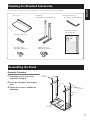
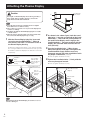
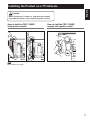
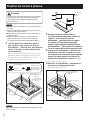
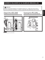
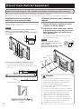
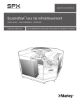
Table top stand
Pied de table
PDK-1016
Operating instructions
Mode d’emploi
Thank you for buying Pioneer’s product.
Please read through the Operating Instructions to learn how
to operate your model safely and properly.
Please be advised to keep the Operating Instructions in your
place for future reference.
Installation
• Consult your dealer if you encounter any difficulties with
this installation.
• Pioneer is not liable for any damage resulting from
improper installation, improper use, modification, or
natural disasters.
IMPORTANT NOTICE
Record the model number and serial number of this
equipment below.
Model No. PDK-1016
Serial No.
Keep these numbers for future use.
Contents
Cautions ...................................................................... 2
Checking the Standard Accessories ......................... 3
Assembling the Stand ............................................... 3
Attaching the Plasma Display ................................... 4
Installing the Product on a TV table etc. ................. 5
Preventing Equipment from Falling Over ................ 6
Specifications ............................................................. 7
Dimensions Diagram ................................................. 7
CAUTION
This symbol refers to a hazard or unsafe practice which
can result in personal injury or property damage.
2
En
Cautions
This product is a table top stand exclusively designed for
Plasma Display (PRO-1140HD) from Pioneer. Use with other
model is capable of resulting in instability causing possible
injury. For further information, please contact the store where
you purchased your display.
Do not install or modify the product other than specified. Do
not use this stand for a Plasma Display other than those
designated and do not modify it or use it for other purposes.
Improper installation is extremely dangerous because it may
result in it falling over or other accident.
Installation Location
• Select a location that is strong enough to support the
weight of the stand and the displays.
• Make sure to place it in a level and stable location.
• Do not install it outdoors, at a hot spring, or near a beach.
• Do not install the stand where it may be subjected to
vibration or shock.
Assembling and Installation
• Assemble the stand in accordance with the assembly
instructions and securely attach all screws at the
designated locations.
There have been cases where unforeseen accidents
such as the equipment breaking or falling over occurred after the installation of the display because the
stand was not installed as instructed.
• The display must always be installed by two or more
people to assure it is installed safely.
• Before installation, turn off the power for the display
and peripheral devices then remove the power cord
plug from the power outlet.
Prevent accidents caused by the product falling over by taking
reliable measures to prevent it from falling over (see Page 6).
English
Checking the Standard Accessories
Check to make sure that you have all the standard accessories before assembly and installation.
• Base cover x 1
• Stand pipes
• Hexagonal wrench x 1
(left and right, interchangeable) x 2
(Opposite side 6 mm for M8 use)
• Operating instructions
(this document) x 1
• Screws (4 x 10 mm) x 4
Table top stand
Pied de table
PDK-1016
• Installation bolts
1
(M8 x 20 mm: black) x 2
• Installation bolts
2
(M8 x 40 mm: black) x 2
Operating instructions
Mode d’emploi
Assembling the Stand
Assembly Procedure
1
Turn the base cover over so the
underside is facing up.
2
Insert the stand pipes into the base
cover.
3
Screws
(4 x 10 mm)
Stand pipe
Tighten the screws to stabilize the
stand pipes.
Screws
(4 x 10 mm)
Stand pipe
Base cover
3
En
Attaching the Plasma Display
Caution
Not applicable
to this model.
A
The weight of a Plasma Display is about 34.1 kg (75.2 lbs), it
has no depth, and are unstable. Therefore, at least two
people must assemble and install them.
A´
A
Note
Insert the bolts in the holes vertically and do not tighten
them with more force than necessary.
Place a sheet or protective cover to protect the display from
scratches or damage.
Assemble only with the Plasma Display lying flat on a table
or similar surface.
Move the stand so that the stand screw holes and the nuts
that connect the main display line up correctly.
1
A´
2
As shown in the above figure, hook the stand
pipe holes A onto the screw heads of the installation bolts 1, then slide the stand upwards to
the main Plasma Display until it engages the
installation bolts 1 (once put together with the
display, the stand will slides no more than 19
mm (3/4 inch)).
3
Pass the installation bolts 2 (M8 x 40 mm:
black) through the stand pipes and tighten the
installation bolts firmly with the accessory
hexagonal wrench (The holes should be used in
the proper combinations, A–A').
With the Plasma Display lying flat, insert and
secure the two Installation bolts 1 (M8 x 20
mm: black) in the holes "a" located in center of
the Plasma Display housing.
At this point, tighten these bolts 1 only until the threads
are no longer visible when viewed from the side (you will
be unable to attach the display if the bolts are screwed in
completely).
Installation
bolt 1
Plasma Display
housing
Be sure to tighten the bolts securely.
Stop screwing
down the bolt
when the threads
are no longer
visible.
4
Tighten the installation bolts 2 firmly with the
accessory hexagonal wrench.
Be sure to tighten the bolts securely.
Installation bolt 1
(M8 x 20 mm: black)
Installation bolts 2
(M8 x 40 mm: black)
(Step 3)
Holes "a"
(holes in center
of Plasma
Display)
Slide the stand
(Step 2)
Plasma Display
Table top stand
Sheet
Note
When laying down the Plasma Display, be careful so as to not
scratch or damage it.
4
En
English
Installing the Product on a TV table etc.
Caution
When installing on a TV table etc., hold the Plasma Display.
If you hold the speakers, they may be damaged or twisted.
How to hold the PRO-1140HD
(side speaker model)
How to hold the PRO-1140HD
(except side speaker model)
Note
Do not hold the side speaker.
5
En
Preventing Equipment from Falling Over
After installing the stand, be sure to take special care to ensure that the equipment will not fall over.
Because of the plasma display’s weight, if it could fall down, this can result in injury.
For safety, be sure to take special care to ensure that the Plasma Display will not fall over.
Using a wall for stabilization
1
Stabilize the equipment as shown in the diagram using
screws that are available on the market.
2
Note
6 mm
(1/4 inch)
9 mm to 15 mm
(3/8 inch to 5/8 inch)
To stabilize the Plasma Display on a TV table, use screws that
have a nominal diameter of 6 mm (1/4 inch).
Select the appropriate screws after consulting a professional
installer if necessary.
Min. 20 mm
(13/16 inch)
Attaching falling prevention bolts (hooks) to
the Plasma Display.
Using strong cords to firmly stabilize it
appropriately and firmly to a wall, pillar, or
other sturdy element.
Perform this work in the same way on the left and right
sides.
Note
Use hooks, cords, and fittings that are
available on the market.
Recommended hook:
Nominal diameter M8
Length 12 mm to 15 mm (1/2 inch to
5/8 inch)
M8
Stabilizing on TV table or other location
12 mm to 15 mm
(1/2 inch to 5/8 inch)
1 Hook
2 Cords
Fittings
Position of table screws
Unit: mm (inch)
552 (21-23/32)
301 (11-27/32)
120
(4-23/32)
24 (15/16)
To stabilize the Plasma Display on a TV table, use screws
that have a nominal diameter of 6 mm (1/4 inch).
11 (13/32)
Dimension without speakers
Side View
6
En
Caution
• A TV table with adequate strength should always be
used to support the Plasma Display.
Failure to do so could result in personal injury and
physical damage.
• If you do not take these precautions, the Plasma
Display could fall down and cause injury.
• The screws, hooks and other fittings that you use to
secure the Plasma Display to prevent it from
overturning will vary according to the composition and
thickness of the surface to which it will be attached.
• Select the appropriate screws, hooks and other fittings
after first inspecting the surface carefully to determine
its thickness and composition and after consulting a
professional installer if necessary.
External dimensions
Weight
English
Specifications
566 mm (W) x 533.5 mm (H) x 325 mm (D) (22-5/16 in. (W) x 21 in. (H) x 12-25/32 in. (D))
4.1 kg (9.1 lbs)
• The above specifications and exterior may be modified without prior notice to improve the product.
Dimensions Diagram
Unit: mm (inch)
PRO-1140HD (side speaker model)
1407 (55-13/12) [Air installation] *1
1379 (54-5/16) [Flush installation] *2
140
(5-1/2)
1244 (48-3/16)
SPEAKER
81
(3-3/16)
20 (13/16)
533.5 (21)
289.5
(11-3/8)
150.5
(5-15/16)
717 (28-7/32)
SPEAKER
57.5
(2-9/32)
127.5 (5)
566 (22-5/16)
325 (12-25/32)
1
* Air installation: Attached with a space of approximately 15 mm between the speakers and the display.
*2 Flush installation: Attached with the speakers in close contact with the display.
PRO-1140HD (except side speaker model)
20 (13/16)
289.5
(11-3/8)
81
(3-3/16)
566 (22-5/16)
533.5 (21)
140
(5-1/2)
150.5
(5-15/16)
717 (28-7/32)
1224 (48-3/16)
57.5
(2-9/32)
127.5 (5)
325 (12-25/32)
Published by Pioneer Corporation.
Copyright © 2006 Pioneer Corporation.
All rights reserved.
7
En
Nous vous remercions d’avoir choisi un produit Pioneer.
Veuillez lire attentivement ce mode d’emploi pour savoir
comment utiliser votre support correctement et en toute
sécurité. Nous vous conseillons de conserver soigneusement
ce mode d’emploi à portée de main et dans un endroit sûr
afin de pouvoir vous y référer le cas échéant.
Installation
• En cas de difficultés, veuillez consulter votre revendeur.
• Pioneer ne saurait être tenu responsable d’aucun
dommage résultant d’une installation ou d’une
utilisation incorrecte de ce produit, de sa modification
ou encore de catastrophes naturelles.
AVIS IMPORTANT
Veuillez prendre note du numéro du modèle et du numéro
de série de cet équipement ci-dessous.
N° du modèle. PDK-1016
N° de série.
Conservez ces numéros pour pouvoir les utiliser
ultérieurement.
Table des matières
Attention ..................................................................... 8
Vérification des pièces fournies ................................ 9
Assemblage du support ............................................ 9
Fixation de l’écran à plasma ................................... 10
Installation du produit sur un meuble de
télévision, etc. .......................................................... 11
Prévenir toute chute de l’équipement ................... 12
Caractéristiques techniques .................................... 13
Schéma de dimensions ........................................... 13
ATTENTION
Ce symbole indique un danger ou une pratique
dangereuse susceptible de provoquer des dommages
corporels ou matériels.
8
Fr
Attention
Ce produit est un pied de table conçu exclusivement pour les
écran à plasma (PRO-1140HD) de marque Pioneer.
L’utilisation de ce produit avec un autre modèle peut être à
l’origine d’un manque de stabilité pouvant provoquer une
blessure. Pour de plus amples informations, veuillez contacter
le magasin où vous avez acheté votre écran.
Ne procédez en aucun cas à installer ou à modifier le produit
autrement qu’en suivant les indications fournies. En outre,
n’utilisez pas ce support pour un écran à plasma autre que
celui pour lequel il a été conçu et ne le modifiez pas ou ne
l’utilisez pas à des fins autres que celles pour lesquelles il a
été conçu.
Une installation incorrecte est extrêmement dangereuse car
elle peut provoquer la chute du support ou tout autre
accident.
Lieu d’installation
• Sélectionnez un emplacement assez solide pour supporter
le poids du support et de l’écran.
• Assurez-vous de placer le produit à un emplacement stable
et plat.
• N’installez pas le support à l’extérieur, à proximité d’une
source thermale ou sur une plage.
• N’installez pas le support à un endroit où il pourrait être
soumis à des chocs ou à des vibrations.
Montage et installation
• Montez le support en suivant les instructions et vissez
solidement toutes les vis aux endroits prévus à cet
effet. Des accidents ont été constatés (casse, chute du
matériel, etc.) suite à l’installation de l’écran parce que
le support n’avait pas été installé conformément aux
instructions.
• Pour une bonne installation, l’écran doit toujours être
installé par au moins deux personnes.
• Avant de procéder à l’installation, mettez l’écran ainsi
que les équipements périphériques hors tension en
coupant l’alimentation, puis retirez la prise du câble
d’alimentation de la prise murale.
Prévenez les accidents causés par la chute du produit
en prenant des mesures fiables visant à éviter toute chute
(voir Page 12).
Vérification des pièces fournies
Veuillez vous assurer que vous possédez bien toutes les pièces nécessaires avant de procéder au montage et à l’installation du
support.
Colonnes de support
(gauche et droite, interchangeables) x 2 unités
Clé hexagonale x 1 unité
(Taille en diagonale 6 mm pour
utilisation M8)
Français
Couverture de table x 1 unité
Mode d’emploi
(ce document) x 1 exemplaire
Vis (4 x 10 mm) x 4 unités
Table top stand
Pied de table
PDK-1016
Vis d’installation 1
(M8 x 20 mm : noir) x 2 unités
Vis d’installation 2
(M8 x 40 mm : noir) x 2 unités
Operating instructions
Mode d’emploi
Assemblage du support
Procédure de montage
1
Tournez le support de couverture de
table de façon à ce que le dessous
regarde vers le haut.
2
Insérez les colonnes de support dans
le support de couverture de table.
3
Serrez les vis afin de stabiliser les
colonnes de support.
Vis
(4 x 10 mm)
Colonne de
support
Vis
(4 x 10 mm)
Colonne de
support
Couverture
de table
9
Fr
Fixation de l’écran à plasma
Attention
Le poids d’un écran à plasma d’environ 34,1 kg. Leur largeur
étant limitée, ils ne sont pas stables. Par conséquent, ils
doivent toujours être assemblés et installés par deux
personnes à la fois.
A´
A
A´
Remarque
Introduisez les vis à la verticale et ne les serrez pas plus que
nécessaire.
Placez une drap ou une bâche afin de protéger l’écran des
éraflures ou autres détériorations.
Montez toujours l’écran à plasma sur une surface plane et
stable uniquement.
Déplacez le support de manière à ce que les fentes du
support destinées à recevoir les vis et les boulons qui
raccordent l’écran principal soient parfaitement alignées.
1
Non-utilisable
pour cette
modéle.
A
Une fois que l’écran à plasma est bien à
plat, veuillez insérer et fixer les deux vis
d’installation 1 (M8 x 20 mm : noir) dans les
fentes "a" placées au centre du boîtier de
l’écran à plasma.
2
3
Puis, serrez les vis 1 jusqu’à ce que les filets ne soient
plus visibles quand vous regardez de côté (il vous sera
impossible de fixer l’écran à plasma si ces vis sont
complètement vissées dans les fentes).
Comme le montre le schéma ci-dessus,
accrochez ensuite les fentes de la colonne de
support A sur les têtes de vis des vis
d’installation 1, puis faites glisser le support
vers le haut sur l’écran à plasma principal
jusqu’à ce que le support s’enclenche dans les
vis d’installation 1 (une fois qu’il est assemblé à
l’écran, le support glisse tout au plus de 19 mm).
Insérez les vis d’installation 2 (M8 x 40 mm :
noir) dans les colonnes de support et serrezles fermement au moyen de la clé hexagonale
fournie (les fentes doivent être utilisées en
fonction des combinaisons correctes A–A').
Veillez à bien serrer les boulons.
Vis d’installation 1
Boîtier de
l’écran à plasma
4
Cessez de visser
davantage les vis
dès que les filets ne
sont plus visibles.
Serrez les vis d’installation 2 fermement au
moyen de la clé hexagonale fournie.
Veillez à bien serrer les boulons.
Vis d’installation 2
(M8 x 40 mm : noir)
(Étape 3)
Vis d’installation 1
(M8 x 20 mm : noir)
Fentes "a"
(fentes dans le
centre de l’écran
à plasma)
Écran à plasma
Pied de table
Drap
Remarque
Veillez à ne pas érafler l’écran plasma ni l’endommager lorsque
vous le couchez.
10
Fr
Faites glisser le support
(Étape 2)
Installation du produit sur un meuble de télévision, etc.
Attention
Comment tenir le PRO-1140HD
(modèle avec enceinte latérale)
Français
Lors de l’installation de l’appareil sur un meuble de télévision, etc., veuillez tenir l’écran à plasma.
Si vous le soulevez par les enceintes, ces derniers risqueraient d’être endommagés ou de se tordre.
Comment tenir le PRO-1140HD
(sauf modèle avec enceinte latérale)
Remarque
Ne soulevez pas par l’enceinte latérale.
11
Fr
Prévenir toute chute de l’équipement
Après avoir installé le support, veillez à prendre les précautions nécessaires pour qu’il ne tombe pas.
En raison de son poids, toute chute de l’écran à plasma risque de blesser quelqu’un.
Pour plus de sécurité, veillez à prendre toutes les mesures nécessaires pour que votre écran à plasma ne chute pas.
Stabilisation sur un meuble de
télévision ou une autre surface
Utilisation d’un mur pour stabiliser le
support
Stabilisez le support comme indiqué sur le schéma à l’aide de
vis vendues dans le commerce.
1
2
Remarque
6 mm
Ces opérations doivent être effectuées de la même
manière à gauche et à droite.
Remarque
Utilisez des crochets, des câbles et
d’autres dispositifs de fixation en vente
dans le commerce.
Crochet recommandé : Diamètre nominal
M8, longueur de 12 mm à 15 mm.
Min. 20 mm
M8
9 mm à 15 mm
Pour stabiliser l’écran à plasma sur un meuble de télévision,
utilisez des vis de 6 mm de diamètre nominal.
Pour sélectionner les vis, consultez si nécessaire un installateur
professionnel.
Fixation des boulons empêchant la chute
(crochets) sur l’écran à plasma.
Utilisation de câbles solides pour stabiliser
le dispositif contre un mur, un pilier ou tout
autre élément stable, avec fermeté et de
façon appropriée.
12 mm à 15 mm
1 Crochet
2 Câble
Position des vis de fixation à la table et au sol
Attache
Pour stabiliser l’écran à plasma sur un meuble de
télévision, utilisez des vis de 6 mm de diamètre nominal.
Unité : mm
24
552
301
120
11
Dimension sans enceinte
Vue latérale
12
Fr
Attention
• Choisissez toujours une table ou une portion du sol
avec une force suffisante pour supporter l’écran à
plasma. Il en résulterait autrement des blessures
corporelles et des dégâts physiques.
• Le cas contraire, l’écran plasma pourrait tomber et
provoquer des dégâts.
• Les vis, crochets et autres raccords que vous utilisez
pour fixer en place l’écran à plasma afin de l’empêcher
de basculer dépendront de la composition et de
l’épaisseur de la surface sur laquelle vous le fixez.
• Sélectionnez les vis, crochets et autres raccords
appropriés après avoir tout d’abord soigneusement
inspecté la surface pour déterminer sa composition et
son épaisseur et après avoir pris contact avec un
installateur professionnel si besoin est.
Caractéristiques techniques
Dimensions extérieures
Poids
566 mm (largeur) x 533,5 mm (hauteur) x 325 mm (profondeur)
4,1 kg
Français
• Les caractéristiques techniques indiquées ci-dessus ainsi que les dimensions extérieures peuvent êtres modifiées sans préavis
en vue d’améliorer le produit.
Schéma de dimensions
Unité : mm
PRO-1140HD (modèle avec enceinte latérale)
1407 (Montage pivotant) *1
1379 (Montage à ras) *2
140
1244
Enceinte
289,5
533,5
150,5
717
Enceinte
81
20
57,5
127,5
566
325
*1 Montage pivotant : fixées à une distance de 15 mm environ entre les enceintes et l’écran.
*2 Montage à ras : fixées avec les enceintes près de l’écran.
PRO-1140HD (sauf modèle avec enceinte latérale)
1224
57,5
81
20
289,5
533,5
150,5
717
140
127,5
566
325
Publication de Pioneer Corporation.
© 2006 Pioneer Corporation.
Tous droits de reproduction et de traduction réservés.
13
Fr
Published by Pioneer Corporation.
Copyright © 2006 Pioneer Corporation.
All rights reserved.
Printed on recycled paper.
Imprimé sur papier recyclé.
PIONEER CORPORATION
4-1, Meguro 1-Chome, Meguro-ku, Tokyo 153-8654, Japan
PIONEER ELECTRONICS (USA) INC.
P.O. BOX 1540, Long Beach, California 90810-1540, U.S.A. TEL: (800) 421-1404
PIONEER ELECTRONICS OF CANADA, INC.
300 Allstate Parkway, Markham, Ontario L3R OP2, Canada TEL: 1-877-283-5901
PIONEER EUROPE NV
Haven 1087, Keetberglaan 1, B-9120 Melsele, Belgium TEL: 03/570.05.11
PIONEER ELECTRONICS ASIACENTRE PTE. LTD.
253 Alexandra Road, #04-01, Singapore 159936 TEL: 65-6472-7555
PIONEER ELECTRONICS AUSTRALIA PTY. LTD.
178-184 Boundary Road, Braeside, Victoria 3195, Australia, TEL: (03) 9586-6300
PIONEER ELECTRONICS DE MEXICO S.A. DE C.V.
Blvd.Manuel Avila Camacho 138 10 piso Col.Lomas de Chapultepec, Mexico,D.F. 11000 TEL: 55-9178-4270
Printed in Japan / Imprimé au Japon <AZR1201-A>