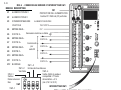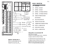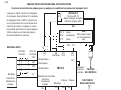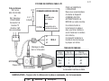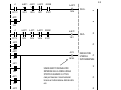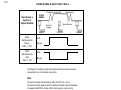
1
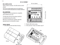
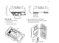
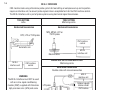
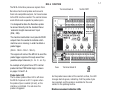
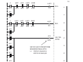
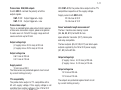
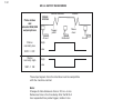
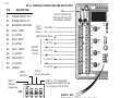
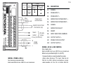
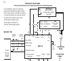
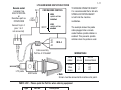
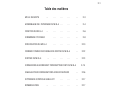
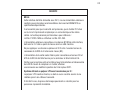
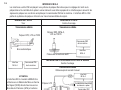
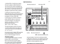
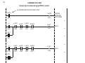
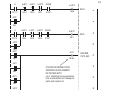
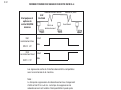
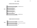
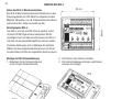
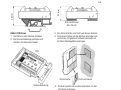
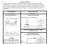
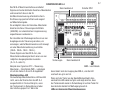
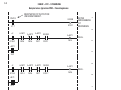
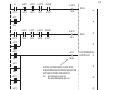
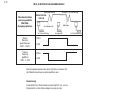
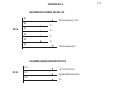
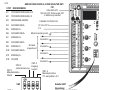
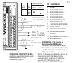
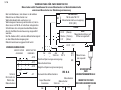
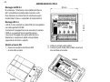
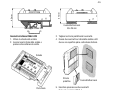
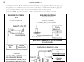
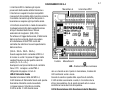
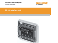
Installation and user’s guide
H-2000-5008-04-E
MI 8-4 interface unit
© 1997 Renishaw. All rights reserved.
Disclaimer
Renishaw® is a registered trademark of
Renishaw plc.
Considerable effort has been made to
ensure that the contents of this document
are free from inaccuracies and omissions.
However, Renishaw makes no warranties
with respect to the contents of this document
and specifically disclaims any implied warranties.
Renishaw reserves the right to
make changes to this document and to the
product described herein without obligation
to notify any person of such changes.
This document may not be copied or
reproduced in whole or in part, or transferred
to any other media or language, by any
means, without the prior written permission
of Renishaw.
The publication of material within this
document does not imply freedom from
the patent rights of Renishaw plc.
Trademarks
All brand names and product names used in
this document are trade names, service marks,
trademarks, or registered trademarks of their
respective owners.
Renishaw part no: H-2000-5008-04-E
Issued: 04. 2003
1-0
Installation and user's guide
MI 8-4 interface unit
English
2-0
Manuel d'installation et d'utilisation
Interface MI 8-4
Français
3-0
Installations– und Benutzerhandbuch
MI 8–4 Schnittstelleneinheit
Deutsch
4-0
Guida d'installazione e d'uso
Interfaccia MI 8–4
Italiano
S2
GB
FCC DECLARATION (USA)
FCC Section 15.19
This device complies with Part 15 of the FCC rules.
Operation is subject to the following two conditions:
1. This device may not cause harmfull interference.
2. This device must accept any interference received,
including interference that may cause undesired
operation.
FCC Section 15.105
This equipment has been tested and found to comply
with the limits for a Class A digital device, pursuant to
Part 15 of the FCC rules. These limits are designed to
provide reasonable protection against harmful
interference when the equipment is operated in a
commercial environment.
This equipment generates, uses, and can radiate radio
frequency energy and, if not installed and used in
accordance with the instruction manual, may cause
harmful interference to radio communications.
Operation of this equipment in a residential area is likely
to cause harmful interference, in which case you will be
required to correct the interference at your own expense.
FCC Section 15.21
The user is cautioned that any changes or modifications
not expressly approved by Renishaw plc, or authorised
representative could void the user's authority to operate
the equipment.
FCC Section 15.27
The user is also cautioned that any peripheral device
installed with this equipment such as a computer, must
be connected with a high-quality shielded cable to insure
compliance with FCC limits.
SAFETY
Information for the user
Replace blown fuses with new components of
the same type. Refer to the SAFETY section of
the relevant product documentation.
Remove power before performing any
maintenance operations.
Refer to the machine supplier's operating
instructions.
Information for the machine supplier
It is the machine supplier's responsibility to
ensure that the user is made aware of any
hazards involved in operation, including those
mentioned in Renishaw product documentation,
and to ensure that adequate guards and safety
interlocks are provided.
Under certain circumstances the probe signal
may falsely indicate a probe seated condition.
Do not rely on probe signals to stop machine
movement.
D
SICHERHEITSANWEISUNGEN
Informationen für den Benutzer
Durchgebrannte Sicherungen müssen mit
gleichwertigen ersetzt werden. Beziehen Sie sich
bitte auf die SICHERHEITSHINWEISE in der
Produktdokumentation.
Vor Wartungsarbeiten muss die Stromversorgung
getrennt werden.
Beziehen Sie sich auf die Wartungsanleitungen des
Lieferanten.
Informationen für den Maschinenlieferanten
Es obliegt dem Maschinenlieferanten, den Anwender
über alle Gefahren, die sich aus dem Betrieb der
Ausrüstung, einschließlich der, die in der Renishaw
Produktdokumentation erwähnt sind, zu
unterrichten und zu versichern, dass ausreichende
Sicherheitsvorrichtungen und Verriegelungen
eingebaut sind.
Unter gewissen Umständen könnte das Messtaster
Fehlsignale melden (Ausgelenkt). Verlassen sie sich
nicht auf das Messtastersignal um die Maschine zu
stoppen.
DK
SIKKERHED
S3
Oplysninger til brugeren
Udskift sikringer, der er sprunget, med nye
komponenter af samme type. Se i afsnittet
SIKKERHED (SAFETY) i produktdokumentationen.
Afbryd strømforsyningen, før der foretages
vedligeholdelse.
Se maskinleverandørens brugervejledning.
Oplysninger til maskinleverandøren
Det er maskinleverandørens ansvar at sikre, at
brugeren er bekendt med eventuelle risici i forbindelse
med driften, herunder de risici, som er nævnt i
Renishaws produktdokumentation, og at sikre, at der
er tilstrækkelig afskærmning og sikkerhedsblokeringer.
Under visse omstændigheder kan probesignalet ved
en fejl angive, at proben står stille. Stol ikke på, at
probesignaler stopper maskinens bevægelse.
S4
E
SEGURIDAD
Información para el usuario
Sustituir los fusibles fundidos con componentes
nuevos del mismo tipo.Remitirse a la sección titulada
SEGURIDAD (SAFETY) en la documentación sobre el
producto.
Quitar la corriente antes de emprender cualquier
operación de mantenimiento.
Remitirse a las instrucciones de manejo del
proveedor de la máquina.
Información para el proveedor de la máquina
Corresponde al proveedor de la máquina asegurar
que el usuario esté consciente de cualquier peligro
que implica el manejo de la máquina, incluyendo los
que se mencionan en la documentación sobre los
productos Renishaw y le corresponde también
asegurarse de proporcionar dispositivos de
protección y dispositivos de bloqueo de seguridad
adecuados.
Bajo determinadas circunstancias la señal de la sonda
puede indicar erroneamente que la sonda está
asentada.No fiarse de las señales de la sonda para
parar el movimiento de la máquina.
F
SECURITE
Informations à l’attention de l’utilisateur
Remplacer les fusibles grillés par des composants
neufs du même type. Consulter la section SECURITE
de votre documentation.
Mettre la machine hors tension avant d’entreprendre
toute opération de maintenance.
Consulter le mode d’emploi du fournisseur de la
machine.
Informations à l’attention du fournisseur de la
machine
Il incombe au fournisseur de la machine d’assurer
que l’utilisateur prenne connaissance des dangers
d’exploitation, y compris ceux décrits dans la
documentation du produit Renishaw, et d’assurer que
des protections et verrouillages de sûreté adéquats
soient prévus.
Dans certains cas, il est possible que le signal issu du
capteur indique à tort que celui-ci est hors matière.
Ne pas se fier aux signaux du capteur qui ne
garantissent pas toujours l’arrêt de la machine.
FIN
TURVALLISUUTTA
Käyttäjälle tarkoitettuja tietoja
Korvaa palaneet sulakkeet samantyyppisillä
uusilla sulakkeilla. Lue tuoteselosteen
TURVALLISUUTTA (SAFETY) koskeva osa.
Kytke virta pois päältä ennen
huoltotoimenpiteitä.
Katso koneen toimittajan käyttöhjeita.
Tietoja koneen toimittajalle
Koneen toimittajan vastuulla on, että käyttäjä
on saanut tiedon mahdollisista käyttöön
liittyvistä vaaroista, mukaan lukien Renishaw’n
tuoteselosteessa mainitut vaarat.
Konetoimittajan tulee myös varmistaa, että
suojukset ja turvalukitukset ovat riittävät.
Tietyissä olosuhteissa anturilta tuleva siganaali
saattaa osoittaa virheellisesti, että anturi on
paikallaan.
S5
S6
I
SICUREZZA
Informazioni per l’utente
I fusibili bruciati dovranno essere sostituiti con altri
dello stesso tipo. Consultare la sezione SICUREZZA
nella documentazione dello specifico prodotto.
Prima di effettuare qualsiasi intervento di
manutenzione, isolare dall’alimentazione di rete.
Consultare le istruzioni d’uso del fabbricante
della macchina.
Informazioni per il fabbricante della macchina
Il fornitore della macchina ha la responsabilità
di avvertire l’utente dei pericoli inerenti al
funzionamento della stessa, compresi quelli
riportati nelle istruzioni della Renishaw, e di for
nire ripari di sicurezza e interruttori di esclusione
adeguati.
È possibile che in certe situazioni venga
erroneamente prodotto un segnale che indica
che la sonda è in posizione. Non fare affidamento
sugli impulsi trasmessi dalla sonda per arrestare
la macchina.
NL
VEILIGHEID
Informatie voor de Gebruiker
Doorgeslagen zekeringen met nieuwe componenten
van hetzelfde type vervangen.U wordt verwezen naar
het hoofdstuk VEILIGHEID (SAFETY) in de
produktendocumentatie.
Voordat u enig onderhoud verricht dient u de
stroom uit te schakelen.
Raadpleeg de bedieningsinstructies van de
machineleverancier.
Informatie voor de Machineleverancier
De leverancier van de machine is ervoor
verantwoordelijk dat de gebruiker op de hoogte
wordt gesteld van de risico’s die verbonden zijn aan
bediening, waaronder de risico’s die vermeld worden
in de produktendocumentatie van Renishaw.
De leverancier dient er tevens voor te zorgen dat
de machine is voorzien van voldoende beveiligingen
en veiligheidsgrendelinrichtingen.
Onder bepaalde omstandigheden kan het
tastersignaal een onjuiste tastertoestand
aangeven.Vertrouw niet op de tastersignalen voor
het stoppen van de machinebeweging.
P
SEGURANÇA
SW
SÅKERHET
Informações para o Utilizador
Substituir fusíveis danificados por novos componentes
do mesmo tipo. Consultar a seção SEGURANÇA
(SAFETY) na documentação do produto.
Information för användaren
Byt ut smälta säkringar med nya av samma typ.
Se avsnittet SÄKERHET (SAFETY) i
produktdokumentationen.
Desligar a alimentação de energia antes de efetuar
qualquer operação de manutenção.
Koppla bort strömmen innan underhåll utförs.
Consultar as instruções de funcionamento do fabricante
da máquina.
Informações para o Fornecedor da Máquina
É responsabilidade do fabricante da máquina assegurar
que o usuário esteja consciente de quaisquer perigos
envolvidos na operação, incluindo os mencionados na
documentação
dos produtos Renishaw e assegurar que são fornecidas
proteções e bloqueios de segurança adequados.
Em determinadas circunstâncias, o sinal do apalpador
pode indicar incorretamente uma condição de toque.
Não confie nos sinais do apalpador para parar o
movimento da máquina.
Se maskintillverkarens bruksanvisning.
Information för maskinleverantören
Maskinleverantören ansvarar för att a
nvändaren informeras om de risker som drift
innebär, inklusive de som nämns i Renishaws
produktdokumentation, samt att tillräckligt goda
skydd och säkerhetsförreglingar tillhandahålls.
Under vissa omständigheter kan sondens signal
falskt ange att en sond är monterad.Lita ej på
sondsignaler för att stoppa maskinens rörelse.
S7
Installation and Users Guide - English
WARRANTY
Equipment requiring attention under warranty
must be returned to your supplier.
No claims will be considered where Renishaw
equipment has been misused, or repairs or
adjustments have been attempted by
unauthorised persons.
CHANGES TO EQUIPMENT
Renishaw reserves the right to change
specifications without notice.
CNC MACHINE
CNC machine tools must always be operated
by competent persons in accordance with
manufacturers instructions.
MI 8-4 MAINTENANCE
No maintenance is required.
ENVIRONMENT
Temperature
The MI 8-4 is specified for storage over
–10° to 70° C (14 to 158° F) and operation
over 0° to 50° C (32° to 122° F) ambient
temperature range.
1-1
Contents
MI 8-4 SAFETY
…
…
…
…
…
1-3
MI 8-4 INTERFACE ASSEMBLY
…
…
…
1-4
MI 8-4 FUNCTION
…
…
…
…
1-6
FANUC OTC CONTROL
…
…
…
…
1-8
MI 8-4 SPECIFICATION
…
…
…
…
1-10
MI 8-4 OUTPUT WAVEFORMS
…
…
…
1-12
MI 8-4 OUTPUTS
…
…
…
1-13
…
MI 8-4 TERMINAL CONNECTIONS AND SWITCH SW1
1-14
WIRING FOR TWO PROBES
…
…
1-16
LP2 HARD WIRED INSPECTION SYSTEM
…
…
1-17
PARTS LIST
…
…
1-17
…
…
…
…
1-2
1-3
SAFETY
MI 8-4
The unit must be supplied from a 24 V d.c. SELV supply complying
with the essential requirements of BSEN61010 or similar specification.
It is essential for continued safety that the on board fuse (FS1)
is replaced by the correct type and rating. Approved parts are
Renishaw, list no. P-FS20-1A25 or Littlefuse, list no. 251 250.
The power supply connected to the power supply terminals of this
unit (B1/B2) must have it's 0 V connected to the machine star point.
Do not exceed 30 V between any terminal and the machine star point
terminal (B3).
The isolated totem-pole output power supply (A10/A12) should be
supplied from the controllers I/O supply and should be current limited
or fused at no more than 8 A.
Ensure the machine tool is in a safe state and power is removed
from the MI 8-4 when changing fuses, making wiring connections,
or changing SW1.
LP2 hard wired inspection system
The probe should not be rotated (spun) by the machine spindle with
the cable connected. If this is allowed, then serious injury could
occur to persons nearby due to flying cable or entanglement.
1-4
MI 8-4 ASSEMBLY
93 mm (3.66 in)
80 mm (3.15 in)
MI 8-4 INSTALLATION
Ideally install the interface in the CNC machine control
cabinet.
Take care to avoid potential sources of interference,
such as three phase transformers and motor controllers.
MI 8-4 MOUNTING
The MI 8-4 is DIN rail mounted and is compatible
with all DIN EN carrier rails.
The alternative dual lock fixing allows the MI 8-4
to be attached to any flat surface.
Both forms of mounting are supplied. Select the
appropriate parts and assemble as shown.
DIN RAIL MOUNT
1. Fit the DIN rail mount onto back of casing.
2. Slide the PCB into the casing,
3. Fit the end cover. Press in to make a snap fit.
PCB
Casing
DIN rail mount
End cover
43 mm (1.69 in)
31 mm (1.22 in)
1-5
DIN rail mount
DUAL LOCK PAD
1. Slide the PCB into the casing,
2. Fit the end cover.
Press in to make a snap fit.
Dual lock pad
50 x 25 mm
(1.96 x 0.98 in)
3. Remove backing strip from dual lock pad.
4. Stick two pads on back of casing and two equally
spaced pads onto flat surface.
PCB
Backing
strip
End cover
Dual lock pad
5. Press the dual lock pads together to mount MI 8-4.
6. Pull apart to remove MI 8-4 from mounting surface.
1-6
MI 8-4 INTERFACE
CNC machine tools using a Renishaw probe system for tool setting or workpiece set-up and inspection
require an interface unit, to convert probe signals into an acceptable form for the CNC machine control.
The MI 8-4 interface unit is part of probe systems using hard wired signal transmission.
TOOL SETTING
Lathe
TOOL SETTING
Machining centre
Hard wired transmission
Hard wired transmission
RP2, LP2 or TS20 probe
MP4, MP6-3, LP2 or
TS27R probe
CNC machine
control
Automatic arm
Machine table
MI 8-4
interface unit
MI 8-4
interface unit
WORKPIECE SET-UP AND INSPECTION
Machining centre
CNC machine
control
Hard wired transmission
Flexible cable with manual connection
WARNING
The MI 8-4 interface must NOT be used
with an in-line signal conditioning
module (SCM) supplied with Renishaw
high precision arms (HPA) and some
TS20 probes.
MI 8-4
interface unit
LP2 probe
Optional spindle
rotation inhibit
CNC machine
control
MA2 holder
1-7
MI 8-4 FUNCTION
The MI 8-4 interface processes signals from
Renishaw hard wired probes and converts
them into compatible outputs, for transmission
to the CNC machine control. The control stores
work offsets and responds to probe inputs.
Terminal block A
Switch SW1
It is designed to allow the Renishaw probe
to connect directly into the standard Fanuc
'automatic length measurement' input
(XAE, ZAE).
The machine tool builder must provide FOUR
outputs from the control to indicate which
machine axis is moving, in order to obtain a
probe trigger.
(SELX– SELX+ SELZ– SELZ+).
This signal will instruct the MI 8-4 to send the
probe trigger signal out through one of four
possible output channels (X– X+ Z– or Z+).
An example of a typical Fanuc OTC control
probe interface PMC ladder logic is shown
on pages 1-8 and 1-9.
Probe status LED
The bi-colour probe status LED is off when
the MI 8-4's power is off. It is green when
the probe stylus is seated (at rest), or the
interface is inhibited. It is red when the
probe is triggered.
When the stylus deflects on contact with a tool
or workpiece the MI 8-4 output changes state,
and the LED changes from green to red.
Fuse
Terminal block B
LED
As the probe moves clear of the contact surface, the LED
changes back to green, indicating that the probe stylus
has reseated, and the probe is available for the next
contact in the probing routine.
Machine movement indicating LEDs
Four green diagnostic LEDs are also provided to
indicate which machine axis is moving.
e.g. During an X– move the X– LED will illuminate.
1-8
FANUC OTC CONTROL
Example of a typical PMC ladder logic diagram
PROBE IS POSITIONED AND READY
➤
1
PINPOS
GOQSM
G132.7
X?.?
OFFSET PAGE
IS FORCED
2
+X
A–MIT1
A+MIT2
A–MIT2
GOQSM
A+MIT1
SELX+
Y82.5
Y82.6
Y82.7
G132.7
–X
A+MIT1
A+MIT2
A–MIT2
G0QSM
G116.3
Y82.4
Y82.6
Y82.7
G132.7
3
G116.2
Y82.4
+MIT1
4
X8.2
5
A–MIT1
SELX–
Y82.5
6
–MIT1
7
X8.3
+Z
A+MIT1
A-MIT1
A–MIT2
G0QSM
G117.2
Y82.4
Y82.5
Y82.7
G132.7
–Z
A+MIT1
A-MIT1
A+MIT2
GOQSM
G117.3
Y82.4
Y82.5
Y82.6
G132.7
1-9
A+MIT2
SELZ+
8
Y82.6
+MIT2
9
X8.4
SELZ–
10
A–MIT2
Y82.7
12
–MIT2
AUTS
X8.2
R518.0
➤
AUX. TOOL
SETTER
13
X8.5
+MIT1
–MIT1
14
X8.3
15
+MIT1
USE THIS FLAG TO PREVENT PROBE
BEING MOVED WHILE ACTIVE
i.e. Inhibit arm movement or
inhibit turret indexing etc.
X8.4
17
X8.5
16
–MIT2
1-10
MI 8-4 SPECIFICATION
Power supply
The MI 8-4 can draw its power from the CNC
machine 24 V nominal d.c. supply. Alternatively
it can be powered from a Renishaw PSU3
power supply unit.
The MI 8-4 input voltage range is 15 to 30 V d.c.
(Supply voltage with ripple -16.5 to 28.5 V with
3 V peak to peak ripple at 100 Hz).
Maximum load with outputs disconnected is 80 mA.
Each XAE/ZAE output connection will add to the
supply current.
Probe input
Normally closed, open for trigger.
Inhibit input
When inhibit is active the outputs are in the seated
state irrespective of the actual probe state.
Two probe operation - toolsetting and inspection
The MI 8-4 has a facility for connecting an output
from a different Renishaw probe system
(i.e. inspection) and then selecting which probe
input (toolsetter or inspection) is routed out through
the outputs. The selection of probe is controlled by a
machine control input to the MI 8-4 (M code).
When the inspection select input is active the
inspection system input is routed through to the
outputs. When inactive the probe input (toolsetter)
is routed through the outputs.
The inspection system input can be driven by
a normally closed relay (open for trigger) or
a totem-pole output (high for triggered).
Inhibit, inspection select and
machine axis moving inputs
These inputs are open collector transistor (OCT), totempole, and relay compatible.
They can be configured as active low or
active high. Also, they can be terminated
by pull-up or pull-down resistors.
With the input resistors common (A9) connected
to 0 V all inputs have 2 k4 pull-down resistors.
With it connected to 15 to 30 V d.c. all inputs
have 2 k4 pull up resistors.
Switch SW1-3 controls the polarity of the input
signals.
SW1-3 OFF
SW1-3 ON
V in low
V in high
= Inputs active high
= Inputs active low
= 4.0 V max
= 11.0 V min
If the inputs are not to be used then SW3-1
should be in the default state of OFF and the
input resistors common (A9) should be
connected to 0 V. This makes all inputs inactive.
1-11
Probe status XAE/ZAE outputs
Switch SW1-1 controls the polarity of all the
output signals.
SW1-1 OFF Output triggered = High
SW1-1 ON Output triggered = Low
Probe status output
This is an isolated totem-pole output which requires
a three wire connection: signal, power and ground.
It works over a 4.75 to 30 V supply range and will
source and sink up to 20 mA.
Output voltage high
(V supply minus 3.5 V max) at 20 mA
(V supply minus 2.8 V max) at 10 mA
Output voltage low
0.6 V max at 20 mA
0.4 V max at 10 mA
Supply current
10 mA max at 30 V
The three wires are protected against short circuit
by current limiting circuitry.
TTL compatibility
The probe status output is TTL compatible with a
5V ±5% supply voltage. If this supply voltage is not
available then another voltage in the 4.75 to 30 V
range can be used with SW1-4 ON.
V out high = 2.5 V min at 2.5 mA.
V out low = 0.4 V max at 10 mA.
With SW1-4 ON, the probe status output will be TTL
compatible irrespective of the supply voltage.
Supply current with SW1-4 ON,
22 mA max at 30 V
15 mA max at 10 V
Fanuc 'automatic length measurement'
The four 'machine axis moving' inputs
(B4, B6, B8, B10) to the MI 8-4 are
open collector transistor (OCT), totem-pole
and relay compatible.
The four outputs (B5, B7, B9, B11) are totem-pole
outputs supplied by the 15 to 30 V power supply
(B1, B2) to the MI 8-4.
Output voltage high
(V supply minus 4.0 V max) at 20 mA.
(V supply minus 3.4 V max) at 10 mA.
Output voltage low
1.5 V max at 20 mA.
1.0 V max at 10 mA.
The outputs are protected against short circuit
by current limiting circuitry.
1-12
MI 8-4 OUTPUT WAVEFORMS
Contact bounce
Probe status
and
selected XAE/ZAE
output options
Move
clear
Trigger
point
At rest
Status
normally low
Reseat
PROBE
STATUS
Deflected
High
Low
SW1-1 OFF
Status
normally high
SW1-1 ON
High
Low
The output signals from the interface must be compatible
with the machine control.
Note:
Change of state debounce time is 20 ms ±5 ms.
Debounce time is the time delay after the MI 8-4
has responded to a probe trigger, before it can
be used again.
At rest
MI 8-4 OUTPUTS
DIAGRAM OF OUTPUTS FOR XAE, ZAE
B1
B7
B9
B11
B2
➤
X–
➤
X+
➤
Z–
➤
Z+
➤
MI 8-4
➤
B5
POWER SUPPLY +24 V
POWER SUPPLY 0 V
DIAGRAM OF PROBE STATUS OUTPUT
A11
A12
+4.75 to 30 V d.c.
➤
PROBE STATUS OUTPUT
➤
MI 8-4
➤
A10
0V
1-13
1-14
PIN
MI 8-4 TERMINAL CONNECTIONS AND SWITCH SW1
DESCRIPTION
FS1
SUPPLY PROTECTION
B1
POWER SUPPLY 24 V
B2
POWER SUPPLY 0 V
B3
MACHINE STAR POINT
B4
SELX– INPUT
B5
X– OUTPUT
B6
SELX+ INPUT
B7
X+ OUTPUT
B8
SELZ– INPUT
B9
Z– OUTPUT
B10 SELZ+ INPUT
250 mA (FF) fuse FS1
mounted in sockets
INPUT
POWER
SUPPLY
15 to 30 V
0V
Machine Star Point
B
X– OUTPUT
INPUTS
M code
driven
X+ OUTPUT
Z– OUTPUT
B11 Z+ OUTPUT
Z+ OUTPUT
B12 SCREEN
SW1-2
See note
SW1-3
Inputs active low
SW1-4 TTL compatible
probe status output with no
+5 V supply (4.75 to 30 V)
SW1-1
outputs
trigger low
SW1
SW1-1
outputs trigger high
SW1-3
inputs active high
SWITCH SW1
Note: SW1-2 should be in the off position.
This switch activates an in-line filter circuit.
It is not to be adjusted by the end user.
1-15
Probe
Terminal Core
LP2 RP2 MP4 TS20
no.
colour MP6-3
TS27R
Blue
2
●
●
Green
3
●
Red
3
●
Blue
Green or red
A
PROBE INPUT
see table above
INSPECTION SYSTEM
STATUS SSR (NC)
Select
M code
driven
Inhibit
0 V or (15 to 30 V)
PIN
DESCRIPTION
A1
SCREEN
A2
PROBE INPUT +
A3
PROBE INPUT –
A4
INSPECTION SYSTEM INPUT +
A5
INSPECTION SYSTEM INPUT –
A6
SCREEN
A7
INSPECTION SELECT
A8
INHIBIT
A9
INPUT RESISTORS COMMON
A10 OUTPUT SUPPLY +
A11 PROBE STATUS OUTPUT
PROBE
STATUS
A12 OUTPUT SUPPLY –
WIRING - MI 8-4 to CNC CONTROL
Use single wires.
Each wire Ø2.5 mm sq. (Ø0.10 in sq.) maximum.
Maximum permitted length 3 m (9.8 ft).
WIRING - PROBE to MI 8-4
Use two core screened cable.
Each core Ø2.5 mm sq. (Ø0.10 in sq.) maximum.
Maximum permitted length 30 m (98 ft).
Screened cable is recommended for probe
status when driving a TTL input. Also for all
MI 8-4 to CNC control connections where
cable lengths of 3 to 10 m (9.8 to 32.8 ft)
are used and interference may be encountered.
1-16
WIRING FOR TWO PROBES
Probe select functions for an inspection probe and a toolsetting probe
For installations where an inspection
probe and a toolsetting probe are fitted
to the same machine, the MI 8-4 features
a circuit that allows the machine control
to select which probe is to be used.
INTERFACE
MI 5 or MI 12
Probe status output
SSR (NC)
NC
OR
An M code will select which
probe signal is sent to the
machine control probe inputs.
24 V
Status (Turquoise)
0V
(Blue)
PROBE
OUTPUTS
A10
A11
A12
Screen
M code
to select
probe
OMI
Probe status
set to
normally low
24 V 0 V
MACHINE TOOL
PROBE
INPUTS
(Pink)
A7
A4
+
A5
–
A6
Screen
B1
24 V
B2
0V
+ve supply
B3
Probe status
–ve supply
Machine
star
point
MI 8-4
INSPECTION
PROBE
Inspection select
Input resistors
common
A9
O V (pull down)
or
24 V (pull up)
Screen
Probe
+
A1
A2
Probe
–
A3
TOOLSETTING
PROBE
1-17
LP2 HARD WIRED INSPECTION SYSTEM
Remote socket
Lemo part no.
EGG 1K 303 CNL
or
Renishaw part no.
P/CN21/0303
24 V
CNC MACHINE CONTROL
HIGH
spindle rotation
inhibited
4 k7
0.25 W
Connect to pin 3
(pins 1 & 2
not connected)
INPUT
LOW
spindle rotation
enabled
A1
A2
A3
3
TO ENSURE OPERATOR SAFETY
It is recommended that a fail safe
SPINDLE ROTATION INHIBIT
is built into the machine
installation.
The example shows the probe
cable plugged into a remote
socket before spindle rotation is
enabled. This prevents spindle
rotation when the probe is used.
MI 8-4
Cable assembly
Part No. A-1016-6451
WIRING TABLE
Wire
colour
* Screen
Blue
Green
LP2 probe
MA2 holder
Plug
pin no
3
1
2
MI 8-4
terminal block
A1
A2
A3
* Note
Screen must be connected to machine star point.
PARTS LIST - Please quote the Part No. when ordering equipment
Type
Part No.
Description
MI 8-4
Fuse
A-2157-0001
P-FS20-1A25
MI 8-4 interface unit.
250 mA (FF) fuse FS1
Manuel d'installation et d'utilisation – Français
GARANTIE
Les équipements défectueux sous garantie doivent
être renvoyés à votre fournisseur.
Aucune réclamation ne sera prise en compte
si l'équipement Renishaw a été mal utilisé ou
si des réparations ou réglages ont été tentés
par des personnes non autorisées.
MODIFICATION DE L'EQUIPEMENT
Renishaw se réserve le droit de modifier les
spécifications sans préavis.
MACHINES CNC
Les machines–outils à CNC doivent uniquement
être utilisées par des opérateurs compétents,
en suivant les consignes du fabricant.
MAINTENANCE DU MI 8-4
Aucune maintenance n'est requise.
ENVIRONNEMENT
Température
Le MI 8–4 doit être stocké à des températures
comprises entre au-dessus de –10° et 70° C et
peut fonctionner à des températures ambiantes
comprises entre 0° et 50° C.
2-1
Table des matières
MI 8-4 SECURITE
…
…
…
…
2-3
ASSEMBLAGE DE L'INTERFACE DU MI 8–4 …
…
…
2-4
FONCTION DU MI 8–4
…
…
…
…
…
…
2-6
COMMANDE OTC FANUC
…
…
…
…
2-8
SPECIFICATION DU MI 8–4
…
…
…
…
2-10
FORMES D'ONDES DES SIGNAUX DE SORTIE DU MI 8–4
…
2-12
SORTIES DU MI 8–4
…
2-13
…
…
…
…
CONNEXIONS AU BORNIER ET INTERRUPTEUR SW1 DU MI 8–4
2-14
CABLAGE POUR CONFIGURATIONS A DEUX PALPEURS
…
2-16
SYSTEME DE CONTROLE CABLE LP2
…
…
…
2-17
NOMENCLATURE
…
…
…
2-17
…
…
2-2
2-3
SECURITE
MI 8-4
Cette interface doit être alimentée sous 24 V, via une alimentation extérieure
conforme aux principales recommandations de la norme BSEN61010 ou
spécifications équivalentes.
Il est essentiel pour que la sécurité soit préservée, que le fusible FS1 situé
sur le circuit imprimé soit remplacé par un autre identique et du même
calibre. Le fusible préconisé par Renishaw a pour référence :
List No P-FS20-1A25 ou Littlefuse List No 251-250.
L'alimentation extérieure connectée sur les bornes B1/B2 de cette interface,
doit avoir le 0 V relié au point de masse commun côté machine.
Ne pas appliquer une tension supérieure à 30 V entre l'une des bornes de
connexion de la MI 8-4 et la borne de masse (B3).
L'alimentation de la sortie isolée "totem-pole" connectée aux bornes A10 et
A12 de la MI 8-4 doit être fournie par le controleur et être limitée à 8 A.
Vérifier que la machine outil est arrêtée et que l'alimentation est déconnectée
de la MI 8-4 avant de remplacer un fusible, effectuer
une connexion ou modifier la position de l'interrupteur SW1.
Système utilisant un palpeur LP2 avec transmission par fil :
Le palpeur LP2 monté en broche, ne doit en aucun cas être soumis à une
rotation quand son câble est connecté.
Si tel était le cas, de graves dommages pourraient en résulter pour les
personnes à proximité immédiate.
2-4
ASSEMBLAGE DU MI 8–4
93 mm
Montage du MI 8–4
Le MI 8–4 se monte sur rails DIN et est compatible
avec tous les rails porteurs DIN EN.
La fixation alternative Dual Lock permet au MI 8–4
d'être fixée sur n'importe quelle surface plane.
Les deux formes de montage sont fournies.
Sélectionner les pièces appropriées et assembler
comme cela est montré.
Montage sur rails DIN
1. Monter le support de DIN Rail à l'arrière
du boîtier.
80 mm
Installation du MI 8-4
Il convient de monter l'interface dans l'armoire
de commande de la machine–outil.
Veiller à éviter les sources éventuelles
d'interférence telles que les transformateurs
triphasés et les contrôleurs moteur.
2. Faire glisser la Plaquette de Circuits
Imprimés dans le boîtier.
3. Monter le couvercle d'extrémité.
Appuyer dessus pour un montage rapide.
Plaquette de
Circuit Imprimés
Boîtier
Montage sur rail DIN
Capot d'extrémité
43 mm
31 mm
2-5
Montage sur rail DIN
Tampon DUAL LOCK
1. Faire glisser la Plaquette de Circuits
Imprimés dans le boîtier
2. Monter le couvercle d'extrémité.
Appuyer dessus pour un montage rapide.
Tampon Dual Lock
60 x 26 mm
3. Oter la bande arrière du Tampon Dual Lock
4. Coller deux tampons sur l'arrière du boîter et les deux
autres espacés de façon égale sur la surface plane.
Bande arrière
Plaquette de
Circuit Imprimé
Capot d'extrémité
Tampon Dual Lock
5. Presser les tampons Dual Lock les uns contre les autres
pour monter le MI 8-4.
6. Séparer les tampons pour enlever le MI 8-4 de la surface.
2-6
INTERFACE MI 8-4
Les machines–outils CNC employant un système de palpeur Renishaw pour le réglage de l'outil ou la
préparation et le contrôle de la pièce à usiner doivent aussi être équipées d'un interface pour convertir les
signaux du palpeur en une forme acceptée par la commande CNC de la machine. L'interface MI 8–4 fait
partie de systèmes de palpeur utilisant une transmission câblée de signal.
REGLAGE DE L'OUTIL
Centre d'usinage
REGLAGE DE L'OUTIL
Tour
Transmission câblée
Transmission câblée
Palpeur RP2, LP2 ou TS20
Palpeur MP4, MP6–3,
LP2 ou TS27R
Commande CNC
de la machine
Bras automatique
Plateau de la machine–outil
Interface
MI 8–4
Commande CNC
de la machine
Interface
MI 8–4
INSTALLATION ET CONTROLE DE LA PIECE A USINER
Centre d'usinage
Transmission câblée
Câble souple à raccord manuel
Interface
MI 8–4
ATTENTION
L'interface MI 8–4 ne doit JAMAIS être
utilisé avec un Module de Mise en Forme
de Signal (SCM) directe fourni avec les
Bras Haute Précision (HPA) et certains
palpeurs TS20 Renishaw.
Palpeur LP2
Immobilisation automatique
de la broche – option
Commande CNC
de la machine
Porte–outil MA2
2-7
FONCTION DU MI 8–4
L'interface MI 8–4 transforme les signaux
émis par les palpeurs câblés Renishaw et
les convertit en des sorties compatibles qui
sont ensuite transmises à la commande CNC
de la machine. La commande mémorise les
décalages et répond aux entrées du palpeur.
Bloc de connexions A
Interrupteur SW1
L'interface est conçu pour permettre au
palpeur Renishaw de se connecter directement
à l'entrée standard de "Mesure Automatique
de Longueur" du Fanuc (XAE, ZAE).
Le constructeur de la machine–outil devra
prévoir QUATRE sorties au niveau de la
commande indiquant l'axe mobile de la
machine, pour obtenir un signal de
déclenchement de palpeur.
(SELX– SELX+ SELZ– SELZ+).
Ce signal demandera au MI 8–4 d'envoyer
un signal de déclenchement de palpeur sur
un des quatre canaux de sortie disponibles
(X–, X+, Z– ou Z+).
Un exemple type de la logique PMC en échelle
d'une interface palpeur à commande OTC
Fanuc est donné aux pages 2–8 et 2–9.
LED d'état de palpeur
La LED bicolore d'état de palpeur est éteinte
lorsque le MI 8–4 est hors tension.
Elle est verte lorsque le stylet du palpeur
est au repos ou que l'interface est désactivé,
et rouge lorsque le palpeur est déclenché.
Lorsque le stylet dévie au contact d'un outil
ou d'une pièce à usiner, la sortie du MI 8–4
change d'état et la LED passe du vert au rouge.
Fusible
Bloc de connexions B
LED - diode électroluminescente
Lorsque le palpeur s'écarte de la surface de contact,
la LED passe à nouveau au vert, signalant que le stylet
du palpeur s'est remis en place et que le palpeur est
prêt pour le contact programmé suivant.
LED d'indication des mouvements machine
Quatre LED vertes de diagnostic sont aussi prévues
pour l'axe mobile de la machine. Par exemple, pour un
déplacement sur l'axe X–, la LED X– s'allumera signaler.
2-8
COMMANDE OTC FANUC
Exemple type de schéma de logique PMC en échelle
LE PALPEUR EST EN POSITION ET PRET
➤
GOQSM
G132.7
X?.?
PAGE DE
DECALAGE
EST FORCEE
1
PINPOS
2
+X
A–MIT1
A+MIT2
A–MIT2
GOQSM
A+MIT1
SELX+
Y82.5
Y82.6
Y82.7
G132.7
–X
A+MIT1
A+MIT2
A–MIT2
G0QSM
G116.3
Y82.4
Y82.6
Y82.7
G132.7
3
G116.2
Y82.4
+MIT1
4
X8.2
5
A–MIT1
SELX–
Y82.5
6
–MIT1
7
X8.3
+Z
A+MIT1
A-MIT1
A–MIT2
G0QSM
G117.2
Y82.4
Y82.5
Y82.7
G132.7
–Z
A+MIT1
A-MIT1
A+MIT2
GOQSM
G117.3
Y82.4
Y82.5
Y82.6
G132.7
2-9
A+MIT2
SELZ+
8
Y82.6
+MIT2
9
X8.4
SELZ–
10
A–MIT2
Y82.7
12
–MIT2
AUTS
X8.2
R518.0
➤
REGLEUR
OUTIL AUX
13
X8.5
+MIT1
–MIT1
15
+MIT1
UTILISER CE DRAPEAU POUR
INTERDIRE LE DEPLACEMENT
DU PALPEUR ACTIF
c.à.d. Interdiction du mouvement du
bras ou interdiction de l'indexage du
porte–outil revolver etc.
14
X8.3
X8.4
17
X8.5
16
–MIT2
2-10
SPECIFICATION DU MI 8–4
Alimentation
Le MI 8–4 peut tirer sa puissance de l'alimentation en
24 V nominal CC de la machine CNC. Autrement,
il peut être mis sous tension par un bloc
d'alimentation PSU3.
La gamme de tension d'entrée du MI 8–4 est de
15 V à 30 V CC. (Tension d'alimentation avec une
ondulation de – 16,5 à 28,5 V avec une ondulation
crête à crête de 3 V à 100 Hz).
La charge maximale avec les sorties déconnectées
est de 80 mA. Chaque connexion de sortie XAE/ZAE
augmentera le courant d'alimentation.
Entrée du palpeur
Normalement fermé, ouvert pour déclenchement.
Entrée du signal d'interdiction
Lorsque le signal d'interdiction est actif, les sorties
sont dans un état de repos indépendamment de
l'état en cours du palpeur.
Fonctionnement à deux palpeurs – réglage d'outil
et contrôle
Le MI 8–4 possède un dispositif pour connecter une
sortie venant d'un système de palpeur Renishaw
différent (c'est à dire le contrôle) et ensuite pour
sélectionner quelle entrée de palpeur (réglage
d'outil ou contrôle) est envoyé vers les sorties.
La sélection du palpeur est commandée par l'entrée
de la commande de la machine au MI 8–4 (Code M).
Lorsque l'entrée de Sélectionner le contrôle est
active, l'entrée du système de contrôle est envoyée
vers les sorties. L'entrée du palpeur (réglage d'outil)
Fonctionnement à deux palpeurs – suite
lorsqu'elle est inactive, est envoyée vers les sorties.
L'entrée du système de contrôle peut être entraînée
par un relais normalement fermé (ouvert pour le
déclenchement) ou par une sortie totem-pole
(haute pour déclenchement).
Interruption, sélectionner le contrôle et
entrées de mouvement des axes de la machine
Ces entrées sont un transistor à collecteur ouvert
(OCT), un totem-pole, et un relais compatible.
Ils peuvent être configurés comme actif bas ou
actif haut. Ils peuvent également être terminés par
des résistances chutrices ou montantes.
Avec le commun des résistances d'entrée (A9)
connecté au 0 V, toutes les entrées ont des
résistances chutrices de 2,4 k. Lorsqu'il est
connecté du 15 V au 30 V CC, toutes les entrées
ont des résistances montantes de 2,4 k.
L'interrupteur SW1–3 commande la polarité
des signaux d'entrée.
SW1–3 ARRET = Entrées actives hautes
SW1–3 MARCHE = Entrées actives basses
Tension en bas = 4,0 V max.
Tension en haut = 11,0 V min.
Si les entrées ne sont pas à être utilisées, alors le
SW3–1 devra être dans un état par défaut d'ARRET
et le commun des résistances d'entrée (A9) devra
être connecté au zéro. Ceci rend toutes les entrées
inactives.
2-11
Sorties XAE/ZAE d'état du palpeur
L'interrupteur SW1–1 commande la polarité de tous
les signaux de sortie.
SW1–1 ARRET = Sortie déclenchée = Haut
SW1–1 MARCHE = Sortie déclenchée = Bas
Sortie d'état de palpeur
C'est une sortie isolée totem-pole qui nécessite une
connexion à trois fils : signal, puissance et mise à la terre.
Elle fonctionne sur une gamme d'alimentation allant de
4,75 à 30 V et tirera et dissipera jusqu'à 20 mA.
Haute tension de sortie
(Alimentation en tension moins 3,5 V max.) à 20 mA
(Alimentation en tension moins 2,8 V max.) à 10 mA
Basse tension de sortie
0,6 V max. à 20 mA
0,4 V max. à 10 mA
Courant d'alimentation
10 mA max. à 30 V
Les trois fils sont protégés contre des courts–circuits
par une circuiterie de limitation de courant.
Comptabilité LTT
La sortie d'état du palpeur est compatible LTT avec
une tension d'alimentation de 5 V ± 5 %. Si cette tension
d'alimentation n'est pas disponible, alors une autre
tension d'alimentation dans une gamme de 4,75 à 30 V
peut être utilisée avec SW1–4 MARCHE.
Tension sortie haut = 2,5 V min. à 2,5 mA
Tension sortie bas = 0,4 V à 10 mA
Comptabilité LTT – suite
Avec SW1–4 MARCHE, la sortie d'état du
palpeur sera compatible LTT indépendamment
de la tension d'alimentation.
Courant d'alimentation avec SW1–4 MARCHE
22 mA max. à 30 V
15 mA max. à 10 V
"Mesure de Longueur Automatique" FANUC
Les quatre entrées de "mouvement des axes
machine" (B4, B6, B8, B10) au MI 8–4 sont
un transistor à collecteur ouvert (OCT), un
totem-pole, et un relais compatible.
Les quatre sorties (B5, B7, B9, B11) sont
des sorties totem-pole alimentées par une
tension d'alimentation de 15 V à 30 V (B1, B2)
au MI 8–4.
Haute tension de sortie
(Alimentation en tension moins 4,0 V max.)
à 20 mA.
(Alimentation en tension moins 3,4 V max.)
à 10 mA.
Basse tension de sortie
1,5 V max. à 20 mA
1,0 V max. à 10 mA
Les sorties sont protégées contre des
courts–circuits par une circuiterie de
limitation de courant.
2-12
FORMES D'ONDES DES SIGNAUX DE SORTIE DU MI 8–4
Rebondissement contact
Etat palpeur et
options de
sortie XAE/ZAE
choisies
Ecartement
Point de
déclenchement
Repos
Etat
normalement bas
Remise en place
ETAT
PALPEUR
Dévié
Haut
Bas
SW1-1 HT
Etat
normalement haut
SW1-1 ST
Haut
Bas
Les signaux de sortie de l'interface doivent être compatibles
avec la commande de la machine.
Note :
Le temps de suppression de rebondissement au changement
d'état est de 20 ms ±5 ms. Le temps de suppression de
rebondissement est le délai d'indisponibilité imposé après
que le MI 8–4 ait répondu à un déclenchement de palpeur,
avant qu'il ne puisse être utilisé de nouveau.
Repos
MI 8-4 - SORTIES
SCHEMA DES SORTIES POUR XAE & ZAE
B1
B7
B9
B11
B2
➤
X–
➤
X+
➤
Z–
➤
Z+
➤
MI 8-4
➤
B5
ALIMENTATION +24 V
ALIMENTATION 0 V
SCHEMA DE SORTIE D'ETAT DE PALPEUR
A11
A12
de +4,75 V à 30 V CC
➤
SORTIE D'ETAT DU PALPEUR
➤
MI 8-4
➤
A10
0V
2-13
2-14
MI 8-4 - CONNEXION AU BORNIER ET INTERRUPTEUR SW1
BROCHE DESCRIPTION
FS1
B1 ALIMENTATION 24 V
PROTECTION DE L'ALIMENTATION
Fusible FS1 250 mA (FF) enfichés
B2 ALIMENTATION 0 V
B3
CONNEXION MACHINE
ALIMENTATION ENTREE
15 V à 30 V
EN ETOILE
B4
0V
ENTREE SELX–
B5
SORTIE X–
B6
ENTREE SELX+
B7
SORTIE X+
B8
ENTREE SELZ–
B9
SORTIE Z–
B10 ENTREE SELZ+
B11 SORTIE Z+
B12 BLINDAGE
Connexion machine en étoile
SORTIE X–
Commandé
par
code M
B
SORTIE X+
SORTIE Z–
SORTIE Z+
SW1 –3
Entrées Actives Basses
SW1–2
Voir Note
SW1–4
SW1–1
Sortie d'état du palpeur
Sorties
compatible LTT sans
Déclenchement
alimentation + 5 V
Bas
(de 4,75 V à 30 V)
SW1
INTERRUPTEUR SW1
SW1–1
Note: Le SW1–2 devrait être dans une position
Sorties
SW1–'3
d'arrêt. Cet interrupteur active un circuit defiltration
Déclenchement
Entrées Actives
directe. Il ne doit pas être réglé par l'utilisateur.
Haut
Hautes
2-15
Palpeur
No de
borne.
2
3
3
Couleur LP2 RP2 MP4 TS20
coeur
MP6-3
TS27R
Bleu
Vert
Rouge
●
●
●
●
ENTREE PALPEUR
Voir tableau
Bleu
ci–dessus
Vert ou Rouge
A
RELAIS STATIQUE
ETAT SYSTEME DE
CONTROLE (NC)
Commandé
par
Interdiction
code M
0 V ou (de 15 V à 30 V)
Sélection
ETAT DU
PALPEUR
BROCHE DESCRIPTION
A1
BLINDAGE
A2
ENTREE + PALPEUR
A3
ENTREE – PALPEUR
A4
ENTREE + SYSTEME CONTROLE
A5
ENTREE – SYSTEME CONTROLE
A6
ECRAN SYSTEME PALPEUR
DE CONTROLE
A7
SELECTION CONTROLE
A8
INTERDICTION PALPEUR
A9
COMMUN RESISTANCES ENTREE
A10 SORTIE + ALIMENTATION
A11 SORTIE ETAT PALPEUR
A12 SORTIE – ALIMENTATION
Câblage MI 8–4 à la commande CNC
Utilise des fils simples.
Chaque fil d'un diamètre de 2,5 mm 2 maximum.
Longueur maximum admise 3 mètres.
CABLAGE : PALPEUR–MI 8–4
Utiliser un câble blindé à deux fils.
Chaque fil 2,5 mm2 dia. max.
Longueur maximale admise 30 m.
Un câble blindé est recommandé pour l'état
du palpeur lorsqu'entraînant une entrée LTT.
Egalement pour toutes les connexions de
MI 8–4 à la commande CNC lorsque des
longueurs de câble de 3 à 10 mètres sont
utilisées et qu'il peut y avoir des interférences.
2-16
CABLAGE POUR CONFIGURATIONS A DEUX PALPEURS
Fonctions de sélection du palpeur pour un palpeur de contrôle et un palpeur de réglage d'outil
Lorsque la même machine est équipée
d'un palpeur de contrôle et d'un palpeur
de réglage d'outil, le MI 8–4 prévoit un
circuit permettant à la commande de la
machine de choisir le palpeur à activer.
Un code M sélectionne le signal palpeur
à être envoyé aux entrées du palpeur
de commande de la machine.
NC
INTERFACE
MI 5 ou MI 12
Relais statique de sortie
d'état du palpeur (NC)
OU
24 V
Etat
0V
SORTIES
PALPEUR
A10
A11
A12
Blindage
Code M de
sélection du
palpeur
OMI
Etat palpeur réglé
sur "normalement
bas"
24 V 0 V
MACHINE–OUTIL
ENTREES
PALPEUR
(rose)
(turquoise)
(bleu)
A7
A4
+
A6
Blindage
B1
24 V
B2
0V
Alimentation +
B3
Etat palpeur
Alimentation–
Connexion
PALPEUR
machine
en étoile DE CONTROLE
MI 8-4
Sélectionner Contrôle
Commun
Palpeur Palpeur
résistances
Blindage
+
–
entrées
A9
0 V (chutrice)
ou
24 V (montante)
A1
A2
A3
PALPEUR DE
REGLAGE D'OUTIL
2-17
SYSTEME DE CONTROLE CABLE LP2
Fiche à distance
Réf. Lemo
EGG 1K 303 CNL
ou
Réf. Renishaw
P/CN21/0303
Connecter à la
broche nº3
(broches 1&2
non connectées)
24 V
POUR LA SURETE DE
L'OPERATEUR
Nous vous recommandons
d'installer le dispositif
d'IMMOBILISATION
AUTOMATIQUE DE LA
BROCHE sur votre machine.
COMMANDE NUMERIQUE MACHINE
HAUT
Immobilisation
de la broche
4 k7
0,25 W
ENTREE
BAS
Autorisation de la
rotation de la broche
A1
A2
3
Ce schéma illustre le
branchement du palpeur
dans une fiche à distance
avant d'autoriser la rotation
de la broche.
Ce dispositif empêche la
broche de tourner lorsque
le palpeur est utilisé.
MI 8-4
A3
Montage du câble
Réf. A–1016–6451
TABLEAU DE CABLAGE
Bloc de
No. de
broche fiche connexions MI 8-4
Couleur
du câble
* Blindage
Bleu
Vert
Palpeur LP2
* Note
Porte–outil MA2
3
1
2
A1
A2
A3
Le blindage doit être référencé à
la connexion machine en étoile.
NOMENCLATURE – Toujours citer la référence de la pièce en commande, lors de la commande
Type
Référence
MI 8-4
Fusible
A-2157-0001
P-FS20-1A25
Description
Interface MI 8-4.
Fusible FS1 250 mA (FF)
Installations– und Benutzerhandbuch – Deutsch
GARANTIE
Einrichtungen, die innerhalb der Garantiezeit
Mängel aufweisen, sind an den Lieferanten
zurückzusenden. Für ungeeignete oder
unsachgemäße Verwendung, fehlerhafte oder
nachlässige Behandlung durch den Besteller oder
Dritte wird keine Haftung übernommen.
ÄNDERUNGSVORBEHALT
Renishaw behält sich das Recht vor, technische
Verbesserungen anzubringen, ohne verpflichtet zu
sein, die früher verkaufte Einrichtung auch ändern
zu müssen.
CNC–MASCHINEN
CNC–Werkzeugmaschinen sollten stets von
Fachleuten gemäß den Anleitungen des
Herstellers bedient werden.
WARTUNG
Eine Wartung des MI 8–4 Maschineninterfaces
ist nicht notwendig
UMGEBUNGSBEDINGUNGEN
Temperatur
Die MI 8–4 Einheit ist für Lagerung über –10° C
bis 70° C und für einen Betrieb über 0° C bis 50°
C Umgebungstemperatur spezifiziert.
3-1
Inhaltsverzeichnis
MI8-4 SICHERHEITSBESTIMMUNGEN
…
…
3-3
MONTAGE DES MI 8–4 MASCHINENINTERFACE
…
3-4
FUNKTION DES MI 8–4
…
…
…
…
3-6
FANUC–OTC–STEUERUNG
…
…
…
3-8
SPEZIFIKATION DES MI 8–4
…
…
…
3-10
AUSGANGSSIGNALE DES MI 8–4 …
…
…
3-12
AUSGÄNGE DES MI 8–4
…
…
3-13
ANSCHLÜSSE DES MI 8–4 UND SCHALTER SW1
…
3-14
VERDRAHTUNG FÜR ZWEI MESSTASTER
…
3-16
FÜR DIE WERKSTÜCKMESSUNG
…
3-17
…
…
3-17
…
…
…
LP2 FESTVERDRAHTETES MESSTASTERSYSTEM
TEILELISTE
…
…
…
3-2
3-3
MI8-4 SICHERHEITSBESTIMMUNGEN
MI 8-4
Dieses Interface muss mit 24 V Gleichstrom SELV (Versorgung durch Niedervoltspannung)
betrieben werden. Die Spannungsversorgung muss den wesentlichen Anforderungen der
Britisch-Europäischen Norm (BSEN) 61010 oder ähnlichen Spezifikationen entsprechen.
Es ist sehr wichtig, dass die Sicherung (FS1) durch den richtigen Typ und mit den
entsprechenden Werten ersetzt wird. Von Renishaw anerkannte und geprüfte Sicherungen
sind: Best.-Nr. P-FS20-1A25 oder die kleine Sicherung Best.-Nr. 251 250.
Die Spannungsversorgung wird an den Klemmen (B1/B2) der Einheit angeschlossen
wobei die 0 V-Leitung der Versorgungsspannung mit der gemeinsamen 0 V-Leitung der
Maschine verbunden werden muss.
Die angelegte Spannung darf zwischen den Klemmen und der 0 V-Maschinenleitung 30 V
nicht übersteigen.
Die Versorgungsspannung für den isolierten Transistorausgang sollte von der
I/O-Versorgungsspannung abgenommen werden. Der Strom sollte auf max. 8 A begrenzt
oder abgesichert sein.
Bevor Sie die Sicherung austauschen, muss sich das Werkzeug in einer sicheren Position
und das MI 8-4 Interface in einem spannungsfreien Zustand befinden. Anschlüsse können nun
vorgenommen werden oder SW1 umgestellt werden.
Das Messtastersystem LP2 mit Kabelanschluss
Sicherheitshinweis - Das Messtastersystem LP2 mit Kabelanschluss darf nicht rotieren (drehen)
solange sich dieses in der Maschinenspindel befindet und mit dem Spiralkabel verbunden ist,
da sonst ernsthafte Verletzungen an Personen durch herumfliegende Kabel oder
Kabelverwicklungen nicht auszuschließen sind.
3-4
MONTAGE DES MI8–4
Einbau des MI 8–4 Maschineninterface
Das MI 8–4 Maschineninterface sollte idealerweise in den
Steuerungskasten der CNC–Maschine eingebaut werden.
Mögliche Störquellen, wie z.B. Dreiphasentransformatoren
und Achsantriebe, sollten vermieden werden.
93 mm
Montage der DIN–Schienenhalterung
1. Befestigen Sie die Schienenhalterung
an der inneren Gehäuserückseite.
80 mm
Befestigung des MI 8–4
Das MI 8–4 wird auf eine DIN Schiene montiert und ist
mit allen DIN EN Trägerschienen kompatibel. Mit der
vielseitigen Dual Lock Haltevorrichtung kann das MI 8–4
Interface auf jede ebene Montagefläche montiert werden.
Die beiden Halterungen sind im Montage–Kit enthalten.
Wählen Sie die entsprechenden Bauteile aus und führen
Sie den Einbau mit Hilfe der dargestellten Anleitung durch.
2. Die Platine in das Gehäuse schieben.
3. Die hintere Abdeckung anbringen und drücken,
bis diese einschnappt.
PCB
Platine
DIN–Schienenhalterung
hintere
Abdeckung
43 mm
31 mm
3-5
DIN–Schienenbefestigung
DUAL LOCK Kissen
1. Die Platine in das Gehäuse schieben.
2. Die hintere Abdeckung anbringen und
drücken, bis diese einschnappt.
Dual Lock Kissen
50 x 25 mm
3. Den Schutzstreifen vom Dual Lock Kissen abziehen.
4. Zwei Kissen hinten auf das Gehäuse anbringen und
zwei Kissen mit gleichem Abstand zueinander auf
die flache Montagefläche anbringen.
PCB
Schutzstreifen
hintere Abdeckung
Dual Lock Kissen
5. Die Dual Lock Kissen zusammendrücken, um das
Interface anzubringen.
6. Die Kissen lassen sich wieder auseinanderziehen,
wenn das MI 8–4 Interface von der
Befestigungsfläche entfernt werden soll.
3-6
DAS MI 8–4 INTERFACE
CNC–Werkzeugmaschinen, bei denen zur Werkzeugvermessung oder Werkstückeinstellung und –kontrolle
ein Messtastersystem von Renishaw verwendet wird, benötigen ein Interface, damit die Signale des Messtasters
in eine Form konvertiert werden können, die für die Steuerung der CNC–Maschine akzeptierbar ist. Das MI 8–4
Maschineninterface ist Bestandteil eines Messtastersystems, bei dem festverdrahtete Signalübertragung zum
Einsatz kommt.
WERKZEUGMESSUNG
WERKZEUGVERMESSUNG
Drehmaschine
Bearbeitungszentrum
Festverdrahtete Übertragung
Festverdrahtete Übertragung
MP4, MP6–3, LP2 oder TS27R Messtaster
RP2, LP2 oder TS20 Messtaster
CNC–
Maschinensteuerung
Automatischer Arm
Maschinentisch
MI 8– 4
Maschineninterface
EINRICHTEN DES WERKSTÜCKS UND –KONTROLLE
Bearbeitungszentrum
MI 8– 4
Maschineninterface
CNC–
Maschinensteuerung
WARNUNG
Das MI 8–4 Maschineninterface darf mit
einem In–Line Signalaufbereitungsmodul
(SMC), das mit dem Hochpräzisionsarm
von Renishaw (HPA) geliefert wird, und
einigen TS20 Meßtastern NICHT
eingesetzt werden.
Festverdrahtete Übertragung
Flexibles Kabel mit manuellem Anschluss
MI 8–4
Maschineninterface
LP2
Messtaster
Wahlweise
Spindelverriegelung
CNC–
Maschinensteuerung
MA2 Halter
3-7
FUNKTION DES MI 8–4
Das MI 8–4 Maschineninterface verarbeitet
Signale von festverdrahteten Renishaw–Messtastern
und konvertiert diese in die für
die Maschinensteuerung erforderliche Form.
Die Steuerung speichert offsets und reagiert
auf Messtastersignale.
Klemmenblock A
Schalter SW1
Sie ermöglicht, dass der Renishaw–Messtaster
direkt an die Fanuc Steuerungsschnittstelle
(XAE/ZAE) zur automatischen Längenmessung
angeschlossen werden kann.
Der Hersteller der Werkzeugmaschine muss vier
Ausgänge von der Steuerung vorsehen, um
anzuzeigen, welche Maschinenachse sich bewegt,
um eine Messtasterauslösung zu erhalten.
(SELX– SELX+ SELZ– SELZ+).
Dieses Signal weist das MI 8–4 an, das
Messstasterauslösesignal durch einen von vier
möglichen Ausgangskanälen zusenden
(X– X+ Z– oder Z+).
Beispiel einer typischen OTC – Steuerung–
Messtaster – Schnittstelle PMC – Leiterlogik
ist auf den Seiten 3–8 und 3–9 abgebildet.
Messtasterstatus–LED
Die zweifarbige Messtasterstatus–LED leuchtet
nicht, wenn die Stromzufuhr des MI 8–4
ausgeschaltet ist. Sie leuchtet grün, wenn
der Tastereinsatz in Ruhestellung ist oder
das Interface gesperrt ist. Wenn der
Messtaster ausgelöst ist, leuchtet sie rot.
Wenn der Tastereinsatz bei Kontakt mit
einem Werkzeug oder Werkstück auslenkt,
Sicherungen
Klemmenblock B
LED – Leuchtdiode
dann ändert sich der Ausgang des MI8–4, und die LED
wechselt von grün auf rot.
Wenn sich der Taster von der Kontakfläche abhebt, dann
wechselt die LED wieder auf grün und zeigt somit an, dass
der Tastereinsatz wieder in Ruhestellung ist und der Taster für
den nächsten Kontakt im Meßvorgang bereit ist.
LEDs zur Anzeige der Maschinenbewegung
Es sind zudem vier grüne LEDs zur Diagnose vorgesehen,
die anzeigen, welche Maschinenachse in Bewegung ist, z.B.
während einer X–Bewegung leuchtet die X–LED.
3-8
FANUC – OTC – STEUERUNG
Beispiel eines typischen PMC – Flussdiagramms
MESSTASTER IST IN POSITION
UND EINSATZBEREIT.
GOQSM
G132.7
➤
X?.?
SEITEN
VERSCHIEBUNG
IST
ERZWUNGEN
1
PINPOS
2
+X
A–MIT1
A+MIT2
A–MIT2
GOQSM
A+MIT1
SELX+
Y82.5
Y82.6
Y82.7
G132.7
–X
A+MIT1
A+MIT2
A–MIT2
G0QSM
G116.3
Y82.4
Y82.6
Y82.7
G132.7
3
G116.2
Y82.4
+MIT1
4
X8.2
5
A–MIT1
SELX–
Y82.5
6
–MIT1
7
X8.3
+Z
A+MIT1
A-MIT1
A–MIT2
G0QSM
G117.2
Y82.4
Y82.5
Y82.7
G132.7
–Z
A+MIT1
A-MIT1
A+MIT2
GOQSM
G117.3
Y82.4
Y82.5
Y82.6
G132.7
3-9
A+MIT2
SELZ+
8
Y82.6
+MIT2
9
X8.4
SELZ–
10
A–MIT2
Y82.7
12
–MIT2
X8.5
+MIT1
AUTS
13
HILFSWERKZEUG–
EINSTELLER
X8.2
➤
R518.0
–MIT1
15
+MIT1
DURCH SETZEN DIESES FLAGS WIRD
EINE BEWEGUNG DES MESSTASTERS IM
AKTIVEN ZUSTAND VERHINDERT.
d.h. Armbewegung sperren
Revolverbewegung sperren
14
X8.3
X8.4
17
X8.5
16
–MIT2
3-10
MI 8-4 SPEZIFIKATION
Spannungsversorgung
M-Code Funktion.
Das MI 8-4 Interface bezieht seine
Bei aktiver Beschaltung wird das Werkstückmesstaster
Spannungsversorgung von der CNC-Steuerung
Ausgangssignal an die Steuerung ausgegeben und
sofern diese eine nominelle Spannung von 24 V
wechselt im unbeschalteten Zustand auf das
d.c. aufweist. Alternativ kann auch das PSU3
Werkzeugmesstaster Ausgangssignal.
Netzteil von Renishaw verwendet werden.
Die Signale des Werkstückmesssystems können
Die Eingangsspannung sollte in einem Bereich
entweder über ein Relaiskontakt mit Logik- geschlossen,
von 15 V bis 30 V d.c. liegen und eine
(Messtaster in Ruhelage), oder über den Totem-Pole
Restwelligkeit von 3 V bei 100 Hz nicht
(Messtaster ausgelenkt), beschaltet sein.
übersteigen. Die zulässige Spannungstoleranz
Möglichkeiten für die Sperr- Funktion,Umschaltung
liegt bei 16,5 V bis 28,5 V.
der Messtastersysteme und Eingangsbeschaltung
Die zulässige Höchstbelastung an den Interface
der Maschinenachsenbewegung
Ausgängen liegt bei max. 80 mA.
Die entsprechenden Eingänge sind jeweils OCT(Open
Jeder XAE/ZAE-Ausgangsanschluss trägt
Collector Transistor), Totem Pole und Relais kompatibel.
hierbei zur Gesamt-Stromaufnahme bei.
Die Beschaltung kann hierbei mit der Logik "active low"
Messtastereingang
oder "active high" konfiguriert werden, oder durch
Befindet sich der Messtaster in Ruhelage ist die
Pull-up oder Pull-down Widerstände begrenzt sein.
Eingangsbeschaltung gebrückt. Bei ausgelenktem
Wird der Eingangswiderstand (A9) auf O V aufgelegt
Messtaster ist die Eingangsbeschaltung geöffnet.
so sind alle Eingänge des Interface mit einem 2 k4
Sperr- Eingang
Pull-down Widerstand ausgelegt. Wird hingegen eine
Sobald der Sperr- Eingang beschaltet wird, wird
Spannung von 15 V bis 30 V d.c. angelegt, so werden
ungeachtet der Messtastereingangslogik kein
die Eingängen mit einem 2k4 Pull-up Widerstände
Schaltsignal vom Interface an die Steuerung ausgegeben. gesichert. Über den Schalter SW1-3 wird die Polarität
Gleichzeitiger Einsatz von Messtastern zur
der Eingangssignale festgelegt.
Werkzeug- und Werkstückmessung.
SW1-3 AUS= Eingänge "active high"
Das MI 8-4 Interface ist mit einem Anschluss
SW1-3 EIN =
Eingänge "active low"
ausgestattet, der es erlaubt ein Ausgangssignal eines
V in low
=
4,0 V max.
zweiten Renishaw Interface zu verarbeiten. Diese
V in high
= 11,0 V min.
Beschaltung ermöglicht es, auszuwählen, welches
Sollten die Eingänge nicht verwendet werden, dann
der beiden Messtasterausgangssignale, z.B. des
sollte der Schalter SW3-1 auf der Stellung "AUS" stehen
Werkstückmesstaster oder des Werkzeug-messtaster,
und der Eingangswiderstand sollte auf 0 V aufgelegt
an die Steuerung gesandt werden.
sein. Dies setzt alle Eingänge in einen inaktiven Status.
Eine Umschaltung der Ausgangssignale geschieht
über eine von der Maschinensteuerung ausgegebene
3-11
Messtasterstatus XAE/ZAE Ausgänge
Über den Schalter SW1-1 wird die Polarität der
Signalausgänge festgelegt.
SW1-1 AUS = Ausgangsschaltsignal = High
SW1-1 EIN = Ausgangsschaltsignal = Low
Messtasterstatus Ausgang
Hierbei handelt es sich um einen isolierten
Totem-Pole Ausgang der einen dreiadrigen
Anschluss erfordert: Signalleitung,
Spannungsversorgung und Masse.
Die Spannungsversorgung liegt hierbei in
einem Bereich von 4,75 V bis 30 V wobei
die Stromzufuhr auf 20 mA sinkt.
Ausgangsspannung High
(Versorgungsspannung minus 3,5 V max.) bei 20 mA
(Versorgungsspannung minus 2,8 V max.) bei 10 mA
Ausgangsspannung Low
0,6 V max. bei 20 mA
0,4 V max. bei 10 mA
Stromversorgung
Versorgung: 10 mA bei max. 30 V
Die Anschlüsse sind Kurzschluss geschützt.
TTL Kompatibilität
Der Messtastsignalausgang ist TTL kompatibel bei
einer Spannungsversorgung von 5 V ±5%. Sollte
diese Spannungsversorgung nicht vorhanden sein,
so ist eine andere Spannungsversorgung im Bereich
von 4,75 V bis 30 V zu verwenden. Hiebei sollte jedoch
der Schalter SW1-4 auf Stellung "EIN" geschaltet sein.
Versorgungsspannung high
= 2,5 V min. bei 2,5 mA.
Versorgungsspannung low
= 0,4 V max. bei 10 mA
Wird der Schalter SW4-1 auf die Stellung EIN"eingestellt,
"
so ist der Ausgang des Messtasterstatus, unabhängig von
der Spannungsversorgung,TTL kompatibel.
Stromversorgung bei Schalter SW4-1 auf
Stellung "EIN"
22 mA max. bei 30 V
15 mA max. bei 10 V
Fanuc "Automatische Längen Messung"
Die vier Eingänge für die Maschinenachsbewegung
(B4, B6, B8, B10) am MI 8-4 Interface sind OCT
(Open Collector Transistor), Totem-Pole und Relais
kompatibel.
Die vier Ausgänge (B5, B7, B9, B11) sind jedoch als
Totem-Pole mit einer Spannungsversorgung von
15V bis 30V ausgelegt, die vom MI 8-4 Interface,
Anschluss B1 und B2, versorgt werden.
Ausgangsspannung Logik High
(Versorgungsspannung minus 4,0 V max.) bei 20 mA
(Versorgungsspannung minus 3,4 V max.) bei 10 mA
Ausgangsspannung Logik Low
1,5 V max. bei 20 mA
1,0 V max. bei 10 mA
Die Ausgänge sind gegen Kurzschluss geschützt.
3-12
MI 8–4 INTERFACE AUSGANGSIGNALE
Kontaktprellung
Messtasterstatus
und ausgewählte
XAE/ZAE–
Ausgangsoptionen
Wieder in Ruhestellung
MESSTASTERSTATUS
Abheben
Auslösepunkt
In Ruhestellung
Status
Normal
geschlossen
SW1-1 AUS
HIGH
Status
Normal
geöffnet
SW1-1 EIN
HIGH
Ausgelenkt
LOW
LOW
Die Ausgangssignale von dem Interface müssen mit
der Maschinensteuerung kompatibel sein.
Anmerkung:
Entprellzeit bei Statusänderung beträgt 20 ms ±5 ms.
Entprellzeit ist die Zeitverzögerung, bevor das
Maschineninterface wieder verwendet werden kann,
nachdem sie auf eine Messtasterlösung reagiert hat.
In Ruhestellung
AUSGÄNGE MI 8–4
DIAGRAMM DER AUSGÄNGE FÜR XAE, ZAE
B1
B7
B9
B11
B2
➤
X–
➤
X+
➤
Z–
➤
Z+
➤
MI 8-4
➤
B5
Stromversorgung + 24 V
Stromversorgung 0 V
DIAGRAMM AUSGANG MESSTASTERSTATUS
A11
A12
+4,75 V bis 30 V d.c.
➤
Ausgang Messtasterstatus
➤
MI 8-4
➤
A10
0V
3-13
3-14
ANSCHLÜSSE DES MI 8–4 UND SCHALTER SW1
FS1
STIFT BESCHREIBUNG
ZUFUHRSCHUTZ
B1
STROMVERSORGUNG 24 V
B2
STROMVERSORGUNG 0 V
B3
MASCHINEN–MASSE
B4
AUSGANG SELX–
15 V bis 30 V
B5
EINGANG X–
0V
B6
AUSGANG SELX+
B7
EINGANG X+
B8
AUSGANG SELZ–
B9
EINGANG Z–
250 mA (FF) Sicherungen FS1
in Halterung montiert
EINGANG STROMZUFUHR
Maschinensternpunkt
B
EINGANG X–
M–Code
angesteuert
EINGANG X+
B10 AUSGANG SELZ+
EINGANG Z–
B11 EINGANG Z+
B12 SCHIRM
SW1-2
siehe Bemerkung
SW1-1
Messtasterstatus
fallend
EINGANG Z+
SW1-3
Eingang
Logik 0
SW1-4
Messtasterstatus
TTL kompatibel +5 V
SW1
SW1-1
Messtasterstatus
steigend
Schalter SW1
SW1-3
Eingang Logik 1
Bemerkung:
SW1-2 sollte ausgeschaltet
sein, somit wird ein in-line
Filter deaktiviert.
B
3-15
Messtastersystem
Anschluss- Farbpunkt
code
2
3
3
LP2 RP2 MP4 TS20
MP6-3
TS27R
●
●
Blau
Grün
Rot
Blau
Grün oder Rot
AA
STIFT BESCHREIBUNG
●
●
MESSTASTERAUSGANG
siehe obige Tabelle
KONTROLLSYSTEMSTATUS
SSR (NC)
Wählen
M–Code
angesteuert
Sperren
0 V or (15 V to 30 V)
A1
A2
A3
A4
A5
A6
SCHIRM
MESSTASTERAUSGANG +
MESSTASTERAUSGANG –
MESSTASTEREINGANG +
MESSTASTEREINGANG SCHIRM MESSTASTER FÜR
WERKSTÜCKMESSUNG
A7
AUSWAHL DES MESSTASTERS
A8 SPERRFUNKTION
A9 INPUT RESISTOR COMMON
A10 VERSORGUNGSSPANNUNG
AUSGANG +
A11 AUSGANG MESSTASTERSTATUS
A12 AUSGABEAUSGANG –
MESSTASTERSTATUS VERDRAHTUNG - MI 8-4 Interface zur
Kontrolleinheit der CNC-Maschine
Verwenden Sie nur einadrige Kabel. Jedes
Kabel sollte einen maximalen Aderquerschnitt
von Ø2,5 mm2 und eine maximal zulässige
Länge von 3 m haben.
VERDRAHTUNG – MESSTASTER AN MI 8–4
Zweiadriges abgeschirmtes Kabel verwenden.
Max. Aderquerschnitt 2,5 mm2
Max. zulässige Länge 30 m.
Wird ein TTL Eingang verwendet werden, so muss ein
abgeschirmtes Kabel für den Messtasterstatus
verwendet werden. Werden bei der Verdrahtung
zwischen dem MI 8-4 Interface und den
Steuerungsanschlüssen Kabellängen zwischen
3 und 10 Meter eingesetzt, so sind diese Verbindungen
ebenfalls mit abgeschirmten Kabel auszuführen um
mögliche Störungen zu vermeiden.
3-16
VERDRAHTUNG FÜR ZWEI MESSTASTER
Messtaster wählt Funktionen für einen Messtaster zur Werkstückkontrolle
und einen Messtaster zur Werkzeugvermessung
Bei Installationen, bei denen in derselben
Maschine ein Messtaster zur
Werkstückkontrolle und einer zur
Werkzeugvermessung vorhanden ist, kann
über einen im MI 8–4 Interface integrierten
Schaltkreis der entsprechende Messtaster
durch die Maschinensteuerung angewählt
werden.
Ein M–Code wählt, welches Messtastersignal
an den Messtastereingang der
Maschinensteuerung geschickt wird.
INTERFACE
MI 5 oder MI 12
Messtasterstatus–Ausgang
SSR (NC)
NC
ODER
24 V (Rosa)
Status (Türkis)
0V
(Blau)
24 V 0 V
WERKZEUGMASCHINE
MESSTASTER
AUSGANG
MESSTASTER
EINGANG
A10
A11
A12
Schirm
M–Code zur
Wahl des
Messtasters
OMI
Messtasterstatus auf
Öffner eingestellt
A7
A4
+
A5
–
A6
Schirm
B1
24 V
B2
0V
Positive Spannungsversorgung
Maschinensternpunkt
B3
Messtasterstatus
Negative Spannungsversorgung
MI 8-4
Auswahl des Messtasters
Input Resistor
Common
A9
O V (pull down)
oder
24 V (pull up)
Messtaster
Messtaster
+
Schirm
–
A1
A2
A3
MESSTASTER
ZUR
WERKSTÜCKKONTROLLE
MESSTASTER ZUR
WERKZEUGVERMESSUNG
3-17
LP2 FESTVERDRAHTETES MESSTASTERSYSTEM FÜR DIE WERKSTÜCKMESSUNG
Parksteckdose
Lemo–Bestellnr. EGG 1K
24 V
303 CNL
oder
Renishaw–Bestellnummer
4 k7
P/CN21/0303
0,25 W
An Stift 3 anschliessen
(Stifte 1 & 2 nicht
angeschlossen)
ZUR GEWÄHRLEISTUNG DER
SICHERHEIT DER
BEDIENUNGSPERSON
wird empfohlen, dass eine
fehlersichere Spindelverriegelung
in die Maschine eingebaut wird.
CNC–MASCHINENSTEUERUNG
HIGH
Spindelrotation
gesperrt
EINGANG
LOW
Spindelrotation
eingeschaltet
A1
A2
A3
3
Im Beispiel wird das
Messtasterkabel in eine
Parksteckdose eingesteckt.
Hierdurch wird die
Spindelrotation verhindert,
während der Messtaster im
Einsatz ist.
MI 8-4
VERDRAHTUNGSTABELLE
Maschinenkabel
Bestellnr. A–1016–6451
Farbcode
Steckstift
Nr.
MI 8-4
Klemmenblock
3
1
2
A1
A2
A3
* Schirm
Blau
Grün
LP2–Messtaster
*
MA2–Halter
Hinweis
Schirm muss mit der Maschinen-Masse
0 V verbunden sein.
TEILELISTE – Bei Bestellungen bitte Bestellnummer angeben.
Typ
MI 8-4
Sicherung
Bestellnr.
Beschreibung
A-2157-0001
P-FS20-1A25
MI 8-4 Maschineninterface
250 mA (FF) Sicherung FS1
Guida d'installazione e d'uso – Italiano
GARANZIA
Apparecchiature che necessitino interventi durante
il periodo di garanzia, devono essere inviate al
Vostro fornitore.
La garanzia non sarà considerata valida qualora
l'apparecchiatura Renishaw sia stata maltrattata,
o sia stata riparata o regolata da persone non
autorizzate.
MODIFICHE ALLE APPARECCHIATURE
La Renishaw si riserva il diritto di apportare
modifiche alle apparecchiature senza preavviso.
MACCHINE A CN
L'uso delle macchine utensili a CN è ristretto al
personale specializzato e in osservanza delle
istruzioni del fabbricante.
MANUTENZIONE DELL' MI 8-4
L'MI 8-4 non richiede alcuna manutenzione.
AMBIENTE
Temperatura
La temperatura ambiente di deposito
specificata per l'MI 8–4 è
al di sopra di –10° e fino a 70° C,
quella di esercizio al di sopra
di 0° e sino a 50° C.
4-1
Indice
SICUREZZA MI 8-4
…
…
…
… …
ASSEMBLAGGIO DELL' MI 8–4
…
…
…
…
4-4
FUNZIONAMENTO MI 8–4
…
…
…
…
4-6
CONTROLLO FANUC OTC …
…
…
…
DATI TECNICI MI 8–4
…
…
…
…
4-10
FORME D'ONDA DI OUTPUT MI 8–4
…
…
…
4-12
OUTPUT MI 8–4
…
…
…
4-13
…
…
…
…
4-3
…
4-8
COLLEGAMENTI MORSETTIERA MI 8–4 E INTERRUTTORE SW1
4-14
CABLAGGIO PER DUE SONDE
…
…
…
…
4-16
SISTEMA D'ISPEZIONE CABLATO LP2
…
…
…
4-17
ELENCO COMPONENTI
…
…
…
4-17
…
…
4-2
4-3
SICUREZZA MI8–4
MI 8–4
Questa unità deve essere alimentata da un alimentatore a basso voltaggio
(SELV) da 24 V CC confacente alle norme BSEN61010 o simili.
È essenziale per la sicurezza continua che il fusibile (FS1) presente
sulla scheda venga sostituito con uno dello stesso tipo ed amperaggio.
Ricambi approvati sono Renishaw (Listino No P–FS20–1A25) o
Littlefuse (Listino No 251 250).
L'alimentazione connessa ai rispettivi morsetti (B1/B2) deve avere il filo
a 0V collegato al Centro Stella della macchina.
Non superare i 30 V tra qualunque morsetto e il morsetto del Centro
Stella della macchina (B3).
L'alimentazione dell'uscita isolata a totem–pole (A10/A12) dovrebbe essere
fornita dai controllori I/O (Entrata/Uscita) e la corrente dovrebbe essere
limitata da un fusibile da 8 A al massimo.
Assicurarsi che la macchina utensile sia in stato di sicurezza e che
l'alimentazione sia tolta dall' MI 8–4 quando si cambiano i fusibili,
si connettono dei fili elettrici oppure si utilizza l'interruttore SW1.
LP2 Sistema Cablato d'Ispezione
La sonda non deve essere ruotata (su se stessa) dal mandrino della
macchina quando il cavo è collegato. Se ciò avvenisse si potrebbero
provocare gravi incidenti al personale nei dintorni a causa di cavi
volanti o di attorcigliamenti.
4-4
ASSEMBLAGGIO DELL’MI8-4
Modello a binario DIN
1. Fissare la montatura del binario DIN
al retro della scatola.
93 mm
80 mm
Montaggio dell'MI 8-4
Di preferenza, l'interfaccia sarà installato all'interno
dell' armadietto di controllo della macchina a CN.
Fare attenzione di evitare fonti di interferenza quali i
trasformatori trifase e i controllori di motori elettrici.
Montaggio MI 8–4
L'MI 8–4 viene montato su rotaia DIN ed è compatibile
con rotaie portanti DIN EN.
Il sistema di fissaggio Dual Lock consente di montare
l'MI 8–4 su qualsiasi tipo di superficie piana.
I due tipi di fissaggio sono parte della fornitura.
Selezionare i componenti adatti ed assemblare
seguendo le istruzioni a seguito.
2. Infilare la scheda nella scatola.
3. Inserire la parte finale della scatola e premere
sino a ottenere lo scatto.
Scheda
Scatola
Montaggio a rotaia DIN
Parte finale
43 mm
31 mm
4-5
Montaggio a rotaia DIN
Cuscinetto di attacco DUAL LOCK
1. Infilare la scheda nella scatola.
2. Inserire la parte finale della scatola e
premere sino a ottenere lo scatto.
Cuscinetto Dual Lock
50 x 25 mm
3. Togliere la striscia protettiva dal cuscinetto
4. Fissare due cuscinetti sul retro della scatola e altri
due su una superficie piana e alla stessa distanza.
Scheda
Striscia
protettiva
Parte finale
Cuscinetto Dual Lock
5. Esercitare pressione sui due cuscinetti
Dual Lock e montare l'MI 8–4.
6. Per togliere l'MI 8–4 dal piano, basta
tirare separando i due cuscinetti.
4-6
INTERFACCIA MI 8–4
Le macchine utensili a CN che utilizzano una sonda Renishaw per la regolazione dell'utensile oppure per
l'impostazione e il controllo del pezzo in lavorazione, richiedono un'interfaccia che trasformi gli impulsi
provenienti dalla sonda in segnali riconosciuti dal controllo della macchina utensile.
L'interfaccia MI 8–4 è parte del sistema a sonda e utilizza la trasmissione cablata di impulsi.
REGOLAZIONE DELL'UTENSILE
REGOLAZIONE DELL'UTENSILE
Tornio
Centro di Lavorazione
Trasmissione Cablata
Trasmissione Cablata
Sonda MP4, MP6–3, LP2 o TS27R
Sonda RP2, LP2 o TS20
Braccio Automatico
Controllo
Macchina a CN
Interfaccia
MI 8-4
Tavola Macchina
IMPOSTAZIONE E CONTROLLO DEL PEZZO IN LAVORAZIONE
Centro di Lavorazione
Interfaccia
MI 8-4
Trasmissione Cablata
Cavo flessibile a collegamento a mano
Controllo
Macchina a CN
Interfaccia
MI 8-4
AVVERTENZA
L'interfaccia MI 8–4 NON DEVE essere
usata unitamente al Modulo di
Condizionamento d'Impulso (SCM) in
linea fornito assieme al Braccio di Alta
Precisione (HPA) Renishaw e ad alcune
Sonde modello TS20.
Sonda LP2
Portasonda MA2
Inibitore di Rotazione
del Mandrino
(Opzionale)
Controllo Macchina a CN
4-7
FUNZIONAMENTO MI 8–4
L'interfaccia MI 8–4 elabora gli impulsi
provenienti dalla sonda cablata Renishaw e
li trasforma in segnali di output compatibili
riconosciuti dal controllo della macchina utensile.
Il controllo memorizza gli offset del pezzo in
lavorazione e reagisce agli input della sonda.
L'interfaccia è costruito in modo da consentire
il collegamento diretto della sonda Renishaw
all'input standard della Fanuc 'Misura
automatica di lunghezza' (XAE, ZAE).
Per ottenere il trigger della sonda, il fabbricante
della macchina utensile dovrà provvedere
all'installazione di QUATTRO uscite dal
controllo che indichino l'asse di spostamento
della macchina.
(SELX– SELX+ SELZ– SELZ+).
Questo segnale darà il comando all'MI 8–4
di inviare in uscita l'impulso di trigger della
sonda attraverso uno dei quattro canali di
uscita (X– X+ Z– o Z+).
Esempio di una tipica interfaccia di controllo
Fanuc OTC. La logica a scala PMC è
raffigurata alle pagine 4–8 e 4–9.
LED di Stato della Sonda
Quando la tensione è tolta dall'MI 8–4,
il LED bicolore di Stato della Sonda sarà spento.
Quando lo stilo della sonda è assestato
(a riposo) oppure l'interfaccia è inibito,
il LED è verde. Il LED diventa rosso
quando la sonda è in funzione.
Quando si avrà la deflessione dello stilo e
l'output dell'MI 8–4 cambia stato a contatto
Morsettiera A
Fusibile
Interruttore SW1
Morsettiera B
LED – Diodo a Emissione Luminosa
con un utensile o con il pezzo in lavorazione, il colore del
LED cambia da verde a rosso.
Quando la sonda si sposta dalla superficie di contatto,
il LED cambia nuovamente a verde, il che indica che lo
stilo si è assestato e che la sonda è pronta ad un nuovo
contatto nel corso del ciclo di ispezione.
LED di Segnalazione dello Spostamento della Macchina
L'unità dispone inoltre di quattro LED diagnostici che
segnalano l'asse di spostamento della macchina. Ad
esempio quando si sposta l'asse X–, il LED X– sarà acceso.
4-8
CONTROLLO FANUC OTC
Esempio di diagramma tipico di logica a scala PMC
SONDA IN POSIZIONE E PRONTA
➤
GOQSM
G132.7
X?.?
PAGINA DI
OFFSET
FORZATA
1
PINPOS
2
+X
A–MIT1
A+MIT2
A–MIT2
GOQSM
A+MIT1
SELX+
Y82.5
Y82.6
Y82.7
G132.7
–X
A+MIT1
A+MIT2
A–MIT2
G0QSM
G116.3
Y82.4
Y82.6
Y82.7
G132.7
3
G116.2
Y82.4
+MIT1
4
X8.2
5
A–MIT1
SELX–
Y82.5
6
–MIT1
7
X8.3
+Z
A+MIT1
A-MIT1
A–MIT2
G0QSM
G117.2
Y82.4
Y82.5
Y82.7
G132.7
–Z
A+MIT1
A-MIT1
A+MIT2
GOQSM
G117.3
Y82.4
Y82.5
Y82.6
G132.7
4-9
A+MIT2
SELZ+
8
Y82.6
+MIT2
9
X8.4
SELZ–
10
A–MIT2
Y82.7
12
–MIT2
X8.5
+MIT1
AUTS
13
REGOLATORE
UTENSILE
SUPPLEMENTARE
X8.2
➤
R518.0
–MIT1
14
X8.3
X8.4
17
X8.5
16
–MIT2
15
+MIT1
USARE QUESTO SEGNALE PER
IMPEDIRE CHE LA SONDA VENGA
SPOSTATA QUANDO E' ATTIVA
cioè per bloccare il movimento del
braccio o l'indicizzazione della torretta
ecc.
4-10
DATI TECNICI MI 8–4
Alimentazione
L'MI 8–4 può derivare la corrente dall'alimentazione
a 24 V CC della macchina utensile, oppure
dall'alimentatore PSU3 della Renishaw.
Il campo di tensione di input dell'MI 8–4 è compreso
tra 15 V e 30 V CC. (Tensione di alimentazione con
ondulazione da – 16,5 a 28,5 V con ondulazione
picco–picco di 3 V a 100 Hz).
Il carico massimo con uscite non collegate è di 80 mA.
Ogni collegamento di output XAE/ZAE farà aumentare
la tensione di alimentazione.
Input della Sonda
Normalmente chiuso, aperto per il trigger.
Input di inibizione
Quando l'inibizione è attiva, gli output sono in stato
di posizione assestata qualunque sia l'effettivo stato
della sonda.
Impiego di Due Sonde – Regolazione Utensile e
Controllo
L'interfaccia MI 8–4 ha la possibilità di collegare
un output da un sistema di sonda Renishaw di tipo
diverso (ad es. un sistema di controllo) e poi di
selezionare quale sonda input (regolazione utensile o
controllo) è indirizzata agli output. La selezione della
sonda è comandata all'MI 8–4 da un input emesso dal
controllo della macchina (Codice M).
Quando l'Input di Selezione Controllo è attivo, il
Sistema di Controllo è indirizzato verso gli output.
Quando non è attivo, l'input della Sonda
(regolazione utensile) è indirizzato verso gli output.
L'input del Sistema di Controllo può essere
comandato da un Relé Normalmente Chiuso
(aperto per trigger) oppure da un output con
disposizione a totem–pole (alto per trigger).
Inibizione, Selezione di Controllo e Input
Spostamento Asse Macchina
Questi input sono compatibili con l'Open Collector
Transistor (OCT), il Totem–pole ed il Relé.
Essi possono essere configurati come basso
attivo (0x) oppure alto attivo (1x). Inoltre, essi
ossono essere collegati pull–up oppure pull–down
attraverso resistenze.
Con l'Input comune delle Resistenze di (A9)
connesso a 0 V tutti gli input hanno resistenze
pull–down di 2 k4. Con questo connesso da 15 V
a 30 V CC tutti gli input hanno resistenze pull–up
di 2k4.
L'interruttore SW1–3 controlla la polarità dei
segnali di input.
SW1–3 OFF = Input Alti Attivi
SW1–3 ON = Input Bassi Attivi
Tensione di ingresso bassa = 4,0 V max.
Tensione di ingresso alta = 11,0 V min.
Se gli input non sono utilizzati allora l'interruttore
SW1–3 dovrebbe essere per default nella posizione OFF
e l'Input comune delle Resistenze (A9)
dovrebbe essere connesso a 0 V. Questo rende
tutti gli input inattivi.
4-11
Output di stato della sonda e XAE/ZAE
L'interruttore SW1–1 controlla la polarità di tutti i
segnali di output.
SW1–1 OFF: Output in stato di Trigger = Alto
SW1–1 ON: Output in stato di Trigger = Basso
Output di stato della sonda
Si tratta di un isolato output totem–pole che
richiede il collegamento di tre fili: segnale,
alimentazione e massa.
Funziona su un campo di alimentazione da
4,75 V a 30 V e produce e disperde sino a 20 mA.
Alta tensione di uscita
(Tensione –3,5 V max) a 20 mA
(Tensione –2,8 V max) a 10 mA
Bassa tensione di uscita
0,6 V max a 20 mA
0,4 V max a 10 mA
Corrente di alimentazione
10 mA max a 30 V
Un circuito limitatore di corrente protegge i
tre cavi dal corto circuito.
Compatibilità con il TTL
L'Output di Stato della Sonda è TTL compatibile
con una tensione di alimentazione di 5 V ±5%.
Se questa tensione di alimentazione non è
disponibile allora un altra tensione compresa tra
4,75 V e 30 V può essere usata con l'interruttore
SW1–4 ON.
Compatibilità con il TTL - continua
Tensione di uscita alta = 2,5 V min a 2,5 mA
Tensione di uscita bassa = 0,4 V max a 10 mA
Con l'interruttore SW1-4 ON, l'Output di Stato della
Sonda sarà TTL compatibile qualunque sia la
tensione di alimentazione.
Corrente di alimentazione con SW1–4 ON
22 mA max a 30 V
15 mA max a 10 V
'Misura automatica della lunghezza' Fanuc
I quattro input di 'Spostamento Asse Macchina'
(B4, B6, B8, B10) all'MI 8–4 sono compatibili
con l'Open Collector Transistor (OCT),
il Totem–pole, e il Relé.
I quattro output (B5, B7, B9, B11) sono output
totem–pole alimentati dall'alimentazione da
15 V a 30 V (B1, B2) dell'MI 8–4.
Alta tensione di uscita
(Tensione –4,0 V max) a 20 mA
(Tensione –3,4 V max) a 10 mA
Bassa tensione di uscita
1,5 V max a 20 mA
1,0 V max a 10 mA
Gli output sono protetti dal corto circuito
mediante un circuito limitatore di corrente.
4-12
FORME D'ONDA DI OUTPUT DELL'MI 8–4
Rimbalzo di contatto
Stato Sonda e
Opzioni di
Output XAE/ZAE
Riposizione
STATO
SONDA
Punto di
trigger
Riposo
Stato
Normalmente
Basso
SW1-1 OFF
Alto
Stato
Normalmente
Alto
SW1-1 ON
Alto
Spostamento
Deflesso
Riposo
Basso
Basso
Gli impulsi di output provenienti dall'interfaccia devono essere
compatibili con il controllo macchina.
Nota:
Tempo di scarto del cambio di stato è di 20 ms ± 5 ms.
Tempo di scarto rappresenta il ritardo di tempo intercorso dopo
la risposta dell'MI 8–4 allo scatto della sonda, e prima che
possa essere riutilizzata.
OUTPUT MI 8–4
SCHEMA DI OUTPUT PER XAE, ZAE
B1
B7
B9
B11
B2
➤
X–
➤
X+
➤
Z–
➤
Z+
➤
MI 8-4
➤
B5
ALIMENTAZIONE +24 V
ALIMENTAZIONE 0 V
SCHEMA DI OUTPUT DI STATO DELLA SONDA
A11
A12
DA +4,75 A 30 V CC
➤
OUTPUT DI STATO DELLA SONDA
➤
MI 8-4
➤
A10
0V
4-13
4-14
PIN
COLLEGAMENTI MORSETTIERA MI 8–4 E INTERRUTTORE SW1
DESCRIZIONE
FS1
PROTEZIONE ALIMENTAZIONE
B1
ALIMENTAZIONE 24 V
B2
ALIMENTAZIONE 0 V
B3
CENTRO STELLA MACCHINA
ALIMENTAZIONE DI CORRENTE
B4
INPUT SELX–
B5
OUTPUT X–
15 V da 30 V
0V
B6
INPUT SELX+
B7
OUTPUT X+
B8
INPUT SELZ–
B9
OUTPUT Z–
Fusibile FS1 da 250 mA (FF) a innesto
Centro Stella Macchina
B
OUTPUT X–
INPUT
Attivazione
a Codice M
B10 INPUT SELZ+
B
OUTPUT X+
OUTPUT Z–
B11 OUTPUT Z+
B12 SCHERMO
SW1-2
Vedi Nota
SW1-1
Output Trigger Bassi
OUTPUT Z+
SW1-3
Input Bassi
Attivi
SW1-4
TTL Compatibile
Output di Stato della Sonda
senza alimentazione +5 V
(4,75 V da 30 V)
SW1
SW1-1
Output Trigger Alti
SW1-3
Input Alti Attivi
SWITCH SW1
Nota:
L'interruttore SW1–2 deve essere in posizione di
OFF. Questo interruttore attiva un circuito filtro in
linea. Non deve essere regolato dall'utente.
4-15
Sonda
Terminazione Colore
LP2 RP2
Cavo
No.
MP6-3
2
3
3
●
●
Blu
Verde
Rosso
●
●
INPUT SONDA
vedi tabella sopra
Blu
Verde oppure Rosso
A
SYSTEMA DI CONTROLLO
STATUS SSR (NC)
Selezione di
Inibizione
Attivazione
a Codice M
0 V oppure (15 V da 30 V)
PIN
DESCRIZIONE
A1
SCHERMO
A2
INPUT +
A3
INPUT –
A4
INPUT + SISTEMA DI CONTROLLO
A5
INPUT – SISTEMA DI CONTROLLO
A6
SCHERMO SISTEMA DI
CONTROLLO
A7
SELEZIONE CONTROLLO
A8
INIBIZIONE SONDA
A9
INPUT COMUNE DELLE
RESISTENZE
A10 ALIMENTAZIONE + DI OUTPUT
STATO
SONDA
A11 OUTPUT STATO SONDA
A12 ALIMENTAZIONE – DI OUTPUT
CABLAGGIO - DA SONDA ALL'MI 8-4
Usare un cavo schermato a due fili.
Ogni filo max. Ø2,5 mm 2
Lunghezza max. consentita 30 m.
CABLAGGIO – DA MI 8–4 AL CONTROLLO
MACCHINA
Usare fili singoli.
Ogni filo max. Ø2,5 mm 2
Lunghezza max. consentita 3 m.
Un cavo schermato è consigliato per
lo Stato della Sonda quando attiva un input
TTL; inoltre per tutti i collegamenti dall'MI 8–4
al CNC dove sono utilizzati cavi di lunghezza
compresa fra 3 m e 10 m e dove ci possono
essere interferenze.
4-16
CABLAGGIO PER DUE SONDE
Funzioní di selezione della sonda di controllo e della sonda di regolazione dell'utensile
Per quelle installazioni in cui sulla stessa
macchina viene montata la sonda di
controllo e la sonda di regolazione
dell'utensile, l'MI 8–4 è dotato di un
circuito che consente al controllo macchina
di selezionare la sonda da usare.
Per la selezione dell'impulso della sonda
da trasmettere agli input del controllo
macchina, si usa un codice M.
INTERFACCIA
MI 5 o MI 12
Relè a stato solido di Output
Stato sonda (NC)
NC
OPPURE
24 V (Rossa)
Stato (Azzurro)
0V
(Blu)
MACCHINA UTENSILE
INPUT DI
SONDA
24 V 0 V
OUTPUT
DI SONDA
A10
A11
A12
Schermo
Codice M
di selezione
sonda
Regolazione
OMI
Stato sonda
normalmente alto
A7
A4
+
A6
A5
– Schermo
Alimentazione +ve
B1
24 V
B2
0V
B3
Stato sonda
Alimentazione –ve
Centro
SONDA DI
Stella
Macchina CONTROLLO
MI 8-4
Selezione controllo
Input comune
delle Resistenze
A9
O V (pull down)
oppure
24 V (pull up)
Sonda
Schermo +
A1
A2
Sonda
–
A3
SONDA DI
REGOLAZIONE
UTENSILE
4-17
SISTEMA D'ISPEZIONE CABLATO LP2
Presa a distanza
24 V
N. di particolare Lemo EGG
1K 303 CNL oppure
N. di particolare Renishaw 4k 7
P/CN21/0303
0,25 W
Collegare a Pin 3
(Pin 1 e 2
non collegati)
CONTROLLO MACCHINA A CN
ALTO
Inibizione rotazione
mandrino
INPUT
BASSO
Comando rotazione
mandrino
A1
A2
A3
3
MI 8-4
PER LA SICUREZZA
DELL'OPERATORE
Si consiglia di incorporare
all'installazione della macchina
un sistema di sicurezza di
INIBIZIONE DI ROTAZIONE
DEL MANDRINO .
Nell'esempio illustrato, il cavo
della sonda viene inserito in una
presa a distanza prima che venga
dato il comando di rotazione al
mandrino, al fine di impedire che
il mandrino possa ruotare quando
la sonda è in uso.
TABELLA DEI COLLEGAMENTI
Cavo N. di particolare
A–1016–6451
Colore
Filo
* Schermo
Blu
Verde
N. di Pin
della presa
Morsettiera
MI 8-4
3
1
2
A1
A2
A3
* Nota:
Sonda LP2
Lo schermo deve essere connesso
al centro stella della macchina.
Portasonda MA2
ELENCO COMPONENTI – Si prega di far Riferimento al numero di Riferimento all'atto dell'ordinazione.
Tipo
MI 8-4
Fusibile
Numero di Riferimento
A-2157-0001
P-FS20-1A25
Desrizione
Interfaccia MI 8-4.
Fusibile FS1 (FF) 250 mA
Renishaw plc
New Mills, Wotton-under-Edge,
Gloucestershire, GL12 8JR
United Kingdom
T +44 (0)1453 524524
F +44 (0)1453 524901
E [email protected]
www.renishaw.com
For worldwide contact details,
please visit our main website at
www.renishaw.com/contact
*H-2000-5008-04-E*