1
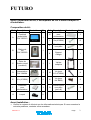
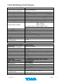
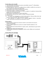
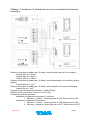
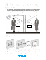
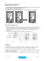
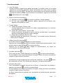
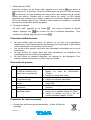
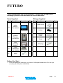
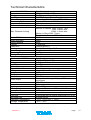
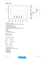
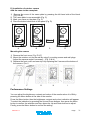
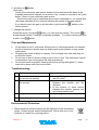
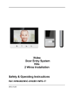
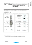
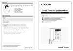
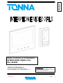
FRANCAIS
Mode d’emploi et d’installation
INTERPHONE VIDEO 2 fils
Réf. 683300
TONNA ELECTRONIQUE S.A.
36 avenue HOCHE 51100 REIMS FRANCE
E-Mail: [email protected] Web: www.tonna.com
Version 8.1
Recommandation
L’installation doit être réalisée par une
personne habilitée et possédant toutes les
connaissances nécessaires.
Page
1
FUTURO
Avant l’installation du kit, il est impératif de lire le mode d’emploi et
d’installation.
Composition du kit :
Ref
A
Description
Illustration
Combiné
audio/vidéo
Réf. 683310
Qté
Ref
H
1
Description
Rail DIN
pour
alimentation
Illustration
Qté
1
I
Vis(4*20BA)
6
J
Cheville pour
mur plein
6
K
Support
d’angle
1
Platine de
rue
Réf. 683320
1
C
Etrier de
fixation mural
(combiné)
1
L
Visière
antipluie
1
D
Alimentation
Réf. 684884
1
M
Vis (pour
K,3.9*32BA)
4
E
Vis (4*20BA)
4
N
Vis (pour
K,4*8KM)
2
F
Protection
pour
alimentation
1
O
Cheville pour
mur plein
(pour K)
4
G
Loquet
2
B
Avant Installation :
•
Vérifier le contenu du kit ainsi que les informations techniques. Si vous recontrez le
moindre problème, contacter votre revendeur.
Version 8.1
Page
2
Caractéristiques techniques :
Combiné vidéo Réf. 683310
Dimensions
(largeur x hauteur x épaisseur)
Poids
Tension d’alimentation
Consommation
Type de câblage
Extension
Transmission voix
Sonnerie d’appel
Distance Max. & câble
Video S/N Ratio
Audio S/N Ratio
Aspect Matériel
Ecran
Résolution
Extinction automatique
Réglage
Température de
fonctionnement
Température de stockage
Platine de rue Réf. 683320
Dimensions
(largeur x hauteur x épaisseur)
Poids
Tension d’alimentation
Consommation
Câblage
Caméra
TV system
Résolution
Sortie vidéo
Qualité capteur caméra
Iris
Vision de nuit
Angle de vue
Objectif
Serrure électrique compatible
Installation
Température de
fonctionnement
Température de stockage
Version 8.1
Spécifications
200 x150 x20 mm
0.54Kg
DC17V (alimentation externe au combiné)
En veille : 2W En fonctionnement : MAX 14W
2 fils
2 platines de rue et 2 combinés vidéo (5fils)
Half duplex
Son électronique (4 sonneries sélectionnables)
Combiné / Platine 25M : 0.5mm2
50M : 0.8mm2
100M : 1.0mm2
Combiné maître / esclave 20M: 1.0mm2
Serrure électrique / Platine 5M : 1.0mm2
50dB
40dB
Acryl
LCD 7’’ Couleur
480(H)X 3(RGB)X 234(V)
Veille : 20sec Auto off : 80sec
Volume sonnerie, volume voix montante, couleur, contr.
0 ~ 40
-20 ~ 60
Spécifications
90 x150 x 20 mm
0.4Kg
DC12V provenant du moniteur
Max 3W
Combiné : 2 fils Serrure électrique : 2 fils
CCD, couleur
PAL
380 TV Lignes
Composite vidéo signal 1Vp-p (75ohm)
270,000.pixels
Automatique
LED blanche
Diagonale:70˚ horizontale:51˚ verticale:41˚
3.7mm (objectif pin hole)
Max 12V 0.5A
En saillie
-1 0˚C ~ 50˚C (14°F ~ 122°F)
-20˚C ~ 60˚C
Page
3
Combiné vidéo
1. Ecran LCD
2. Décroché / raccroché (début / fin de communication) + Intercommunication
3. Ouverture de porte (12V pour serrure électrique)
4. Basculement camera (pour installation à 2 entrées)
5. Ouverture de porte (En mode veille, permet d’activer ou désactiver le mode silence)
6. Menu OSD (réglage luminosité, contraste, couleur)
7. Défilement bas (pour menu OSD)
8. Défilement haut (pour menu OSD)
9 Microphone
10. Volume de sonnerie
Platine de rue
1. Objectif de la caméra
2. LED pour vision de nuit
3. Haut parleur
4. Porte-étiquette
5. Bouton d’appel
6. Microphone
7. Support d’angle
8. Visière antipluie
Version 8.1
Page
4
Instructions de sécurité
1. Ne pas installer à proximité d’une source de radiation comme TV, Alimentation...
2. Ne pas démonter les modules.
3. Ne pas projeter de l’eau sur le combiné. Ne pas installer la platine de rue dans un
lieu contenant des moisissures importantes.
4. Ne pas obturer les orifices de ventilation du combiné.
5. Ne pas faire tomber ou choquer les modules.
6. Il est recommandé de déconnecter les fils du combine si le système n’est pas utilise
pendant une très longue période.
7. Ne pas placer à proximité d’une source de chaleur.
8. Ne pas placer à proximité de liquide ou d’objet contenant du liquide.
9. Ne pas couvrir.
10.
Ce produit est développé pour des climats modérés. Ne pas utiliser dans des
lieux à fort taux d’humidité, très poussiéreux ou sales.
11.
Pour démonter le combine du mur, éteindre l’appareil (bouton raccroché),
couper l’alimentation électrique puis déconnecter les fils.
Précautions
1. Ne pas installer la platine de rue face au soleil ou en direction d’une source
lumineuse importante.
2. Ne pas installer la platine de rue dans un endroit d’extrême salissure ou de
moisissure.
3. Ne pas installer à proximité d’élément oxydant, acide , ammoniaque ou gaz nocif et
dangereux
4. L’objectif de la camera doit rester propre.
7. Avant la mise en service de l’installation, vérifier que les câbles sont correctement
connectés.
Instructions de montage
+
Alimentation 17Vdc 1,5A
Version 8.1
Page
5
Câblage : 2 moniteurs / 2 platines de rue avec contact libre de potentiel
pour la commande de porte
Alimentation 17Vdc 1,5A
Platine de rue
Contact libre de potentiel
ON
OFF
Switch moniteur Maître
Platine de rue
ON
Contact libre de potentiel
OFF
Switch moniteur Esclave
Version 8.1
Page
6
Câblage : 2 moniteurs / 2 platines de rue avec commande d’une serrure
électrique
Alimentation 17Vdc 1,5A
Platine de rue
ON
Serrure électrique 12V 500mA
OFF
Switch moniteur Maître
Platine de rue
ON
OFF
Switch moniteur Esclave
Serrure électrique 12V 500mA
Distance et section de câble maxi. À utiliser entre la platine de rue et le moniteur :
- Jusqu’à 25m en 0,5mm2
- Jusqu’à 50m en 0,8mm2
- Jusqu’à 100m en 1,0mm2
Distance et section de câble maxi. À utiliser entre l’alimentation et le moniteur le plus
éloigné:
Jusqu’à 20m en 1 mm2
Distance et section de câble maxi. À utiliser entre la platine et la serrure électrique :
Jusqu’à 5m en 1 mm2
Puissance maxi de la serrure électrique : 12Vdc 500mA
Distance entre 2 moniteurs : 20m en 1mm2 (5 fils).
Position des switchs moniteurs :
- Installation comprenant uniquement 1 moniteur :
Moniteur 1 (maître) : Switch gauche en ON, Switch droit en ON
- Installation comprenant 2 moniteurs :
Moniteur 1 (maître) : Switch gauche en ON, Switch droit en ON
Moniteur 2 (esclave): Switch gauche en OFF, Switch droit en OFF
Version 8.1
Page
7
A) Raccordement
1. Connecter 2 fils de la platine de rue au moniteur (C- sur C2- et C+ sur C2+)
2. Prenez soin d’insérer le câble avec une force modérée et avec un outil adéquat.
B) Hauteur d’installation
1. Afin de favoriser l’accessibilité aux personnes handicapées, nous conseillons que
le bouton d’appel de la platine soit situé à une hauteur de 130cm par rapport au
niveau du sol (axe de la caméra à 137cm). Nous vous recommandons la même
hauteur pour les boutons du moniteur (partie basse du moniteur à 128cm).
137cm
128cm
C) Montage du moniteur
Fixer l’étrier sur le mur à l’aide des 4 vis. Positionner judicieusement l’étrier afin de
permettre au câble de passer à droite de l’étrier.
2. Positionner le moniteur sur l’étrier en le présentant par l’avant et vérouiller le en le
remontant.
3. Verrouiller l’étrier sur le moniteur à l’aide des 2 vis situées sous le moniteur.
Version 8.1
Page
8
1.
D) Installation de la platine de rue
Mettre un nom sur la platine.
1)
2)
3)
4)
Retirer la fenêtre du porte-étiquette en pressant à gauche de celui-ci. (Fig. A & B)
L’étiquette est maintenant accessible. (Fig. C)
Indiquer le nom sur l’étiquette (Fig. C)
Replacer la fenêtre dans sont logement en la ramenant vers l’avant (Fig. D)
Mark
A
B
Mark
C
D
Montage de la platine de rue
1) Démonter la façade en dévissant les deux vis situées sous la platine (Fig. E & F)
2) Fixer la platine de rue sur le mur à l’aide des 2 vis. Prenez soin de faire venir le
câble à l’endroit exact où se trouve le passage de câble dans la platine de rue
(Fig. G & H)
3) Refermer la façade avec les deux vis situées en dessous. (Fig. I)
E
F
G
H
I
Réglages
Vous pouvez ajuster la luminosité, le contraste et la couleur du moniteur quand le
moniteur est alimenté et en appuyant sur le bouton MENU du moniteur (●).
Appuyer sur le bouton MENU (●). Pour sélectionner le réglage à modifier, appuyer sur
Flèche bas ou Flèche haut.
Appuyer sur Menu pour effectuer un réglage et les flèches pour modifier le réglage.
Version 8.1
Page
9
Fonctionnement
1. Lors d’un appel :
Quand le bouton d’appel de la platine est pressé, le moniteur sonne et le visiteur
apparaît sur le moniteur. Quand le visiteur est identifié et si vous voulez lui parler,
appuyer sur le bouton
. Le temps de communication est de 80secondes, après
ce temps le moniteur s’éteint. Pour ré-activer la conversation, appuyer sur le bouton
et décrocher par le bouton
.
2. Activer la fonction surveillance :
a) Appuyer sur le bouton
pour activer le moniteur, l’image apparaît.
b) Si vous avez installé une deuxième platine, appuyez sur ce bouton pour
basculer d’une platine à l’autre.
3. Temps utilisés :
a) Temps de sonnerie : Environ 20s
L’image apparaît dès la sonnerie et s’éteint automatiquement si le moniteur
n’est pas décroché.
b) Temps de communication : Environ 80s
Quand le moniteur est appelé et que le moniteur est décroché, il se passera
environ 80 seconds avant que l’écran s’éteigne.
c) Temps de surveillance: Environ 40s
Quand la platine est activée par le moniteur, il se passera environ 40seconds
avant qu’il ne s’éteigne.
4. Utiliser la fonction intercom
:
La fonction intercom permet d’appeler un autre moniteur.
Appuyer sur le bouton
du premier moniteur, le deuxième moniteur sonne. Vous
pouvez parler en appuyant sur
du second moniteur.
Appuyer sur le bouton
pour couper la communication. Le temps de
communication est fixé à 80 seconds.
5. Ouverture de porte
:
Pour ouvrir la porte, il suffit d’appuyer sur le bouton
lors de la communication.
Si vous désirez ouvrir la porte en dehors d’un appel, utiliser la fonction surveillance
(chapitre 2) pour activer le moniteur.
La platine de rue est équipée de deux sorties de commande ; Le bouton
permet
de commander la Sortie 12V 500mA pour alimenter une serrure électrique.
6. Ouverture de portail :
Pour commander un portail connecté sur la Sortie « Contact libre de potentiel »,
appuyer sur le bouton
lors de la communication.
Si vous désirez ouvrir la porte en dehors d’un appel, utiliser la fonction surveillance
(chapitre 2) pour activer le moniteur.
La Sortie contact libre de potentiel pour commander un portail motorisé sans ajout
de matériel.
Version 8.1
Page
10
7. Mode Silence On/Off:
Quand le moniteur est en mode veille, appuyer sur le bouton
pour activer le
mode silence sur le moniteur. Quand le mode silence est activé, la LED du bouton
va s’illuminer en violet (mélange de rouge et bleu) pour indiquer que la fonction
silence est activée. Pendant que le mode silence est activé, la LED violette
clignotera pour indiquer qu’un visiteur a appuyé sur le bouton d’appel de la platine
de rue et n’émettra pas de son. Quand le mode silence est désactivé, l’ensemble
des boutons devient bleu durant les appels.
8. Changer la mélodie
En mode veille, appuyez sur la touche
utilisée. Appuyez sur
, vous pouvez entendre la mélodie
pour choisir une des 4 mélodies disponibles.
confirmer la mélodie, appuyez sur le bouton
Pour
.
Précaution et Maintenance
Ne pas installer près de source de chaleur ou de froid. Les températures
importantes ou très basses peuvent endommager les composants et peut altérer
certains plastiques ou causer des mal fonctions.
Les courts-circuits peuvent provoquer des dommages irréversibles sur le circuit
électronique.
Ne pas stocker ou utiliser dans des lieux poussiéreux ou insalubres. Les
composants peuvent s’altérer plus rapidement.
Ne pas utiliser de produits chimiques, de solvants ou de détergents. Pour
nettoyer, passer uniquement un chiffon très peu humide.
Recherche de pannes
No
Problème
1
Pas de sonnerie, pas d’image Vérifier l’alimentation secteur ainsi que la
(la LED à l’intérieur de la
tension de sortie de l’alimentation
platine de rue est éteinte)
(17Vdc).
Vérifier la polarité des câbles
L’alimentation est ok mais il
Vérifier la polarité du câble platine.
n’y a pas d’image
Vérifier la continuité des câbles.
L’image est trop claire ou trop Vérifier les réglages du moniteur par le
foncée
menu OSD.
La sonnerie est trop faible ou Vérifier le réglage de sonnerie du
inexistante
moniteur
Image qui défile ou de
Vérifier la tension sur les 2 fils de la
mauvaise qualité
platine de rue pendant l’appel (12,5Vdc)
Vérifier la tension sur les 2 fils du
moniteur pendant l’appel (17VDC)
2
3
4
5
Point à vérifier
Protection de l’environnement
•
Ne pas jeter dans une poubelle domestique. Utiliser la filière du
recyclage.
Version 8.1
Page
11
Version 8.1
Page
12
ENGLISH
Safety & Operating Instructions
Réf. 683300 Video DoorPhone
TONNA ELECTRONIQUE S.A.
36 avenue HOCHE 51100 REIMS FRANCE
Phone +33 (0)3 26 05 50 17 Fax +33 (0)3 26 05 28 92
E-Mail [email protected] Web: www.tonna.com
Version 8.1
We recommend
This equipment is installed by a
Competent Electrician, Security or
Communications Engineer.
Page
13
FUTURO
These instructions are for your safety. Please read through them
thoroughly before use and retain for future reference.
Parts Supplied
Ref
A
Description
Indoor
Monitor
Réf. 683310
Fittings Supplied
Illustration
Qty
Description
Illustration
Qty
F
Power cover
1
G
Locker
2
H
Bracket
Holder
1
I
Screw
6
J
Wall plug
6
1
Outdoor
Camera
Réf.683320
1
C
Wall
mounting
bracket
1
D
Power
Transformer
Réf. 684884
1
E
screw
4
B
Ref
Before You Start
•
Check the pack and make sure you have all of the part listed above You can join
us hotline at 0033 (0) 3 26 05 28 94.
Version 8.1
Page
14
Technical Characteristics
Indoor Unit( 683310)
Dimensions
Weight
Input Power
Power Consumption
Connecting System
Voice transmission
Call sound
Max. Distance & wiring
Video S/N Ratio
Audio S/N Ratio
Aspect Material
Display
Resolution
Monitor on time
Users Control
Operating Temperature
Storage Temperature
Outdoor Unit 683320
Dimensions
Weight
Input Power
Power Consumption
Aspect Material
Wiring
Image sensor
TV system
Resolution
Video output
No. of pixels
Iris
Lighting
Viewing Angle
Lens
Min. Illumination
Door lock
Mounting type
Operating Temperature
Storage Temperature
Version 8.1
Specifications
200[W] x150 [H] x20 [D] mm
0.54Kg
DC17V (External Power Supply)
Idle mode : 2W Operating : MAX 14W
2 wires; 2 Cameras, 2 Monitors
Half duplex two way communication
Chime sound
Monitor to Camera 25M : 0,5mm2 wire
50M : 0.8mm2 wire
100M : 1.0mm2 wire
Master to Slave 20M: 1.0mm2
Door Lock to Camera 20M : 1.0mm2 wire
50dB
40dB
Acryl
7 inch LCD
1440(H)X234(V)
Stanby : 40sec Auto off : 80sec
Ring sound volume;Receive sound volume
0 ~ 40
-20 ~ 60
Specifications
90[W] x150[H] x 20 [D] mm
0.4Kg
DC12V from monitor
Max 3W
Aluminium
Monitor:2wires Door lock:2Wires
CCD, colour
PAL
380 TV Lines
Composite video signal 1Vp-p at 75ohm
terminated
270,000.pixels
Electronic auto iris
White LED
Diagonal:70˚ horizontal:51˚ vertical:41˚
3.7mm pin hole lens
1Lux
2 terminals with DC power output max 12V 0.5A
Surface mount
-1 0˚C ~ 50˚C(14°F ~ 122°F)
-20˚C ~ 60˚C
Page
15
Indoor unit
1. Monitor screen
2. Talk on/Talk off (Monitor off) and Intercom
3. Door Open (12V )
4. Camera 1/ Camera 2
5. Gate Open ( Dry contact)
6. Menu Select( Brightness, Contrast, Color )
7. Down
8. Up
9 Microphone
10. Ring Sound volume
Outdoor unit
1. Camera lens
2. White LEDs for night vision
3. Speaker
4. Name Plate
5. Call Button
6. Microphone
Version 8.1
Page
16
Safety Instructions
2. Do not install near other electronic equipment such as computers, TV, video
recorder as this may cause radiated interference to the unit.
2. Do not disassemble the unit.
3. Do not spray water on the indoor unit. Do not keep the outdoor unit where it will be
exposed to extreme moisture.
4. Do not overload mains wall outlets or extension cords.
5. Do not drop or shock the unit.
6. Remove the power cord from the wall socket when unit is not used for long periods.
7. Do not place any naked flames (e.g. lighted candles) on the apparatus.
8. Do not place objects filled with water (e.g. vases) on the apparatus.
9. Do not cover the ventilation holes with clothing, paper, curtains etc.
10.
This apparatus is designed for moderate climates. Do not use in high humidity,
dusty or dirty areas.
11.
To disconnect or isolate the unit, switch off at the socket or remove plug from
wall socket. Please ensure the plug and socket is easily accessible.
Warnings
1. Do not install the outdoor unit where it will be exposed to direct sunlight or any
strong reflected light. Avoid extremely bright locations for the indoor unit as the
monitor screen image will be adversely affected.
2. Do not install the outdoor unit where it will be subjected to extremes of dust or
moisture.
3. Do not install the outdoor unit where it will be exposed to rain.
4. Do not install near acid oxides, ammonia, or any harmful gas (it might cause
malfunction).
5. Do not install the outdoor unit in a location where the lens filter is likely to get
scratched or very dusty.
6. Check cables are connected correctly and camera unit is firmly installed.
Assembly instructions
17Vdc 1,5A
Version 8.1
+
Page
17
Wiring diagram : 2 entrances + 2 monitor and Dry contact
Power supply 17Vdc 1,5A
Outdoor Station
ON
OFF
Switch MASTER
Outdoor Station
ON
OFF
Switch SLAVE
Version 8.1
Page
18
Wiring diagram : 2 entrances + 2 monitor and Electric lock
Power supply 17Vdc 1,5A
Outdoor Station
ON
Electric lock 12V 500mA
OFF
Switch MASTER
Outdoor Station
ON
OFF
Switch SLAVE
Electric lock 12V 500mA
Version 8.1
Page
19
A) Cable connection
1. Connect the monitor to the camera with the cable according to the wiring diagram.
2. Carefully insert the wires to the terminal by pressing down the terminal flap with
any small tool taking care that the 2 bare wires do not touch.
B) Installation height
1. Recommended installation height is approximately 140cm for monitor unit and
150cm for outdoor camera.
C) Installation of indoor monitor
1.
2.
3.
Fix the wall mounting bracket in the best place by using 4 screws and plugs.
Carefully place the indoor monitor against the bracket and gently push down the
monitor so that the pins on the bracket engage in the slots on the rear of the
monitor.
Secure the assembly with the 2 screws.
Version 8.1
Page
20
D) Installation of outdoor camera
Add the name to the nameplate
1) Remove the cover of the name plate by pressing the left hand side of the block.
(Fig. A & B)
2) The name plate is now accessible (Fig. C)
3) Mark your name on the plate (Fig. C)
4) Place the button block back to the panel (Fig. D)
Mark
A
B
Mark
C
D
Mounting the camera
1) Remove the front cover (Fig. E & F)
2) Mount the outdoor unit on the wall by using 2 mounting screws and wall plugs.
Adjust the camera angle if necessary. (Fig. G & H)
3) Replace the front cover and security it by replacing the 2 screws at the bottom of
the camera. (Fig. I)
E
F
G
H
I
Performance Settings
You can adjust the brightness, contrast and colour of the monitor when it is ON by
pressing the Menu button at the side of the monitor.
Press the Menu button then the brightness, contract and colour indication will appear.
To select the indication by pressing the Up and Down buttons, then press the Menu
button to confirm the selection and then press the Up and Down buttons to adjust.
Finally, press the Menu button to confirm the setting.
Version 8.1
Page
21
Operating Instructions
1. Activation of units
When the call button on the outside camera unit is pressed, the indoor unit chime
rings and the visitor’s picture will appear on the indoor monitor. After the visitor is
visually identified, and you wish to talk with the visitor, touch the
button. The
unit will remain activated for approximately 80 seconds before it automatically shuts
off. To re-activate for continued conversation, touch the
the
button.
button and then touch
2. Activation of outside unit from monitor unit
a) Touch the
button of the indoor unit at any time and the outdoor camera will
be activated and show the outside view.
b) If you have installed two cameras, touch this button to change from camera
one to another.
3. Working time
a) Call time: Approximately 40 seconds
The picture terminates automatically if indoor unit is not answered within
approximately 40 seconds after the call button of the outdoor camera unit is
touched.
b) Talk time: Approximately 80 seconds
When monitor unit is called by the outdoor unit and the monitor is answered,
there is approximately 80 seconds of time available before the unit
automatically shuts off.
c) Monitor time: Approximately 40 seconds
When outside camera is activated from the inside, there is approximately 40
seconds of viewing time before the unit automatically shuts off.
4. Activation of “Intercom” button
An intercom calling can be started by any indoor monitor when it is on standby
mode.
on one indoor monitor is touched, this will ring all
When the intercom button
monitors in a system,you can talk with the one calling monitor by touching the
button on the second monitor, touch
for shutting off. There is approximately 80
seconds of time before the unit automatically shuts off.
5. Activation of
button
Door open:
If an electrical lock or door strike is added to the installation, connect it to the
terminals at the back of the roadside panel.
This function can only be used when the screen is switched on. It is normal that
the image switches off one moment following the control of the door open.
If you want to open the door to let the caller in, just touch the
indoor monitor.
Version 8.1
button on the
Page
22
6. Activation of
button
Gate open:
Connect the automatic gate opener directly to the terminals at the back of the
roadside panel which supplies a current-free “dry” contact to connect to the “push
button” control of your automatic gate opener.
This function can only be used when the screen is switched on. It is normal that
the image switches off one moment following the control of the gate opener.
If you want to open the gate to let the caller in,just touch the
indoor monitor.
button on the
7. Change the melody
At standby mode, touch the
button, you can hear the melody. Then touch
to
choose target melody. There are 4 melodies available. To confirm melody you have
chosen, touch
button.
Care and Maintenance
Do not store in hot or cold areas. Extreme hot or cold temperatures can shorten
the life of electronic devices and can distort/melt certain plastics or may cause
malfunction.
Dropping can result in failure to operate. Circuit boards can crack and may not
survive the impact.
Do not use or store in areas of high levels of dirt or dust. The electronics may be
contaminated. Any moving parts will wear prematurely.
Do not use harsh chemicals, cleaning solvents or strong detergents. To clean,
wipe with a damp cloth from time to time.
Troubleshooting
No Problem
Check point
1
3
The picture is too dark or white
Is the AC plug firmly inserted into
the AC outlet?
Is the cable firmly connected
between the monitor and the
camera?
Is the polarity of wires correct
between the outdoor camera unit
and indoor monitor unit?
Adjust brightness control
4
Chime sound is too low
Adjust the volume control
2
No power
(no picture on monitor)
Power is on, but no picture on
the monitor
Environmental Protection
•
Waste electrical products should not be disposed of with household
waste. Please recycle where facilities exist. Check with your Local
Authority or retailer for recycling advice.
Version 8.1
Page
23