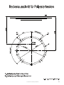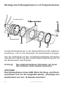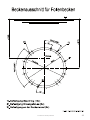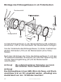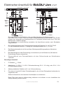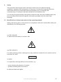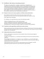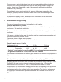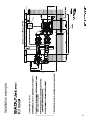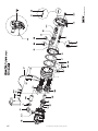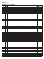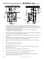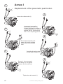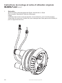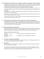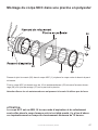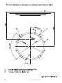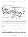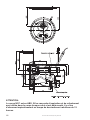
1
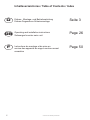
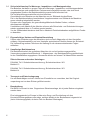
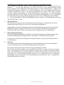
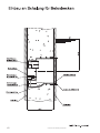
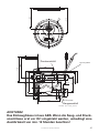
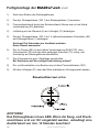
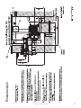
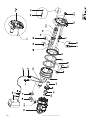
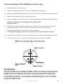
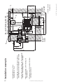
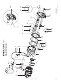
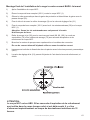
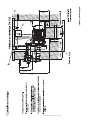
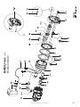
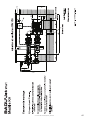
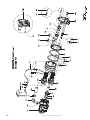
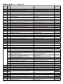
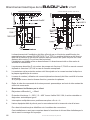
07.07.2010 TB-b bta badu jet smart.indd
1
Inhaltsverzeichniss / Table of Contents / Index
D
GB
F
2
Einbau-, Montage- und Betriebsanleitung
Einbau-Gegenstrom-Schwimmanlage
Seite 3
Operating and installation instructions
Submerged counter swim unit
Page 26
Instructions de montage et de mise en
service des appareils de nage à contre-courant
encastrée
Page 50
07.07.2010 TB-b bta badu jet smart.indd
Original Montage- und Betriebsanleitung
BADU®Jet smart
1.
Allgemeines
Speck-Pumpen Verkaufsgesellschaft GmbH, Neunkirchen a. Sand
Ursprungsland: Bundesrepublik Deutschland
Einsatzbereich:
Zum Wandeinbau in alle Schwimmbecken-Ausfürungen, als Attraktion zur Fitneß, als
Wellen-oder Luftperlbad, Unterwassermassage (nach ärztlichem Rat), Schwimmen ohne
Wende
07.07.2010 TB-b bta badu jet smart.indd
3
2.
Sicherheit
Diese Betriebsanleitung enthält grundlegende Hinweise, die bei Aufstellung, Betrieb und
Wartung zu beachten sind. Daher ist diese Betriebsanleitung unbedingt vor Montage und
Inbetriebnahme vom Monteur sowie dem zuständigen Fachpersonal/Betreiber zu lesen
und muss ständig am Einsatzort der Maschine/Anlage verfügbar sein.
Es sind nicht nur die unter diesem Hauptpunkt Sicherheit aufgeführten, allgemeinen Sicherheitshinweise zu beachten, sondern auch die unter den anderen Hauptpunkten eingefügten, speziellen Sicherheitshinweise, so z. B. für den privaten Gebrauch.
2.1 Kennzeichnung von Hinweisen in der Betriebsanleitung
Die in dieser Betriebsanleitung enthaltenen Sicherheitshinweise, die bei
Nichtbeachtung Gefährdungen für Personen hervorrufen können, sind mit
allgemeinen Gefahrensymbolen
Sicherheitszeichen nach DIN 4844 - W 9
bei Warnung vor elektrischer Spannung mit
ACHTUNG
eingefügt.
Direkt an der Maschine angebrachte Hinweise wie z. B.
- Drehrichtungspfeil
- Kennzeichen für Fluidanschlüsse
müssen unbedingt beachtet und in vollständig lesbarem Zustand gehalten werden.
4
07.07.2010 TB-b bta badu jet smart.indd
2.2 Personalqualifikation und -schulung
Das Personal für Bedienung, Wartung, Inspektion und Montage muss die
entsprechende Qualifikation für diese Arbeiten aufweisen.
Verantwortungsbereich, Zuständigkeit und die Überwachung des Personals müssen durch
den Betreiber genau geregelt sein. Liegen bei dem Personal nicht die notwendigen
Kenntnisse vor, so ist dieses zu schulen und zu unterweisen. Dies kann, falls erforderlich, im
Auftrag des Betreibers der Maschine durch den Hersteller/Lieferanten erfolgen.
Weiterhin ist durch den Betreiber sicherzustellen, dass der Inhalt der Betriebsanleitung
durch das Personal voll verstanden wird.
2.3 Gefahren bei Nichtbeachtung der Sicherheitshinweise
Die Nichtbeachtung der Sicherheitshinweise kann sowohl eine Gefährdung für
Personen als auch für Umwelt und Maschine zur Folge haben. Die Nichtbeachtung der Sicherheitshinweise kann zum Verlust jeglicher Schadenersatzansprüche führen.
Im einzelnen kann Nichtbeachtung beispielsweise folgende Gefährdungen
nach sich ziehen:
- Versagen wichtiger Funktionen der Maschine/Anlage
- Versagen vorgeschriebener
- Gefährdungen von Personen durch elektrische, mechanische und chemische
Einwirkungen
- Gefährdung der Umwelt durch Leckage von gefährlichen Stoffen
- Beschädigung von Einrichtungen und Bauwerken
2.4 Sicherheitsbewußtes Arbeiten
Die in der Betriebsanleitung aufgeführten Sicherheitshinweise, die be stehenden nationalen
Vorschriften zur Unfallverhütung sowie eventuelle interne Arbeits-, Betriebs- und
Sicherheitsvorschriften des Betreibers sind zu beachten.
2.5 Allgemeine Sicherheitshinweise für den Betreiber/Bediener
Führen heiße oder kalte Maschinenteile zu Gefahren, müssen diese Teile bauseitig gegen
Berührung gesichert sein.
Berührungsschutz für sich bewegende Teile (z. B. Kupplung) darf bei sich in Betrieb befind
licher Maschine nicht entfernt werden.
Leckagen (z. B. der Wellendichtung) gefährlicher Fördergüter (z. B. explosiv, giftig, heiß)
müssen so abgeführt werden, dass keine Gefährdung für Personen und die Umwelt entsteht.
Gesetzliche Bestimmungen sind einzuhalten.
Gefährdungen durch elektrische Energie sind auszuschließen (Einzelheiten
hierzu siehe z. B. in den Vorschriften des VDE und der örtlichen Energieversorgungsunternehmen).
Es ist auf eine ordnungsgemäße Nutzung durch die Badegäste zu achten.
Die Gegenstrom-Schwimmanlage ist nur zum Gegenschwimmen und Massieren geeignet.
Bei anderer Nutzung oder vom Hersteller nicht genehmigten Umbauten erlischt jeglicher
Garantie- und Haftungsanschpruch.
Es ist darauf zu achten, dass die Wassertemperatur 35°C nicht übersteigt!
07.07.2010 TB-b bta badu jet smart.indd
5
2.6 Sicherheitshinweise für Wartungs-, Inspektions- und Montagearbeiten
Der Betreiber hat dafür zu sorgen, dass alle Wartungs-, Inspektions- und Montagearbeiten
von autorisiertem und qualifiziertem Fachpersonal ausgeführt werden, das sich durch
eingehendes Studium der Betriebsanleitung ausreichend informiert hat.
Die Unfallverhütungsvorschriften sind zu beachten.
Grundsätzlich sind Arbeiten an der Maschine nur im Stillstand durchzuführen.
Die in der Betriebsanleitung beschriebene Vorgehensweise zum Stillstand der Maschine
muss unbedingt eingehalten werden.
Pumpen oder -aggregate, die gesundheitsgefährdende Medien fördern, müssen
dekontaminiert werden.
Unmittelbar nach Abschluß der Arbeiten müssen alle Sicherheits- und Schutzeinrichtungen
wieder angebracht bzw. in Funktion gesetzt werden.
Vor der Wiederinbetriebnahme sind die im Abschnitt Erstinbetriebnahme aufgeführten Punkte
zu beachten.
2.7 Eigenmächtiger Umbau und Ersatzteilherstellung
Umbau oder Veränderungen der Maschine sind nur nach Absprache mit dem Hersteller
zulässig. Originalersatzteile und vom Hersteller autorisiertes Zubehör dienen der Sicherheit.
Die Verwendung anderer Teile kann die Haftung für die daraus entstehenden Folgen
aufheben.
2.8 Unzulässige Betriebsweisen
Die Betriebssicherheit der gelieferten Maschine ist nur bei bestimmungsgemäßer
Verwendung entsprechend Abschnitt 1 - Allgemeines - der Betriebsanleitung gewährleistet.
In den Datenblättern angegebene Grenzwerte dürfen auf keinen Fall überschritten werden.
Zitierte Normen und andere Unterlagen
DIN 4844 Teil 1 Sicherheitskennzeichnung; Sicherheitszeichen W 8
Beiblatt 13
DIN 4844 Teil 1 Sicherheitskennzeichnung; Sicherheitszeichen W 9
Beiblatt 14
3.
Transport und Zwischenlagerung
Um ein Beschädigen und den Verlust von Einzelteilen zu vermeiden, darf die Originalverpackung erst vor dem Einbau geöffnet werden.
4.
Beschreibung
Die BADU Jet smart ist eine Gegenstrom-Schwimmanlage, die in jedes Becken eingebaut
werden kann.
Eine leistungsstarke Jet-Pumpe ist über eine Saug- und Druckleitung mit dem
Kunststoff-Einbaugehäuse verbunden, welches bündig in der Beckenwand eingesetzt ist
(keine Verletzungsgefahr, da keine Teile ins Becken hineinragen).
6
07.07.2010 TB-b bta badu jet smart.indd
Über den umlaufenden Ringkanal im Gehäuse wird das Badewasser mit geringer
Strömung von der Jet-Pumpe angesaugt und mit hohem Druck über die Düse in das
Schwimmbecken zurückgefördert.
Die Ein- und Ausschaltung der Jet-Pumpe erfolgt über einen Pneumatik-Taster, der im
Düsengehäuse eingebaut ist.
Über die regelbare Düse kann der Förderstrom und damit die Wirkung der Gegenstromanlage individuell eingeregelt werden. Mit einer Luftregulierung kann dem Düsenstrom
wahlweise Luft beigemischt werden.
Als Option sind eine aufsteckbare Massagedüse, ein Massageschlauch, ein Massageschlauch mit Pulsator und ein aufsteckbarer Pulsator im Lieferprogramm.
5.
Aufstellung, Einbau, Installation (Planung)
Schaltkasten und Pumpe sind in einem trockenen Raum zu installieren.
Es ist unbedingt ein Bodenablauf vorzusehen.
Der Abstand zwischen Becken und Schaltkasten darf max. 10 m betragen, um ein einwandfreies funktionieren des Pneumatiktasters zu gewährleisten.
Der Pneumatikschlauch ist in einem Schutzschlauch zu verlegen, damit er später ohne
weiteres ausgetauscht werden kann.
Wird die Pumpe weiter entfernt aufgestellt, muss die Rohrleitungsdimension so angepasst werden,
dass eine nahezu verlustfreie Strömung gewährleistet ist.
Möglichst Bögen anstatt Winkel verwenden!
Ansonsten ist die Wirkung der Gegenstrom-Schwimmanlage geringer.
Sollvolumenstrom ca. 58 m³/h
Rohrleitungslänge bis
Saugleitung
Druckleitung
5m
d 140
d 140
5-7,5 m
d 140
d 140
7,5-10 m
d 140
d 140
Achtung! Das Einbaugehäuse ist aus ABS. Wenn die Saug- und Druckanschlüsse erst vor Ort eingeklebt werden, unbedingt eine Aushärtezeit von min. 12 Stunden
beachten!
Die Gesamtsalzkonzentration im Schwimmbadwasser dar f 0,5% (entspr. 5g/l) nicht
übersteigen.
07.07.2010 TB-b bta badu jet smart.indd
7
Der Elektroanschluß darf nur von einem Fachmann ausgeführt werden!
Es ist darauf zu achten, dass in der Elektroinstallation eine Trennvorrichtung vorgesehen
ist, die das Abtrennen vom Netz mit mind. 3 mm Kontaktabstand jedes
Poles gestattet. Die Gegenstrom-Schwimmanlage ist nach Schutzklasse 1 gebaut. Die
Umgebungstemperatur darf max. 40° nicht übersteigen. Die in den Gegenstrom-Schwimmanlagen ein ge bau ten Dreh- und Wechselstrommotore werden über einen ent sprechenden Motorschutzschalter im Originalschaltkasten abgesichert. Vor Inbetriebnahme
ist der Einstellwert mit dem Wert, der auf dem Typenschild angegeben ist, zu vergleichen.
Die elektrische Anlage ist gemäß der gültigen Norm mit einem Fehlerstromschutzschalter
IΔN ≤ 30 mA abzusichern. Das Anschlußkabel zwischen Pumpe und Schaltkasten sollte vom
Typ H07 RNF 4G 1,5 sein.
6.
Inbetriebnahme
Bei Drehstrom ist durch kurzes Einschalten die Drehrichtung zu kontrollieren. Sie muss
entsprechend dem Pfeil sein, der auf der Lüfterhaube aufgeklebt ist.
Insbesondere ist diese Drehrichtungskontrolle wichtig bei Drehstrommotoren, da hier die
Möglichkeit besteht, dass die Pumpe auch in der verkehrten Drehrichtung laufen kann.
Ist dies der Fall, sind 2 Phasen zu vertauschen um diese Kontrolle zu wiederholen.
7.
8.
Wartung/Instandhaltung
Besteht Frostgefahr während des Winters ist der Wasserspiegel im Schwimmbecken bis
Unterkante Einbaugehäuse abzusenken, damit Saug- und Druckleitung leerlaufen.
Es ist sinnvoll, während des Winters die Pumpe abzubauen und in einem trockenen Raum
zu überwintern.
Störung
Die Jet-Pumpe hat eine Gleitringdichtung zur Wellenabdichtung. Wenn laufend Wasser
unter der Pumpe austritt, ist die Gleitringdichtung auszuwechseln.
Bei der Demontage der Pumpe sollte wie folgt vorgegangen werden:
Die Pumpe ist auszuschalten und zuverlässig vom Netz zu trennen. Der Austausch
sollte grundsätzlich nur von einem Fachmann vorgenommen werden. Die Pumpe, welche
über eine Verschraubung mit der Saugleitung und einem Gummiwinkel mit der Druckleitung
verbunden ist, vom Einbaugehäuse trennen und entsprechend der se pa ra ten
Montageanleitung demontieren, die Gleitringdichtung austauschen und in umgekehrter
Reihenfolge wieder montieren.
8
07.07.2010 TB-b bta badu jet smart.indd
07.07.2010 TB-b bta badu jet smart.indd
9
10
07.07.2010 TB-b bta badu jet smart.indd
07.07.2010 TB-b bta badu jet smart.indd
11
Montage des Einbaugehäuses in ein Polyesterbecken
Druckanschluß
Sauganschluß
Auf das Einbaugehäuse (1) die Noppendichtung (26) aufsetzen,
eindrücken und an die Rückseite der Beckenwand anlegen.
Von der Vorderseite mit den 10 selbstschneidenden Schrauben
(52) über den Spannring (28) und der Spannringdichtung (27) mit
der Beckenwand verschrauben.
Achtung!
Die selbstschneidenen Schrauben nur handfest anziehen. Keine Gewalt anwenden!
ACHTUNG!
Das Einbaughäuse ist aus ABS. Wenn die Saug- und Druckanschlüsse erst vor Ort eingeklebt werden, unbedingt eine
Aushärtezeit von min. 12 Stunden beachten!
12
07.07.2010 TB-b bta badu jet smart.indd
07.07.2010 TB-b bta badu jet smart.indd
13
Montage des Einbaugehäuses in ein Folienbecken
Druckanschluß
Sauganschluß
Auf das Einbaugehäuse (1) die Noppendichtung (26) aufsetzen,
eindrücken und an die Rückseite der Beckenwand anlegen.
Von der Vorderseite das Einbaugehäuse (1) mit den 2 selbschneidenden Schrauben (103) an der Beckenwand (ohne Folie)
fixieren.
Nach dem Einbringen der Folie das Einbaugehäuse (1) mit den
10 selbstschneidenden Schrauben (52) über den Spannring (28)
und der Spannringdichtung (27) mit der Beckenwand
verschrauben.
Achtung!
Die selbstschneidenen Schrauben nur handfest anziehen. Keine Gewalt anwenden!
Achtung!
Das Einbaughäuse ist aus ABS. Wenn die Saug- und Druckanschlüsse erst vor Ort eingeklebt werden, unbedingt eine
Aushärtezeit von min. 12 Stunden beachten!
14
07.07.2010 TB-b bta badu jet smart.indd
~310
Ø3
40
~250
~250
Druckanschluß
Nicht eingeklebt!
Ø243
Ø277
Ø74,9
Ø63
G2
125
ca. 23
185
Ø74,9
TK Ø255
~301
Ø63
~310
160
48
240
Nicht eingeklebt!
Sauganschluß
28.04.2005 TB-b mz smart_rund.fh11
ACHTUNG!
Das Einbaughäuse ist aus ABS. Wenn die Saug- und Druckanschlüsse erst vor Ort eingeklebt werden, unbedingt eine
Aushärtezeit von min. 12 Stunden beachten!
07.07.2010 TB-b bta badu jet smart.indd
15
Fertigmontage der BADU®Jet smart
1)
Nach dem Einbau des Einbaugehäuses
2)
Das kpl. Düsengehäuse (102.1) am Einbaugehäuse (1) ansetzen.
3)
Pneumatikschlauch durch den Schutzschlauch führen und mit der Kabel
verschraubung (20) abdichten.
4)
Luftleitung mit der Klemme (8) am Luftregler (21) befestigen.
5)
Das kpl. Düsengehäuse (102.1) mit 4 selbstschneidenden Schrauben (95)
am Einbaugehäuse (1) befestigen.
Achtung! Die Schrauben nur handfest anziehen.
Keine Gewalt anwenden!
6)
Die Jet Pumpe (92) mit der halben Verschraubung (98,99,100), dem
Gummiwinkel (79) und den dazu gehörigen Klemmen (75), saug- und
druckseitig am Einbaugehäuse anschließen.
7)
Den Pumpenmotor gem. Schaltplan anschließen.
Bei Drehstrom auf die richtige Drehrichtung achten!!
8)
Ein- und Ausschalten vom Becken aus mit dem Pneumatiktaster (38/1)
9)
Mit dem Luftregler (21) kann der Düse wahlweise Luft beigemischt werden.
ACHTUNG!
Das Einbaughäuse ist aus ABS. Wenn die Saug- und Druckanschlüsse erst vor Ort eingeklebt werden, unbedingt eine
Aushärtezeit von min. 12 Stunden beachten!
16
07.07.2010 TB-b bta badu jet smart.indd
Einbaubeispiel
07.07.2010 TB-b bta badu jet smart.indd
17
18
07.07.2010 TB-b bta badu jet smart.indd
BADU®Jet smart
Ausführung standard / model standard
Teil
Part
St.
Qty.
Benennung
Artikel-Nr.
Vormontagesatz
Description
Article no.
Pre-assembly kit
Jet-housing, WG 2350011-1
Screwed cable gland, M 20 x 1,5,
black
Union nut 2 3/4"
Flange sleeve, 63 mm
O-ring, 67 x 4 mm, Perb.
Nonreturn valve, D 1/2"
2300.101.001
2300.200.010
2300.200.020
2300.200.030
5879. 006.035
5879.825.520
2300.101.130
2300.101.120
1
20
1
1
98
99
100
101
1
1
1
1
Einbaugehäuse, WG 2350011-1
Kabelverschraubung, M 20 x 1,5,
schwarz
PVC-Überwurfmutter 2 3/4"
Bundbuchse, 63 mm
O-Ring, 67 x 4 mm, Perb.
Rückflussverhinderer, D 1/2"
26
27
28
52
103
105
106
1
1
1
10
2
1
1
Noppendichtung
Spannringdichtung
Spannring
Ejot-PT-Schraube, KB 60 x 35, A 2
Senkkopfschraube, 5,5 x 19, A 4
Saugrohr, 63 x 3 mm, WG2350013, Länge 7,6 cm
Druckrohr, 63 x 3 mm, WG2350012, Länge 10,4cm
Gasket with knobs
Gasket for clamping ring
Clambing ring
Ejot-PT-screw, KB 60 x 35, A 2
Countersunk head screw, 5,5 x 19, A4
Suction pipe,63x3 mm, WG2350013 length 7,6cm
Pressure pipe, 63x3 mm, WG2350012, length 10,4cm
Fertigmontagesatz
Final assemby kit
5882.502.015
5863.374.081
5863.390.064
2923.641.270
5030.000.105
102.1
10
21
38/1
46
47
1
3
1
1
1
10
Düsengehäuse kpl., bestehend aus:
Linsenblechschraube, 2,9 x 9,5, A 2, Form F
Luftregulierung kpl.
Pneumatiktaster kpl.
Ein-Ohr-Klemme
mtr. PVC-Schlauch, 4 x 1,5 mm, glasklar,
ohne Gewebe
Nozzle housing cpl., consisting of:
Pan-head tapping screw, 2,9 x 9,5, A 2, form F
Air control, cpl.
Pneumatik push botton cpl.
Hose clamp
mtr. PVC hose, 4 x 1,5 mm, clear
2300.202.000
5879.812.996
2300.407.000
2300.401.700
2302.001.046
2302.001.047
54/1
55
59
62
68
102
1
1
1
1
3
1
regelbare Kugeldüse, 40 mm
O-Ring, 73 x 2,5 mm
Düsenrohr, WG2350015
O-Ring, 59 x 2,5 mm
Ejot-PT-Schraube, KB 60 x 22, A 2
Düsengehäuse, WG2350014-1
Adjustable nozzle, 40 mm
O-ring, 73 x 2,5 mm
Blast pipe, WG2350015
O-ring, 59 x 2,5 mm
Ejot-PT-screw, KB 60 x 22, A 2
Düsengehäuse, WG2350014-1
2302.002.854
2300.202.051
2300.202.010
2300.202.052
5879.006.022
2300.202.002
8
48
75
75/1
79
1
1
1
1
1
Schlauchschelle SM 9 14 B-W5, A 4
Schlauchklemme, S 7/7 ZY
Schlauchklemme, S 73/20 SKZ
Schlauchklemme, S 61/20 S Z
Gummiwinkel, 63 x 52 mm
Hose clamp SM 9 14 B-W5, A 4
Hose clamp, S7/7 ZY
Hose clamp, S 73/20 SKZ
Hose clamp, S 61/20 S Z
Rubber angle, 63 x 52 mm
5873.011.409
2302.001.048
2307.007.320
2307.006.120
2307.003.009
80/1 - 83
1
Schaltkasten kpl., Dr. (6 - 10 A)
Schaltkasten kpl., We. (10 - 16 A)
Control box, cpl. 3~ (6 - 10 A)
Control box, cpl. 1~ (10 - 16 A)
2336.002.546
2336.002.544
81
82
83
1
Schlauchtülle, GRS 6 - 4, KS
2
Schlauchklemme, S 9/9 ZY
0,22 mtr. PVC-Schlauch, 6 x 1,5 mm, glasklar,
ohne Gewebe
Hose socket, GRS 6 - 4, plastic
Hose clamp, S 9/9 ZY
mtr. PVC hose, 6 x 1,5 mm, clear
2302.080.081
2302.080.082
2302.080.083
92
1
Bei Drehstrom-Ausführung:
Jet-Pumpe Typ 21-50/43 GT 27 Grad;
mit Dr. Motor 2,2 kW
For three-phase, 3~:
Jet-pump type 21-50/43 GT 27 Grad;
in 3-phase 2,2 kW
2350.440.337
92
1
Bei Wechselstrom-Ausführung:
Jet Pumpe Typ 21-50/44 GT,
mit We. Motor 1,6 kW,
For single-phase, 1~:
Jet-pump type 21-50/44 GT;
in 1-phase 1,6 kW,
2350.430.338
95
96
4
4
Ejot-PT-Schraube, KB 60 x 40, A 2
Zierkappe
Ejot-PT-screw, KB 60 x 40, A 2
Decorative cap
5879.006.040
2300.100.050
07.07.2010 TB-b bta badu jet smart.indd
19
Einbaubeispiel
20
07.07.2010 TB-b bta badu jet smart.indd
07.07.2010 TB-b bta badu jet smart.indd
21
BADU®Jet smart
Ausführung KH / model KH
Teil
St.
Part
Qty.
Benennung
Description
Artikel-Nr.
Article no.
Vormontagesatz
Pre-assembly kit
Einbaugehäuse vormontiert, bestehend aus:
Jet-housing, assambled consisting of:
2300.111.000
1
Einbaugehäuse, WG 2350011-1
Jet-housing, WG 2350011-1
2300.101.001
1
Kabelverschraubung, M 20 x 1,5, schwarz
Screwed cable gland, M 20 x 1,5, black
5882.502.015
1
Rückflussverhinderer, D 1/2”
Nonreturn valve, D 1/2“
5030.000.105
2
Kugelhahn, 2 x 63 mm
Ball valve, 2 x 63 mm
5860.630.008
26
1
Noppendichtung
Gasket with knobs
2300.200.010
27
1
Spannringdichtung
Gasket for clamping ring
2300.200.020
1
1
20
101
104
28
1
Spannring
Clambing ring
2300.200.030
52
10
Ejot-PT-Schraube, KB 60 x 35, A 2
Ejot-PT-screw, KB 60 x 35, A 2
2300.200.041
103
2
Senkkopfschraube, 5,5 x 19, A 4
Countersunk head screw, 5,5 x 19, A 4
5879.825.520
Fertigmontagesatz
Final assemby kit
102.1
1
Düsengehäuse kpl., bestehend aus:
Nozzle housing cpl., consisting of:
2300.202.000
10
3
Linsenblechschraube, 2,9 x 9,5, A 2, Form F
Pan-head tapping screw, 2,9 x 9,5, A 2, form F
5879.812.996
21
1
Luftregulierung kpl.
Air control, cpl.
2300.407.000
38/1
1
Pneumatiktaster kpl.
Pneumatik push botton cpl.
2300.401.700
46
1
Ein-Ohr-Klemme
Hose clamp
2302.001.046
47
10
mtr. PVC-Schlauch, 4 x 1,5 mm, glasklar, o. Gewebe
mtr. PVC hose, 4 x 1,5 mm, clear
2302.001.047
54/1
1
regelbare Kugeldüse, 40 mm
Adjustable nozzle, 40 mm
2302.002.854
55
1
O-Ring, 73 x 2,5 mm
O-ring, 73 x 2,5 mm
2300.202.051
59
1
Düsenrohr, WG2350015
Blast pipe, WG2350015
2300.202.010
62
1
O-Ring, 59 x 2,5 mm
O-ring, 59 x 2,5 mm
2300.202.052
68
3
Ejot-PT-Schraube, KB 60 x 22, A 2
Ejot-PT-screw, KB 60 x 22, A 2
2300.200.040
102
1
Düsengehäuse, WG2350014-1
Nozzle housing, WG2350014-1
2300.202.001
8
1
Schlauchschelle SM 9 14 B-W5, A 4
Hose clamp SM 9 14 B-W5, A 4
5873.011.409
48
1
Schlauchklemme, S 7/7 ZY
Hose clamp, S7/7 ZY
2302.001.048
75
1
Schlauchklemme, S 73/20 SKZ
Hose clamp, S 73/20 SKZ
2307.007.320
75/1
1
Schlauchklemme, S 61/20 S Z
Hose clamp, S 61/20 S Z
2307.006.120
79
1
Gummiwinkel, 63 x 52 mm
Rubber angle, 63 x 52 mm
2307.003.009
98
1
PVC-Überwurfmutter 2 3/4”
Union nut 2 3/4“
5863.374.081
99
1
Bundbuchse, 63 mm
Flange sleeve, 63 mm
5863.390.064
105
1
Saugrohr, 63 x 3 mm, WG2350013, Länge 7,6 cm
Suction pipe, 63 x 3 mm, WG2350013 length 7,6 cm
2300.101.130
106
1
Druckrohr, 63 x 3 mm, WG2350012, Länge 10,4 cm
Pressure pipe, 63 x 3 mm, WG2350012, length 10,4 cm
2300.101.120
80/1 - 83
1
Schaltkasten kpl., Dr. (6 - 10 A)
Control box, cpl. 3~ (6 - 10 A)
2336.002.546
Schaltkasten kpl., We. (10 - 16 A)
Control box, cpl. 1~ (10 - 16 A)
2336.002.544
81
1
Schlauchtülle, GRS 6 - 4, KS
Hose socket, GRS 6 - 4, plastic
2302.080.081
82
2
83
0,22
Schlauchklemme, S 9/9 ZY
Hose clamp, S 9/9 ZY
2302.080.082
mtr. PVC-Schlauch, 6 x 1,5 mm, glasklar, o. Gewebe
mtr. PVC hose, 6 x 1,5 mm, clear
2302.080.083
Bei Drehstrom-Ausführung:
For three-phase, 3~:
92
1
Jet-Pumpe Typ 21-50/44 GT 27 Grad;
mit Dr. Motor 2,2 kW
Jet-pump type 21-50/44 GT 27 Grad;
in 3-phase 2,2 kW
Bei Wechselstrom-Ausführung:
For single-phase, 1~:
92
1
Jet Pumpe Typ 21-50/43 GT 27 Grad;
mit We. Motor 1,6 kW
Jet-pump type 21-50/43 GT 27 Grad;
in 1-phase 1,6 kW
2350.430.338
95
4
Ejot-PT-Schraube, KB 60 x 40, A 2
Ejot-PT-screw, KB 60 x 40, A 2
2300.200.042
96
4
Zierkappe
Decorative cap
2300.100.050
100
1
O-Ring, 67 x 4 mm, Perb.
O-ring, 67 x 4 mm, Perb.
2923.641.270
22
07.07.2010 TB-b bta badu jet smart.indd
2350.440.337
Elektrischer Anschluß für BADU®Jet smart
Wechselstrom 1~ 230 V 50 Hz
Drehstrom 3~ 400 V 50 Hz
Die elektrischen Anschlußarbeiten sind unter Berücksichtung der Bestimmungen
DIN VDE 0100 T1 und T702 von einem Elektrofachmann durchzuführen. Die Geräte
müssen fest, außerhalb des Schutzbereiches im Trockenen (Schacht oder mind. 3,5m vom
Beckenrand), installiert werden.
Die Schaltung ist anschlußfertig verdrahtet, die Anschlüsse werden nach Schaltplan
vorgenommen.
1.
Die Leistungsaufnahme des Pumpenmotors beträgt bei Drehstrom 3~ ca. P 2,72 kW.
Für den Wechselstrommotor 1~ beträgt die Leistungsaufnahme ca. P 2,27 kW.
1
1
2.
Das Motorschutzrelais ist auf den auf dem Motortypenschild angegebenen Nennstrom
einzustellen.
3.
Bei Inbetriebnahme ist die Drehrichtung zu kontrollieren (nur bei Drehstrom). Bei falscher
Drehrichtung Phasen vertauschen.
4.
Steuerschlauch vom Pneumatiktaster mit dem Schlauchende am Schaltkasten
verbinden.
Bauseitiger Anschluß
1.
Fi-Schalter, IΔN = 30mA
2.
Absicherung 1~ 230 V / 3~ 400 V Schmelzsicherung 20 A / 16 A träg, oder 20 A / 16 A
K-Sicherungsautomaten
3.
Allpolig schaltender Schalter mit 0- und 1-Kennzeichnung
4.
Es muss ein Anschluß für den Potentialausgleich, der mit dem Erdungsband verbunden ist,
vorgesehen sein.
Weitere Informationen sind aus dem Anschlußplan zu entnehmen.
Diese Teile sind nicht im Lieferumfang enthalten und müssen vor der Installation der
Anlage bauseitig erstellt werden.
07.07.2010 TB-b bta badu jet smart.indd
23
24
07.07.2010 TB-b bta badu jet smart.indd
Anhang I
07.07.2010 TB-b bta badu jet smart.indd
25
Original installation and operating instructions
BADU Jet smart
1.
26
General information
Speck-Pumpen Verkaufsgesellschaft GmbH, Neunkirchen a. Sand
Country of origin: Federal Republic of Germany
Applications:
Installation in all types of swimming pools as an attraction, for fitness, as wave or
air-bubble bath, for underwater massage (after medical advice) and swimming
without turn
07.07.2010 TB-b bta badu jet smart_engl.indd
2.
Safety
This operation manual gives basic instructions which are to be observed during
installation, operation and maintenance of the pump. It is therefore imperative that this
manual be read by the responsible personnel/operator prior to assembly and
commissioning. It is always to be kept available at the installation site.
It is not only the general safety instructions contained under this main heading safety that
are to be observed but also the specific information provided under the other main
headings.
2.1 Identification of safety instructions in the operating manual
Safety instructions given in this manual non-compliance with which would affect safety are
identified by the following symbol:
see DIN 4844-W9
or where electrical safety is involved, with
see DIN 4844-W 8.
For safety warnings which, when ignored, may constitute a hazard for the machine and ist
functions, the word
ATTENTION!
is added.
It is imperative that signs affixed to the machine, e.g.
- arrow indicating the direction of rotation
- symbols indicating fluid connections
be observed and kept legible.
07.07.2010 TB-b bta badu jet smart_engl.indd
27
2.2 Qualification and training of operating personnel
The personnel responsible for operation, maintenance, inspection and
assembly must be adequately qualified. Scope of responsibility and supervision
of the personnel must be exactly defined by the plant operator. If the staff does
not have the necessary knowledge, they must be trained and instructed, which
may be performed by the machine manufacturer or supplier on behalf of the
plant operator, moreover, the plant operator is to make sure that the contents of
the operation manual are fully understood by the personnel.
2.3 Hazards in the event of non-compliance with the safety instructions
Non-compliance with the safety instructions may produce a risk to the
personnel as well as to the environment and the machine and results in a loss
of any right to claim damages.
For example, non-compliance may involve the following hazards:
-Failure of important functions of the machines/plant
-Failure of specified procedures of maintenance and repair
-Exposure of people to electrical, mechanical and chemical hazards
-Endangering the environment owing to hazardous substances being released.
2.4 Compliance with regulations pertaining to safety at work
When operating the pump, the safety instructions contained in this manual, the relevant national
accident prevention regulations and any other service and safety instructions issued by the plant
operator are to be observed.
2.5 Safety instructions relevant for operation
-If hot or cold machine components involve hazards, they must be guarded against
accidental contact.
-Guards for moving parts (e. g. coupling) must not be removed from the machine while in
operation.
-Any leakage of hazardous (e. g. explosive, toxic, hot) fluids (e. g. from the shaft seal)
must be drained away so as to prevent any risk to persons or the environment. Statutory
regulations are to be complied with.
-Hazards resulting from electricity are to be prevented (see for example, the VDE
Specifications and the bye-laws of the local power supply utilities).
28
07.07.2010 TB-b bta badu jet smart_engl.indd
2.6 Safety instructions relevant for maintenance, inspection and assembly work
It shall be the plant operator’s responsibility to ensure that all maintenance, inspection and
assembly work is performed by authorized and qualified personnel who have adequately
familiarized themselves with the subject matter by studying this manual in detail.
Any work on the machine shall only be performed when it is at a standstill, it being imperative
that the procedure for shutting down the machine described in this manual be followed.
Pumps and pump units which convey hazardous media must be decontaminated.
On completion of work all safety and protective facilities must be re-installed and made
operative again.
Prior to restarting the machine, the instructions listed under „Initial Commissioning“ are to be
observed.
2.7 Unauthorized alterations and production of spare parts
Any modification may be made to the machine only after consultation with the manufacturer.
Using spare parts and accessories authorised by the manufacturer is in the interest of safety.
Use of other parts may exempt the manufacturer from any liability.
2.8 Unauthorized modes of operation
The reliability of the machine delivered will be only guaranteed if it is used in the manner
intended, in accordance with clause 1 - General of this manual.
The limit values specified in the data sheet must under no circumstances be exceeded.
Cited Standards/Norms and other Documentation
DIN 4844 Part 1
Supplement 13
Safety marking; Safety symbol W 8
DIN 4844 Part 1
Supplement 14
Safety marking; Safety symbol W 9
3.
Transport and intermediate storage
To prevent damage to and loss of detached parts, open original packing only immediately before
the installation.
4.
Description
BADU Jet smart is a counter-swim unit which can be installed in every swimming pool.
A powerful jet pump is connected by means of a suction and a discharge line with the
flush-mounted plastic jet housing in the pool wall (no risk of injury as no parts protrude into the
basin).
07.07.2010 TB-b bta badu jet smart_engl.indd
29
The pool water is sucked in by the jet pump at low flow speed through the circular ring
channel in the housing and pumped back into the basin at high pressure through the
nozzle. The jet pump is switched on and off by means of a pneumatic ‘pushbutton’
installed in the jet housing.
The adjustable nozzle permits selecting the amount of discharge flow and thus the
efficiency of the counter-swim unit. An air intake control valve permits adding air to the
water jet, if desired.
An attachment massage nozzle, a massage hose with pulsator and an attachment
pulsator are available as an option.
5.
Installation and fitting (planning)
The control box and the pump must be installed in a dry location.
A bottom drain must be provided.
The distance between pool and control box must not execeed 10 m to ensure perfect
functioning of the pneumatic pushbutton.
The pneumatic tube must be laid in a protective conduit to allow for easy replacement, if
necessary.
If the pump is installed further away, the pipeline must be dimensioned accordingly so as to
guarantee a practically loss-free current.
Use bends instead of angles where possible!
Otherwise the countercurrent swim unit has less effect.
Target flow rate approx. 58 m³/h
Pipeline length up to
Suction line
Pressure line
5m
d 140
d 140
5-7,5 m
d 140
d 140
7,5-10 m
d 140
d 140
Caution! The jet housing is made from ABS. If the suction and pressure connections
are glued in-situ, allow for a curing time of at least 12 hours!
The total salt concentration in the swimming pool water must not exceed 0,5% (equivalent to
5g/l).
The electrical connection of the unit must be made only by a qualified electrician.
It must be ensured that the electrical installation is equipped with a disconnecting switch
permitting all-pole disconnection from the mains with a minimum contact spacing of 3 mm.
The BADU Jet smart counter-swim unit is designed for safety class 1. The ambient
temperature must not exceed 40° max. The single- and three-phase AC motors
incorporated in the counter-swim units are protected by a corresponding motor protection
cutout switch in the original control box. Before commissioning, the setting must be
checked against the value indicated on the type-rating plate. The electrical system must
be protected in compliance with applicable standards with a residual-current device of
IFN ≥ 30 mA.
30
07.07.2010 TB-b bta badu jet smart_engl.indd
6.
Commissioning
When three-phase AC is used, the sense of rotation must be checked by switching the
motor on briefly. The motor must rotate in the sense indicated by the arrow on the fan
cover.
Checking the sense of the rotation is especially important with three-phase motors as the
pump may also turn in the wrong direction. If this is the case, interchange two of the
phases and repeat this check.
7.
Servicing / maintenance
In the event of imminent frost in winter, the water level in the pool must to be lowered to
the bottom edge of the jet housing to allow for emptying of the suction and discharge lines.
It is recommended to remove the pump during the winter season and to store it in a dry
room.
8.
Defects
The jet pump is equipped with a stuffing box for shaft sealing. If water leaks out
permanently under the pump, the stuffing box must be replaced.
To dismantle the pump, proceed as follows:
Switch off the pump and disconnect safely from the mains. Replacement should only be
effected by a specialist. Detach the pump, which is connected to the suction line by means
of a threaded union and to the pressure line by means of a rubber elbow, from the jet
housing and dismantle in compliance with the separate fitting instructions, replace the
mechanical seal and refit in reverse order.
07.07.2010 TB-b bta badu jet smart_engl.indd
31
32
07.07.2010 TB-b bta badu jet smart_engl.indd
07.07.2010 TB-b bta badu jet smart_engl.indd
33
34
07.07.2010 TB-b bta badu jet smart_engl.indd
Fitting of the jet housing in polyester pools
Press knob gasket (26) into jet housing (1) and place against
the back of the pool wall.
Fix the jet housing from the front with ten self-tapping screws
(52) through clamping ring (28) and clamping ring gasket (27) to
the pool wall.
Attention:
Tighten the self-tapping screws only by hand.
Do not use force.
ATTENTION:
The jet housing is made of ABS. If the suction and pressure
tubes are to be glued into the housing when the housing
is already in place, a minimum hardening time of 12 hours
must be observed.
07.07.2010 TB-b bta badu jet smart_engl.indd
35
36
07.07.2010 TB-b bta badu jet smart_engl.indd
Fitting of the jet housing in liner pools
Press knob gasket (26) into jet housing (1) and place against
the back of the pool wall.
Fix the jet housing (1) from the front with the two self-tapping
screws (103) to the pool wall (without liner).
After installing the liner, fix the jet housing with the ten self-tapping screws (52) through clamping ring (28) and clamping ring
gasket (27) to the pool wall.
Attention:
Tighten the self-tapping screws only by hand.
Do not use force.
ATTENTION:
The jet housing is made of ABS. If the suction and pressure
tubes are to be glued into the housing when the housing
is already in place, a minimum hardening time of 12 hours
must be observed.
07.07.2010 TB-b bta badu jet smart_engl.indd
37
ATTENTION:
The jet housing is made of ABS. If the suction and pressure
tubes are to be glued into the housing when the housing
is already in place, a minimum hardening time of 12 hours
must be observed.
38
07.07.2010 TB-b bta badu jet smart_engl.indd
Final assembly of the BADU Jet smart unit
1)
After installation of the jet housing:
2)
Place the complete nozzle housing (102.1) against the jet housing (1).
3)
Slide pneumatic tube through protective conduit and seal up conduit with cable gland (20).
4)
Attach air tubing with clip (8) to air control valve (21)
5)
Fasten complete nozzle housing (102.1) with 4 self-tapping screws (95) on jet housing (1).
Attention: Tighten the self-tapping screws only by hand.
Do not use force.
6)
Connect jet pump (92) with threaded half-union (98, 99, 100), rubber elbow (79) and the
pertaining hose clips (75) to the suction and pressure tubes of the jet housing.
7)
Connect the pump motor as shown in the wiring diagram.
If a 3-phase AC supply is used, the correct sense of rotation must be ensured.
8)
The pump is switched on and off from the pool by means of pneumatic pushbutton (38/1).
9)
The air control valve (21) can be used to inject air into the water jet, if desired.
ATTENTION:
The jet housing is made of ABS. If the suction and pressure
tubes are to be glued into the housing when the housing
is already in place, a minimum hardening time of 12 hours
must be observed.
07.07.2010 TB-b bta badu jet smart_engl.indd
39
5) Pumpe auf einem Sockel oder ähnlicher
Unterlage montieren
4) Be- und Entlüftung zur Vermeidung von
Schwitzwasser
3) Schlauch für Luftregulierung und Pneumatiktaster
über den Wasserspiegel führen u. befestigen
2) Schaltanlage in trockenem Raum montieren
Switchboard unit to be installed in a dry location
1) Schachtbreite min. 70 cm
Shaft width min. 70 cm
3)
Ablauf
Outlet
~25
20
~60
~10
2)
Be- und Entlüftung DN 100
Aeration and ventilation DN 100
3
1)
07.07.2010 TB-b bta badu jet smart_engl.indd
16.12.2002 TB-b einbauschema_smart.fh10
Maße in cm
Z.-Nr.: WG 23.50.031
Erdungsband
Grounding tape
~10
Installation example
~22
40
31.2
25
~65.5
07.07.2010 TB-b bta badu jet smart_engl.indd
41
92
75/1
79
100
75
99
80/1
83 81
82 48
98
101
1
46
103
20
47
26
27
BADU®Jet smart
Standard model
28
62
8
10
52
21
68
47
59
55
54/1
102
96
31.01.2003 TB-b explo_smart2.fh10
23.0.064.1
38/1
95
102.1
BADU®Jet smart
Ausführung standard / model standard
Teil
Part
St. Benennung
Qty.
Vormontagesatz
Description
Article no.
Pre-assembly kit
Artikel-Nr.
1
20
1
1
1
1
1
1
Jet-housing, WG 2350011-1
Screwed cable gland, M 20 x 1,5,
black
Union nut 2 3/4"
Flange sleeve, 63 mm
O-ring, 67 x 4 mm, Perb.
Nonreturn valve, D 1/2"
2300.101.001
98
99
100
101
Einbaugehäuse, WG 2350011-1
Kabelverschraubung, M 20 x 1,5,
schwarz
PVC-Überwurfmutter 2 3/4"
Bundbuchse, 63 mm
O-Ring, 67 x 4 mm, Perb.
Rückflussverhinderer, D 1/2"
26
27
28
52
103
105
106
1
1
1
10
2
1
1
Noppendichtung
Spannringdichtung
Spannring
Ejot-PT-Schraube, KB 60 x 35, A 2
Senkkopfschraube, 5,5 x 19, A 4
Saugrohr, 63 x 3 mm, WG2350013, Länge 7,6 cm
Druckrohr, 63 x 3 mm, WG2350012, Länge 10,4cm
Gasket with knobs
Gasket for clamping ring
Clambing ring
Ejot-PT-screw, KB 60 x 35, A 2
Countersunk head screw, 5,5 x 19, A4
Suction pipe,63x3 mm, WG2350013 length 7,6cm
Pressure pipe, 63x3 mm, WG2350012, length 10,4cm
2300.200.010
2300.200.020
2300.200.030
5879.006.035
5879.825.520
2300.101.130
2300.101.120
Fertigmontagesatz
Final assemby kit
5882.502.015
5863.374.081
5863.390.064
2923.641.270
5030.000.105
102.1
10
21
38/1
46
47
1
3
1
1
1
10
Düsengehäuse kpl., bestehend aus:
Linsenblechschraube, 2,9 x 9,5, A 2, Form F
Luftregulierung kpl.
Pneumatiktaster kpl.
Ein-Ohr-Klemme
mtr. PVC-Schlauch, 4 x 1,5 mm, glasklar,
ohne Gewebe
Nozzle housing cpl., consisting of:
Pan-head tapping screw, 2,9 x 9,5, A 2, form F
Air control, cpl.
Pneumatik push botton cpl.
Hose clamp
mtr. PVC hose, 4 x 1,5 mm, clear
2300.202.000
5879.812.996
2300.407.000
2300.401.700
2302.001.046
2302.001.047
54/1
55
59
62
68
102
1
1
1
1
3
1
regelbare Kugeldüse, 40 mm
O-Ring, 73 x 2,5 mm
Düsenrohr, WG2350015
O-Ring, 59 x 2,5 mm
Ejot-PT-Schraube, KB 60 x 22, A 2
Düsengehäuse, WG2350014-1
Adjustable nozzle, 40 mm
O-ring, 73 x 2,5 mm
Blast pipe, WG2350015
O-ring, 59 x 2,5 mm
Ejot-PT-screw, KB 60 x 22, A 2
Düsengehäuse, WG2350014-1
2302.002.854
2300.202.051
2300.202.010
2300.202.052
5879.006.022
2300.202.002
8
48
75
75/1
79
1
1
1
1
1
Schlauchschelle SM 9 14 B-W5, A 4
Schlauchklemme, S 7/7 ZY
Schlauchklemme, S 73/20 SKZ
Schlauchklemme, S 61/20 S Z
Gummiwinkel, 63 x 52 mm
Hose clamp SM 9 14 B-W5, A 4
Hose clamp, S7/7 ZY
Hose clamp, S 73/20 SKZ
Hose clamp, S 61/20 S Z
Rubber angle, 63 x 52 mm
5873.011.409
2302.001.048
2307.007.320
2307.006.120
2307.003.009
Schaltkasten kpl., Dr. (6 - 10 A)
Schaltkasten kpl., We. (10 - 16 A)
Control box, cpl. 3~ (6 - 10 A)
Control box, cpl. 1~ (10 - 16 A)
2336.002.546
2336.002.544
Hose socket, GRS 6 - 4, plastic
Hose clamp, S 9/9 ZY
mtr. PVC hose, 6 x 1,5 mm, clear
2302.080.081
2302.080.082
2302.080.083
80/1 - 83 1
81
82
83
1
Schlauchtülle, GRS 6 - 4, KS
2
Schlauchklemme, S 9/9 ZY
0,22 mtr. PVC-Schlauch, 6 x 1,5 mm, glasklar,
ohne Gewebe
92
1
Bei Drehstrom-Ausführung:
Jet-Pumpe Typ 21-50/43 GT 27 Grad;
mit Dr. Motor 2,2 kW
For three-phase, 3~:
Jet-pump type 21-50/43 GT 27 Grad;
in 3-phase 2,2 kW
2350.440.337
92
1
Bei Wechselstrom-Ausführung:
Jet Pumpe Typ 21-50/44 GT,
mit We. Motor 1,6 kW,
For single-phase, 1~:
Jet-pump type 21-50/44 GT;
in 1-phase 1,6 kW,
2350.430.338
95
96
4
4
Ejot-PT-Schraube, KB 60 x 40, A 2
Zierkappe
Ejot-PT-screw, KB 60 x 40, A 2
Decorative cap
5879.006.040
2300.100.050
42
07.07.2010 TB-b bta badu jet smart_engl.indd
Installation example
07.07.2010 TB-b bta badu jet smart_engl.indd
43
44
07.07.2010 TB-b bta badu jet smart_engl.indd
BADU®Jet smart
Ausführung KH / model KH
Teil
St.
Part
Qty.
Benennung
Description
Artikel-Nr.
Article no.
Vormontagesatz
Pre-assembly kit
Einbaugehäuse vormontiert, bestehend aus:
Jet-housing, assambled consisting of:
2300.111.000
1
Einbaugehäuse, WG 2350011-1
Jet-housing, WG 2350011-1
2300.101.001
1
Kabelverschraubung, M 20 x 1,5, schwarz
Screwed cable gland, M 20 x 1,5, black
5882.502.015
1
Rückflussverhinderer, D 1/2”
Nonreturn valve, D 1/2“
5030.000.105
2
Kugelhahn, 2 x 63 mm
Ball valve, 2 x 63 mm
5860.630.008
26
1
Noppendichtung
Gasket with knobs
2300.200.010
27
1
Spannringdichtung
Gasket for clamping ring
2300.200.020
1
1
20
101
104
28
1
Spannring
Clambing ring
2300.200.030
52
10
Ejot-PT-Schraube, KB 60 x 35, A 2
Ejot-PT-screw, KB 60 x 35, A 2
2300.200.041
103
2
Senkkopfschraube, 5,5 x 19, A 4
Countersunk head screw, 5,5 x 19, A 4
5879.825.520
Fertigmontagesatz
Final assemby kit
102.1
1
Düsengehäuse kpl., bestehend aus:
Nozzle housing cpl., consisting of:
2300.202.000
10
3
Linsenblechschraube, 2,9 x 9,5, A 2, Form F
Pan-head tapping screw, 2,9 x 9,5, A 2, form F
5879.812.996
21
1
Luftregulierung kpl.
Air control, cpl.
2300.407.000
38/1
1
Pneumatiktaster kpl.
Pneumatik push botton cpl.
2300.401.700
46
1
Ein-Ohr-Klemme
Hose clamp
2302.001.046
47
10
mtr. PVC-Schlauch, 4 x 1,5 mm, glasklar, o. Gewebe
mtr. PVC hose, 4 x 1,5 mm, clear
2302.001.047
54/1
1
regelbare Kugeldüse, 40 mm
Adjustable nozzle, 40 mm
2302.002.854
55
1
O-Ring, 73 x 2,5 mm
O-ring, 73 x 2,5 mm
2300.202.051
59
1
Düsenrohr, WG2350015
Blast pipe, WG2350015
2300.202.010
62
1
O-Ring, 59 x 2,5 mm
O-ring, 59 x 2,5 mm
2300.202.052
68
3
Ejot-PT-Schraube, KB 60 x 22, A 2
Ejot-PT-screw, KB 60 x 22, A 2
2300.200.040
102
1
Düsengehäuse, WG2350014-1
Nozzle housing, WG2350014-1
2300.202.001
8
1
Schlauchschelle SM 9 14 B-W5, A 4
Hose clamp SM 9 14 B-W5, A 4
5873.011.409
48
1
Schlauchklemme, S 7/7 ZY
Hose clamp, S7/7 ZY
2302.001.048
75
1
Schlauchklemme, S 73/20 SKZ
Hose clamp, S 73/20 SKZ
2307.007.320
75/1
1
Schlauchklemme, S 61/20 S Z
Hose clamp, S 61/20 S Z
2307.006.120
79
1
Gummiwinkel, 63 x 52 mm
Rubber angle, 63 x 52 mm
2307.003.009
98
1
PVC-Überwurfmutter 2 3/4”
Union nut 2 3/4“
5863.374.081
99
1
Bundbuchse, 63 mm
Flange sleeve, 63 mm
5863.390.064
105
1
Saugrohr, 63 x 3 mm, WG2350013, Länge 7,6 cm
Suction pipe, 63 x 3 mm, WG2350013 length 7,6 cm
2300.101.130
106
1
Druckrohr, 63 x 3 mm, WG2350012, Länge 10,4 cm
Pressure pipe, 63 x 3 mm, WG2350012, length 10,4 cm
2300.101.120
80/1 - 83
1
Schaltkasten kpl., Dr. (6 - 10 A)
Control box, cpl. 3~ (6 - 10 A)
2336.002.546
Schaltkasten kpl., We. (10 - 16 A)
Control box, cpl. 1~ (10 - 16 A)
2336.002.544
81
1
Schlauchtülle, GRS 6 - 4, KS
Hose socket, GRS 6 - 4, plastic
2302.080.081
82
2
83
0,22
Schlauchklemme, S 9/9 ZY
Hose clamp, S 9/9 ZY
2302.080.082
mtr. PVC-Schlauch, 6 x 1,5 mm, glasklar, o. Gewebe
mtr. PVC hose, 6 x 1,5 mm, clear
2302.080.083
Bei Drehstrom-Ausführung:
For three-phase, 3~:
92
1
Jet-Pumpe Typ 21-50/44 GT 27 Grad;
mit Dr. Motor 2,2 kW
Jet-pump type 21-50/44 GT 27 Grad;
in 3-phase 2,2 kW
Bei Wechselstrom-Ausführung:
For single-phase, 1~:
92
1
Jet Pumpe Typ 21-50/43 GT 27 Grad;
mit We. Motor 1,6 kW
Jet-pump type 21-50/43 GT 27 Grad;
in 1-phase 1,6 kW
2350.430.338
95
4
Ejot-PT-Schraube, KB 60 x 40, A 2
Ejot-PT-screw, KB 60 x 40, A 2
2300.200.042
96
4
Zierkappe
Decorative cap
2300.100.050
100
1
O-Ring, 67 x 4 mm, Perb.
O-ring, 67 x 4 mm, Perb.
2923.641.270
07.07.2010 TB-b bta badu jet smart_engl.indd
2350.440.337
45
Electrical connection for BADU®Jet smart
Single-phase AC 230V 50 Hz
Three-phase 3~ 4000 V 50 Hz
The electrical connection of the unit must be made by a qualified electrician and in
observance of the DIN VDE 0100 regulations T1 and T702. The electrical equipment is
to be installed as fixed-mounted unit and outside the safety zone in a dry place (in a shaft
or at least 3.5 m away from edge of pool).
The equipment is wired ready for connection. The connections must be made in
accordance with the connection diagram.
1.
Power consumption P1 of the pump motor is approx. 2.72 kW for three-pase AC operation
and approx. 2.27 kW for the single-phase AC pump motor.
2.
The motor protection relay is to be set to the nominal current indicated on the motor rating plate.
3.
The sense of rotation (for 3-phase AC only) must be checked during commissioning.
If the pump turns in the wrong direction, interchange phases.
4.
Connect the control tube from the pneumatic pushbutton with the one from the control
box.
Connections to be made by customer
1.
Residual-current device, IΔN = 30mA
2.
Electrical protection 1 ~ 230 V / 3 ~ 400 V with fuse 20A / 16A, time-delay, or type-K
automatic circuit breaker
3.
All-pole disconnecting switch with positions marked ‘0’ and ‘1’
4.
Equipotential bonding for connection of grounding strap must be provided.
For more information please refer to the connection diagram.
These devices are not included in the scope of supply and must be provided by the
customer before the installation of the unit.
46
07.07.2010 TB-b bta badu jet smart_engl.indd
07.07.2010 TB-b bta badu jet smart_engl.indd
47
Annex I
1
1
Replacement of the pneumatic push button
Loosen the cable socket (1)
2
Loosen and unscrew the
pneumatic push button (2)
counter clockwise, by means of
a water pump pliers or a socket
spanner SW 34, a fork wrench
SW 34 or an adjusting spanner.
3
2
4
Pill out the pneumatic push
button (2) carefully together
with the hose over the water
level.
5
Carefully pull back the hose
at the cable socket (1)
Screw in the pneumatic
push button (2), only tighten
by hand. Do not use force!
2
Tighten the cable socket (1)
48
07.07.2010 TB-b bta badu jet smart_engl.indd
6
1
07.07.2010 TB-b bta badu jet smart_engl.indd
49
Instructions de montage et notice d’utilisation originale
BADU®Jet smart
1.
50
Généralités
Speck-Pumpen Verkaufsgesellschaft GmbH, Neunkirchen a. Sand
Pays d’origine: République Fédérale d’Allemagne
Usage:
Installation dans toutes sortes de piscines comme attraction, pour l’activité physique,
comme bain à remous ou à bulles d’air, pour massage dans l’eau (après avis médical) et
pour la nage sans demi-tour
07.07.2010 TB-b bta badu jet smart_franz.indd
2.
Sécurité
Le présent mode d’emploi donne des instructions de base qui doivent être respectées lors
de l’installation, de l’utilisation et de l’entretien. Il est donc indispensable qu’il soit lu avant
le montage par l’installateur, ainsi que par les techniciens et opérateurs compétents, et qu’il
se trouve en permanence sur le site d’utilisation.
Non seulement les instructions générales en matière de sécurité qui sont énoncées dans
la présente section «Sécurité» doivent être respectées, mais également les instructions
spéciales en matière de sécurité qui sont indiquées dans les autres sections, par exemple
en ce qui concerne l’utilisation privée.
2.1 Signalisation des instructions dans le mode d’emploi
Dans le présent mode d’emploi, les instructions de sécurité, si elles ne sont pas respec
tées, peuvent mettre en danger la vie des personnes. Ces instructions sont signalées de
façon particulière au moyen du symbole général de danger:
symbole W 9 pour la sécurité, prévu par la norme DIN 4844
et au moyen du symbole
symbole W 8 pour la sécurité, prévu par la norme DIN 4844
lorsqu’il faut indiquer une tension électrique.
Les instructions de sécurité dont le non-respect peut entraîner un danger pour le
matériel et ses fonctions, ainsi que pour l’environnement, sont signalées au moyen du mot
A
T
T
E
N
T
I
O
N
Les instructions portées directement sur le matériel, telles que, par exemple
- la flèche indiquant le sens de rotation du moteur
- les indications relatives aux raccordements des fluides
doivent être absolument respectées et être maintenues parfaitement lisibles.
07.07.2010 TB-b bta badu jet smart_franz.indd
51
2.2 Qualification et instruction du personnel
Le personnel chargé de l’exploitation, de l’entretien, de l’inspection et du montage, doit
posséder la qualification voulue pour chacun de ces travaux. Les responsabilités, la
compétence et le contrôle du personnel doivent faire l’objet de dispositions précises
de la part de l’exploitant. Si le personnel n’a pas les connaissances voulues, il faut
le former. Si nécessaire, la formation peut être réalisée, à la demande de l’exploitant
du matériel, par le fabricant ou le fournisseur de celui-ci. L’exploitant doit en outre
veiller à ce que le mode d’emploi soit parfaitement compris par son personnel.
2.3 Danger en cas de non-respect des instructions en matière de sécurité
Le non-respect des instructions de sécurité peut provoquer des dangers tant pour les
personnes que pour l’environnement et le matériel. Le non-respect des instructions de
sécurité peut provoquer le rejet d’éventuelles demandes en indemnisation de dommages.
De façon plus précise, le non-respect des instructions peut par exemple entraîner les
risques suivants:
- Défaillance des principales fonctions de la pompe ou de l’installation
- Inefficacité des méthodes prescrites pour l’entretien et la maintenance
- Danger pour les personnes du fait de phénomènes électriques, mécaniques et chimiques
- Danger pour l’environnement dû à la fuite de substances dangereuses
- Endommagement de pièces d’équipement et de bâtiment
2.4 Prise en compte des exigences en matière de sécurité lors de la réalisation des
travaux
Les instructions figurant dans le présent mode d’emploi doivent être obligatoirement
respectées, ainsi que les prescriptions nationales en vigueur contre la prévention des
accidents et les éventuelles consignes internes de l’exploitant.
2.5 Instructions de sécurité destinées à l’exploitant ou à l’utilisateur de la pompe
Si certaines pièces de la pompe, devenues chaudes ou froides à l’emploi, peuvent causer des
risques, l’exploitant ou l’utilisateur seront dans l’obligation de protéger ces pièces contre des
contacts accidentels.
Les dispositifs de protection contre les contacts accidentels qui couvrent des pièces en
mouvement (par ex. l’accouplement) ne doivent en aucun cas être retirés de la pompe
pendant son fonctionnement.
Si des fuites (par exemple à la garniture mécanique de l’arbre) provoquent l’écoulement de
produits dangereux, tels que par exemple des produits explosifs, toxiques, corrosifs ou avec
une température élevée, les produits ainsi répandus doivent être éliminés de telle sorte qu’il
n’y ait aucun danger pour les personnes, les objets ou pour l’environnement. Les dispositions
légales en la matière doivent être respectées.
Les dangers résultant de l’utilisation de l’énergie électrique doivent être éliminés (pour plus
de détails sur ce point voir les prescriptions de la norme VDE et les entreprises d’électricité
locales).
Les pompes acheminant des liquides toxiques ou irritants devront être protégés contre tous
risques de projections ou de fuites de tels liquides.
52
07.07.2010 TB-b bta badu jet smart_franz.indd
22.6 Instructions de sécurité pour les travaux d’entretien, d’inspection et de montage
L’exploitant doit veiller à la bonne réalisation des travaux d’entretien, d’inspection et de
montage par l’intermédiaire de techniciens autorisés et qualifiés. Une lecture approfondie
du présent manuel est nécessaire pour le personnel chargé de ces travaux.
Les instructions préventives contre les accidents doivent être respectées.
Tous travaux effectués sur la pompe ne doivent être entrepris qu’a l’arrêt de la pompe. Les
procédures décrites dans le mode d’emploi pour l’arrêt de la pompe doivent être absolument
respectées.
Les pompes ou les groupes moto-pompes qui transportent des produits dangereux pour la
santé doivent être décontaminés.
Immédiatement après la fin des travaux, tous les dispositifs de protection et de sécurité seront
remis en place respectivement en service.
Avant la remise en service, veiller à respecter toutes les indications figurant dans la section
concernant la première mise en service.
2.7 Transformation et production de pièces détachées sans l’accord du fabricant
La transformation ou la fabrication de nos pompes n’est autorisées qu’après accord exprès
du fabricant de la pompe. L’emploi de pièces détachées d’origine et des accessoires agréés
par le fabricant favoris la sécurité. L’utilisation de pièces non agréées libérera le fabricant de
toute responsabilité en cas de dommages.
2.8 Modes d’exploitation inadmissibles
La sécurité d’exploitation de la pompe livrée n’est garantie qu’en cas d’utilisation conforme aux
indications fournies dans la section 1 «Généralités» du présent mode d’emploi. Les valeurs
limites indiquées sur les fiches techniques ne doivent en aucun cas être dépassées.
Normes et autres documents cités:
DIN 4844, 1ère partie
Annexe 13
DIN 4844, 1ère partie
Annexe 14
marquage de sécurité; symbole de sécurité W 8
marquage de sécurité; symbole de sécurité W 9
3.
Transport et stockage intermédiaire
Pour éviter la perte et l’endommagement de pièces détachées, l’emballage original ne doit
être ouvert qu’immédiatement avant le montage.
4.
Description
BADU Jet smart est une installation de nage à contre-courant (NCC) qui peut être utilisée
dans toutes sortes de piscines.
Une pompe à jet haute puissance est reliée moyennant une conduite d’aspiration et de
refoulement au corps NCC en plastique encastré dans la paroi du bassin (aucun risque de
blessure parce ce qu’il n’y pas de pièces faisant saillie dans le bassin).
07.07.2010 TB-b bta badu jet smart_franz.indd
53
L’eau de piscine est aspirée à petite vitesse par le canal annulaire du corps NCC dans la
pompe à jet et refoulée par celle-ci dans le bassin à haute pression à travers la buse.
La pompe à jet est activée et désactivée moyennant un bouton-poussoir de commande
pneumatique installé dans le corps NCC.
La buse ajustable permet un réglage individuel du débit de refoulement et ainsi de la
force du contre-courant dans le bassin. Une valve réglable permet d’injecter de l’air dans
l’eau, si désiré.
En option sont disponibles: une buse de massage amovible, un flexible de massage avec
pulsateur et pulsateur amovible.
5.
Installation et montage (planning)
Le coffret de commande et la pompe doivent être installés dans un endroit sec.
Un drain de fond est absolument nécessaire.
Pour assurer le bon fonctionnement du bouton-poussoir de commande pneumatique, la
distance entre la piscine et le coffret de commande ne doit pas dépasser 10 m.
Le tube pneumatique doit être posé dans une gaine de protection pour permettre un
remplacement facile du tube, si nécessaire.
Lorsque l’espace entre la pompe et la piscine est éloigné, il est recommandé
d’adapter les diamètres des conduites d’alimentation et de refoulement pour ne
pas réduire le débit de l’installation.
Pour le raccordement des conduites, utilisez des courbes au lieu des coudes !
Un coude dans une installation occasionne une perte de charge de 5 m.
Débit souhaité : environ 58 m3 /h.
Longueur conduite jusqu’à:
Conduite d’aspiration
Conduite de refoulement
5m
d 140
d 140
5-7,5 m
d 140
d 140
7,5-10 m
d 140
d 140
Attention ! La pièce à sceller est en ABS. Lorsque les raccordements aspiration et
refoulement sont collés sur place, veillez obligatoirement tenir compte d’un temps de
séchage
minimum
de
12
heures
!
La concentration totale de sel contenue dans l’eau ne devra pas dépasser 0,5 %
(correspondant à 5 g/l).
Le branchement électrique de l’installation doit être effectué par un électricien
qualifié.
Veillez à prévoir dans l’installation électrique un dispositif de sectionnement qui assure la
déconnexion de tous le pôles du secteur avec un écartement minimal des contacts de
mm. L’installation de nage à contre-courant BADU Jet smart est construite selon les
prescriptions pour matériel électrique de classe 1. La température ambiante ne doit pas
dépasser 40° au maximum. Les moteurs à courant alternatif monophasé et triphasé des
installations de nage à contre-courant sont protégés par un disjoncteur correspondant
dans le coffret de commande. Avant la mise en service, la valeur de déclenchement
ajustée doit être vérifiée à l’aide des indications sur la plaque signalétique. Le système
électrique est à protéger en conformité avec les normes applicables par un disjoncteur
différentiel de IFN ≥ 30 mA.
54
07.07.2010 TB-b bta badu jet smart_franz.indd
6.
Mise en service
En cas de courant alternatif triphasé, le sens de rotation doit être constaté par une bréve
mise en marche du moteur. Le sens de rotation correcte est indiqué par la flèche apposée
sur le capot du ventilateur.
Le contrôle du sens de rotation est particulièrement important dans le cas de moteurs
triphasés étant donné que la pompe peut également tourner dans la fausse direction. Si
cela est le cas, il y a lieu de permuter deux phases et de répéter le contrôle.
7.
Maintenance / entretien
En cas de gel imminent en hiver, il y a lieu d’abaisser le niveau d’eau dans la piscine en
dessous du bord inférieur du corps NCC pour permettre le vidage des conduites
d’aspiration et de refoulement.
Il est recommandé de déposer la pompe en hiver et de l’entreposer dans un local sec.
8.
Anomalies
La pompe à jet est munie d’une garniture mécanique d’etanchéité pour l’arbre de la
pompe. Au cas où il y aurait des fuites permanentes d’eau sous la pompe, la garniture
mécanique d’étanchéité doit être remplacée.
Pour démonter la pompe, procéder comme suit:
Coupez la pompe et déconnectez-la du secteur. Le remplacement ne doit être effectué
que par un spécialiste. Détacher la pompe - qui est reliée à la conduite d’aspiration par
une union taraudée et à la conduite de refoulement par un coude en caoutchouc – du
corps NCC et la démanteler selon les instructions de montage séparées, remettre la
garniture mécanique d’étanchéité en place et remonter dans l’ordre inverse.
07.07.2010 TB-b bta badu jet smart_franz.indd
55
56
07.07.2010 TB-b bta badu jet smart_franz.indd
Montage du corps NCC dans une piscine en polyester
Presser le joint à coussin (26) dans le corps NCC (1) et placer le corps contre le dos de la paroi
du bassin.
Fixer le corps NCC du devant avec les 10 vis autotaraudeuses (52) à travers l’anneau de serrage (28) et le joint de serrage (27) sur la paroi de la piscine.
Attention:Serrez les vis autotaraudeuses uniquement à la main. N’utilisez pas de force.
ATTENTION:
Le corps NCC est en ABS. Si les raccords d’aspiration et de refoulement
sont collés dans le corps lorsque celui-ci est déjà monté, il y a lieu d’observer impérativement un temps de durcissement minimum de 12 heures.
07.07.2010 TB-b bta badu jet smart_franz.indd
57
58
07.07.2010 TB-b bta badu jet smart_franz.indd
Montage du corps NCC dans des piscines avec revêtement «liner»
Presser le joint à coussin (26) dans le corps NCC (1) et placer le corps contre le dos de la paroi
du bassin.
Fixer le corps NCC (1) du devant avec les 2 vis autotaraudeuses (103) sur la paroi de la piscine
(sans revêtement).
Après la mise en place du revêtement, fixer le corps NCC du devant avec les 10 vis autotaraudeuses (52) à travers l’anneau de serrage (28) et le joint de serrage (27) sur la paroi de la
piscine.
Attention:Serrez les vis autotaraudeuses uniquement à la main. N’utilisez pas de force.
ATTENTION:
Le corps NCC est en ABS. Si les raccords d’aspiration et de refoulement
sont collés dans le corps lorsque celui-ci est déjà monté, il y a lieu d’observer impérativement un temps de durcissement minimum de 12 heures.
07.07.2010 TB-b bta badu jet smart_franz.indd
59
ATTENTION:
Le corps NCC est en ABS. Si les raccords d’aspiration et de refoulement
sont collés dans le corps lorsque celui-ci est déjà monté, il y a lieu
d’observer impérativement un temps de durcissement minimum de 12
heures.
60
07.07.2010 TB-b bta badu jet smart_franz.indd
Montage final de l’installation de la nage à contre-courant BADU Jet smart
1)
Après l’installation du corps NCC:
2)
Placer le corps de buse complet (102.1) contre le corps NCC (1).
3)
Glisser le tube pneumatique dans la gaine de protection et étanchéiser la gaine avec le
presse-étoupe (20).
4)
Fixer le tube à air avec le collier de serrage (8) sur la valve de réglage d’air (21)
5)
Fixer le corps de buse complet (102.1) avec les 4 vis autotaraudeuses (95) sur le corps
NCC (1).
Attention: Serrez les vis autotaraudeuses uniquement à la main.
N’utilisez pas de force.
6)
Relier la pompe à jet (92) avec le semi-raccord vissé (98, 99, 100), le coude en
caoutchouc (79) et les colliers de serrage (75) aux raccords d’aspiration et de
refoulement du corps NCC.
7)
.
Brancher le moteur de pompe come représenté sur le schéma de connexion
8)
La pompe est activée et désactivée dans la piscine avec le bouton-poussoir pneumatique
(38/1).
9)
La valve de réglage d’air (21) permet d’injecter de l’air dans la buse de refoulement, si
désiré.
En cas de courant alternatif triphasé veiller au sens de rotation correct.
ATTENTION:
Le corps NCC est en ABS. Si les raccords d’aspiration et de refoulement
sont collés dans le corps lorsque celui-ci est déjà monté, il y a lieu
d’observer impérativement un temps de durcissement minimum de 12
heures.
07.07.2010 TB-b bta badu jet smart_franz.indd
61
62
07.07.2010 TB-b bta badu jet smart_franz.indd
BADU®Jet smart
Modèle Standard
07.07.2010 TB-b bta badu jet smart_franz.indd
63
BADU®Jet smart
Pièce
Part
Qté.
Qty.
Modèle standard
Désignation
Description
Réf.
Article no.
1
20
101
1
1
1
Pièce à sceller cplte
Corps de NCC préassembler, composé de:
Passe-câble à vis, M 20 x 1,5, coloris noir
Clapet de non-retour, D 1/2“
Pre-assembly kit
Jet-housing, assembled, consisting of:
Screwed cable gland, M 20 x 1,5, black
Nonreturn valve, D 1/2“
2300.111.000
5882.502.015
5030.000.105
26
27
28
52
103
105
106
1
1
1
10
2
1
1
Joint à coussin
Joint anneau de serrage
Anneau de serrage
Vis autofileteuse, 6 x 35 mm, A 2
Vis à tête fraisée, 5,5 x 19 mm, A 4
Tuyau d‘aspiration, 63 x 4,7 mm, L = 7,6 cm
Tuyau de refoulement, 63 x 4,7 mm, L = 10,4 cm
Gasket with knobs
Gasket for clamping ring
Clambing ring
Self-tapping screw, 6 x 35 mm, A 2
Countersunk screw, 5,5 x 19 mm, A 4
Suction pipe, 63 x 4,7 mm, length 7,6 cm
Pressure pipe, 63 x 4,7 mm, length 10,4 cm
2300.200.010
2300.200.020
2300.200.030
5879.006.035
5879.825.520
2300.101.130
2300.101.120
102.1
10
21
38/1
46
47
1
3
1
1
1
10
Colis complémentaire cplt
Corps de buse cplt, composé:
Vis à tête cylindrique bombée, 2,9 x 9,5, A 2
Régulation de l’air cplte
Commande pneumatique cplte
Pince pour tuyaux souples, 8,7 mm, inoxydable
Tuyau PVC transparent, 4x1,5 mm, non renforcé, par mètre
Final assembly kit
Nozzle housing cpl., consisting of:
Oval head screw, 2,9 x 9,5, A 2
Air regulator cpl.
Pneumatik push-button cpl.
Tube clamp, 8,7 mm, non corrosive
mtr. PVC-tubing, 4 x 1,5 mm, clear, not reinforced
2300.202.000
5879.812.996
2300.407.000
2300.401.700
2302.001.046
2302.001.047
54/1
55
59
62
68
102
1
1
1
1
3
1
Buse, D = 40 mm, réglable
Joint torique, 73 x 1,2 mm
Tuyau pour buse
Joint torique, 59 x 2,5 mm
Vis autofileteuse, 6,0 x 22 mm, A 2
Corps de buse
Ball nozzle, dia = 40 mm, regulable
O-ring, 73 x 1,2 mm
Blast pipe
O-ring, 59 x 2,5 mm
Self-tapping screw, 6,0 x 22 mm, A 2
Nozzle housing
2302.002.854
2300.202.053
2300.202.010
2300.202.052
5879.006.022
2300.202.001
8
48
75
75/1
79
98
99
1
1
1
1
1
1
1
Pince pour tuyaux souples, SL 13/9 W4, 1.4301
Pince pour tuyaux souples, S 7/7 ZY
Pince pour tuyaux souples, S 73/20 SKZ
Pince pour tuyaux souples, S 61/20 S Z
Coude en caoutchouc, 63 x 52 mm
Écrou-raccord, 2 3/4”
Douille à collet, D = 63 mm
Tube clamp, SL 13/9 W4, 1.4301
Tube clamp, S 7/7 ZY
Tube clamp, S 73/20 SKZ
Tube clamp, S 61/20 S Z
Rubber angle, 63 x 52 mm
Union nut 2 3/4“
Glue socket, dia = 63 mm
5873.011.409
2302.001.048
2307.007.320
2307.006.120
2307.003.009
5863.374.081
5863.390.064
80/1- 83
1
Coffret de commande cplte, tri (4 - 6 A)
Coffret de commande cplte, mono (11 A)
Composée de:
Boitier vide, CI-K3-SPECK-03
Contacteur pour moteur triphasé, 10 A (armoires jusqu’au
éro 26999: équipées en sus d’une protection thermique,
avec plus-value sur le prix!)
Protection thermique pour moteur triphasé, 10 A
(armoires jusqu’au numéro 26999: équipées en
sus d’un contacteur, avec plus-value sur le prix!)
Disjoncteur moteur pour mono
Relais
Convertisseur
Passe-câble à vis, M 20 x 1,5, coloris gris
Contre écrou, M 20 x 1,5, coloris gris
Joint pour contacteur, 26 x 15 x 1 mm, caoutchouc
Porte fusible cplt avec bouchon
Embout cannelé, GRS 6 - 4, en plastique
Pince pour tuyaux souples, S 9/9 ZY
Tuyau PVC transparent, 6 x1,5 mm, non renforcé, par mètre
Switch box, cpl. 3~ (4 - 6 A)
Switch box, cpl. 1~ (11 A)
Consisting of:
Casing for switch box, type CI-K3-SPECK-03
Air break contactor (for switch boxes up to no. 26999
we will also supply the motor protection for 3~ motor,
rexpectively, at extra charge)
Motor protection for 3~ (for switch boxes up to no.
26999 we will also
supply the air-break contactor, at extra charge)
Motor protection for 1~
Latching relay
Special-pressure switch
Screwed cable gland, M 20 x 1,5, grey
Counternut, M 20 x 1,5, grey
Gasket 26 x 15 x 1 mm, rubber
Fuse cpl. with cap
Hose nozzle, GRS 6 - 4, plastic
Tube clamp, S 9/9 ZY
mtr. PVC-tubing, 6 x 1,5 mm, clear, not reinforced
2336.002.546
2336.002.544
1
1
1
5880.000.133
5880.100.212
5880.200.306
5880.200.611
5880.300.010
5880.400.010
5882.502.014
5882.512.015
2302.080.021
5885.000.170
2302.080.081
2302.080.082
2302.080.083
81
82
83
1
1
2
2
1
1
1
2
0,22
92
1
Pour BADU Jet smart „KH“, tri:
Pompe jet type 21-50/44 GT 27 °, triphasée, 2,2 kW
Pièces détachées pour pompes (cf. Pages 58 et 59)
For BADU Jet smart „KH“, three-phase, 3~:
Jet-pump type 21-50/44 GT 27 °,three-phase 2,2 kW 2350.440.337
For pump spare parts see page 58 and 59
92
1
Pour BADU Jet smart „KH“, mono:
Pompe jet type 21-50/43 GT 27 °, monophasée, 1,6 kW
Pièces détachées pour pompes (cf. Pages 58 et 59)
For BADU Jet smart „KH“, single-phase, 1~:
Jet-pump type 21-50/43 GT27 °,single-phase 1,6 kW 2350.430.338
For pump spare parts see page 58 and 59
95
96
100
4
4
1
Vis autofileteuse, 6,0 x 40 mm, A 2
Décoratif capuchon
Joint torique, 67 x 4 mm
Self-tapping screw, 6,0 x 40 mm, A 2
Decorative cap
O-ring, 67 x 4 mm
64
07.07.2010 TB-b bta badu jet smart_franz.indd
5879.006.040
2300.100.050
2923.641.270
07.07.2010 TB-b bta badu jet smart_franz.indd
65
66
07.07.2010 TB-b bta badu jet smart_franz.indd
Badu Jet smart
Pièce
Part
Qté.
Qty.
Modèle KH
Désignation
Description
Réf.
Article no.
1
20
101
104
1
1
1
2
Pièce à sceller cplte
Corps de NCC préassembler, composé de:
Passe-câble à vis, M 20 x 1,5, coloris noir
Clapet de non-retour, D 1/2“
Robinet à boisseau sphérique, 2 x 63 mm
Pre-assembly kit
Jet-housing, assembled, consisting of:
Screwed cable gland, M 20 x 1,5, black
Nonreturn valve, D 1/2“
Ball valve, 2 x 63 mm
2300.111.000
5882.502.015
5030.000.105
5860.630.008
26
27
28
52
103
1
1
1
10
2
Joint à coussin
Joint anneau de serrage
Anneau de serrage
Vis autofileteuse, 6 x 35 mm, A 2
Vis à tête fraisée, 5,5 x 19 mm, A 4
Gasket with knobs
Gasket for clamping ring
Clambing ring
Self-tapping screw, 6 x 35 mm, A 2
Countersunk screw, 5,5 x 19 mm, A 4
2300.200.010
2300.200.020
2300.200.030
5879.006.035
5879.825.520
102.1
10
21
38/1
46
47
1
3
1
1
1
10
Colis complémentaire cplt
Corps de buse cplt, composé:
Vis à tête cylindrique bombée, 2,9 x 9,5, A 2
Régulation de l’air cplte
Commande pneumatique cplte
Pince pour tuyaux souples, 8,7 mm, inoxydable
Tuyau PVC transparent, 4x1,5 mm, non renforcé, par mètre
Final assembly kit
Nozzle housing cpl., consisting of:
Oval head screw, 2,9 x 9,5, A 2
Air regulator cpl.
Pneumatik push-button cpl.
Tube clamp, 8,7 mm, non corrosive
mtr. PVC-tubing, 4 x 1,5 mm, clear, not reinforced
2300.202.000
5879.812.996
2300.407.000
2300.401.700
2302.001.046
2302.001.047
54/1
55
59
62
68
102
1
1
1
1
3
1
Buse, D = 40 mm, réglable
Joint torique, 73 x 1,2 mm
Tuyau pour buse
Joint torique, 59 x 2,5 mm
Vis autofileteuse, 6,0 x 22 mm, A 2
Corps de buse
Ball nozzle, dia = 40 mm, regulable
O-ring, 73 x 1,2 mm
Blast pipe
O-ring, 59 x 2,5 mm
Self-tapping screw, 6,0 x 22 mm, A 2
Nozzle housing
2302.002.854
2300.202.053
2300.202.010
2300.202.052
5879.006.022
2300.202.001
8
48
75
75/1
79
98
99
105
106
1
1
1
1
1
1
1
1
1
Pince pour tuyaux souples, SL 13/9 W4, 1.4301
Pince pour tuyaux souples, S 7/7 ZY
Pince pour tuyaux souples, S 73/20 SKZ
Pince pour tuyaux souples, S 61/20 S Z
Coude en caoutchouc, 63 x 52 mm
Écrou-raccord, 2 3/4”
Douille à collet, D = 63 mm
Tuyau d‘aspiration, 63 x 4,7 mm, L = 7,6 cm
Tuyau de refoulement, 63 x 4,7 mm, L = 10,4 cm
Tube clamp, SL 13/9 W4, 1.4301
Tube clamp, S 7/7 ZY
Tube clamp, S 73/20 SKZ
Tube clamp, S 61/20 S Z
Rubber angle, 63 x 52 mm
Union nut 2 3/4“
Glue socket, dia = 63 mm
Suction pipe, 63 x 4,7 mm, length 7,6 cm
Pressure pipe, 63 x 4,7 mm, length 10,4 cm
5873.011.409
2302.001.048
2307.007.320
2307.006.120
2307.003.009
5863.374.081
5863.390.064
2300.101.130
2300.101.120
80/1- 83
1
Coffret de commande cplte, tri (4 - 6 A)
Coffret de commande cplte, mono (11 A)
Composée de:
Boitier vide, CI-K3-SPECK-03
Contacteur pour moteur triphasé, 10 A (armoires jusqu’au
éro 26999: équipées en sus d’une protection thermique,
avec plus-value sur le prix!)
Protection thermique pour moteur triphasé, 10 A
(armoires jusqu’au numéro 26999: équipées en
sus d’un contacteur, avec plus-value sur le prix!)
Disjoncteur moteur pour mono
Relais
Convertisseur
Passe-câble à vis, M 20 x 1,5, coloris gris
Contre écrou, M 20 x 1,5, coloris gris
Joint pour contacteur, 26 x 15 x 1 mm, caoutchouc
Porte fusible cplt avec bouchon
Embout cannelé, GRS 6 - 4, en plastique
Pince pour tuyaux souples, S 9/9 ZY
Tuyau PVC transparent, 6 x1,5 mm, non renforcé, par mètre
Switch box, cpl. 3~ (4 - 6 A)
Switch box, cpl. 1~ (11 A)
Consisting of:
Casing for switch box, type CI-K3-SPECK-03
Air break contactor (for switch boxes up to no. 26999
we will also supply the motor protection for 3~ motor,
rexpectively, at extra charge)
Motor protection for 3~ (for switch boxes up to no.
26999 we will also
supply the air-break contactor, at extra charge)
Motor protection for 1~
Latching relay
Special-pressure switch
Screwed cable gland, M 20 x 1,5, grey
Counternut, M 20 x 1,5, grey
Gasket 26 x 15 x 1 mm, rubber
Fuse cpl. with cap
Hose nozzle, GRS 6 - 4, plastic
Tube clamp, S 9/9 ZY
mtr. PVC-tubing, 6 x 1,5 mm, clear, not reinforced
2336.002.546
2336.002.544
1
1
1
5880.000.133
5880.100.212
5880.200.306
5880.200.611
5880.300.010
5880.400.010
5882.502.014
5882.512.015
2302.080.021
5885.000.170
2302.080.081
2302.080.082
2302.080.083
81
82
83
1
1
2
2
1
1
1
2
0,22
92
1
Pour BADU Jet smart „KH“, tri:
Pompe jet type 21-50/44 GT 27 °, triphasée, 2,2 kW
Pièces détachées pour pompes (cf. Pages 58 et 59)
For BADU Jet smart „KH“, three-phase, 3~:
Jet-pump type 21-50/44 GT 27 °,three-phase 2,2 kW 2350.440.337
For pump spare parts see page 58 and 59
92
1
Pour BADU Jet smart „KH“, mono:
Pompe jet type 21-50/43 GT 27 °, monophasée, 1,6 kW
Pièces détachées pour pompes (cf. Pages 58 et 59)
For BADU Jet smart „KH“, single-phase, 1~:
Jet-pump type 21-50/43 GT27 °,single-phase 1,6 kW 2350.430.338
For pump spare parts see page 58 and 59
95
96
100
4
4
1
Vis autofileteuse, 6,0 x 40 mm, A 2
Décoratif capuchon
Joint torique, 67 x 4 mm
Self-tapping screw, 6,0 x 40 mm, A 2
Decorative cap
O-ring, 67 x 4 mm
07.07.2010 TB-b bta badu jet smart_franz.indd
5879.006.040
2300.100.050
2923.641.270
67
Branchement électrique de la BADU®Jet
Courant alternatif monophasé 230V 50 Hz
smart
Courant alternatif Triphasé 400V 50 Hz
Le branchement de l’installation doit être effectué par un électricien qualifié selon les
prescriptions des normes DIN VDE 0100 T1 et T702. Le matériel électrique doit être ins
tallé fixe en dehors du volume de sécurité dans un endroit sec (dans un puits ou à une
distance d’au moins 3,5 m du bord de la piscine).
L’installation est câblée prête au branchement. Le branchement doit se faire selon le
schéma de connexions.
1.
La puissance absorbée P1 du moteur de pompe est d’environ 2,72 kW en cas de courant
triphasé et d’environ 2,27 kW en cas de courant monophasé.
2.
Le contacteur de la protection moteur doit être ajusté sur le courant nominal indiqué sur
la plaque signalétique du moteur.
3.
Le sens de rotation (utilisation de courant triphasé seulement) doit être contrôlé à la mise
en service.
Si la pompe tourne dans la fausse direction, permuter les phases.
4.
Relier le tube de commande du bouton-poussoir pneumatique au bout de tube sortant du
coffret de commande.
Branchement à effectuer par le client
1.
Disjoncteur différentiel IΔN = 30mA
2.
Protection électrique 1 ~ 230 V / 3 ~ 400 V avec fusible 20A / 16A, à action retardée ou
disjoncteur automatique type K
3.
Interrupteur multipolaire avec positions marquées «0» et «1»
4.
Liaison équipotentielle à prévoir pour le raccordement de la tresse de mise à la terre.
Pour des informations plus détaillées voir le schéma de connexions.
Ces installations ne sont pas comprises dans la fourniture et doivent être réalisées par le
client avant le montage de la pompe.
68
07.07.2010 TB-b bta badu jet smart_franz.indd
07.07.2010 TB-b bta badu jet smart_franz.indd
69
Annexe I
70
07.07.2010 TB-b bta badu jet smart_franz.indd
766.2300.051 1,5' 05/08 D/GB/F - SN